

Page 1

FC361-xx
A6V10421795_en
--
_g
Building Technologies
Fire control panel
Technical Manual
2016-11-18 Control Products and Systems
Page 2

Legal notice
Building Technologies
A6V10421795_en
--_gFire safety
2016-11-18
Legal notice
Technical specifications and availability subject to change without notice.
Transmittal, reproduction, dissemination and/or editing of this document as well as
utilization of its contents and communication thereof to others without express
authorization are prohibited. Offenders will be held liable for payment of damages.
All rights created by patent grant or registration of a utility model or design patent
are reserved.
Issued by:
Siemens Switzerland Ltd.
Building Technologies Division
International Headquarters
Gubelstrasse 22
CH-6301 Zug
Tel. +41 41 724-2424
www.siemens.com/buildingtechnologies
Edition: 2016-11-18
Document ID: A6V10421795_en--_g
© Siemens Switzerland Ltd, 2015
2 | 124
Page 3

Building Technologies
A6V10421795_en
--_gFire safety
2016-11-18
Table of Contents
1 About this document ................................................................................... 7
1.1 Applicable documents ..................................................................................... 9
1.2 Download center ........................................................................................... 10
1.3 Abbreviations ................................................................................................. 10
1.4 History of changes......................................................................................... 11
2 Safety ....................................................................................................... 13
2.1 Intended use .................................................................................................. 13
2.2 Safety instructions ......................................................................................... 13
2.3 Safety regulations for the method of operation ............................................. 14
2.4 Release notes ............................................................................................... 16
2.5 Cyber security disclaimer .............................................................................. 17
3 System description ................................................................................... 18
3.1 System overview ........................................................................................... 18
3.2 Features ........................................................................................................ 19
3.3 Panel types .................................................................................................... 20
3.4 Technical data ............................................................................................... 21
3.4.1 General data .................................................................................. 21
3.4.2 Electrical data ................................................................................ 22
3.4.3 Mechanical data ............................................................................. 23
3.4.4 Environmental conditions ............................................................... 23
3.5 Structure ........................................................................................................ 24
4 Options with requirements ........................................................................ 25
5 Installation ................................................................................................ 26
5.1 Instruction ...................................................................................................... 26
5.2 Surface mounting .......................................................................................... 28
5.3 Power supply - mains voltage ....................................................................... 29
5.4 Battery ........................................................................................................... 30
5.5 Connection overview ..................................................................................... 31
5.6 C-NET detector line ....................................................................................... 32
5.6.1 Connectable C-NET devices ......................................................... 33
5.6.2 C-NET topology ............................................................................. 35
5.6.3 Wiring on C-NET devices .............................................................. 36
5.7 Sounder ......................................................................................................... 38
5.8 Inputs / outputs .............................................................................................. 39
5.9 Relay ............................................................................................................. 41
5.10 Terminals and switches ................................................................................. 42
3 | 124
Page 4

Building Technologies
A6V10421795_en
--_gFire safety
2016-11-18
5.11 Accessories ................................................................................................... 44
5.11.1 Key switch (FCA3601-Z1) / Key switch (Nordic) (FCA3603-Z1) ... 44
5.11.2 Evacuation module (NL) (FTO3601-H1) ........................................ 45
5.11.3 LED indicator (16 zones) (FTO3602-Z1) ....................................... 46
5.11.4 Output card (4M) (FCA3602-Z1) .................................................... 47
5.11.5 RS232 module ............................................................................... 50
5.11.6 Event printer (Optional) .................................................................. 51
5.12 Spare Parts ................................................................................................... 52
5.12.1 Mainboard FCM3601-Z1 ................................................................ 52
5.12.2 Door incl. PMI FHD3601-Z1 .......................................................... 54
6 Function overview ...................................................................................... 55
6.1 Access levels ................................................................................................. 55
6.2 LED indicators ............................................................................................... 56
6.3 Keys ............................................................................................................... 57
6.4 LCD ............................................................................................................... 58
6.5 Operating menu overview ............................................................................. 59
6.6 Entry of numbers and letters ......................................................................... 61
6.7 Event views ................................................................................................... 62
6.7.1 Sample of Alarm view .................................................................... 62
6.7.2 Sample of Fault view...................................................................... 63
6.7.3 Sample of Isolation view ................................................................ 63
7 Operation .................................................................................................. 64
7.1 Alarm procedure in unmanned mode ............................................................ 64
7.2 Alarm procedure in manned mode ................................................................ 66
7.3 Procedure in case of fault.............................................................................. 67
7.4 Access level 1 ............................................................................................... 68
7.4.1 System status ................................................................................ 68
7.4.2 Login .............................................................................................. 69
7.4.3 Query alarm count ......................................................................... 70
7.4.4 About .............................................................................................. 70
7.5 Access level 2 ............................................................................................... 71
7.5.1 Isolation .......................................................................................... 71
7.5.2 Test ................................................................................................ 73
7.5.3 Event memory ................................................................................ 76
7.5.4 Logout ............................................................................................ 79
7.6 Access level 3 ............................................................................................... 80
7.6.1 Test log .......................................................................................... 80
8 Engineering ............................................................................................... 81
8.1 Set date & time .............................................................................................. 81
8.2 Edit zone and section name .......................................................................... 82
8.3 Change password ......................................................................................... 83
4 | 124
Page 5

Building Technologies
A6V10421795_en
--_gFire safety
2016-11-18
8.4 Detector line .................................................................................................. 84
8.4.1 Restart ........................................................................................... 84
8.4.2 Power off ........................................................................................ 84
8.4.3 Read in ........................................................................................... 85
8.4.4 Maintenance .................................................................................. 86
8.4.5 Auto configuration .......................................................................... 89
8.4.6 View / Locate ................................................................................. 90
8.4.7 Reset detection module ................................................................. 92
8.5 Calibrate output card (4M) ............................................................................ 93
8.6 Reset alarm counter ...................................................................................... 94
8.7 Restore factory settings ................................................................................ 94
8.8 Configuration tools ........................................................................................ 95
8.8.1 Connect PC to panel ...................................................................... 95
9 Commissioning ......................................................................................... 96
9.1 Install and check the detector line ................................................................. 96
9.2 Install panel ................................................................................................... 97
9.3 Startup panel ................................................................................................. 97
9.4 General commissioning steps ....................................................................... 97
9.4.1 Auto configure detector line ........................................................... 97
9.4.2 Configure the system manually ..................................................... 98
9.4.3 Function test ................................................................................ 100
9.4.4 Completing work .......................................................................... 100
9.5 Set Windows firewall ................................................................................... 101
9.6 Update firmware .......................................................................................... 103
9.7 Backup configuration to PC ......................................................................... 104
9.8 Restore configuration to panel .................................................................... 104
9.9 Backup event log to PC ............................................................................... 104
9.10 Backup test report to PC ............................................................................. 105
9.11 Factory reset ............................................................................................... 105
9.12 Add output card (4M) .................................................................................. 105
10 Maintenance ............................................................................................ 106
10.1 General ........................................................................................................ 106
10.2 Preparatory work ......................................................................................... 106
10.3 Function test ................................................................................................ 107
10.4 Device test ................................................................................................... 108
10.5 Completion of work...................................................................................... 108
11 Trouble shooting ...................................................................................... 109
11.1 Fault message indication ............................................................................ 109
11.2 Panel ........................................................................................................... 109
11.3 Accessories ................................................................................................. 110
11.4 Recover short fault of detector line ............................................................. 110
12 Components and spare parts ................................................................... 111
13 Environmental protection and disposal ..................................................... 112
14 Appendix A: Alarm Verification Concept (AVC) ........................................ 113
15 Appendix B: Zone type list ....................................................................... 115
5 | 124
Page 6

Building Technologies
A6V10421795_en
--_gFire safety
2016-11-18
16 Appendix C: Flash file behaviors .............................................................. 116
17 Appendix D: Default setting for panel/devices .......................................... 117
18 Appendix E: Switch mains to AC 115 V .................................................... 121
Index ................................................................................................................ 122
6 | 124
Page 7

About this document
Applicable documents
A6V10421795_en
--_gFire safety
2016-11-18
1 About this document
● Specialist electrical engineering knowledge is required for installation.
● Only an expert is permitted to carry out installation work.
Incorrect installation can take safety devices out of operation unbeknown to a
layperson.
Goal and purpose
The information provided in this manual is a summary of the key procedures and
functions required to assemble, install, operate, commission and maintain the
system.
It is intended to provide experienced and qualified personnel a guide on the
required processes.
Scope
The technical manual applies to the Cerberus FIT fire control panel FC361-xx
series.
1
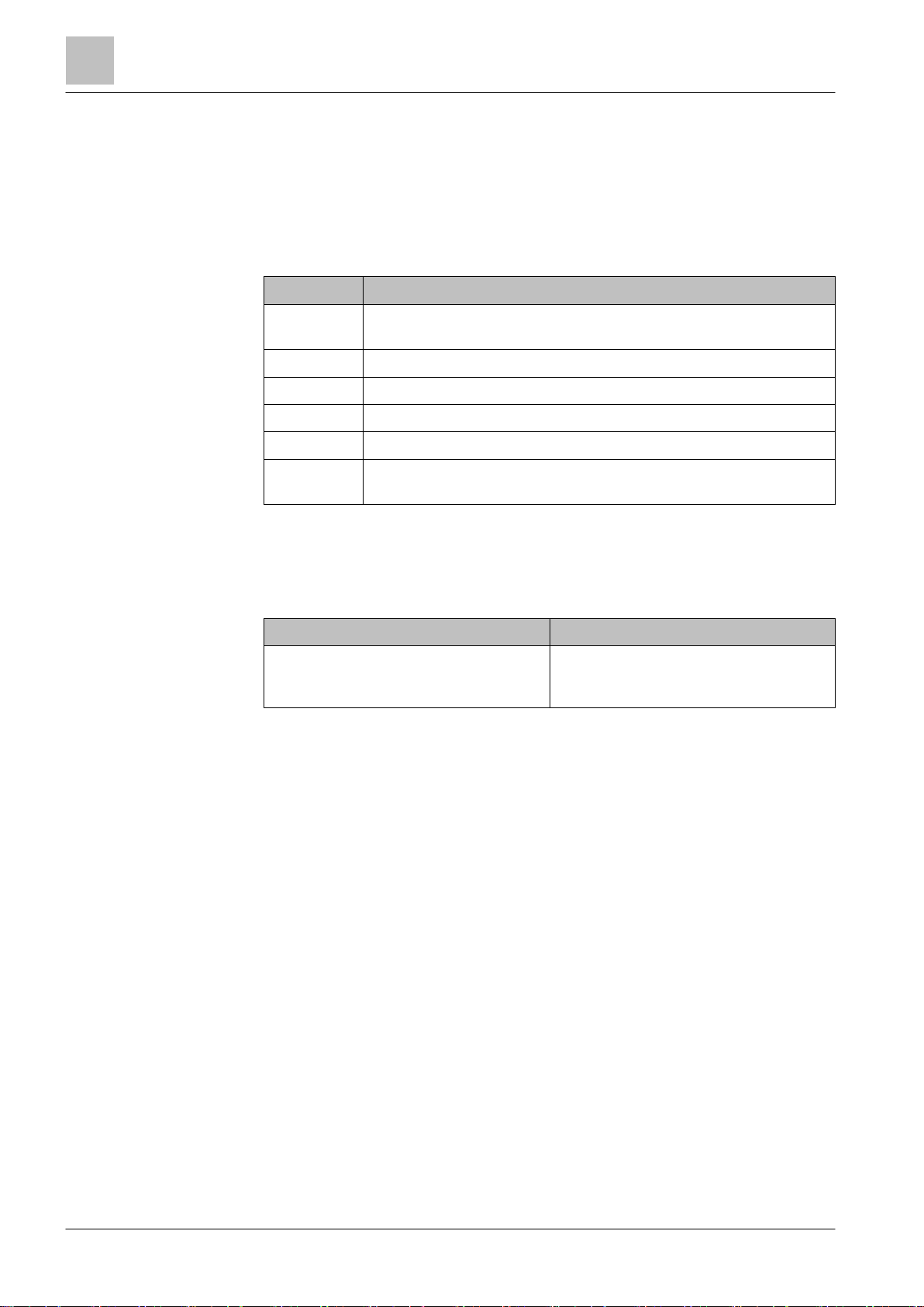
Target groups
The information in this document is intended for the following target groups:
Target group Activity Qualification
Installation personnel ● Assembles and installs the product
components at the place of
installation.
● Carries out a performance check
following installation.
Commissioning personnel ● Configure the product at the place of
installation according to customerspecific requirements.
● Check the product operability and
release the product for use by the
operator.
● Searches for and corrects
malfunctions.
Operating personnel ● Carries out procedures to correctly
operate the product.
Maintenance personnel ● Carries out all maintenance work.
● Checks that the products are in
perfect working order.
● Searches for and corrects
malfunctions.
● Has received specialist training in
the area of building installation
technology or electrical installations.
● Has obtained suitable specialist
training for the function and for the
products.
● Has attended the training courses
for commissioning personnel.
● No particular basic training is
needed.
● Has been instructed by the
commissioning personnel.
● Has obtained suitable specialist
training for the function and for the
products.
Building Technologies
7 | 124
Page 8
About this document
Applicable documents
1
Building Technologies
A6V10421795_en
--_gFire safety
2016-11-18
Document identification
The document ID is structured as follows:
A6Vxxxxxxxx_aaAA_vv
A6Vxxxxxxxx_--AA_vv
A6Vxxxxxxxx_aa--_vv
A6Vxxxxxxxx_----_vv
ID coding
1
Description
A6VxxxxxxxxSTEP-ID generated by the STEP system
_ Separator
aa Language abbreviation in accordance with ISO 639-1
AA Country abbreviation in accordance with ISO-3166-1
-- Multilingual or international
vv Document version, single or double digit: a, b, …z; aa, ab, …az;
ba, bb, …bz; etc.
1
Some documents have different ID that are generated by an earlier system.
There are also documents with up-to date ID codes along with additional
features in the designation.
ID code Examples
ID_languageCOUNTRY_version
-- = multilingual or international
A6V10215123_deDE_a
A6V10215123_en--_a
A6V10315123_----_a
Date format
The date format in the document corresponds to the recommendation of
international standard ISO 8601 (format YYYY-MM-DD).
Reference document and source language
● The source language of this document is English (en).
● The reference version of this document is the international version in English.
The international version is not localized.
The reference document has the following designation:
ID_en--_x
x = version, en = English, -- = international
8 | 124
Page 9

About this document
Applicable documents
A6V10421795_en
--_gFire safety
2016-11-18
Conventions for text marking
The 'i' symbol
identifies supplementary information and tips for an easier way of
Markups
Special markups are shown in this document as follows:
⊳ Requirement for a behavior instruction
1
1.
2.
– Version, option, or detailed information for a behavior instruction
⇨ Intermediate result of a behavior instruction
⇨ End result of a behavior instruction
● Numbered lists and behavior instructions with an operation
[➙ X] Reference to a page number
'Text' Quotation, reproduced identically
<Key> Identification of keys
> In addition to mathematical operator, for identification between
Supplementary information and tips
working.
Behavior instruction with at least two operation sequences
sequence
steps in a sequence, e.g., 'Menu bar' > 'Help' > 'Help topics'
1.1 Applicable documents
The list below is used as a reference for the FC361-xx fire control panel and as a
supplement to this document.
Number Name
008250 Operation manual FDUL221 line tester
A6V10210416 FS720 Fire Detection System, Commissioning,
Maintenance, Troubleshooting
A6V10419665 Datasheet FC361-xx fire control panel
A6V10421792 Installation FC361-xx fire control panel
A6V10421797 Operation manual FC361-xx fire control panel (short)
A6V10431009 Installation FTO3601-H1 evacuation module (NL)
A6V10431011 Installation FTO3602-Z1 LED indicator (16 zones)
A6V10431013 Installation FCA3601-Z1 / FCA3603-Z1 key switch
A6V10431015 Installation FCA3602-Z1 output card (4M)
A6V10450591 Installation FHD3601-Z1 door incl. PMI
A6V10450593 Installation FCM3601-Z1 mainboard
Building Technologies
9 | 124
Page 10

About this document
Download center
1
Building Technologies
A6V10421795_en
--_gFire safety
2016-11-18
You will also find information about search variants and links to mobile
Number Name
A6V10450595 Operation manual ‘FC360 Panel Configurator‘
A6V10882301 List of compatibility for FC361-xx fire control panel
A6V10893024 Installation FHA3602-Z1 semi flush mount bezel
1.2 Download center
You can download various types of documents, such as data sheets, installation
instructions, and license texts via the following Internet address:
http://siemens.com/bt/download
l Enter the document ID in the 'Find by keyword' input box.
applications (apps) for various systems on the home page.
1.3 Abbreviations
Abbreviations Explication
AVC Alarm Verification Concept
EOL End of Line
MCP Manual Call Point
PSU Power Supply Unit
PMI Person Machine Interface
EVAC Evacuation
GUI Graphical User Interface
EMC Electro Magnetic Compatibility
10 | 124
Page 11

About this document
History of changes
A6V10421795_en
--_gFire safety
2016-11-18
1.4 History of changes
The first edition of a language version or a country variant may, for example, be
The reference document's version applies to all languages into which the reference
document is translated.
version 'd' instead of 'a' if the reference document is already this version.
The table below shows this document’s history of changes:
Version Edition date Brief description
g 2016-11-18 Add information of mainboard FCM3601-Z1 and
1
door incl. PMI FHD3601-Z1 in chapter 5.12 and
chapter 12.
Change default setting of relay 3 in chapter 5.9
and 5.5.
Add ‘Intended use’ sub-chapter in chapter 2.1.
Some minor editorial changes.
f 2016-08-23 Add technical information on output card (4M)
concerning creeping open / creeping short when
the output is configured as RT fault in chapter
5.11.4.
e 2016-08-18 Add technical information on output card (4M)
concerning creeping open / creeping short in
chapter 3.4.2 and 5.11.4.
d 2016-07-22 Completely update the document.
c 2016-04-08 Add RS485 / RS232 communication parameters
in chapter 5.11.5.
Change name of ‘FC360 Tool’ to ‘FC360 Panel
Configurator’.
Change name of ‘FC360 Editor’ to ‘FC360
Desktop Editor’.
Change password of access level 3.1 in chapter
6.1.
Add information of updating firmware of FT2010
/ FT2011 / FDUL221 in chapter 9.7.
b 2016-02-23 Add sticker information in chapter 5.2.
Add description to quit replace mode in chapter
8.3.4.3.
Add how to adjust brightness in chapter 11.2.
Update information in chapter 3.4.2 and chapter
5.8 about the total output current of configurable
IOs and Aux power output is max. 0.2 A.
Add access level 3.1 in chapter 6.1.
Add action of P2 line overload in chapter 11.2.
Add ‘Shielded cable is required.’ for RS485
application in chapter 5.11.5.
a 2015-06-08 First version
Building Technologies
11 | 124
Page 12

About this document
History of changes
1
Building Technologies
A6V10421795_en
--_gFire safety
2016-11-18
The table below shows the published language versions and country variants with
the corresponding modification index:
Modification index en_-- de_-- fr_-- it_-- es_--
g X - X X X
f X - - X -
e X - - - -
d X - - X -
c X - - - -
b X - - - -
a X - - - -
X = published
- = no publication with this modification index
12 | 124
Page 13

Safety
Intended use
A6V10421795_en
--_gFire safety
2016-11-18
2 Safety
2.1 Intended use
The panel is intended to be mounted in a building to detect, evaluate and alarm in
the event of fire, together with C-NET detector line.
2.2 Safety instructions
The safety notices must be observed in order to protect people and property.
The safety notices in this document contain the following elements:
● Symbol for danger
● Signal word
● Nature and origin of the danger
● Consequences if the danger occurs
● Measures or prohibitions for danger avoidance
Symbol for danger
2
This is the symbol for danger. It warns of risks of injury.
Follow all measures identified by this symbol to avoid injury or death.
Additional danger symbols
These symbols indicate general dangers, the type of danger or possible
consequences, measures and prohibitions, examples of which are shown in the
following table:
General danger Explosive atmosphere
Voltage/electric shock Laser light
Battery Heat
Signal word
The signal word classifies the danger as defined in the following table:
Signal word Danger level
DANGER DANGER identifies a dangerous situation, which will result
directly in death or serious injury if you do not avoid this
situation.
Building Technologies
WARNING WARNING identifies a dangerous situation, which may
result in death or serious injury if you do not avoid this
situation.
CAUTION CAUTION identifies a dangerous situation, which could
result in slight to moderately serious injury if you do not
avoid this situation.
NOTICE NOTICE
result from non-observance.
identifies possible damage to property that may
13 | 124
Page 14
Safety
Safety regulations for the method of operation
2
Building Technologies
A6V10421795_en
--_gFire safety
2016-11-18
Nature and
origin of the danger
●
Measures / prohibitions for danger avoidance
Nature and origin of the
danger
●
Measures / prohibitions for danger avoidance
Electrical voltage
regulations.
How risk of injury is presented
Information about the risk of injury is shown as follows:
WARNING
Consequences if the danger occurs
How possible damage to property is presented
Information about possible damage to property is shown as follows:
NOTICE
Consequences if the danger occurs
2.3 Safety regulations for the method of operation
National standards, regulations and legislation
Siemens products are developed and produced in compliance with the relevant
European and international safety standards. Should additional national or local
safety standards or legislation concerning the planning, assembly, installation,
operation or disposal of the product apply at the place of operation, then these
must also be taken into account together with the safety regulations in the product
documentation.
Electrical installations
WARNING
Electric shock
● Work on electrical installations may only be carried out by qualified
electricians or by instructed persons working under the guidance and
supervision of a qualified electrician, in accordance with the electrotechnical
● Wherever possible disconnect products from the power supply when carrying
out commissioning, maintenance or repair work on them.
● Lock volt-free areas to prevent them being switched back on again by mistake.
● Label the connection terminals with external voltage using a
'DANGER External voltage' sign.
● Route mains connections to products separately and fuse them with their own,
clearly marked fuse.
● Fit an easily accessible disconnecting device in accordance with IEC 60950-1
outside the installation.
● Produce earthing as stated in local safety regulations.
14 | 124
Page 15

Safety
Safety regulations for the method of operation
2
A6V10421795_en
--_gFire safety
2016-11-18
Noncompliance with the following safety regulations
●
Compliance with the following regulations is required.
CAUTION
Risk of injury to persons and damage to property
● Specialist electrical engineering knowledge is required for installation.
● Only an expert is permitted to carry out installation work.
Incorrect installation can take safety devices out of operation unbeknown to a
layperson.
Mounting, installation, commissioning and maintenance
● If you require tools such as a ladder, these must be safe and must be intended
for the work in hand.
● When starting the fire control panel ensure that unstable conditions cannot
arise.
● Ensure that all points listed in the 'Testing the product operability' section below
are observed.
● You may only set controls to normal function when the product operability has
been completely tested and the system has been handed over to the customer.
Testing the product operability
● Prevent the remote transmission from triggering erroneously.
● If testing building installations or activating devices from third-party companies,
you must collaborate with the people appointed.
● The activation of fire control installations for test purposes must not cause
injury to anyone or damage to the building installations. The following
instructions must be observed:
– Use the correct potential for activation; this is generally the potential of the
building installation.
– Only check controls up to the interface (relay with blocking option).
– Make sure that only the controls to be tested are activated.
● Inform people before testing the alarm devices and allow for possible panic
responses.
● Inform people about any noise or mist which may be produced.
● Before testing the remote transmission, inform the corresponding alarm and
fault signal receiving stations.
Modifications to the system design and the products
Modifications to the system and to individual products may lead to faults,
malfunctioning and safety risks. Written confirmation must be obtained from
Siemens and the corresponding safety bodies for modifications or additions.
Modules and spare parts
● Components and spare parts must comply with the technical specifications
defined by Siemens. Only use products specified or recommended by
Siemens.
● Only use fuses with the specified fuse characteristics.
Building Technologies
15 | 124
Page 16

Safety
Release notes
2
Building Technologies
A6V10421795_en
--_gFire safety
2016-11-18
Limited or non
-
existent fire detection
detection installation.
Incorrect planning and/or configuration
detection installation.
● Wrong battery types and improper battery changing lead to a risk of explosion.
Only use the same battery type or an equivalent battery type recommended by
Siemens.
● Batteries must be disposed of in an environmentally friendly manner. Observe
national guidelines and regulations.
Disregard of the safety regulations
Before they are delivered, Siemens products are tested to ensure they function
correctly when used properly. Siemens disclaims all liability for damage or injuries
caused by the incorrect application of the instructions or the disregard of danger
warnings contained in the documentation. This applies in particular to the following
damage:
● Personal injuries or damage to property caused by improper use and incorrect
application
● Personal injuries or damage to property caused by disregarding safety
instructions in the documentation or on the product
● Personal injury or damage to property caused by poor maintenance or lack of
maintenance
2.4 Release notes
Limitations to the configuration or use of devices in a fire detection installation with
a particular firmware version are possible.
WARNING
Personal injury and damage to property in the event of a fire.
● Read the 'Release Notes' before you plan and/or configure a fire detection
installation.
● Read the 'Release Notes' before you carry out a firmware update to a fire
NOTICE
Important standards and specifications are not satisfied.
Fire detection installation is not accepted for commissioning.
Additional expense resulting from necessary new planning and/or configuration.
● Read the 'Release Notes' before you plan and/or configure a fire detection
installation.
● Read the 'Release Notes' before you carry out a firmware update to a fire
16 | 124
Page 17

Sa
fety
Cyber security disclaimer
A6V10421795_en
--_gFire safety
2016-11-18
2.5 Cyber security disclaimer
Products, solutions and services from Siemens include security functions to ensure
the secure operation of building automation and control, fire safety, security
management, and physical security systems. The security functions on these
products, solutions and services are important components of a comprehensive
security concept. Drafting, implementing and managing a comprehensive and upto-date security concept, customized to individual needs, is nevertheless
necessary, and may result in additional plant- or site-specific preventive measures
to ensure secure operation of your site regarding building automation and control,
fire safety, security management, and physical security. These measures may
include, for example, separating networks, physically protecting system
components, user training, multi-level defensive measures, etc. For additional
information on security as part of building technology and our product, solution and
service offerings, please contact your Siemens sales representative or project
department. We strongly recommend to always comply with our security advisories
on the latest security threats, patches and other related measures.
http://www.siemens.com/cert/en/cert-security-advisories.htm
2
Building Technologies
17 | 124
Page 18

System description
System overview
3
Building Technologies
A6V10421795_en
--_gFire safety
2016-11-18
C-NET
2
3 System description
3.1 System overview
The panel is a compact panel with an integrated operating unit for processing
signals from FD720 devices. See list of compatibility A6V10882301 in chapter
'Applicable documents [➙ 9]'.
The panel is operated as standalone control panel.
The panel supports operation of the C-NET detector line in a loop or stub.
Automatic fire detectors (e.g. smoke and heat detectors), manual call points, I/O
modules and other C-NET devices are connected to the C-NET detector line.
The picture below shows the FC360 system overview.
3
1
4
Figure 1: Overview of FC360 system
1 Fire control panel FC361-xx
2 C-NET detector line
3 Sounders, RT fire, RT fault, Fire controls, configurable IOs
4 FC360 configuration tools (i.e.,'FC360 Panel Configurator', 'FC360 Desktop
Editor') for configuration via PC
18 | 124
Page 19

System description
Features
A6V10421795_en
--_gFire safety
2016-11-18
3.2 Features
System
● Monitors detector and sounder lines
● Up to 126 addresses per loop
● LCD with 7 lines, max. 21 characters per line
● Up to 2000 events can be stored in history log with date and time stamp
● Alarm counter for up to 999 alarms
● Integrated configuration tool 'FC360 Panel Configurator'
● Automatic summer / winter time change
● Country specific settings
● Multilingual
3
Building Technologies
19 | 124
Page 20

System description
Panel types
3
Building Technologies
A6V10421795_en
--_gFire safety
2016-11-18
3.3 Panel types
Overview of panels and options
FC361-ZZ FC361-ZA
batteries max. 2x 12 Ah
without LED indicator
FC361-YZ FC361-YA
batteries max. 2x 12 Ah
with LED indicator (16 zones)
batteries max. 2x 25 Ah
without LED indicator
batteries max. 2x 25 Ah
with LED indicator (16 zones)
20 | 124
More options
● Output card (4M)
● Evacuation module (NL)
● LED indicator (16 zones)
● Key switch
● Key switch (Nordic)
● RS232 module
● Ext. printer DL3750+
● Output module FCA1209-Z1
● Semi flush mounting bezel
Page 21
System description
Technical data
A6V10421795_en
--_gFire safety
2016-11-18
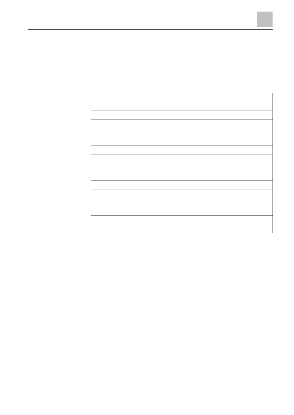
3.4 Technical data
Information on approvals, CE marking, and the relevant EU directives for this
device (these devices) is available in the following document(s); see chapter
'Applicable documents':
● Document A6V10419665
3.4.1 General data
Detector line
Number of detector lines 1 loop or 2 stubs
Number of addresses Max. 126
Inputs / outputs
Number of sounder circuits 2
Number of relay outputs 3
Number of configurable inputs / outputs 4
Options
3
RS232 module Max. 1
Ext. printer DL3750+ Max. 1
LED indicator (16 zones) Max. 1
Evacuation module (NL) Max. 1
Key switch / Key switch (Nordic) Max. 1
Output card (4M) Max. 1
Alarm counter Max. 999 alarms
Event memory Max. 2000 events
Building Technologies
21 | 124
Page 22
System description
Technical data
3
Building Technologies
A6V10421795_en
--_gFire safety
2016-11-18
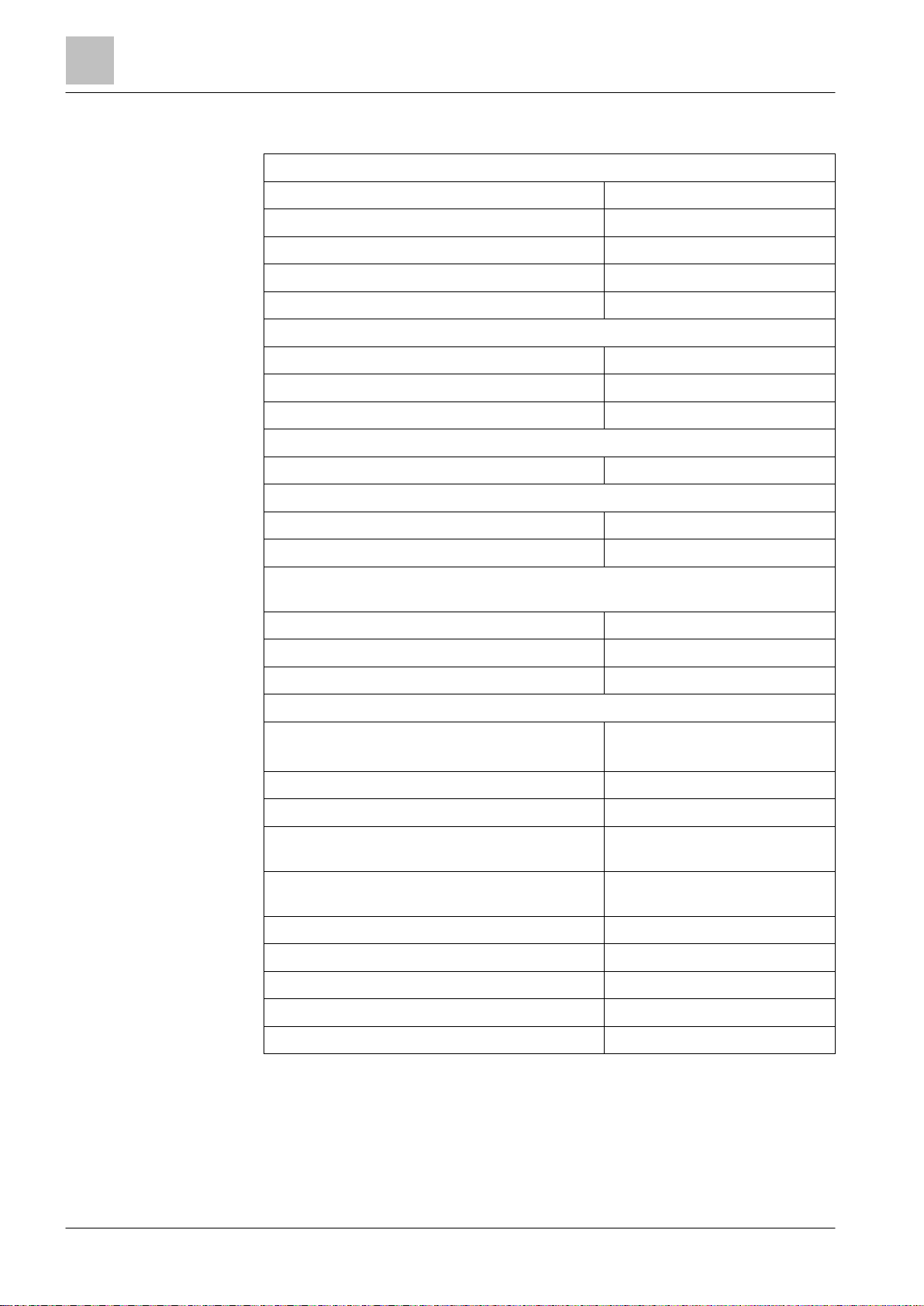
3.4.2 Electrical data
Rating detector line
Operating voltage DC 12…33 V
Operating current Max. 0.5 A
Line resistance / capacitance Max. 240 Ω / Max. 500 nF
Monitored for earth fault Yes
Monitored for open / short circuit Yes
Sounders on mainboard
Voltage / current DC 24 V / 0.5 A
EOL element Resistor 2.2 kΩ / 1 W / 0.5 %
AUX. power output (max.) DC 24 V / 0.2 A
Configurable IOs on mainboard
Voltage / current DC 24 V / 0.1 A
Outputs on output card (4M) FCA3602-Z1
Voltage / current DC 26 V / 1.0 A
1
2
3
EOL element Resistor 2.2 kΩ / 1 W / 0.5 %
Additionally for outputs on output card (4M) FCA3602-Z1 with the functionality
‘creeping open / creeping short’
Line resistance Max. 74.3 Ω
Sounder voltage Min. DC 16 V
Relay outputs on mainboard DC 60 V / 2.0 A
Power supply
Mains voltage AC 97…127 V
AC 196…253 V
Mains fuse AC 250 V / 2.5 AT
Power consumption 70 W
Max. nominal output current with battery
charging, I
max a
Max. nominal output current without battery
charging, I
max b
0.9 A
2.5 A
Min. output current 0.05 A
System supply voltage DC 20.5…28.6 V
Mains failure delay 1 min., 5 min., 10 min., 29 min.
22 | 124
Battery low discharge cut off DC 20.5…21 V
Temperature compensation Yes
Page 23
System description
Technical data
A6V10421795_en
--_gFire safety
2016-11-18
Batteries
Operating time Up to 72 h
Battery capacity 2x 12 V, 7 Ah / 12 Ah / 25 Ah,
sealed lead acid
Voltage DC 20.5…28.6 V
Charging current Max. 1.6 A
3
Load resistance R
1
Each sounder has an output current of max. 0.5 A. The total output current of
imax
both sounder lines is max. 0.5 A.
2
Each configurable IO on the mainboard has an output current of max. 0.1 A.
The total output current of configurable IOs and aux. power output is
max. 0.2 A.
3
Each output on the output card (4M) has an output current of max. 1.0 A. The
total output current of output card (4M) is max. 2.0 A.
3.4.3 Mechanical data
Terminals 0.2…2.5 mm
Dimensions (W x H x D) 402 x 372 x 132 mm 402 x 372 x 211 mm
Weight (without batteries) 5.24 kg 6.44 kg
Color
- Housing, Cover RAL Design 000 50 00
Max. 1 Ω
FC361-ZZ / FC361-YZ FC361-ZA / FC361-YA
2
Building Technologies
3.4.4 Environmental conditions
Operating temperature -5…+40 °C
Storage temperature -20…+60 °C
Air humidity (no condensation permitted) ≤95 % rel.
Protection category (IEC 60529) IP30
23 | 124
Page 24

S
ystem description
Structure
3
Building Technologies
A6V10421795_en
--_gFire safety
2016-11-18
322
1
4
5
8
3.5 Structure
The figure below shows the structure of the panel with open front cover.
7
6
Figure 2: Structure of FC360 panel
1 Power supply
2 Batteries
3 Mainboard
4 Optional output card (4M)
5 RS232 module
6 PMI board
7 Space for options (e.g. Evacuation module (NL), LED indicator (16 zones),
key switch)
8 Mains fuse holder
24 | 124
Page 25

Options with requirements
A6V10421795_en
--_gFire safety
2016-11-18
4 Options with requirements
RT device confirmation signal;
The following options with requirements as defined in EN 54-2/A1 are available.
The table below explains how to realize these options in the panel.
The relevant sections according to EN 54-2/A1 are specified in the left column of
the table.
4
EN 54-2
Options with requirements
7.8 Output C to fire alarm devices
according to EN 54-1
Function in FC361-xx
Installation Configuration 1 / Operation Chapter
Monitored output
Sounder control 5
Sounder lines
C-NET devices
7.9.1 Output E to fire alarm routing
equipment
Monitored output
card (4M)
RT fire 5.11.4
according to EN 54-1
7.9.2 Alarm confirmation input from fire
alarm routing equipment
Input
LED fire brigade activated via
input
7.10.1 Outputs G to fire protection equipment
according to EN 54-1
Monitored output
card (4M)
Fire output 5.11.4
7.11 Delays to outputs - Alarm Verification Concept;
'Manned' / 'Unmanned'
7.12.1 Dependencies on more than one
alarm signal, type A dependency
- Type A inhibit time
30…60 sec.
Reset of the first alarm after
90 sec.
7.13 Alarm counter - Alarm counter -
6
7
5.8
-
-
8.3 Fault signals from points - RT fault 5.11.4
8.8 Output to fault warning routing
Relay 2 RT fault 5.5
equipment
8.9 Output J to fault warning routing
equipment
Monitored output
card (4M)
RT fault 5.11.4
according to EN 54-1
9.5 Disablement of addressable points - Disable -
10 Test condition - Test -
1
You will find more information about configuration in document A6V10450595.
Building Technologies
25 | 124
Page 26

Installation
Instruction
5
Building
Technologies
A6V10421795_en
--_gFire safety
2016-11-18
Voltage
system is de
-
energized.
Electrostatics
modules.
5 Installation
5.1 Instruction
WARNING
Electric shock
● Installation work may only be undertaken by qualified staff and when the
NOTICE
Damage to electronics
● Suitable protective measures must be taken when working with electronics
● Specialist electrical engineering knowledge is required for installation.
● Only an expert is permitted to carry out installation work.
Incorrect installation can take safety devices out of operation unbeknown to a
layperson.
The installation must comply with all applicable national and local regulations.
● The panel must be installed in a dry, clean and well vented room.
● The panel and its components must be protected against dampness and
interfering external influences such as dust, great temperature fluctuations and
mechanical stress.
● The panel must be installed in a place freely accessible to authorized staff and
the emergency services.
● The panel must be fitted to a level, non-vibrating wall surface with load bearing
capacity using suitable mounting materials (e.g. screws and plugs).
● The installation surface and selected wall must be suitable for the weight of the
panel including the batteries used.
● Installation is not permitted in rooms with high levels of electromagnetic
interference, e.g. in control rooms or right next to power cables and inductive
loads.
Mounting options
There are two options for mounting the panel:
● Surface mounting [➙ 28]
● Semi flush mounting, refer to document A6V10893024, see chapter 'Applicable
documents [➙ 9]'
26 | 124
Page 27

Installation
Instruction
5
A6V10421795_en
--_gFire safety
2016-11-18
Figure 3: Mounting the panel
1 Recommended display height approx. 1.6 to 1.7 m
2 Panel width: 402 mm
3 Distance from door of at least one door leaf in width
4 Panel height: 372 mm
27 | 124
Building Technologies
Page 28

Installation
Surface mounting
5
Building
Technologies
A6V10421795_en
--_gFire safety
2016-11-18
5.2 Surface mounting
Steps:
1. Define the mounting location.
2. Open the door of the panel using a screw driver.
3. Break out the required cable entries (A).
– Screw cable glands (B) for all open entries. The cable glands are not
included.
– The mains cable must be fed into housing on the right from above. Signal
and control cables can be fed into housing through the remaining entries.
4. Mark position of mounting holes (D) on the wall.
5. Drill the holes and insert rawl plugs (not included).
6. Attach and fasten the panel using screws (Ø ≥5 mm, not included).
7. Stick the supplied aluminum stickers over all holes for wall mounting.
8. Optional: Mounting accessories (C). See 'Accessories [➙ 44]'.
9. Switch off the mains supply AC 230 V and connect the mains cable. See
'Power supply - mains voltage [➙ 29]'.
10. Connect signal and control cable (detector lines, sounder lines, inputs/outputs
and relays). See 'C-NET detector line [➙ 32]', 'Sounder [➙ 38]', 'Inputs
/outputs [➙ 39]', 'Relay [➙ 41]'.
11. Switch on mains supply AC 230 V.
12. Connect batteries. See 'Battery [➙ 30]'.
a The panel is ready for commissioning. See 'Commissioning [➙ 96]'.
13. Test the functionality of the panel.
14. Close the door of the panel.
a Handover the system to the customer.
28 | 124
Figure 4: Details of mounting
A Cable entries
Cable glands
B
C Accessories
D Mounting holes
Page 29

Installation
Power supply
-
mains voltage
A6V10421795_en
--_gFire safety
2016-11-18
5.3 Power supply - mains voltage
Electrical voltage!
2
1
4
N
WARNING
Electric shock
Before connecting the mains voltage ensure that power is not switched on and is
locked to prevent it from being switched on.
1. Insert the mains cable (1) into the housing from the top right side. Use mains
cable with cross section of 3*1.5 mm2 up to 3*2.5 mm2.
2. Insulate the mains cable (1) as needed and connect to the mains fuse
holder (4).
3. Secure the cable with a cable tie.
3
5
5
Figure 5: Connection of power supply
1 Mains cable
2 Boundary of mains zone
3 Safety zone (no 230 V power permitted)
4 Mains fuse holder
5 Ground terminal
Building Technologies
29 | 124
Page 30
Installation
Battery
5
Building
Technologies
A6V10421795_en
--_gFire safety
2016-11-18
Error during configuration detection
complete.
Fully
discharged batteries may be unable to correctly recharge. Replace batteries
The fire control panel is approved with the batteries listed above, use only
Acc
u
A
ccu
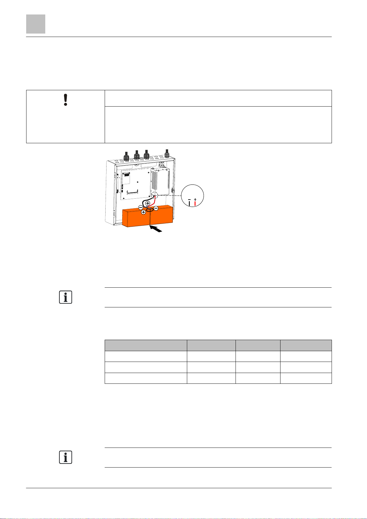
5.4 Battery
When the AC mains voltage fails, the emergency power supply will be provided by
the connected batteries with no interruption. The emergency power bridging time is
based on the control panels quiescent and alarm current as well as battery capacity.
NOTICE
Additional effort for troubleshooting
● Only connect the battery connection cables (1) once all installation work is
1
Figure 6: Connection of batteries
Emergency power bridging time
National and local regulations may require a bridging time of up to 72 hours for the
emergency power supply. Use the 'FX3610 Cerberus FIT Quantities tool' to
calculate the required battery capacity.
that have been fully discharged.
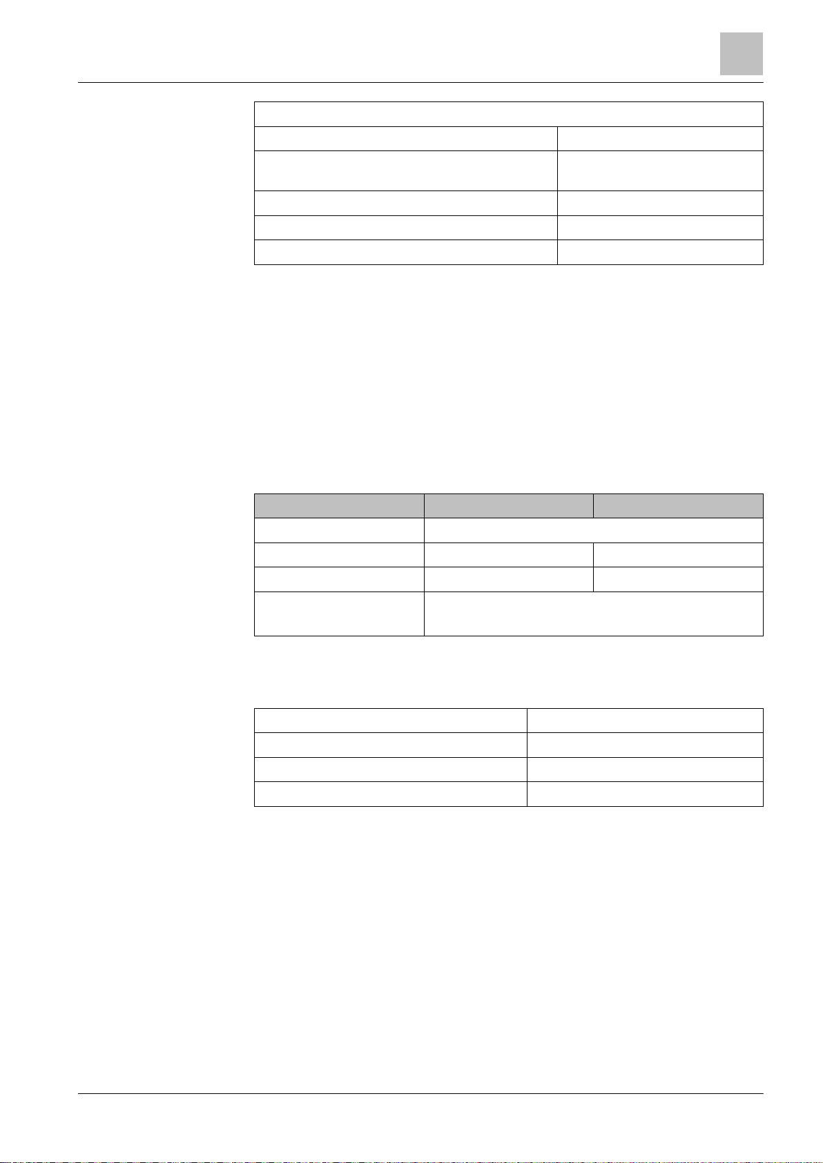
Determining battery type
Determine the battery type based on the calculated battery capacity (see table).
Designation Type Capacity Order number
Battery (12 V, 7 Ah, VdS) FA2003-A1 7 Ah A5Q00019353
Battery (12 V, 12 Ah, VdS) FA2004-A1 12 Ah A5Q00019354
Battery (12 V, 25 Ah, VdS) BAT12-25 25 Ah S54302-Z102-A1
Notes:
● Two batteries must be connected in series to achieve the system voltage of 24 V.
● Batteries are not supplied with the panels and must be ordered separately.
● Battery capacity determines charging current. The charging current must be
taken into account when calculating the power supply.
● Battery dimensions determines the housing type.
Siemens provided batteries.
30 | 124
Page 31

Installation
Connection overvie
w
A6V10421795_en
--_gFire safety
2016-11-18
5.5 Connection overview
The picture below shows the overview of the panel connection.
5
Figure 7: Connection overview of FC360 panel
EOL Resistor 2.2 kΩ
Relay Output module FCA1209-Z1
1 Connection of sounder lines
2 Aux. power supply DC 24 V / 0.2 A
3 Configurable IO, default setting as 'Input'
4 Configurable IO, default setting as 'Unmonitored output'
5 Output relay, default setting as 'RT fire'
6 Output relay, default setting as 'RT fault'
7 Output relay, default setting as 'Fire alarm'
8 Connection of detector lines (1 loop / 2 stubs)
Building Technologies
31 | 124
Page 32

Installation
C-NET detector line
5
Building
Technologies
A6V10421795_en
--_gFire safety
2016-11-18
5.6 C-NET detector line
Up to 126 devices, such as automatic fire detectors (e.g. smoke or heat detectors),
manual call points, I/O modules and other C-NET components, can be connected
to the C-NET detector line.
The connection for the C-NET detector line is on the main board. Most line
devices, such as fire detectors, are supplied directly by C-NET with the required
operating voltage. FDCI723 and special applications with I/O modules require an
external power supply.
The picture below shows the C-NET detector line connection with peripheral
devices.
Figure 8: Overview of FC360 C-NET detector line
Line separator
All C-NET devices have an integrated line separator.
In the event of a short-circuit in the C-NET wiring, the line separators adjacent to
the wiring fault are opened and the faulty cable segment is shut down. The C-NET
devices remain functional and ready to detect. The fault is displayed on the panel.
Connection factor
The max. number of connectable C-NET peripherals (126 devices) and the max.
line length (3300 m) depend on the device connection factor.
Details must be calculated using the 'FX3610 Cerberus FIT Quantities tool'
A6V10885143.
32 | 124
Page 33

Installation
C-NET detector line
5
A6V10421795_en
--_gFire safety
2016-11-18
5.6.1 Connectable C-NET devices
The table below contains a list of all devices which can be connected to the C-NET
detector line. It also highlights the devices with an alarm indicator (AI) and to the
devices an external alarm indicator (EAI) or a sounder base (DBS720) can be
connected.
X possible / available
– not possible / not available
Device type Type Description AI Ext. AI DBS720
Point detectors OP720 Smoke detector X X X
HI720 Heat detector (static+ROR) X X X
HI722 Heat detector (static) with temperature report
X X X
support
OH720 Multi-sensor smoke detector X X X
OOH740 Multi-sensor smoke detector;
X X X
DualProtocol Collective
Special detectors FDF241-9 Infrared flame detector (2 sensors / 1 photo
X X –
diode);
DualProtocol Collective
FDL241-9 Linear smoke detector; DualProtocol Collective X X –
OOHC740 Neural fire and CO detector with ambient
X X X
supervision
Manual call
points
FDM221
FDM231
Manual call point, direct action X – –
FDM223 Manual call point, indirect action X X –
FDM224 Manual call point, direct action X X –
FDM225 Manual call point, direct action X – –
FDM226 Manual call point, direct action X – –
Line modules FDCI221 Input module (1 input) X – –
FDCI222 Input module (4 inputs) X – –
Alarm devices FDS221 Alarm sounder X X –
Building Technologies
FDCI723 Zone module, ext. powered (1 collective line) X – –
FDCIO221 Input/Output module (1 input and 1 output) X – –
FDCIO222
Input/Output module (4 inputs and 4 outputs) X – –
FDCIO224
FDCL221 Line separator X – –
FDCL221-M Multi line separator module (8…9 isolators) X – –
FDS229 Alarm sounder with supplementary optical
X X –
indication
DBS720 Sounder base – – –
DBS721 Sounder interbase – – –
DBS728 Sounder beacon interbase (supports EN 54-23) – – –
33 | 124
Page 34

Installation
C-NET detector line
5
Building
Technologies
A6V10421795_en
--_gFire safety
2016-11-18
The complete
compatibility list is available in document A6V10882301. See
Influencing the
earth fault monitoring
isolated.
Device type Type Description AI Ext. AI DBS720
DBS729 Sounder beacon interbase – – –
Base DB721 Detector base with loop contact X X –
Operation and
indication
devices
FT2010 Floor repeater terminal (FRT) X – –
FT2011 Floor repeater display (FRD) X – –
FDCAI221 Addressable alarm indicator – – –
chapter 'Applicable documents [➙ 9]'.
NOTICE
● Devices on the C-NET with a separate supply, the supply must be electrically
See also
2 About this document [➙ 7]
34 | 124
Page 35

Installation
C-NET detector line
A6V10421795_en
--_gFire safety
2016-11-18
5.6.2 C-NET topology
C-NET
C-NET
Permissible topology for the C-NET
The C-NET can be wired in the topology shown below. Regardless of the topology
(loop, stub or loop with sub-stub), the C-NET system limits, such as length, cable
resistance etc., must be observed.
Either one loop or two stubs can be connected to the panel’s C-NET detector line.
Loop
(1 loop, max. 126 devices)
Stub
(2 stubs, max. 32 devices per stub)
5
Wiring NOT permissible
Sub-stubs on loop
A sub-stub must only be connected between two devices or line
separators as well as directly to the terminal connection.
NOT permissible
Sub-stub on sub-stub of loop
NOT permissible
Sub-stub on a stub
Building Technologies
35 | 124
Page 36

Installation
C-NET detector line
5
Building
Technologies
A6V10421795_en
--_gFire safety
2016-11-18
LOOP1
5.6.3 Wiring on C-NET devices
The connection terminals for the loop (detector line, C-NET) are on the main board.
The position is shown as below.
Figure 9: Position of C-NET detector line terminal
Each C-NET device has the terminals for directly connecting the C-NET wire.
Loop wiring
Connection terminal
Detector base and sounder base
● 1b (corresponds to +,
input/output)
● 5 (corresponds to input)
● 6 (corresponds to output)
Manual call point
Input/output modules
36 | 124
Zone module
Alarm sounder with supplementary
optical indication
Page 37

Installation
C-NET detector line
A6V10421795_en
--_gFire safety
2016-11-18
Stub wiring
Max.
32 devices may be connected to a single stub as per EN
54-2.
Figure 10: Stub connection of C-NET detector line
(A)
When using shielded connection cables: Cable shielding must be connected
to the panel’s earth terminal.
5
Building Technologies
37 | 124
Page 38

Installation
Sounder
5
Building
Technologies
A6V10421795_en
--_gFire safety
2016-11-18
Sounder
–+2
211
EOL
5.7 Sounder
The panel mainboard has two sounder lines. They are monitored from the terminal
to the EOL for open and short circuits.
Application:
Sounder control
Technical:
● Current of each sounder line: max. 0.5 A @ DC 24 V
● Total available current of both sounder lines: max. 0.5 A @ DC 24 V
● Each line must be terminated with an EOL element (Resistor 2.2 kΩ)
EOL
–
+
Figure 11: Connection of sounder line
38 | 124
Page 39

In
stallation
Inputs / outputs
A6V10421795_en
--_gFire safety
2016-11-18
5.8 Inputs / outputs
The panel mainboard has four configurable inputs / outputs. Each one can be
configured as an input or output.
The default settings are:
● IO1 / IO2: input
● IO3 / IO4: output
5
Figure 12: Connection of configurable IOs
1 Configured as input (Connect to '0V' and IO)
2 Configured as output (Connect to '24V' and IO)
Configured as 'input'
The inputs can be triggered by a potential-free contact. They can be configured as
one of the control functions below:
Mode Functionality
class change Activates all sounder lines and addressable sounders as
long as the input is closed ('Continuous' tone on sounder
lines and 'Tone 1' on addressable sounders).
Evacuation usage Activates all the sounder lines and addressable sounders
as long as the input is closed.
The silence / resound functions are available for the
sounder lines and addressable sounders in this state.
Reset command Resets the acknowledged alarm events if the input is
closed (only after acknowledge command).
Access level 2 Enables access level 2 as long as the input is closed.
Building Technologies
Disable RT Fire and
RT Fault devices
Disables all the RT fire and RT fault devices as long as
the input is closed.
Disabled RT outputs cannot be enabled by the menu
operation.
Activate manned Switches to 'Manned' mode as long as the input is closed.
Toggle between
manned/ unmanned
Toggles between 'Manned' / 'Unmanned' if the signal
changes on the input.
39 | 124
Page 40

Installation
Inputs / outputs
5
Building
Technologies
A6V10421795_en
--_gFire safety
2016-11-18
The IO1 is configured as output by default if the country selection is '
NL: With
Mode Functionality
Initiate extra PSU
fault
Dialer (RT Fire
Device) Fault
Activates external PSU fault as long as the input is
closed.
Activates RT fire device fault as long as the input is
closed.
The ‘RT Fire Fault’ LED and the ‘General Fault’ LED are
ON.
Initiate fire brigade is
called
Acknowledge
Generates an ‘Fire brigade is called’ event as long as the
input is closed. The ‘Fire brigade’ LED is ON.
Acknowledge all events as long as the input is closed.
command
Configured as 'output'
Configuration as 'output' allows the activation of external devices (e.g. relays) with
24 V voltage.
The line is not monitored.
Technical:
● Max. current of each output: 0.1 A
● Total max. current of four outputs (if configured) including AUX power output:
0.2 A.
FTO3601 H1 (EVAC field)'.
40 | 124
Page 41

Installation
Relay
A6V10421795_en
--_gFire safety
2016-11-18
5.9 Relay
The output “RT fault” is closed (inverse function) in
quiescent mode.
The panel mainboard has three relay outputs used for controlling without line
monitoring.
They can be freely configured as:
● RT fire
● RT fault
● Fire control
● Fire alarm
The default settings are:
● Relay 1: RT fire
● Relay 2: RT fault
● Relay 3: Fire alarm
Technical:
Current of each relay: max. 2 A @ DC 60 V
5
Building Technologies
Figure 13: Connection of relays
In case of fault, the contacts open.
41 | 124
Page 42

Installation
Terminals and switches
5
Building
Technologies
A6V10421795_en
--_gFire safety
2016-11-18
5.10 Terminals and switches
The picture below shows the position of terminals and switches.
42 | 124
Figure 14: Position of terminals and switches
Terminals Description
X3 Sounder lines
X5 Supply output (24 V)
X6…X9 Configurable inputs / outputs
X11…X13 Relay outputs
X15 Loop1 (C-NET detector line)
X29 Connection to PMI board
X39 Connection to output card (4M)
X26 Connection to PC
X22 Connection to power supply
Page 43

Installation
Terminals and switches
A6V10421795_en
--_gFire safety
2016-11-18
X22 Pin assignment
Pin Description
1 Message input from the power supply: Battery fault
2 Message input from the power supply: Mains fault
3 Supply input from the power supply (+)
4 Supply input from the power supply (+)
5 Supply input from the power supply (-)
6 Supply input from the power supply (-)
S1: Reset key for panel
Operation Function
Press one time Panel shuts down and restarts.
S2: Reset key for detection module (for factory use only)
5
Operation Function
Press one time The C-NET detector line is powered off and the panel
reports a fatal fault of detection module. You can power
on the C-NET detector line and remove the fatal fault by
'Reset detection module' menu. Refer to chapter 'Reset
detection module [➙ 92]'.
NOTICE! Do not use! For factory use only! Otherwise a
fatal error will occur!
S3: Switch for buzzer
Position Function
On Buzzer is on for an event (default).
Off Buzzer is off for an event.
S4: Switch for earth fault detection
Position Function
On Earth fault monitoring activated (default).
Off Earth fault monitoring deactivated.
Building Technologies
43 | 124
Page 44

Installation
Accessories
5
Building
Technologies
A6V10421795_en
--_gFire safety
2016-11-18
5.11 Accessories
5.11.1 Key switch (FCA3601-Z1) /
Key switch (Nordic) (FCA3603-Z1)
FCA3603-Z1
FCA3601-Z1
Figure 15: Installation of key switch
Function:
The key switches directly enable access level 2 operations.
Installation:
Detailed information on installation is available in document A6V10431013. See
chapter 'Applicable documents [➙ 9]'.
Configuration:
No configuration is required.
44 | 124
Page 45

Installation
Accessories
A6V10421795_en
--_gFire safety
2016-11-18
5.11.2 Evacuation module (NL) (FTO3601-H1)
3
4
FTO3601-H1
Figure 16: Installation of evacuation module (NL)
Function:
The evacuation module (NL) provides the Dutch special function. It activates the
EVAC zone by pressing the <START> button twice and deactivates the EVAC
zone by pressing the <STOP> button twice.
5
Installation:
Detailed information on installation is available in document A6V10431009. See
chapter 'Applicable documents [➙ 9]'.
Configuration:
The evacuation module (NL) is configured by default when starting up with country
setting 'NL: With FTO3601 H1 (EVAC field)'.
Operation:
1
2
Figure 17: PMI of evacuation module (NL)
No. Description Status Function
1 LED: EVAC zone active On EVAC zone 1 is activated.
2 LED: EVAC fault Flashing One or more sounders are in fault.
2x Start
2x Stop
Storing
Ontruimingsalarm
On All sounder devices are disabled.
3 Button: 'START' - Press twice quickly to start all
sounder devices.
4 Button: 'STOP' - Press twice quickly to stop all
sounder devices.
The LED and button 'Silence/Resound' on panel PMI are deactivated if the
evacuation module (NL) is installed and configured.
45 | 124
Building Technologies
Page 46

Installation
Accessories
5
Building
Technologies
A6V10421795_en
--_gFire safety
2016-11-18
5.11.3 LED indicator (16 zones) (FTO3602-Z1)
FTO3602-Z1
Figure 18: Installation of LED indicator (16 zones)
Function:
The LED indicator (16 zones) shows the actual alarm status of each section
(max. 16 sections of a panel).
● Flashing LED indicates first section in alarm.
● Static LED on indicates further sections in alarm.
Installation:
Detailed information on installation is available in document A6V10431011. See
chapter 'Applicable documents [➙ 9]'.
Configuration:
No configuration is required.
46 | 124
Page 47

Installation
Accessories
A6V10421795_en
--_gFire safety
2016-11-18
5.11.4 Output card (4M) (FCA3602-Z1)
FCA3602-Z1
Figure 19: Installation of output card (4M)
5
Figure 20: Connection overview of output card (4M)
Figure 21: Connection of internal power
Function:
The output card (4M) has four monitored outputs: OUT1…OUT4.
The default settings for the outputs are:
● OUT1: RT fire
● OUT2: RT fault
● OUT3 / OUT4: Sounder line
DC 24 V @ 2 A power supply is required. There are two options for power
connection:
● Internal connection, see Fig. 'Connection of internal power'.
● External connection, power is provided via external power supply (FP120-Z1).
Connection terminals on the output card (4M), see Fig. 'Connection overview of
output card (4M)'.
In addition to the default monitoring (short and open) the outputs can be configured
to monitor the output lines for creeping open and creeping short circuits.
47 | 124
Building Technologies
Page 48

Installation
Accessories
5
Building
Technologies
A6V10421795_en
--_gFire safety
2016-11-18
Electrical voltage
●
Disconnect power cable at the terminal '20
-
30V' on the output card (4M)
Installation:
WARNING
Before installation with output card (4M):
● Switch off the panel’s power supply.
Detailed information on installation is available in document A6V10431015. See
chapter 'Applicable documents [➙ 9]'.
Technical:
● Max. current of each output: 1.0 A @ DC 26 V
● Max. current of total outputs: 2.0 A @ DC 26 V
● Each line must be terminated with EOL element (Resistor 2.2 kΩ / 1 W /
0.5 %).
● Additional technical details if option creeping open / creeping short is activated:
– When the output is configured as RT fire, sounder line, fire control, max.
line resistance is 74.3 Ω; min. sounder voltage is DC 16 V.
– When the output is configured as RT fault, the resistance scope is
350 Ω ~ 2500 Ω.
Configuration:
Refer to chapters 'Add output card (4M) [➙ 105]' and 'Calibrate output card (4M)
[➙ 93]'.
Checking the line resistance depending on the required current
It must be calculated to ensure the supply of the connected devices is met.
The picture shows the dependence of the line resistance (R Line) in relation to the
device voltage (U
current of the connected devices (I Load).
Figure 22: Connection of the line resistance and EOL
Procedure for determining the maximum available device current (I Load):
1. Determine the line resistance R Line:
), the available output current (I
min
) and the minimum required
max
2. Detecting the voltage U
3. Verification: Are all parameters satisfied for the correct operations?
48 | 124
– Configuring: Refer to chapter 'Calibrate output card (4M) [➙ 93]'
– 'Engineering' > 'Calibrate 4M card line' > 'Output' 1-n > 'Calibrate EOL'
as per the device datasheet.
min
Page 49

Installation
Accessories
A6V10421795_en
--_gFire safety
2016-11-18
The table below can be used for this check, they display the maximum values.
Details must be calculated individually.
Imax R Line [Ω] @ Umin = 16 V
0.1 A 0…74.3
0.2 A 0…34.1
0.4 A 0…14
0.6 A 0…7.2
0.8 A 0…3.9
1 A 0…1.9
Counteractive measures: Reduction of I Load or R Line
5
49 | 124
Building Technologies
Page 50

Installation
Accessories
5
Building
Technologies
A6V10421795_en
--_gFire safety
2016-11-18
5.11.5 RS232 module
The RS232 module (FCA2001-A1) is used to connect an event printer.
Installation:
Figure 23: Installation of RS232
1 RS232 module
2 X10, slot for connection of the modules
1. Insert the module into the slot X10.
2. Secure the module to the mainboard using the two screws.
3. Wire up the module according to the pin assignment.
PIN assignment:
RS232
PIN Designation Description
8 ← DCD Data carrier detected
7 ← DSR Data set ready
6 ← CTS Clear to send
5 0 V Ground
4 ← RXD Received data
3 DTR → Data terminal ready
2 TXD → Transmitted data
1 RTS → Ready to send
Configuration:
No configuration is required.
50 | 124
Communication parameter settings:
● Baudrate: 9600
● Parity: None
● Data bits: 8
● Stop bits: 1
● Flow control: None
Page 51

Installation
Accessories
A6V10421795_en
--_gFire safety
2016-11-18
5.11.6 Event printer (Optional)
FUJITSU DL3750+
FC361-xx
TXD
RXD
GND
B
A
The RS232 module connects one external printer Fujitsu DL3750+ to the panel.
Detailed information on the printer is available on the CD supplied with the printer.
Connection:
Precondition: RS232 module is installed. See chapter 'RS232 module [➙ 50]'.
The picture below shows the connection between printer and panel.
FCA2001-A1
5
The connection cable is wired as per the following connection diagram.
● The connection cable has a maximum length of 15 meters.
● Use shielded cables.
FCA2001-A1 DB-25, male
DTE-HOST
DCD
DSR
CTS
0 V
RXD
DTR
TXD
RTS
A: Screw connection on RS232 module (FCA2001-A1)
B: 25-pole connector (DB-25, male) for Fujitsu DL3750+ printer
X3
8
7
6
5
4
3
2
1
Building Technologies
Configuration:
No configuration is required.
51 | 124
Page 52

Installation
Spare Parts
5
Building
Technologies
A6V10421795_en
--_gFire safety
2016-11-18
5.12 Spare Parts
5.12.1 Mainboard FCM3601-Z1
The mainboard FCM3601-Z1 is already mounted in the fire control panel in the
factory and only has to be replaced in the event of a repair.
52 | 124
Figure 24: Installation of mainboard
1 Threaded bolts
2 6 screws
3 Mainboard FCM3601-Z1
X22 Connector for power supply
X29 Connector for cable to PMI
X39 Connector for output card (4M)
X3 Connector for sounder line
X5 Connector for Aux. power supply
X6-X9 Connectors for configurable IOs
X11-X13 Connectors for relays
X15 Connector for C-NET detector line
Page 53

Installation
Spare Parts
5
A6V10421795_en
--_gFire safety
2016-11-18
w The power supplies (mains and battery) are disconnected.
w All connectors are disconnected (label cables before disconnecting them).
w RS232 / RS485 module is removed if installed.
w The mainboard is removed. Refer to document A6V10450593, see chapter
‘Applicable documents [➙ 9]’.
1. Mount the mainboard (3) with the 6 screws (2) to the threaded bolts (1) that are
embedded in the rear panel.
2. Re-install RS232 / RS485 module that may have been removed.
3. Connect all connectors according to the label.
4. Switch on power supply.
5. Set country and language. Refer to chapter ‘Startup panel [➙ 97]’.
6. Check firmware version to be sure the latest version is installed. It is an integral
part of the ‘FC360 Desktop Editor’ which can be downloaded from
www.siemens.com/cerberus-fit
7. Restore configuration to panel if you have it on PC. Otherwise you have to
execute auto configure detector line and configure the system manually. Refer
to chapter ‘Restore configuration to panel [➙ 104]’, ‘Auto configure detector
line [➙ 97]’, ‘Configure the system manually [➙ 98]’.
8. Function test. Refer to chapter ‘Function test [➙ 100]’.
9. Completing work. Refer to chapter ‘Completing work [➙ 100]’.
See also
2 Auto configuration [➙ 89]
53 | 124
Building Technologies
Page 54

Installation
Spare Parts
5
Building
Technologies
A6V10421795_en
--_gFire safety
2016-11-18
The panel recovers the previous status after the new door incl. PMI is replaced.
5.12.2 Door incl. PMI FHD3601-Z1
The door incl. PMI FHD3601-Z1 is already mounted in the fire control panel in the
factory and only has to be replaced in the event of a repair.
Figure 25: Installation of door incl. PMI
Figure 26: Details view of installation
1 Bolt
2 Bolt pin
3 Hinge
w The power supplies (mains and battery) are disconnected.
w Connector to mainboard is disconnected.
w The old door incl. PMI is removed. Refer to document A6V10449593, see
chapter ‘Applicable documents [➙ 9]’.
1. From the right side insert the bolt pin on the door into the hinge (3) on the rear
panel, aligning the hole on the bolt pin (2) with the hole on the hinge (3).
2. Secure the door with two bolts (1).
3. Insert the connector to the mainboard into the PCB board on the door.
54 | 124
Page 55

Function overview
Access levels
A6V10421795_en
--_gFire safety
2016-11-18
6 Function overview
6.1 Access levels
The panel is protected against unauthorized operation by access levels.
The authorization passwords for access level 2, access level 3 and access
level 3.1 can be changed either directly on panel or with 'FC360 Panel
Configurator'.
Access level Personnel Password (Default) Function
1 Anybody No ● View pending events.
6
2 Authorized user 1234 or
key switch or input
3 Commissioning
engineer
3.1 9999 ● Restart detector line
4 66666666 ● Reset alarm counter.
9999 ● Configure system.
Operate the system, e.g.
● Acknowledgement, operation and reset of events
● Disable / enable section, zone, device, sounder, RT
alarm, RT fault.
● View history log.
● Automatically logout after a period of no operation.
● Access code is not necessary if a key switch is
used.
● Access code is not necessary if the input which is
configured as ‘access level 2’ is activated.
● Automatic logout after a period of no operation.
Building Technologies
55 | 124
Page 56

Function overview
LED indicators
6
Building Technologies
A6V10421795_en
--_gFire safety
2016-11-18
13
141516
6.2 LED indicators
FC360
1
2
3
4
5
6
7
8
9
10
No. Description Color Status Function
11 12
1 Alarm Red On The panel is in 'Alarm' condition.
2 More alarm Red Flashing More than two alarm events happen.
3 Fire brigade Red On Depends on the configuration:
Option 1: Fire brigade was called.
Option 2: RT fire output relay is activated. Call the fire brigade.
4 System on Green On The panel is in operation.
5 Alarm delay off Yellow Flashing The panel is in investigation time (T2) of AVC process.
6 Manned /
Unmanned
Yellow On The panel is in 'Manned' operation.
Off The panel is in 'Unmanned' operation.
7 General fault Yellow On Indicate any fault event in the system.
8 System fault Yellow On Indicate CPU failure.
9 Sounder fault Yellow On All sounder devices are disabled.
Flashing One or more sounders are in fault.
10 RT fire fault Yellow On All RT fire devices are disabled.
Flashing One or more RT fire devices are in fault.
11 Test condition Yellow On Indicate one or more zones are in test mode.
12 Isolation Yellow On Indicate there are isolation events.
13 Silence Red On All sounder devices are silenced.
14 Resound Red On All sounder devices are activated.
15 Reset Yellow Flashing There are acknowledged alarm events which are waiting for
16 Acknowledge Yellow Flashing There are alarm / fault events need to be acknowledged.
56 | 124
reset.
Page 57

Function overview
Keys
A6V10421795_en
--_gFire safety
2016-11-18
6.3 Keys
789
465
6
12
FC360
1
2
3
11
10
No. Description Function
1 More Alarm Moves to the next 'fire alarm' event when the 'More Alarm' LED is flashing.
2 Manned / Unmanned 1 Switches between 'Manned' / 'Unmanned'.
3 Alarm Delay Off
4 Silence
Resound
1
1
1
Stops the 'Alarm delay time'. The panel generates directly a global alarm.
Silences the sounders in the event of alarm.
● Manually re-activate the sounders during alarming.
● If configured, activation of all sounders.
5 Reset
6 Acknowledge
1
1
Resets the acknowledged events.
● Acknowledges all unacknowledged events (alarm and faults) in system.
● Starts the investigation time T2 (AVC).
● Silences the buzzer until a new alarm event occurs.
● Silences the sounder until a new event occurs (if programmed).
7 Silence buzzer Silences the buzzer until a new event (alarm or fault) occurs.
8 Cancel ● In view mode: Returns to upper level.
● In input / edit mode: Cancels input and return to previous context.
9 Ok ● In view mode: Jumps to selected sub menu or confirm the selection.
● In input / edit mode: Confirms the input and returns to upper level.
10 Keypad ● In view mode: Directly jumps to the selected sub menu.
● In input / edit mode: Enters digits / letters.
11 Menu Displays the main menu.
12 Navigation ▲: Scrolls up.
▼: Scrolls down.
◄: In view mode: Returns to upper level;
In input / edit mode: Deletes last input;
Edit time: Selects previous value.
►: In view mode: Jumps to sub menu.
In input / edit mode: Confirms the input and returns to upper level.
1
Only available in access level 2 and access level 3
Building Technologies
57 | 124
Page 58

Function overview
LCD
6
Building Technologies
A6V10421795_en
--_gFire safety
2016-11-18
6.4 LCD
The LCD is divided into 3 areas.
1: Title
This line displays the title of the view window.
2: View window
This window displays the menu list, event list or its property.
'▼': Indicates that there are other items below the bottom item. (the bottom item is
NOT the last item.)
'▲': Indicates that there are other items above the top item. (the top item is NOT the
first item.)
'►': Indicates that there are further items to be extended to.
3: AVC timer / system time and access level
Normal status without fire alarm:
● Access level
● System time
Fire alarm:
● Countdown of the AVC timer T1 and T2
● Access level
LCD indication priority
Events Priority ( High [1] → Low [7] )
Alarm 1
Operation at access level 2 and access
level 3
Fault 3
Technical 4
Isolation 5
Test 6
Information 7
2
58 | 124
Page 59

Function overview
Operating menu overview
A6V10421795_en
--_gFire safety
2016-11-18
6.5 Operating menu overview
'
Lamp test activation possible at access level I
' function can be configured by
Access level 1:
'FC360 Panel Configurator'. The default setting is unavailable at access level 1.
6
Access level 2:
The highlighted items differ from access level 1. Refer to the access level 1 for
other items.
Building Technologies
59 | 124
Page 60

Function overview
Operating menu overview
6
Building Technologies
A6V10421795_en
--_gFire safety
2016-11-18
Access level 3:
The highlighted items differ from access level 1 and access level 2. Refer to the
access level 1 and access level 2 for description of the other items.
60 | 124
Page 61

Function overview
Entry of numbers and letters
A6V10421795_en
--_gFire safety
2016-11-18
6.6 Entry of numbers and letters
Numerals
Press desired numeral to enter it.
Letters
Use the numeral keys to enter letters. Press the numeral key with the desired letter
(displayed at the lower left corner of key), all included letters (upper case and lower
case) and the numeral are displayed in order. Release the key as soon as you
arrive at the desired letter. It is now entered.
For example, to enter ‘S’, press down numeral <7> key, the numeral ‘7’ and letters
‘P’ / ‘p’ / ‘Q’ / ‘q’ / ‘R’ / ‘r’ / ‘S’ / ‘s’ are displayed in order. Release as soon as ‘S’ is
displayed. ‘S’ is now entered.
Punctuation marks
Enter punctuation marks by key <0>, <1>, <*>, <#>. For example, press
numeral <1> key, the punctuation marks ‘~’ / ‘.’ / ‘,’ / ‘;’ / ‘:’ / ‘@’ are displayed in
order. Release as soon as the desired mark is displayed. The punctuation mark is
entered.
6
Press <←> to delete the previous character of cursor.
Press <OK> to finish entry.
Press <C> to cancel entry and return to previous interface.
Key Included numbers and letters
0 0 / _ / space
1 1 / ~ / . / , / ; / : / @
2 2 / A / a / B / b / C / c
3 3 / D / d / E / e / F / f
4 4 / G / g / H / h / I / i
5 5 / J / j / K / k / L / l
6 6 / M / m / N / n / O / o
7 7 / P / p / Q / q / R / r / S / s
8 8 / T / t / U / u / V / v
9 9 / W / w / X / x / Y / y / Z / z
* *
# #
Building Technologies
61 | 124
Page 62

Func
tion overview
Event views
6
Building Technologies
A6V10421795_en
--_gFire safety
2016-11-18
6.7 Event views
FC361-xx fire control panel displays different event views with different formats.
The picture below is the event views format:
No. Description Samples
1 Series number of the event / total number of the
events
2 Event type Alarms
3 Access level L3
4 Series number of the event 001
5 Detailed event type ManualAlarm
6 Optional, Zone number Zone 3
7 Optional, Customer text or line number, or ‘Control
Panel’
8 Optional: Customer text of section or Date and time 8th Floor
9 Optional: Section number Section 1
10 Optional: Date and time 12-09-2016 08:08:08
11 Optional: Device technical information (Line number
+Logical number +Device ID)
6.7.1 Sample of Alarm view
1/1 ① Alarms ② L3③
1/1
Meeting room 808
1: Add
003/004A08B0
62 | 124
001④ Manual alarm⑤ Zone 3⑥
Meeting room 808⑦
8th floor⑧
Section 1⑨
12-09-2015 08:08:08⑩
1: Add 003/ 004A08B0⑪
Page 63

Function overview
Event views
A6V10421795_en
--_gFire safety
2016-11-18
6.7.2 Sample of Fault view
1/1 ① Faults② L3 ③
001 ④ Manual alarm⑤ Zone 3 ⑥
Meeting room 808 ⑦
8th floor ⑧
Section 1 ⑨
12-09-2015 08:08:08 ⑩
1: Add 003/ 004A08B0 ⑪
6.7.3 Sample of Isolation view
1/1 ① Isolations② L3 ③
001 ④ Disable⑤ Zone 3 ⑥
Meeting room 808 ⑦
6
8th floor ⑧
Section 1 ⑨
12-09-2015 08:08:08 ⑩
Building Technologies
63 | 124
Page 64

Operation
Alarm procedure in unmanned mode
7
Building Technologies
A6V10421795_en
--_gFire safety
2016-11-18
Examine the fire location and decide whether it is a MAJOR INCIDENT or MINOR
7 Operation
This chapter describes detailed operation workflow on important fire detection
system functions.
7.1 Alarm procedure in unmanned mode
● Display provides fire information. See chapter 'Event views [➙ 62]'.
● Immediate activation of panel states 'Any Fire' and 'Global Alarm'.
● If configured: RT fire is activated by 'Global Alarm'.
Press <Acknowledge> to confirm
attendance.
(Access level 2 password is required.)
→ Buzzer is off.
Optional: Press <Silence/Resound> to
silence/resound all sounders.
Read the alarm event information on the LCD and
go to the indicated fire location to verify the incident.
INCIDENT.
MAJOR INCIDENT: A real fire emergency
Ensure the fire brigade is called.
Call fire brigade if no remote transmission is
implemented!
If remote transmission to fire brigade is
implemented, the ‘Fire Brigade’ LED indicates
'RT fire' status. See chapter LED indicators [➙ 56].
64 | 124
Page 65

Operation
Alarm procedure in unmanned mode
A6V10421795_en
--_gFire safety
2016-11-18
MINOR INCIDENT: No fire alarm
The fire alarm reoccurs if any device remains in fire condition.
Press <Reset> to return into normal
operation.
(Access level 2 password is required.)
If fire brigade was called automatically (i.e. RT fire),
inform the fire brigade about the actual situation.
7
Building Technologies
65 | 124
Page 66

Operation
Alarm procedure in manned mode
7
Building Technologies
A6V10421795_en
--_gFire safety
2016-11-18
The Alarm Verification Concept (AVC) for automatic detectors can be deactivated
During the investigation time, examine the fire location and decide whether it is a
7.2 Alarm procedure in manned mode
● Display provides fire information. See chapter 'Event views [➙ 62]'.
● Immediate activation of panel states 'Any Fire'.
In the event of an automatic fire alarm in manned mode, the attendance check
countdown T1 starts if AVC is on.
for special applications. In this case, the alarm procedure follows the description
in chapter Alarm procedure in unmanned mode [➙ 64] (i.e. no attendance check
T1 and no investigation time T2).
Press <Acknowledge> to confirm attendance
check.
(Access level 2 password is required.)
→ Buzzer is off.
The investigation time T2 is started.
Optional: Press <Silence/Resound> to
silence / resound all sounders.
Read the alarm event information on the LCD and go
to the indicated fire loation.
MAJOR INCIDENT or MINOR INCIDENT.
MAJOR INCIDENT: A real fire emergency
Activate the nearest manual call point
OR
Press <Alarm Delay Off> to cancel the
investigation time and activate the panel state
‘Global Alarm’ innediately.
(Access level 2 password is required.)
→ If configured, RT fire is activated by ‘Global
Alarm’.
66 | 124
Page 67

Operation
Procedure in case of fault
A6V10421795_en
--_gFire safety
2016-11-18
MINOR INCIDENT: No fire alarm
The fire alarm reoccurs if any device remains in fire
condition.
A list of possible faults and solutions can be found in the chapter '
Trouble
The fault is reported again if it is acknowledged but not eliminated.
Press <Reset> to return into normal
operation.
(Access level 2 password is required.)
Check and ensure that the fire brigade was not
called accidently
7.3 Procedure in case of fault
A fault event is displayed on LCD if a fault occurs.
As an option, the configured outputs can be activated (example, RT fault).
7
1. Press on the PMI.
2. Read message / fault location on the display.
3. Go to the fault location.
4. Eliminate the cause of the fault.
shooting [➙ 109]'. Please contact your service provider if the fault cannot be
eliminated.
Building Technologies
67 | 124
Page 68

Operation
Acc
ess level 1
7
Building Technologies
A6V10421795_en
--_gFire safety
2016-11-18
7.4 Access level 1
These functions are available without a password.
7.4.1 System status
The fire detection system evaluates received signals and indicates them as events.
There are the following event categories:
● Alarm
● Fault
● Technical
● Isolation
● Test
● Information
The 'System status' function is used to display all pending events.
1. Press on the keypad.
a The 'Main menu' window is open.
2. Select 'System status' and press .
a The 'System status' window is open. All event types are listed with numbers
of pending events.
3. Select one event type and press .
a All pending events of the selected type are indicated. You can check each of
the events by pressing / .
The picture below shows the details of an event as an example.
4/4 Faults L1
Short
Monitored output
Output card 4M
Circuit 02
03-01-2015 18:08:08
68 | 124
Page 69

Operation
Access level 1
A6V10421795_en
--_gFire safety
2016-11-18
7.4.2 Login
For
example, access level
1 can log into access level
2 or access level
3 with the
The 'Login' function is used to access higher levels using a password.
The password entry window displays automatically if you require a higher access
level operate on the PMI.
The picture below shows the password entry window.
Login L1
Password: (4 digits)
1. Press on the keypad.
a The 'Main menu' window is open.
2. Select 'Login' and press .
a The password entry window is open.
3. Enter password and confirm with .
7
a The corresponding access level is enabled.
a The main menu with corresponding commands opens.
appropriate password; access level 2 can log into access level 3 with the
appropriate password.
Building Technologies
69 | 124
Page 70

Operation
Access level 1
7
Building Technologies
A6V10421795_en
--_gFire safety
2016-11-18
7.4.3 Query alarm count
The panel counts all alarm events. The total number of alarm events is displayed
by querying alarm count.
1. Press on the keypad.
a The 'Main menu' window is open.
2. Select 'Query alarm counter' and press .
a The total number of alarm events is indicated.
The picture below shows the alarm counter.
Query alarm counter L1
Alarm count: 10
7.4.4 About
The 'About' function displays software version for:
● Panel
● FC360 Panel Configurator
● Output card (4M)
1
If installed
1. Press on the keypad.
a The 'Main menu' window is open.
2. Select 'About' and press .
a The following information is indicated.
About L1
Version info
FW version : 01.01.01(70)
Config. version : 01.00.19(71)
Output card 4M : 01:00.18(68)
1
70 | 124
Page 71

Operation
Access level 2
A6V10421795_en
--_gFire safety
2016-11-18
7.5 Access level 2
Disabling system parts render it impossible to acquire and process alarms or
●
You must enable the disabled area as soon as possible.
These functions are available with an access level 2 password.
7.5.1 Isolation
The 'Isolation' function is used to enable / disable section, zone, device, sounders,
RT output, control output.
In certain situations, e.g. maintenance or decoration etc., you can disable parts of a
building to avoid false alarms or fault messages. The 'Isolation' LED is on if the part
of the building is disabled.
WARNING
faults!
Fire may spread unhindered.
● Deploy staff to monitor the disabled area.
7
The procedure below indicates the steps to disable a section as an example. Refer
to the procedure to enable / disable sections, zones, devices, sounders, RT
outputs, control output.
Disable a section
1. Press on the keypad, the 'Main menu' window is open.
Main menu L2
1 - System status
2 - Operation
3 - Event memory
4 - Login
7 - Logout
8 - Query alarm counter
2. Select 'Operation' and press , the 'Operation' window is open.
Operation L2
1 - Isolation
2 - Test
Building Technologies
71 | 124
Page 72

Operation
Access level 2
7
Building Technologies
A6V10421795_en
--_gFire safety
2016-11-18
3. Select 'Isolation' and press , the 'Isolation' window is open.
Isolation L2
1 - Detection
2 - Sounders
3 - RT outputs
4 - Fire control
5 - Control output
4. Select 'Detection' and press , the 'Detection' window is open.
Isolation- Detection L2
1 - Section
2 - Zone
5. Select 'Section' and press , a list of all sections is displayed.
Isolation - Section L2
01 Section 1 (ON)
02 Section 2 (ON)
T1 Section T1 (ON)
6. Select the desired section and press , a confirmation dialog window is open.
Do you want to disable
section?
Yes (OK) or No (C)
7. Press to confirm. The selected section is disabled and the isolation LED is on.
72 | 124
Page 73

Operation
Access level 2
A6V10421795_en
--_gFire safety
2016-11-18
7.5.2 Test
7.5.2.1 Detection test
This function sets a section or a zone to 'Test' mode. The panel provides two kinds
of test modes:
● Silent: All sounders remain silent in fire alarm condition during testing. Only the
LCD screen displays the test event.
● Audible: All sounders sound for a period of 10 seconds in fire alarm condition
during testing. The LCD screen displays the test event.
The procedure below indicates how to set a section to 'Test' mode as an example.
Set a section to 'Test' mode
1. Press on the keypad, the 'Main menu' window is open.
Main menu L2
1 - System status
2 - Operation
3 - Event memory
4 - Login
7 - Logout
8 - Query alarm counter
7
2. Select 'Operation' and press , the 'Operation' window is open.
Operation L2
1 - Isolation
2 - Test
3. Select 'Test' and press , the 'Test' window is open.
Test L2
1 - Detection test
2 - Lamp test
73 | 124
Building Technologies
Page 74

Operation
Access level 2
7
Building Technologies
A6V10421795_en
--_gFire safety
2016-11-18
Refer to the steps above to exit test mode after finishing testing.
4. Select 'Detection test' and press , the 'Detection test' window is open.
Test - Detection test L2
1 - Silent
2 - Audible
5. Select one item, e.g. 'Silent' and press , a list of all sections is displayed.
Detection test - Silent L2
01 Section 1(OFF)
02 Section 2(OFF)
T1 Section T1(OFF)
6. Select the desired section and press , 'Entire section' and a list of all zones
under the section are displayed.
Detection test - Silent L2
Entire section (OFF)
001 Auto alarm zone 1(OFF)
002 Auto alarm zone 2(OFF)
003 Auto alarm zone 3(OFF)
7. Select e.g. 'Entire section' and press , a confirmation dialog window is open.
Do you want to activate
test on section?
Yes (OK) or No (C)
8. Press to confirm, the selected section is set to 'Test' mode and the 'Test'
LED is on.
9. You can start testing devices installed in the section.
74 | 124
Page 75

Operation
Access level 2
A6V10421795_en
--_gFire safety
2016-11-18
7.5.2.2 Lamp test
The lamp test checks the following functions:
● LEDs
● Buzzer
● LCD
1. Press on the keypad, the 'Main menu' window is open.
Main menu L2
1 - System status
2 - Operation
3 - Event memory
4 - Login
7 - Logout
8 - Query alarm counter
2. Select 'Operation' and press , the 'Operation' window is open.
7
Operation L2
1 - Isolation
2 - Test
3. Select 'Test' and press , the 'Test' window is open.
Test L2
1 - Detection test
2 - Lamp test
4. Select 'Lamp test ' and press , a confirmation dialog window is open.
Do you want to activate
lamp test?
Yes (OK) or No (C)
5. Press to confirm, test starts:
● LEDs: on 10 s
● Buzzer: on 10 s
● LCD: on 5 s, then off
The panel returns to the previous status after finishing check.
75 | 124
Building Technologies
Page 76

Operation
Access level 2
7
Building Technologies
A6V10421795_en
--_gFire safety
2016-11-18
When you view event log, the displayed
view is almost the same as ‘Event view’.
7.5.3 Event memory
7.5.3.1 Event log
All events that happened in the fire detection system are stored in the event
memory. There are 8 event categories:
● Alarm
● Fault
● Technical
● Isolation
● Test
● Activation
● Information
● Operation
The event lists are sorted chronologically and can be filtered by category and time.
In addition, the symbols '+', '-', 'c' are displayed in front of the event type to
indicate the processing status of the event:
1. '+': event in
2. '-': event out
3. 'c': operation on PMI
View all events
1. Press on the keypad, the 'Main menu' window is open.
Main menu L2
1 - System status
2 - Operation
3 - Event memory
4 - Login
7 - Logout
8 - Query alarm counter
2. Select 'Event memory' and press , the 'Event memory' window is open.
Event memory L2
1 - Event log
76 | 124
Page 77

Operati
on
Access level 2
A6V10421795_en
--_gFire safety
2016-11-18
3. Select 'Event log' and press , the 'Event log' window is open.
Event log L2
1 - Show log
2 - Advanced
4. Select 'Show log' and press , all events stored in the event memory are
displayed. Scroll by using / .
Rec. 001 of 008 L2
+ Short
Monitored output
Output card 4M
Circuit 02
03-01-2015 18:08:08
7
View filtered events
1. Press on the keypad, the 'Main menu' is open.
Main menu L2
1 - System status
2 - Operation
3 - Event memory
4 - Login
7 - Logout
8 - Query alarm counter
2. Select 'Event memory' and press , the 'Event memory' window is open.
Event memory L2
1 - Event log
77 | 124
Building Technologies
Page 78

Operation
Access level 2
7
Building Technologies
A6V10421795_en
--_gFire safety
2016-11-18
The explanation of number on the top line 'Record XXX of YYY':
To print filtered events, select '
Print:
' with '√' in step 4.
3. Select 'Event log' and press , the 'Event log' window is open.
Event log L2
1 - Show log
2 - Advanced
4. Select 'Advanced' and press , the 'Advanced' window is open.
Advanced L2
Type: All
Start time: 08-01-2015
End time: 08-01-2015
Print: ✕
Query
5. Select 'Type:', enter 'Start time:' / 'End time:' and select 'Query' and press , all
filtered events are displayed. Scroll by using / .
Rec. 001 of 008 L2
+ Short
Monitored output
Output card 4M
Circuit 02
03-01-2015 18:08:08
XXX: Series number of event, the first event is '001', the last event is 'YYY'.
YYY: Total number of all events.
For detailed information on the LCD display, please refer to chapter 'Event views
[➙ 62]'.
78 | 124
Page 79

Operation
Access level 2
A6V10421795_en
--_gFire safety
2016-11-18
7.5.4 Logout
The panel automatically logs out and returns to access level 1
if no action is taken
The 'Logout' function returns to access level 1 from access level 2 or 3.
1. Press on the keypad, the 'Main menu' window is open.
Main menu L2
1 - System status
2 - Operation
3 - Event memory
4 - Login
7 - Logout
8 - Query alarm counter
2. Select 'Logout' and press , a confirmation dialog window is open.
7
Do you want to logout?
Yes (OK) or No (C)
3. Press to confirm, the panel returns to access level 1.
within 5 minutes.
Building Technologies
79 | 124
Page 80

Operation
Access level 3
7
Building Technologies
A6V10421795_en
--_gFire safety
2016-11-18
To view test logs, upload it to a PC by '
FC360 Panel Configurator
'.
7.6 Access level 3
This function is available with access level 3 password.
7.6.1 Test log
The 'Test log' function deletes all test log on the panel.
1. Press on the keypad, the 'Main menu' window is open.
Main menu L2
1 - System status
2 - Operation
3 - Event memory
4 - Login
7 - Logout
8 - Query alarm counter
2. Select 'Event memory' and press , the 'Event memory' window is open.
Event memory L2
1 - Event log
2 - Test log
3. Select 'Test log' and press , the 'Test log' window is open.
Test log L2
1 - Delete log
4. Select 'Delete log' and press , a confirmation dialog window is open.
Confirm delete?
80 | 124
Yes (OK) or No (C)
5. Press to confirm, all test logs are deleted.
Page 81

Engineering
Set date & time
A6V10421795_en
--_gFire safety
2016-11-18
8 Engineering
All '
Engineering
' functions request access level 3 password.
8.1 Set date & time
The 'Set date & time' function adjusts date and time.
In countries with central European summer time (CEST), the system clock
automatically switches between daylight savings time and regular time.
1. Press on the keypad.
a The 'Main menu' window is open.
2. Select 'Engineering' and press .
a The 'Engineering' window is open.
3. Select 'Set date & time' and press .
a The 'Set date & time' window is open.
4. Enter the correct date and time and confirm with .
a A confirmation dialog window is open.
5. Press to confirm.
8
a The date and time are set.
The picture below shows the 'Set date & time' window.
Eng. - Set date & time L3
Building Technologies
81 | 124
Page 82

Engineering
Edit zone and section name
8
Building
Technologies
A6V10421795_en
--_gFire safety
2016-11-18
8.2 Edit zone and section name
The 'Edit name' function is used to edit the name of a zone or a section. The new
name is shown when the zone or the section is reaccessed.
1. Press on the keypad.
a The 'Main menu' window is open.
2. Select 'Engineering' and press .
a The 'Engineering' window is open.
3. Select 'Edit name / password' and press .
a The 'Edit name / password' window is open.
4. Select 'Edit name' and press .
a The 'Edit name' window is open. A list of all sections is displayed.
5. Select a desired section and press .
a The selected section and its below zones are listed.
6. Select the section and press or select a zone and press .
a A name entry dialog window is open.
7. Enter a name and confirm with .
a A confirmation dialog window is open.
8. Press to confirm.
a The name of the section or the zone is changed.
The picture below shows the name entry window.
Eng. - Edit name L3
ABCDEFGH
82 | 124
Page 83

Engineering
Change password
A6V10421795_en
--_gFire safety
2016-11-18
8.3 Change password
The 'Passwords' function is used to change the password for access level 2,
access level 3 and access level 3.1.
1. Press on the keypad.
a The 'Main menu' window is open.
2. Select 'Engineering' and press .
a The 'Engineering' window is open.
3. Select 'Edit name / password' and press .
a The 'Edit name / password' window is open.
4. Select 'Passwords' and press .
a The 'Passwords' window is open.
5. Select one access level which need to change the exiting password and press
.
a The password entry window is open.
6. Enter a new password and confirm with .
a A verify password window is open.
7. Repeat the entry and confirm with .
8
a A new password is created.
The picture below shows the password entry window.
Eng. - Change password L3
Password: (4 digits)
Building Technologies
83 | 124
Page 84

Engineering
Detector line
8
Building
Technologies
A6V10421795_en
--_gFire safety
2016-11-18
Restart the detector line to power it on.
8.4 Detector line
8.4.1 Restart
The 'Restart' function is used to restart a detector line.
1. Press on the keypad.
a The 'Main menu' window is open.
2. Select 'Engineering' and press .
a The 'Engineering' window is open.
3. Select 'Detector line' and press .
a The 'Detector line' window is open.
4. Select 'Restart' and press .
a The 'Restart' window is open.
5. Select one desired detector line and press .
a A confirmation dialog window is open.
6. Press to confirm.
a The line is restarted.
a The message 'Line startup is in progress...' is displayed. The panel returns to
previous status after restart.
8.4.2 Power off
The 'Power off' function is used to power off a detector line.
1. Press on the keypad.
a The 'Main menu' window is open.
2. Select 'Engineering' and press .
a The 'Engineering' window is open.
3. Select 'Detector line' and press .
a The 'Detector line' window is open.
4. Select 'Power off' and press .
a The 'Power off' window is open.
5. Select one desired detector line and press .
a A confirmation dialog window is open.
6. Press to confirm.
a The detector line is powered off.
84 | 124
Page 85

Engineerin
g
Detector line
A6V10421795_en
--_gFire safety
2016-11-18
8.4.3 Read in
When two stubs are merged into one loop, always select the first stub in step
5.
When a sub
-
stub is connected to a loop, the topology is also detected as a loop.
The '
Read in
' operation does not succeed if a device is missing.
Panel need to be restarted manually after read in. Otherwise, the devices on the
The 'Read in' operation must be executed after performing one of the following
actions:
● Change topology of detector line, e.g. merge two stubs into one loop.
● Add new device(s).
1. Press on the keypad.
a The 'Main menu' window is open.
2. Select 'Engineering' and press .
a The 'Engineering' window is open.
3. Select 'Detector line' and press .
a The 'Detector line' window is open.
4. Select 'Read in' and press .
a The 'Read in' window is open.
5. Select the first detector line and press .
a A confirmation dialog window is open.
6. Press to confirm.
8
a The detector line starts to read in.
a The message 'Read in is ongoing...' is displayed. The panel returns to previous
status after reading in.
a The panel reports an 'Unassigned Zone' fault for each new device if new
devices are connected. The new devices need to be assigned to zones by
'FC360 Panel Configurator'.
The second stub is adopted automatically.
The 'Read in' operation is requested to add the new sub-stub.
detector line are under configuration mode and cannot report fault event.
See also
2 Power off [➙ 84]
Building Technologies
85 | 124
Page 86

Engineering
Detector line
8
Building
Technologies
A6V10421795_en
--_gFire safety
2016-11-18
8.4.4 Maintenance
8.4.4.1 Remove a device
The device must be uninstalled with the base (if necessary) if it needs to be
removed from the system. Reconnect the wires of the detector line, then operate
on PMI as outlined below. The device is deleted from the system.
w A device is removed and a 'Missing device' fault is reported in fault view.
1. Press on the keypad.
a The 'Main menu' window is open.
2. Select 'Engineering' and press .
a The 'Engineering' window is open.
3. Select 'Detector line' and press .
a The 'Detector line' window is open.
4. Select 'Maintenance' and press .
a The 'Maintenance' window is open.
5. Select 'Remove a device ' and press .
6. Select a line and press .
a If there are missing devices, a list of all missing devices is displayed.
7. Select a desired device and press .
a A confirmation dialog window is open.
8. Press to confirm.
a The device is deleted from the configuration.
Pressing in fault view and pressing in confirmation window, deletes a
missing device.
86 | 124
Page 87

Engineering
Detector line
A6V10421795_en
--_gFire safety
2016-11-18
8.4.4.2 Accept replaced devices
Do not change the topology when replacing devices.
If several devices of the detector line need to be replaced, power off the line first
and then uninstall the old devices. Replace the new devices with the same type
and then operate on PMI as per the procedure below. The new devices inherit all
features and parameters settings from the old devices.
w The detector line is powered off. Refer to chapter 'Power off [➙ 84]'.
1. Press on the keypad.
a The 'Main menu' window is open.
2. Select 'Engineering' and press .
a The 'Engineering' window is open.
3. Select 'Detector line' and press .
a The 'Detector line' window is open.
4. Select 'Maintenance' and press .
a The 'Maintenance' window is open.
5. Select 'Accept replaced devices' and press .
a A list of all lines is displayed.
6. Select a line and press .
a A confirmation dialog window is open.
7. Press to confirm.
8
a The replaced devices are accepted.
Building Technologies
87 | 124
Page 88

Engineering
Detector line
8
Building
Technologies
A6V10421795_en
--_gFire safety
2016-11-18
The detector exits replace mode automatically if the old detector is not uninstalled
8.4.4.3 Replace and test a detector
If a detector needs to be replaced with the same type, set the detector to replace
mode on the PMI as per the procedure below.
1. Press on the keypad.
a The 'Main menu' window is open.
2. Select 'Engineering' and press .
a The 'Engineering' window is open.
3. Select 'Detector line' and press .
a The 'Detector line' window is open.
4. Select 'Maintenance' and press .
a The 'Maintenance' window is open.
5. Select 'Replace & test detector' and press .
a A list of all lines is displayed.
6. Select a line and press .
a A list of all detectors is displayed.
7. Select a detector and press .
a A confirmation dialog window is open.
8. Press to confirm.
a The detector is in replace mode. The LED on the old detector is flashing.
a The panel reports an information event and two disable events: the
detector is disabled and the zone which the detector is assigned to is also
disabled. You cannot enable the detector and the zone manually before the
detector exits the replace mode.
9. Uninstall the old detector and wait for approximately 20 s, then insert a new
one with the same type.
a The LED on the new detector flashes for 10 s.
10. After the LED stops flashing, exit the replace mode. Refer to step 1…8.
a The information event and disable events disappear automatically.
within one hour.
A missing message is reported in fault view if the old detector is uninstalled but
the new one is not installed within one hour.
88 | 124
Page 89

Engineering
Detector line
A6V10421795_en
--_gFire safety
2016-11-18
8.4.5 Auto configuration
Overwrite the old configuration
●
Save the old configuration before executing auto configuration.
The '
Auto configuration
' process takes a few minutes, depending on the
A FDCI723 zone module connected to the system is not automatically assigned to
If the auto configuration process is terminated by fault the old configuration is
The 'Auto configuration' function is used to commission a newly installed panel
immediately.
NOTICE
The old configuration is overwritten.
w The detector line is powered off. Refer to chapter 'Power off [➙ 84]'.
1. Press on the keypad.
a The 'Main menu' window is open.
2. Select 'Engineering' and press .
a The 'Engineering' window is open.
3. Select 'Detector line' and press .
a The 'Detector line' window is open.
4. Select 'Auto configuration' and press .
a A warning window is open.
5. Press to confirm.
8
a The detector line starts auto configuration.
a The detector line restarts and all connected devices are found and added to the
detector line according to the topology.
a Set all the devices to the default settings. (see 'Appendix D: Default setting for
panel/devices [➙ 117]')
a The devices are assigned to the corresponding zones automatically. (see
'Appendix B: Zone type list [➙ 115]')
a Auto restart the panel for the configuration to take effect.
a All the devices can be viewed on the PMI. (see chapter 'Locate devices
[➙ 91]')
installation size.
a zone after auto configuration. The fault 'Unassigned zone' is reported. It must
be assigned to a zone manually by 'FC360 Panel Configurator'.
recovered on the panel!
Building Technologies
89 | 124
Page 90

Engineering
Detector line
8
Building
Technologies
A6V10421795_en
--_gFire safety
2016-11-18
8.4.6 View / Locate
8.4.6.1 View sections / zones
The 'View section / zones' function is used to view all sections, zones and devices
that are connected to the panel.
1. Press on the keypad.
a The 'Main menu' window is open.
2. Select 'Engineering' and press .
a The 'Engineering' window is open.
3. Select 'Detector line' and press .
a The 'Detector line' window is open.
4. Select 'View / locate' and press .
a The 'View / locate' window is open.
5. Select 'View section / zones' and press .
a A list of all sections is displayed.
6. Select one section and press .
a A list of all zones is displayed.
7. Select one zone and press .
a A list of all devices is displayed.
8. Select one device and press .
a The device details are displayed as follow.
View section / zones L3
FDM225_6 4E7A1FD
Product ES: 4
Zone no.: 002
Section no.: 01
90 | 124
Page 91

Engineering
Detector line
A6V10421795_en
--_gFire safety
2016-11-18
8.4.6.2 Locate devices
The above procedure can also be used to exit locate status if the device is found.
The 'Locate devices' function is used to find a device on site.
1. Press on the keypad.
a The 'Main menu' window is open.
2. Select 'Engineering' and press .
a The 'Engineering' window is open.
3. Select 'Detector line' and press .
a The 'Detector line' window is open.
4. Select 'View / locate' and press .
a The 'View / locate' window is open.
5. Select 'Locate devices' and press .
a A list of all lines is displayed.
6. Select one desired detector line and press .
a A list of all devices is displayed.
7. Select one desired device and press .
a Two commands are listed.
8. Select 'Locate' and press .
a A confirmation dialog window is open.
9. Press to confirm.
8
a The device is located.
a The LED indicator on the device is flashing.
Building Technologies
91 | 124
Page 92

Engineering
Detector line
8
Building
Technologies
A6V10421795_en
--_gFire safety
2016-11-18
The '
Type A function
' can be configured by '
FC360 Panel Configurator
'.
8.4.6.3 View type A dependency
The 'View typeA dependency' function is used to view all devices which have
type A dependency activated.
1. Press on the keypad.
a The 'Main menu' window is open.
2. Select 'Engineering' and press .
a The 'Engineering' window is open.
3. Select 'Detector line' and press .
a The 'Detector line' window is open.
4. Select 'View / locate' and press .
a The 'View / locate' window is open.
5. Select 'View typeA dependency' and press .
a A list of all zones with activated type A dependencies is displayed.
6. Select one zone and press .
a The details of the type A zone are displayed as follows.
View typeA dependency L3
Auto alarm zone 5
Type A inhibit time(sec) 30
92 | 124
8.4.7 Reset detection module
The 'Reset detection module' function is used to reset the detection module from
the menu when the detection module reports a fatal fault.
1. Press on the keypad.
a The 'Main menu' window is open.
2. Select 'Engineering' and press .
a The 'Engineering' window is open.
3. Select 'Detector line' and press .
a The 'Detector line' window is open.
4. Select 'Reset detection module' and press .
a A confirmation dialog window is open.
5. Press to confirm.
a A message 'Line startup is in progress...' is displayed.
a The detection module is reset and the fatal fault disappears once the above
message disappears.
Page 93

Engineering
Calibrate outpu
t card (4M)
A6V10421795_en
--_gFire safety
2016-11-18
8.5 Calibrate output card (4M)
Configure the function '
Monitor creeping open / short
' in '
Output card 4M
' tab by
The transmission paths must be calibrated per EN 54-13. The 'Calibrate 4M card
line’ function is used to calibrate the line on output card (4M). Line calibration is
needed to achieve supervision. The line resistance is indicated for calculation
resulting from the calibration.
'FC360 Panel Configurator' before the line of output card (4M) is calibrated.
To calibrate RT fault line:
w EOL or relay needs to be connected at the end of the line.
1. Press on the keypad.
a The 'Main menu' window is open.
2. Select 'Engineering' and press .
a The 'Engineering' window is open.
3. Select 'Calibrate 4M card line' and press .
a All outputs are listed.
4. Select one output and press .
a A confirmation dialog window is open.
5. Press to start calibrate the output.
8
a If calibration is successful, the resistance and / or line current is indicated.
a The LCD automatically returns to previous display.
To calibrate RT fire, Fire control and sounder line:
1. Connect EOL at the terminal of output card (4M).
2. Carry out calibration of the line, refer to above steps 1…5.
3. Disconnect the EOL from the terminal of output card (4M), connect it to the end
of the line.
4. Carry out calibration of the line again, refer to above steps 1…5.
a The calibration is finished.
Building Technologies
93 | 124
Page 94

Engineering
Reset alarm counter
8
Building
Technologies
A6V10421795_en
--_gFire safety
2016-11-18
Restoring factory settings on the panel
●
Save the configuration data for the panel before restoring to factory settings.
The restore process takes a few minutes, depending on the size
of site.
8.6 Reset alarm counter
The 'Alarm counter reset' function is used to reset the alarm counter to '0'.
1. Press on the keypad.
a The 'Main menu' window is open.
2. Select 'Engineering' and press .
a The 'Engineering' window is open.
3. Select 'Alarm counter reset' and press .
a A password entry window is open.
4. Enter the password (66666666) and press .
a A confirmation dialog window is open.
5. Press to confirm.
a The alarm counter is reset to '0'.
8.7 Restore factory settings
NOTICE
The configuration of the panel is deleted!
1. Press on the keypad.
a The 'Main menu' window is open.
2. Select 'Engineering' and press .
a The 'Engineering' window is open.
3. Select 'Factory set' and press .
a A confirmation dialog window is open.
4. Press to confirm.
a A message 'Factory set is ongoing...' is displayed.
a The panel restarts.
5. Select country and language.
a The panel is reset to factory settings.
94 | 124
Page 95

Engineering
Configuration tools
A6V10421795_en
--_gFire safety
2016-11-18
8.8 Configuration tools
Risk to system integrity through unauthorized access
●
Connection
to networks is expressly prohibited.
Adobe Flash Player is required on PC.
X26
1
Two tools are used to configure FC360 system easily and conveniently:
● FC360 Panel Configurator
● FC360 Desktop Editor
The below table describes the functions of the tools:
Tools Functions
FC360 Panel Configurator ● Online configuration
FC360 Desktop Editor ● Update firmware
‘FC360 Desktop Editor' is available at
www.siemens.com/buildingtechnologies/Cerberus-fit
‘FC360 Panel Configurator' is integrated in the panel.
Detailed information about tools operation is available in document A6V10450595.
See chapter 'Applicable documents [➙ 9]'.
8
● Apply configuration
● Backup configuration
● Restore configuration
● Reset alarm counter
● Synchronize system time
● Modify configuration file
.
8.8.1 Connect PC to panel
A PC is required for most commissioning, maintenance and repair work. The figure
below shows the connection between PC and panel.
X26 Terminal of PC connection
1 Cable, type CAT 5 or CAT 7, crossover, max. 100 m
WARNING
Malfunction and not ready for alarm activation
● Access to the station only with direct PC connection according to document
A6V10421795 and A6V10450595.
1
Building Technologies
95 | 124
Page 96

Commissioning
Install and check the detector line
9
Building Technologies
A6V10421795_en
--_gFire safety
2016-11-18
Before inserting or connecting a device, stick the ID number onto the layout plan.
Simultaneous connection of line tester and detector line to the
control panel
same time.
Detailed information about the Line Tester FDUL221 is available in document
9 Commissioning
This chapter describes initial commissioning of the fire control panel FC361-xx.
9.1 Install and check the detector line
Install devices
The adhesive strip with the ID number can be found on the bottom of the device.
w The detector line is not connected to the control panel.
w The power supply is disconnected from all devices with external power supply.
1. Install and wire the devices and stick the ID number for each device onto the
layout plan.
2. Mount the detector dust caps on the optical point detector if necessary.
3. Install the designation plate if necessary.
Check the detector line
NOTICE
Damage to line tester or control panel
● Do not connect the line tester and the detector line to the control panel at the
w The detector line is not connected to the control panel.
1. Connect the Line Tester FDUL221 to the newly installed detector line.
2. Test the detector line for short-circuits, open lines and earth faults.
3. Check the number of the devices on the detector line using the display on the
line tester.
4. Check the branch-off position of the stubs and the number of devices at the
stubs.
5. Check the type of all devices.
6. Remedy any errors and carry out the acceptance test again.
008250. See chapter 'Applicable documents [➙ 9]'.
96 | 124
Page 97

Commissioning
Install panel
A6V10421795_en
--_gFire safety
2016-11-18
9.2 Install panel
Report 'configuration fault' during the first system startup
●
Carry out '
Auto configuration
' during commissioning and the fault disappears.
w The fire control panel FC361-xx is mounted.
1. Insert the cables for the detector lines and the mains supply into the panel and
connect them to the panel. Refer to chapter 'Power supply - mains voltage
[➙ 29]'.
2. Place the batteries and connect them to the power supply. Refer to chapter
'Battery [➙ 30]'.
9.3 Startup panel
1. Connect the cables for the detector lines.
2. Connect the power supply (mains and batteries).
a The panel executes first startup.
a During startup, the fault LED and system fault LED are on and the display
shows no information.
3. Wait until the display indicates the selection of the country and language.
9
4. Press / to select your country and press and confirm with .
5. Press / to select your language and press and confirm with .
a The panel starts loading your country and language default settings.
a The display indicates the progress status.
6. Wait for the start-up progress to be terminated.
a The panel is ready for commissioning.
NOTICE
The detector line is detected as two stubs during the first system startup even if
they are connected as a loop.
9.4 General commissioning steps
9.4.1 Auto configure detector line
Refer to chapter 'auto configure detector line [➙ 89]'.
After finishing auto configuration:
● All devices on the detector line are read in and added to the detector line as
per the topology.
● All the devices are configured with the default settings. (see 'Appendix D:
Default setting for panel/devices [➙ 117]')
● Some devices are assigned to corresponding zones automatically. (see
'Appendix B: Zone type list [➙ 115]')
● Create default control logics as per predefinition.
Building Technologies
97 | 124
Page 98

Commissioning
General commissioning steps
9
Building Technologies
A6V10421795_en
--_gFire safety
2016-11-18
9.4.2 Configure the system manually
Modify using 'FC360 Panel Configurator'
1. Connect PC to the panel. Refer to chapter 'Connect PC to panel [➙ 95]'.
2. Open a web browser.
3. Enter web address with 'fc360.siemens.com' and press <Enter>.
a 'FC360 Panel Configurator' is open.
4. Enter access level 3 password to login to level 3.
5. Modify configuration as needed.
a Generally the following configuration may be modified in 'FC360 Panel
Configurator':
– Customer texts
– Properties and the parameter settings
– Allocation of zones and sections
– Control logics
6. After finishing modification, click 'Apply'.
a A confirmation window is open.
7. Click 'OK' to download the modified configuration to the panel. (The panel is at
access level 3.)
a The panel restarts automatically.
a The configuration finishes.
98 | 124
Page 99

Commissioning
General commissioning
steps
9
A6V10421795_en
--_gFire safety
2016-11-18
The topology must not be changed (e.g. add or delete devices on the detector
Modify using 'FC360 Desktop Editor'
1. Connect the panel to the PC installed with 'FC360 Desktop Editor'.
2. Backup configuration to PC first. Refer to chapter 'Backup configuration to PC
[➙ 104]'.
3. Open 'FC360 Desktop Editor'.
4. Select language and click 'Enter'.
5. Click 'Open an existing configuration'.
6. Select the file name of backup configuration and click 'Open'.
a The configuration is open in 'FC360 Desktop Editor'.
7. Modify configuration as needed.
a Generally the following configuration needs to be modified:
– Customer texts
– Properties and the parameters
– Allocation of zones and sections
– Control logics
8. After finishing modification, click 'Save as' to save the modified configuration.
9. Restore the configuration to the panel by 'FC360 Panel Configurator'. Refer to
chapter 'Restore configuration to panel [➙ 104]'.
a The panel restarts automatically if the panel is in access level 3.
a The configuration finishes.
Detailed information about operation of 'FC360 Panel Configurator' and 'FC360
Desktop Editor' is available in document A6V10450595. Refer to chapter
'Applicable documents [➙ 9]'.
line) when using the 'FC360 Desktop Editor' to modify the configuration.
Otherwise you will fail in downloading the configuration.
Building Technologies
99 | 124
Page 100

Commissioning
General commissioning steps
9
Building Technologies
A6V10421795_en
--_gFire safety
2016-11-18
Alarming and RT transmission are activated during testing.
●
Inform owner of the building.
9.4.3 Function test
WARNING
You must do the follow:
● Inform fire brigade.
1. Execute lamp test. Refer to chapter 'Lamp test [➙ 75]'.
2. Test each device (detector, MCP, etc.) individually and check the correctness
of the system behavior (e.g. sounder activation, RT fire, RT fault, fire controls,
etc.). Refer to chapter 'Detection test [➙ 73]'.
3. Make sure that the panel is in normal operation, the buzzer and all system
parts are enabled.
a The function test is finished.
9.4.4 Completing work
1. Check date and time on the panel display. If they are not correct, modify them.
Refer to chapter 'Set date & time [➙ 81]'.
2. Secure the housing cover with a screwdriver.
3. Complete the installation label (top right of the housing) with the commissioning
date.
a The system can now be handed over to the customer.
100 | 124
 Loading...