

Page 1

SITRANS F
Coriolis Flowmeters
MASS 2100 & FC300 (FCT030)
These Operating Instructions apply to Siemens
products
Introduction
1
Operating Instructions
Safety notes
Description
Installing/mounting
Connecting
Commissioning
Operating MASS 2100/
FC300 with FCT030
Functions
2
3
4
5
6
7
8
Service and maintenance
Diagnosing and
troubleshooting
Technical data
Dimension drawings
Technical reference
Default settings
Certificates and support
9
10
11
12
A
B
C
06/2017
A5E39789040-AA
HMI menu structure
D
Page 2

Legal information
Warning notice system
This manual contains notices you have to observe in order to ensure your personal safety, as well as to prevent
damage to property. The notices referring to your personal safety are highlighted in the manual by a safety alert
symbol, notices referring only to property damage have no safety alert symbol. These notices shown below are
graded according to the degree of danger.
DANGER
indicates that death or severe personal injury will result if proper precautions are not taken.
WARNING
indicates that death or severe personal injury may result if proper precautions are not taken.
CAUTION
indicates that minor personal injury can result if proper precautions are not taken.
NOTICE
indicates that property damage can result if proper precautions are not taken.
If more than one degree of danger is present, the warning notice representing the highest degree of danger will be
used. A notice warning of injury to persons with a safety alert symbol may also include a warning relating to property
damage.
Qualified Personnel
The product/system described in this documentation may be operated only by personnel qualified for the specific
task in accordance with the relevant documentation, in particular its warning notices and safety instructions. Qualified
personnel are those who, based on their training and experience, are capable of identifying risks and avoiding
potential hazards when working with these products/systems.
Proper use of Siemens products
Note the following:
WARNING
Siemens products may only be used for the applications described in the catalog and in the relevant technical
documentation. If products and components from other manufacturers are used, these must be recommended or
approved by Siemens. Proper transport, storage, installation, assembly, commissioning, operation and
maintenance are required to ensure that the products operate safely and without any problems. The permissible
ambient conditions must be complied with. The information in the relevant documentation must be observed.
Trademarks
All names identified by ® are registered trademarks of Siemens AG. The remaining trademarks in this publication
may be trademarks whose use by third parties for their own purposes could violate the rights of the owner.
Disclaimer of Liability
We have reviewed the contents of this publication to ensure consistency with the hardware and software described.
Since variance cannot be precluded entirely, we cannot guarantee full consistency. However, the information in
this publication is reviewed regularly and any necessary corrections are included in subsequent editions.
Siemens AG
Division Process Industries and Drives
Postfach 48 48
90026 NÜRNBERG
GERMANY
Document order number: A5E39789040
Ⓟ 10/2017 Subject to change
Copyright © Siemens AG 2017.
All rights reserved
Page 3

Table of contents
1 Introduction.................................................................................................................................................11
1.1 Document history...................................................................................................................11
1.2 Product compatibility..............................................................................................................12
1.3 Device documentation package.............................................................................................12
1.4 Items supplied........................................................................................................................13
1.5 Checking the consignment.....................................................................................................15
1.6 Security information...............................................................................................................15
1.7 Transportation and storage....................................................................................................16
2 Safety notes................................................................................................................................................17
2.1 Preconditions for safe use......................................................................................................17
2.2 Laws and directives................................................................................................................17
2.2.1 FCC Conformity.....................................................................................................................18
2.2.2 Conformity with European directives......................................................................................18
2.3 Requirements for special applications...................................................................................19
2.4 Use in hazardous areas.........................................................................................................20
2.4.1 Qualified personnel for hazardous area applications.............................................................20
2.4.2 Use in hazardous areas.........................................................................................................20
2.4.3 Loss of safety of device with type of protection "Intrinsic safety Ex i"....................................20
2.4.4 Installation in hazardous areas..............................................................................................21
2.4.5 Special conditions for safe use..............................................................................................23
2.4.6 Maximum temperature specifications for Ex use...................................................................24
3 Description..................................................................................................................................................27
3.1 Overview................................................................................................................................27
3.2 System configuration..............................................................................................................27
3.3 Design....................................................................................................................................28
3.3.1 Applications............................................................................................................................28
3.3.2 Versions.................................................................................................................................29
3.4 Features.................................................................................................................................32
3.5 Applications............................................................................................................................34
3.6 Approvals...............................................................................................................................34
3.7 Theory of operation................................................................................................................34
4 Installing/mounting......................................................................................................................................37
4.1 Basic safety notes..................................................................................................................37
4.1.1 Installation location requirements...........................................................................................39
4.1.2 Proper mounting.....................................................................................................................40
MASS 2100 & FC300 (FCT030)
Operating Instructions, 06/2017, A5E39789040-AA 3
Page 4

Table of contents
4.2 Installation instructions...........................................................................................................40
4.2.1 Sensor installation..................................................................................................................40
4.2.1.1 Determining a location ..........................................................................................................40
4.2.1.2 Orientation of the sensor........................................................................................................41
4.2.1.3 Mounting the sensor...............................................................................................................45
4.2.1.4 Hydrostatic testing..................................................................................................................47
4.2.1.5 Process pipe connection........................................................................................................48
4.2.1.6 Mounting a pressure guard....................................................................................................48
4.2.2 Transmitter installation...........................................................................................................50
4.2.2.1 Remote transmitter mounting.................................................................................................51
4.2.2.2 Turning the local display........................................................................................................53
4.2.2.3 Wall mount housing transmitter..............................................................................................54
4.3 Disassembly...........................................................................................................................56
5 Connecting.................................................................................................................................................57
5.1 Basic safety notes..................................................................................................................57
5.1.1 Energized devices..................................................................................................................61
5.1.2 Safety notes for connecting....................................................................................................61
5.1.3 Lack of equipotential bonding................................................................................................62
5.2 Connecting MASS 2100/FC300.............................................................................................62
5.2.1 Cable requirements................................................................................................................63
5.2.2 Connection safety information................................................................................................63
5.2.3 Connecting the multiple plug to the sensor............................................................................64
5.2.4 Transmitter power supply and I/Os connection......................................................................64
5.2.4.1 Step 1: Connecting the DSL and the transmitter....................................................................64
5.2.4.2 Step 2: Preparing for the transmitter connections..................................................................68
5.2.4.3 Connecting the Current HART, CH1......................................................................................70
5.2.4.4 Connecting the Modbus (CH1)...............................................................................................73
5.2.4.5 Connecting the Profibus (CH1)..............................................................................................74
5.2.4.6 Step 3: Connecting the power supply....................................................................................75
5.2.4.7 Connecting the power supply (with DSL)...............................................................................76
5.2.4.8 Step 4b: Connecting the inputs and outputs (channels 2 to 4)..............................................78
5.2.4.9 Step 5: Finishing the transmitter connection..........................................................................81
5.2.5 Ready for commissioning.......................................................................................................82
5.3 Wiring information..................................................................................................................82
5.3.1 Wiring in hazardous areas.....................................................................................................82
5.3.2 Signal wiring...........................................................................................................................82
5.3.3 Wiring.....................................................................................................................................83
5.4 Device nameplates.................................................................................................................84
5.4.1 Transmitter identification nameplate......................................................................................85
5.4.2 Sensor identification nameplate FC300.................................................................................89
6 Commissioning...........................................................................................................................................91
6.1 Basic safety notes..................................................................................................................91
6.1.1 Warnings................................................................................................................................93
6.2 General requirements............................................................................................................93
6.3 Local commissioning..............................................................................................................93
6.3.1 Power-up................................................................................................................................93
6.3.2 Local display..........................................................................................................................93
MASS 2100 & FC300 (FCT030)
4 Operating Instructions, 06/2017, A5E39789040-AA
Page 5

Table of contents
6.3.3 Initial startup...........................................................................................................................94
6.3.4 Commissioning via HMI.........................................................................................................95
6.3.4.1 Wizard introduction................................................................................................................95
6.3.4.2 Quick Commissioning wizard (menu item 1.1).......................................................................96
6.3.4.3 Zero point adjustment............................................................................................................97
6.3.4.4 Zero Point Adjustment wizard (menu item 1.2)......................................................................99
6.3.4.5 Wizards................................................................................................................................100
6.4 Commissioning with PDM....................................................................................................110
6.4.1 Operating via SIMATIC PDM...............................................................................................110
7 Operating MASS 2100/FC300 with FCT030............................................................................................111
7.1 Chapter overview Operating................................................................................................111
7.2 Operating instructions..........................................................................................................111
7.2.1 Local display (HMI)..............................................................................................................111
7.2.1.1 Display view structure..........................................................................................................113
7.2.1.2 Access control......................................................................................................................117
7.2.1.3 Operation view.....................................................................................................................118
7.2.1.4 Measurement views.............................................................................................................119
7.2.1.5 Operating views...................................................................................................................122
7.2.1.6 Alarm views..........................................................................................................................123
7.2.1.7 Diagnostic views..................................................................................................................125
7.2.1.8 Fixed display texts................................................................................................................126
7.2.1.9 Navigation view....................................................................................................................127
7.2.1.10 Parameter view....................................................................................................................129
8 Functions..................................................................................................................................................135
8.1 Process values.....................................................................................................................135
8.2 Zero point adjustment..........................................................................................................138
8.3 Low flow cut-off....................................................................................................................140
8.4 Empty tube monitoring.........................................................................................................140
8.5 Process noise damping........................................................................................................141
8.6 Inputs and outputs................................................................................................................143
8.6.1 Current output......................................................................................................................143
8.6.2 Pulse output.........................................................................................................................149
8.6.3 Frequency output.................................................................................................................150
8.6.4 Redundancy mode (frequency)............................................................................................151
8.6.4.1 Redundancy mode...............................................................................................................151
8.6.5 Digital output........................................................................................................................153
8.6.6 Input.....................................................................................................................................153
8.7 Totalizers..............................................................................................................................154
8.8 Dosing..................................................................................................................................155
8.8.1 Dosing control configuration.................................................................................................156
8.8.2 Valve control configuration...................................................................................................157
8.8.3 Dosing operation..................................................................................................................162
8.8.4 Fault handling.......................................................................................................................163
8.9 Audit trail logging..................................................................................................................163
8.10 Diagnostic log.......................................................................................................................163
MASS 2100 & FC300 (FCT030)
Operating Instructions, 06/2017, A5E39789040-AA 5
Page 6

Table of contents
8.11 Custom unit..........................................................................................................................164
8.12 SensorFlash.........................................................................................................................164
8.13 Datalogging on sensorFlash................................................................................................165
8.14 Process peak values on sensorFlash..................................................................................165
8.15 Simulation............................................................................................................................165
8.16 Maintenance.........................................................................................................................166
9 Service and maintenance.........................................................................................................................167
9.1 Basic safety notes................................................................................................................167
9.2 Recalibration........................................................................................................................168
9.3 Cleaning...............................................................................................................................169
9.4 Maintenance and repair work ..............................................................................................169
9.4.1 Service information..............................................................................................................171
9.5 Replacing the device............................................................................................................172
9.6 Return procedure.................................................................................................................172
9.7 Disposal...............................................................................................................................173
9.8 Spare parts/Accessories......................................................................................................173
9.8.1 Ordering of spare parts........................................................................................................173
9.8.2 Ex approved products..........................................................................................................173
9.8.3 Replaceable components.....................................................................................................174
9.8.4 Field Enclosure Spareparts..................................................................................................182
10 Diagnosing and troubleshooting...............................................................................................................185
10.1 Device status symbols.........................................................................................................185
10.1.1 Device status icons..............................................................................................................185
10.2 Fault codes and corrective actions.......................................................................................188
10.2.1 Sensor diagnostic events.....................................................................................................189
10.2.2 Transmitter diagnostic events..............................................................................................194
10.3 Operation troubleshooting....................................................................................................208
10.3.1 How do I copy application setup from one device to another?.............................................208
10.3.2 Troubleshooting sensor-related problems............................................................................209
10.3.3 How do I update the firmware?............................................................................................213
10.4 Diagnosing with PDM...........................................................................................................213
11 Technical data..........................................................................................................................................215
11.1 Power...................................................................................................................................215
11.2 Performance.........................................................................................................................215
11.3 Interface...............................................................................................................................218
11.3.1 Modbus interface..................................................................................................................218
11.3.2 HART interface.....................................................................................................................218
11.4 Inputs...................................................................................................................................219
11.4.1 Digital input..........................................................................................................................219
11.4.2 Process variables.................................................................................................................219
MASS 2100 & FC300 (FCT030)
6 Operating Instructions, 06/2017, A5E39789040-AA
Page 7

Table of contents
11.4.3 Input.....................................................................................................................................219
11.5 Outputs.................................................................................................................................220
11.5.1 Current output......................................................................................................................222
11.5.2 Pulse output.........................................................................................................................227
11.5.3 Frequency output.................................................................................................................228
11.5.4 Digital output........................................................................................................................229
11.5.5 Redundancy mode...............................................................................................................229
11.6 Construction.........................................................................................................................230
11.6.1 Local display (HMI)..............................................................................................................233
11.6.2 Cables and cable entries......................................................................................................233
11.7 Operating conditions............................................................................................................234
11.7.1 Rated operating conditions..................................................................................................234
11.8 Process................................................................................................................................235
11.8.1 Pressure drop curves...........................................................................................................235
11.8.2 Pressure drop.......................................................................................................................236
11.8.3 FC300 DN4..........................................................................................................................236
11.8.4 MASS2100 Di3, Di6 & Di15.................................................................................................237
11.9 Bus communication..............................................................................................................238
11.10 Approvals.............................................................................................................................239
11.11 SensorFlash.........................................................................................................................240
11.12 PED......................................................................................................................................241
11.13 Pressure - temperature ratings............................................................................................245
11.13.1 Pressure - temperature ratings (stainless steel sensors).....................................................246
11.13.2 Pressure - temperature ratings (Hastelloy sensors).............................................................248
12 Dimension drawings.................................................................................................................................249
12.1 Sensor dimensions...............................................................................................................249
12.2 MASS2100 DI3, DI6 & DI15.................................................................................................254
12.3 Transmitter dimensions........................................................................................................256
12.4 Mounting bracket..................................................................................................................257
A Technical reference..................................................................................................................................259
A.1 Sensor dimension dependent default settings.....................................................................259
A.1.1 Sensor dimension dependent default settings (Inputs/Outputs)..........................................269
B Default settings.........................................................................................................................................271
B.1 Sensor..................................................................................................................................271
B.2 Process Values....................................................................................................................273
B.3 Standard volume flow...........................................................................................................276
B.4 Totalizer...............................................................................................................................284
B.5 Inputs and outputs................................................................................................................291
B.6 Dosing..................................................................................................................................377
B.7 Date and time.......................................................................................................................403
MASS 2100 & FC300 (FCT030)
Operating Instructions, 06/2017, A5E39789040-AA 7
Page 8

Table of contents
B.8 Local display........................................................................................................................404
B.9 Maintenance and diagnostics...............................................................................................422
B.10 Audit Trail.............................................................................................................................465
B.11 Resets..................................................................................................................................466
B.12 Firmware update..................................................................................................................466
B.13 Communication....................................................................................................................466
B.14 Security................................................................................................................................476
B.15 Language.............................................................................................................................477
C Certificates and support............................................................................................................................479
C.1 Technical support.................................................................................................................479
C.2 QR code label......................................................................................................................479
C.3 Certificates...........................................................................................................................480
D HMI menu structure..................................................................................................................................481
D.1 Main menu...........................................................................................................................481
D.2 Menu item 2.1: Sensor.........................................................................................................483
D.3 Menu item 2.2: Process values............................................................................................484
D.4 Menu item 2.3: Totalizer.......................................................................................................487
D.5 Menu item 2.4: Inputs and outputs.......................................................................................488
D.6 Menu item 2.5: Dosing.........................................................................................................495
D.7 Menu item 2.7: Date and time..............................................................................................500
D.8 Menu item 2.8: Local display................................................................................................501
D.9 Menu item 3.1: Identification................................................................................................503
D.10 Menu item 3.2: Diagnostic events........................................................................................504
D.11 Menu item 3.3: Maintenance................................................................................................505
D.12 Menu item 3.4: Diagnostics..................................................................................................505
D.13 Menu item 3.5: Peak values.................................................................................................507
D.14 Menu item 3.6: Characteristics.............................................................................................507
D.15 Menu item 3.7: SensorFlash................................................................................................508
D.16 Menu item 3.8: Simulation....................................................................................................510
D.17 Menu item 3.9: Audit trail.....................................................................................................511
D.18 Menu item 3.10: Self test.....................................................................................................511
D.19 Menu item 3.11: Resets.......................................................................................................512
D.20 Menu item 3.12: Firmware update.......................................................................................512
D.21 Menu item 4: Communication..............................................................................................512
D.22 Menu item 5: Security..........................................................................................................514
MASS 2100 & FC300 (FCT030)
8 Operating Instructions, 06/2017, A5E39789040-AA
Page 9

Table of contents
Index.........................................................................................................................................................515
MASS 2100 & FC300 (FCT030)
Operating Instructions, 06/2017, A5E39789040-AA 9
Page 10

Table of contents
MASS 2100 & FC300 (FCT030)
10 Operating Instructions, 06/2017, A5E39789040-AA
Page 11

Introduction
Note
This manual applies to the Coriolis flowmeter SITRANS FC MASS 2100 / FC300 with
transmitter FCT030, from firmware xx
This document are standard delivered in electronic media with the device. Latest version can
be downloaded at www.siemens.com (http://support.automation.siemens.com/WW/view/en/
60666565/134200)
These instructions contain all information required to commission and use the device. Read
the instructions carefully prior to installation and commissioning. In order to use the device
correctly, first review its principle of operation.
The instructions are aimed at persons mechanically installing the device, connecting it
electronically, configuring the parameters and commissioning it, as well as service and
maintenance engineers.
1.1 Document history
1
The following table shows major changes in the documentation compared to the previous
edition.
Edition Remarks EDD version FW revision
02/2017
● First edition
Use the device to measure process medium in accordance with the information in the
Operating Instructions.
Note
Use in a domestic environment
This Class A Group 1 equipment is intended for use in industrial areas.
In a domestic environment this device may cause radio interference.
MASS 2100 & FC300 (FCT030)
Operating Instructions, 06/2017, A5E39789040-AA 11
Page 12

Introduction
1.3 Device documentation package
1.2 Product compatibility
Edition Remarks Product compatibility Compatibility of device integration package
06/2017 First revision HW revision 03
Compact FW revision 4.xx.xx-xx
Remote FW revision 4.xx.xx-xx
Service channel: SIMATIC
V8.2 Service Pack 1 or later
Modbus: SIMATIC V8.2 Serv‐
ice Pack 1 or later
HART: SIMATIC V8.2 Serv‐
ice Pack 1 or later
HART: SITRANS DTM V4.1 5.00.xx-xx
HART: AMS Device manager
V12
PROFIBUS: SIMATIC V8.2
Service Pack 1 or later
PROFIBUS: AMS Device
manager V12
PROFIBUS : SITRANS DTM
V4.1
5.00.xx-xx
5.00.xx-xx
5.00.xx-xx
5.00.xx-xx
1.00.xx-xx
1.00.xx-xx
1.00.xx-xx
1.3 Device documentation package
The user documentation package for this product includes the following documents
Document Purpose Intended users Availability
Operating Instruc‐
tions
Compact Operating
Instructions - Ex
Functions Manual Contains
Contains all information needed to
● check and identify the delivered
package
● install and electrically connect the
product
● commission the product, (setting
parameters via HMI menu)
● operate and maintain the device on a
daily basis
● troubleshoot and remedy minor
operation interruptions
Contains all information needed to
● satisfy the Special conditions for
installation of Ex-certified products
● descriptions of all functions that can be
accessed via the local display (HMI)
● guide to setting parameters to obtain
optimum operation of the device
Instrument techni‐
cians, plant opera‐
tors
Instrument techni‐
cians, plant opera‐
tors with special
training in systems
for hazardous
areas.
Instrument techni‐
cians, plant opera‐
tors
● Available for download from
homepage
● Hardcopy can be purchased
via PIA Life Cycle Portal
(only English and German
versions)
● On documentation disk
● Available for download from
homepage
● Hardcopy can be ordered
via PIA Life Cycle Portal
● Available for download from
homepage
MASS 2100 & FC300 (FCT030)
12 Operating Instructions, 06/2017, A5E39789040-AA
Page 13
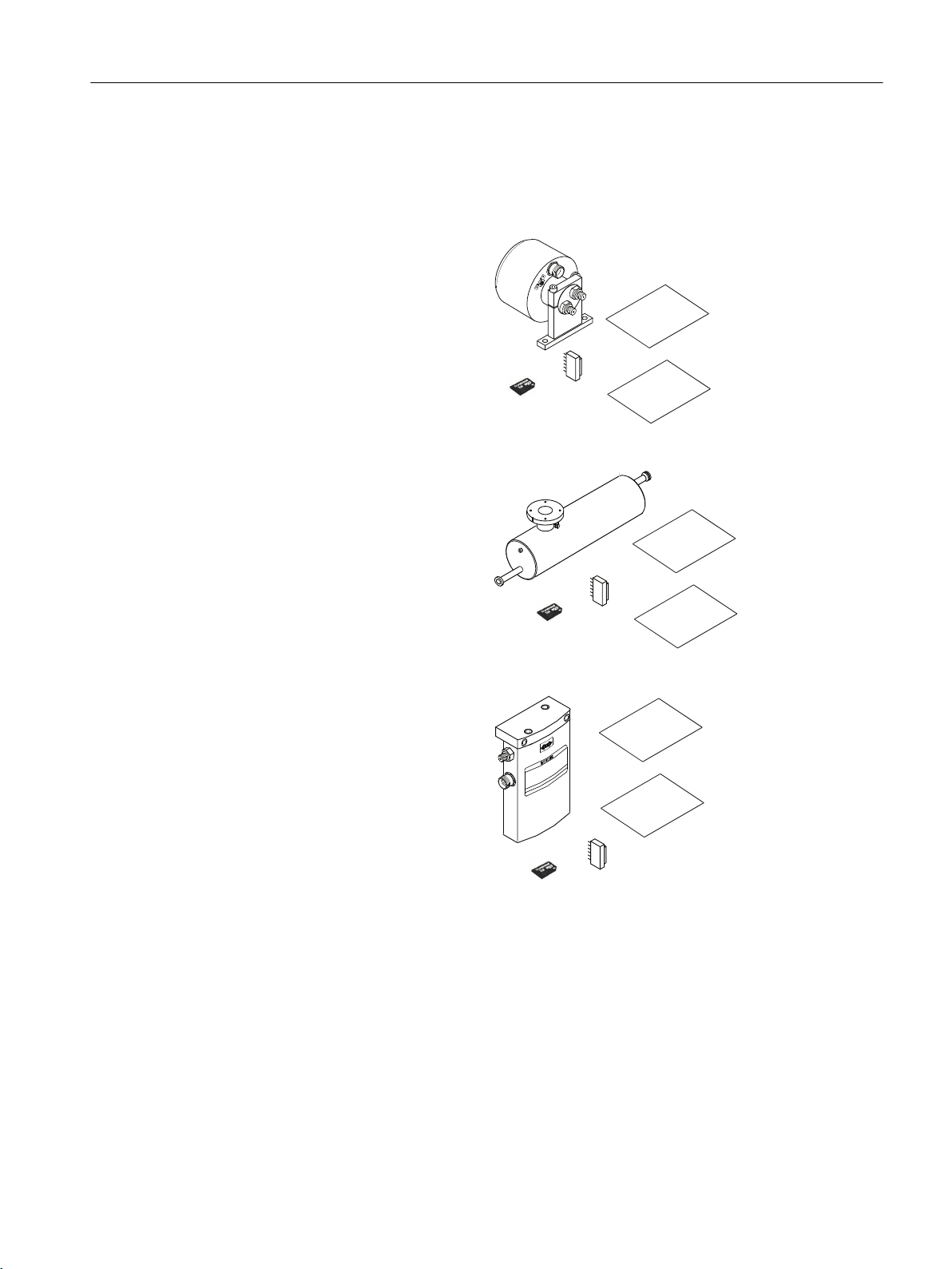
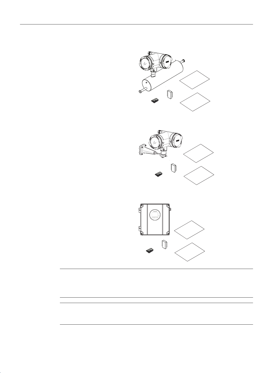
1.4 Items supplied
Safety N
ote
C
al.
rep.
Safety N
ote
C
al.
rep.
Safety N
ote
C
al.
rep.
Flowsensors
● MASS 2100 DI 1.0, DI 1.5, DI 2.1
● Sensorprom or SensorFlash
● Calibration report
● Calibration certificate
● MASS 2100 DI 3, DI 6, DI 15
● Sensorprom or SensorFlash
● Calibration report
● Calibration certificate
Introduction
1.4 Items supplied
● FC300 DN 4
● Sensorprom or SensorFlash
● Calibration report
● Calibration certificate
Flow transmitters:
● FCT010
● FCT030
● SIFLOW
● Calibration report
● Calibration certificate
MASS 2100 & FC300 (FCT030)
Operating Instructions, 06/2017, A5E39789040-AA 13
Page 14
Safety N
ote
C
al.
rep.
Safety N
ote
C
al.
rep.
Safety N
ote
C
al.
rep.
Introduction
1.4 Items supplied
Compact systems
● Packet of cable glands
● Calibration report
● Calibration certificate
● SensorFlash
(installed in FCT030 transmiiter)
Remote system
● Remote field mount
● Packet of cable glands
● Calibration report
● Calibration certificate
● Remote wall mount
● Packet of cable glands
● Calibration report
● Calibration certificate
Note
Supplementary information
Supplementary product and production specific certificates are included on the SensorFlash®
SD card in the transmitter socket.
Note
Scope of delivery may vary, depending on version and add-ons. Make sure the scope of
delivery and the information on the nameplate correspond to your order and the delivery note.
MASS 2100 & FC300 (FCT030)
14 Operating Instructions, 06/2017, A5E39789040-AA
Page 15

1.5 Checking the consignment
1. Check the packaging and the delivered items for visible damage.
2. Report any claims for damages immediately to the shipping company.
3. Retain damaged parts for clarification.
4. Check the scope of delivery by comparing your order to the shipping documents for
correctness and completeness.
WARNING
Using a damaged or incomplete device
Risk of explosion in hazardous areas.
● Do not use damaged or incomplete devices.
1.6 Security information
Siemens provides products and solutions with industrial security functions that support the
secure operation of plants, systems, machines, and networks.
Introduction
1.6 Security information
In order to protect plants, systems, machines and networks against cyber threats, it is
necessary to implement – and continuously maintain – a holistic, state-of-the-art industrial
security concept. Siemens’ products and solutions only form one element of such a concept.
Customer is responsible to prevent unauthorized access to its plants, systems, machines and
networks. Systems, machines and components should only be connected to the enterprise
network or the internet if and to the extent necessary and with appropriate security measures
(e.g. use of firewalls and network segmentation) in place.
Additionally, Siemens’ guidance on appropriate security measures should be taken into
account. For more information about industrial security, please visit:
http://www.siemens.com/industrialsecurity.
Siemens’ products and solutions undergo continuous development to make them more secure.
Siemens strongly recommends to apply product updates as soon as available and to always
use the latest product versions. Use of product versions that are no longer supported, and
failure to apply latest updates may increase customer’s exposure to cyber threats.
To stay informed about product updates, subscribe to the Siemens Industrial Security RSS
Feed under
http://www.siemens.com/industrialsecurity.
MASS 2100 & FC300 (FCT030)
Operating Instructions, 06/2017, A5E39789040-AA 15
Page 16

Introduction
1.7 Transportation and storage
1.7 Transportation and storage
To guarantee sufficient protection during transport and storage, observe the following:
● Keep the original packaging for subsequent transportation.
● Devices/replacement parts should be returned in their original packaging.
● If the original packaging is no longer available, ensure that all shipments are properly
packaged to provide sufficient protection during transport. Siemens cannot assume liability
for any costs associated with transportation damages.
NOTICE
Insufficient protection during storage
The packaging only provides limited protection against moisture and infiltration.
● Provide additional packaging as necessary.
Special conditions for storage and transportation of the device are listed in Technical data
(Page 215).
The contents of this manual shall not become part of or modify any prior or existing agreement,
commitment or legal relationship. The sales contract contains all obligations on the part of
Siemens as well as the complete and solely applicable warranty conditions. Any statements
regarding device versions described in the manual do not create new warranties or modify the
existing warranty.
The content reflects the technical status at the time of publishing. Siemens reserves the right
to make technical changes in the course of further development.
MASS 2100 & FC300 (FCT030)
16 Operating Instructions, 06/2017, A5E39789040-AA
Page 17

Safety notes
2.1 Preconditions for safe use
This device left the factory in good working condition. In order to maintain this status and to
ensure safe operation of the device, observe these instructions and all the specifications
relevant to safety.
Observe the information and symbols on the device. Do not remove any information or symbols
from the device. Always keep the information and symbols in a completely legible state.
Symbol Explanation
Consult operating instructions
Use the device only for flow measurement in accordance with this operating instruction and
observe the technical data.
WARNING
2
Improper device modifications
Risk to personnel, system and environment can result from modifications to the device,
particularly in hazardous areas.
● Only carry out modifications that are described in the instructions for the device. Failure
to observe this requirement cancels the manufacturer's warranty and the product
approvals.
Note
Functional safety applications (SIL)
If the device is used in a functional safety application, refer to the functional safety manual.
2.2 Laws and directives
Observe the safety rules, provisions and laws applicable in your country during connection,
assembly and operation. These include, for example:
● National Electrical Code (NEC - NFPA 70) (USA)
● Canadian Electrical Code (CEC) (Canada)
MASS 2100 & FC300 (FCT030)
Operating Instructions, 06/2017, A5E39789040-AA 17
Page 18

Safety notes
2.2 Laws and directives
Further provisions for hazardous area applications are for example:
● IEC 60079-14 (international)
● EN 60079-14 (EC)
2.2.1 FCC Conformity
US Installations only: Federal Communications Commission (FCC) rules
WARNING
Improper device modifications
Danger to personnel, system and environment can result from improper modifications to the
device.
● Changes or modifications not expressly approved by Siemens could void the user’s
authority to operate the equipment.
Note
● This equipment has been tested and found to comply with the limits for a Class A digital
device, pursuant to Part 15 of the FCC Rules. These limits are designed to provide
reasonable protection against harmful interference when the equipment is operated in a
commercial environment.
● This equipment generates, uses, and can radiate radio frequency energy and, if not installed
and used in accordance with the operating instructions, may cause harmful interference to
radio communications. Operation of this equipment in a residential area is likely to cause
harmful interference to radio communications, in which case the user will be required to
correct the interference at his own expense.
2.2.2 Conformity with European directives
The CE marking on the device symbolizes the conformity with the following European
directives:
Electromagnetic
compatibility EMC
2014/30/EU
Low voltage direc‐
tive LVD
2014/35/EU
18 Operating Instructions, 06/2017, A5E39789040-AA
Directive of the European Parliament and of the Council on the harmoni‐
sation of the laws of the Member States relating to electromagnetic com‐
patibility
Directive of the European Parliament and of the Council on the harmoni‐
sation of the laws of the Member States relating to the making available
on the market of electrical equipment designed for use within certain volt‐
age limits
MASS 2100 & FC300 (FCT030)
Page 19

Safety notes
2.3 Requirements for special applications
Atmosphère explosi‐
ble ATEX
2014/34/EU
Pressure equipment
directive PED
2014/68/EU
The applicable directives can be found in the EC conformity declaration of the specific device.
Note
CE declaration
The CE declaration certificate is available on the SensorFlash SD card delivered with the
device.
Directive of the European Parliament and the Council on the harmonisa‐
tion of the laws of the Member States relating to equipment and protective
systems intended for use in potentially explosive atmospheres
Directive of the European Parliament and of the Council on the approxi‐
mation of the laws of the Member States concerning pressure equipment
2.3 Requirements for special applications
Due to the large number of possible applications, each detail of the described device versions
for each possible scenario during commissioning, operation, maintenance or operation in
systems cannot be considered in the instructions. If you need additional information not
covered by these instructions, contact your local Siemens office or company representative.
Note
Operation under special ambient conditions
We highly recommend that you contact your Siemens representative or our application
department before you operate the device under special ambient conditions as can be
encountered in nuclear power plants or when the device is used for research and development
purposes.
MASS 2100 & FC300 (FCT030)
Operating Instructions, 06/2017, A5E39789040-AA 19
Page 20
Safety notes
2.4 Use in hazardous areas
2.4 Use in hazardous areas
2.4.1 Qualified personnel for hazardous area applications
Qualified personnel for hazardous area applications
Persons who install, connect, commission, operate, and service the device in a hazardous
area must have the following specific qualifications:
● They are authorized, trained or instructed in operating and maintaining devices and systems
according to the safety regulations for electrical circuits, high pressures, aggressive, and
hazardous media.
● They are authorized, trained, or instructed in carrying out work on electrical circuits for
hazardous systems.
● They are trained or instructed in maintenance and use of appropriate safety equipment
according to the pertinent safety regulations.
2.4.2 Use in hazardous areas
WARNING
Use in hazardous areas
Risk of explosion.
● Only use equipment that is approved for use in the intended hazardous area and labelled
accordingly.
2.4.3 Loss of safety of device with type of protection "Intrinsic safety Ex i"
WARNING
Loss of safety of device with type of protection "Intrinsic safety Ex i"
If the device has already been operated in non-intrinsically safe circuits or the electrical
specifications have not been observed, the safety of the device is no longer ensured for use
in hazardous areas. There is a risk of explosion.
● Connect the device with type of protection "Intrinsic safety" solely to an intrinsically safe
circuit.
● Observe the specifications for the electrical data on the certificate and/or in Technical
data (Page 215).
MASS 2100 & FC300 (FCT030)
20 Operating Instructions, 06/2017, A5E39789040-AA
Page 21

2.4.4 Installation in hazardous areas
WARNING
Equipment used in hazardous locations
Equipment used in hazardous locations must be Ex-approved for the region of installation
and marked accordingly. It is required that the special conditions for safe use provided in the
manual and in the Ex certificate are followed!
Hazardous area approvals
The device is approved for use in hazardous area and has the approvals listed below. Special
conditions for safe installation and operation specified by each approval authority are included
in the relevant certificate.
ATEX:
Safety notes
2.4 Use in hazardous areas
IECEx:
EAC Ex
CSA:
FCT030 field mount transmitter (can be installed in Zone 1 for gas and Zone 21 for dust):
Certificate: SIRA 11ATEX1342X
II 2(1) GD
Ex db eb [ia Ga] IIC T6 Gb Ta = -40°C to +60°C
Ex tb [ia Da] IIIC T85°C Db
FCT030 field mount transmitter (can be installed in Zone 1 for gas and Zone 21 for dust):
Certificate: IECEx SIR 11.0150X
Ex db eb ia [ia Ga] IIC T6 Gb Ta = -40°C to +60°C.
Ex tb [ia Da] IIIC T85°C Db
FCT030 field mount transmitter / -40°C ≤ Tamb ≤ +60°C
1Ex db eb ia [ia Ga] IIC T6 Gb
Ex tb [ia Da] IIIC T85°C Db
Ex Canada:
FCT030 field mount transmitter (can be installed in Zone 1 for gas and Zone 21 for dust):
Certificate: cCSAus 2508628
Ex db eb ia [ia Ga] IIC T6 Gb
Ex tb [ia Da] IIIC T85°C Db
MASS 2100 & FC300 (FCT030)
Operating Instructions, 06/2017, A5E39789040-AA 21
Page 22

Safety notes
2.4 Use in hazardous areas
For US:
FCT030 field mount transmitter (can be installed in Zone 1 for gas and Zone 21 for dust) and
Class I +II+III Group A, B, C, D, E, F:
Certificate: cCSAus 2508628
Class I, II, III Division 1 Gp A, B, C, D, E, F, G
Class I Zone 1: AEx db eb ia [ia Ga] IIC T6 Gb
Class II Zone 21: AEx tb [ia Da] IIIC T85°C Db
Installation variations
Note
Requirements for safe installation
● Standard remote installation with FCT030 because the connection is certified Intrinsically
Safe. however flameproof seals and conduit (for IS cable) can be used.
● Requirement for IS circuit is that the maximum input voltage Vi to DSL is 20 VDC, Ii is
maximum 484 mA, Pi < 2.3 W
FC300
ATEX Certificate : DEMKO 05 ATEX 138072X.
Sitrans FC300 can be used in zone 0.
Ex ia IIC T6…T3 Ga
IECEx Certificate: IECEx ULD 17.0030
Sitrans FC300 can be used in zone 0.
Ex ia IIC T6…T3 Ga
Canada Certificate. UL E232147
Sitrans FC300 can be used in zone 0 and Class I Division 1.
Class I Div. 1 Grp. A, B, C, D.
Ex ia IIC T6…T3 IIC Ga
US Certifikate. UL E232147
Sitrans FC300 can be used in zone 0 and Class I Division 1.
Class I Div. 1 Grp. A, B, C, D
AEx ia IIC T6…T3 IIC Ga
MASS 2100 & FC300 (FCT030)
22 Operating Instructions, 06/2017, A5E39789040-AA
Page 23

MASS 2100
Safety notes
2.4 Use in hazardous areas
ATEX Certificate : DEMKO 03 ATEX 135252X
Sitrans FC MASS 2100 can be used in zone 0, 20
Ex ia IIC T6…T3 Ga
Ex ia IIIC T135°C…T180°C Da
IECEx Certificate : IECEx ULD 17.0029
Sitrans FC MASS 2100 can be used in zone 0, 20
Ex ia IIC T6…T3 Ga
Ex ia IIIC T135°C…T180°C Da
Canada Certificate. UL E232147
Sitrans FC MASS 2100 can be used in zone 0, 20 and Class I+II+III Division 1. Grp. A,B,C,D,
E, F, G
Class I+II+III Division 1. Grp. A,B,C,D, E, F, G.
Ex ia IIC T6…T3 Ga
Ex ia IIIC T135°C…T180°C Da
US Certifikate: UL E232147
Sitrans FC MASS 2100 can be used in zone 0 and Class I Division 1.
Class I+II+III Division 1. Grp. A,B,C,D, E, F, G.
AEx ia IIC T6…T3 Ga
AEx ia IIIC T135°C…T180°C Da
2.4.5 Special conditions for safe use
Special conditions for safe use
In general, it is required that:
● The transmitter electronic compartment shall not be opened when energized and when an
explosive gas or dust atmosphere may be present.
● The terminal compartment may be opened when an explosive gas or dust atmosphere may
be present at any time. Access power terminals by lifting the cover only when de-energized.
● Appropriate cable connectors are used.
● Substitution of components may impair Intrinsic Safety.
MASS 2100 & FC300 (FCT030)
Operating Instructions, 06/2017, A5E39789040-AA 23
Page 24

Safety notes
2.4 Use in hazardous areas
● Sensor and transmitter are connected to the potential equalization throughout the
hazardous area.
● EN/IEC 60079-14 is considered for installation in hazardous areas.
Further information and instructions including approval-specific special conditions for safe use
in Ex applications can be found in the certificates on the accompanying literature CD and at
the product web page (www.siemens.com/FC430).
WARNING
Laying of cables
Explosion hazard
Cable for use in hazardous areas must satisfy the requirements for having a proof voltage of
at least 500 V AC applied between the conductor/ground, conductor/shield and shield/ground.
Connect the devices that are operated in hazardous areas as per the stipulations applicable
in the country of operation.
WARNING
Field wiring installation
Ensure that the national requirements of the country in which the devices are installed are
met.
2.4.6 Maximum temperature specifications for Ex use
MASS2100 remote sensor
Temperature classification with and without dust is related to the process temperature and
ambient temperature as listed below.
The maximum allowable process fluid temperatures with respect to temperature class for the
device when used with potentially explosive gases.
Max media temperature [°C] versus temperature classification (T-ambient: -20 to +50 °C)
Maximum Process Temperature per Temperature Class (°C)
Di1/1.5/2.1/3 Di6 Di15
T6 75 46 38
T5 100 100 100
T4 135 135 135
T3 180 180 180
Additionally, the maximum surface temperature of the overall device shall be:
● For dust application, maximum surface temperature = 135°C
● For media temperature above 135°C surface temperature = media temperature
MASS 2100 & FC300 (FCT030)
24 Operating Instructions, 06/2017, A5E39789040-AA
Page 25

For MASS 2100 compact with either FCT010 or FCT030
Safety notes
2.4 Use in hazardous areas
Ambient
Temperature
50°C 75 46 38 100 130 130
45°C 80 51 43 100 135 160
40°C 85 56 48 100 135 180
35°C 85 61 53 100 135 180
30°C 85 66 58 100 135 180
Maximum Process Temperature per Temperature Class (°C)
Di3 Di6 Di15
T6 T6 T6 T5 T4 T3
● For dust application, maximum surface temperature = 135°C
● For media temperature above 135°C surface temperature = media temperature
FC300
T3 for liquid temperatures from 135°C to 180°C.
T4 for liquid temperatures lower than 135°C.
T5 for liquid temperatures lower than 100°C.
T6 for liquid temperatures up to 65°C.
MASS 2100 & FC300 (FCT030)
Operating Instructions, 06/2017, A5E39789040-AA 25
Page 26

Safety notes
2.4 Use in hazardous areas
MASS 2100 & FC300 (FCT030)
26 Operating Instructions, 06/2017, A5E39789040-AA
Page 27

Description
3.1 Overview
SITRANS Coriolis flow meter systems consist of a transmitter and a sensor. The following
table lists the available combinations of transmitters and sensors.
Transmitter Sensor type
FCT030 MASS 2100
3.2 System configuration
3
FC300
The flowmeter can be used in a number of system configurations:
● as a field mounted transmitter and display supplied only with the necessary auxiliary power
● as part of a complex system environment, for example SIMATIC S7
MASS 2100 & FC300 (FCT030)
Operating Instructions, 06/2017, A5E39789040-AA 27
Page 28

Description
3.3 Design
3.3 Design
3.3.1 Applications
Measurement of liquids and gases
SITRANS F C Coriolis mass flowmeters are designed for measurement of a variety of liquids
and gases. The flowmeters are multi-parameter devices offering accurate measurement of
massflow, volumeflow, density, temperature and, depending on product variants, fraction,
including industry-specific fractions.
Main applications
The main applications of the Coriolis flowmeter can be found in all industries, such as:
● Chemical & Pharma: detergents, bulk chemicals, acids, alkalis, pharmaceuticals, blood
products, vaccines, insulin production
● Food & Beverage: dairy products, beer, wine, soft drinks, °Brix/°Plato, fruit juices and pulps,
bottling, CO2 dosing, CIP/SIP-liquids, mixture recipe control
● Automotive: fuel injection nozzle & pump testing, filling of AC units, engine consumption,
paint robots
● Oil & Gas: filling of gas bottles, furnace control, test separators, bore-hole plasticizer dosing,
water-cut metering
● Water & Waste Water: dosing of chemicals for water treatment
MASS 2100 & FC300 (FCT030)
28 Operating Instructions, 06/2017, A5E39789040-AA
Page 29

3.3.2 Versions
Versions
The SITRANS FC flowmeters uses the Coriolis principle to measure flow and is available in a
remote and a compact version.
● Compact version: The MASS2100 is a single mechanical unit where the transmitter is
directly mounted on the sensor.
● Remote version: The MASS2100 sensor unit is remotely connected to a SITRANS FCT
transmitter. Directly mounted on the sensor, its Digital Sensor Link (DSL) performs the
signal processing of all measured signals in the sensor. The 4-wire connection between
the transmitter and the sensor provides power and high-integrity digital communication
between the DSL and the transmitter.
Description
3.3 Design
Sensor design
Figure 3-1 Compact version
Figure 3-2 Remote version - M12 connection
All primary process measurement of massflow, volumeflow, density and process temperature
are made in the DSL/sensor front end.
The sensor comprises one single continuous bended tube, with no internal welds. The sensor
is available in an intrinsically safe (IS) design for hazardous area installations.
The sensors are available in AISI 316L stainless steel and Hastelloy C22. The enclosure is
made of AISI 316L stainless steel.
The sensor enclosure can be equipped with a pressure guard or flushed with dry inert gas at
the threaded ports for non-hazardous applications only.
In the remote configuration, the sensor front end (DSL) is available in an aluminum enclosure
with an ingress protection grade of IP67/NEMA 4X. For communication and power supply a 4-
MASS 2100 & FC300 (FCT030)
Operating Instructions, 06/2017, A5E39789040-AA 29
Page 30

Description
3.3 Design
Sensor overview
wire connection can be made via M12 plug and socket or cable gland/conduit entry for cable
termination.
① Earthing terminal
② Sensor enclosure
③ Plug and threaded port for e.g. pressure guard
Figure 3-3 Overview, remote and compact configuration
Transmitter design
The transmitter reads the primary values from the sensor and calculates derived values. It
provides up to four configurable I/Os. On channel 1, HART communication, PROFIBUS DP,
PROFIBUS PA or Modbus RTU RS485 is possible. On channel 2,3,4 each I/O can be
individually configured. A local display (human machine interface - HMI) is available, which
consists of a display and four buttons for user interaction. The transmitter adds functionalities
such as Standard volume flow, fractions, totalizers, dosing, access control, diagnostics,
configuration and logging.
The transmitter has a modular design with discrete, replaceable electronic modules and
connection boards to maintain separation between functions and facilitate field service. All
modules are fully traceable and their provenance is included in the transmitter setup.
30 Operating Instructions, 06/2017, A5E39789040-AA
MASS 2100 & FC300 (FCT030)
Page 31

Transmitter exploded view
D
E
D
/
E
Description
3.3 Design
① Display cover ⑫ Transmitter housing
② Local display (HMI) ⑬ Terminal space
③ Connector for HMI ⑭ Power supply terminal protection cover
④ SD card (SensorFlash) ⑮ Lid for terminal connections
⑤ DIP switch (for custody transfer) ⑯ Wiring tool
⑥ DIP switch (for HART and Modbus) ⑰ I/O cassette (optional)
⑦ HMI port ⑱ I/O configuration keys (optional)
⑧ USB service port ⑲a M12 socket
⑨ Transmitter cassette ⑲b Terminal housing
⑩ Heatsink cover for power supply module ⑳a Sensor module (compact version)
⑪ Cable entry ⑳b Barrier module (remote version)
Figure 3-4 Transmitter exploded view
MASS 2100 & FC300 (FCT030)
Operating Instructions, 06/2017, A5E39789040-AA 31
Page 32

Description
3.4 Features
3.4 Features
● The device can be used as HART slave in operation on SIEMENS SIMATIC S7/PCS7 or
third party automation systems
● Available in compact and remote design
● Full graphical local display (HMI)
● SensorFlash (SD card) for memory backup and documentation storage (certificates etc.)
● One current output a standard
– Channel 1: Current output with HART, Modbus, Profibus
The available process values for Channel 1 are restricted to those which are safety
certified: Massflow, Volumeflow and Density. For access to other process values,
including Process Temperature, an extra channel is required at ordering.
● Three optional input/output channels:
– Channel 2: Signal output; can be parameterized for:
Current output (0/4-20 mA)
Pulse output
Frequency output
One on/off valve output
Two on/off valves output
Alarm, status, flow direction
– Channels 3 and 4: Signal output (as channel 2)
Pulse or frequency redundancy mode ((only channel 3 linked to channel 2 with 90° or
180° redundancy))
– Channels 3 and 4: Relay output; can be parameterized as:
One on/off valve output
Two on/off valves output
Alarm, status, flow direction
– Channels 3 and 4: Signal input; can be parameterized as:
Dosing control
Totalizer control (resetting of totalizers)
Zero adjustment
Setting or freezing a frequency at the digital outputs if these are set to 'Frequency'
● Current, frequency, and pulse outputs with configurable fail safe mode
● High immunity against process noise
● Fast response to step changes in flow
● High update rate (100 Hz) on all process values
MASS 2100 & FC300 (FCT030)
32 Operating Instructions, 06/2017, A5E39789040-AA
Page 33

● Measurement of process values:
– Mass flow
– Volume flow
– Standard volume flow (including normalized gas flows)
– Density
– Process media temperature
– Fraction A (mass flow or volume flow)
– Fraction B (mass flow or volume flow)
– Fraction A %
– Fraction B %
● Configurable upper and lower alarms and warning limits for all process values
● Independent low flow cut-off settings for mass flow and volume flow
● Automatic zero-point adjustment (initiated by host system)
● Process noise damping using digital signal processing (DSP).
Description
3.4 Features
● Three totalizers for summation of massflow, volumeflow and corrected volumeflow,
depending on setting, of:
– Mass flow measurement
– Volume flow measurement
– Fraction A and B measurement (mass flow or volume flow)
– Corrected volumeflow
● Empty pipe monitoring
● Simulation of process values:
– Mass flow
– Volume flow
– Standard volume flow
– Density
– Process media temperature
– Fraction A %
– Fraction B %
– Sensor frame temperature
● Simulation of all outputs
● Simulation and suppression of alarms
● Comprehensive diagnostics (NAMUR or Siemens standard) for troubleshooting and sensor
checking
● Firmware update
● Use in hazardous locations according to specification
MASS 2100 & FC300 (FCT030)
Operating Instructions, 06/2017, A5E39789040-AA 33
Page 34

Description
3.7 Theory of operation
3.5 Applications
Measurement of liquids and gases
SITRANS F C Coriolis mass flowmeters are designed for measurement of a variety of liquids
and gases. The flowmeters are multi-parameter devices offering accurate measurement of
massflow, volumeflow, density, temperature and, depending on product variants, fraction,
including industry-specific fractions.
Main applications
The main applications of the Coriolis flowmeter can be found in all industries, such as:
● Chemical & Pharma: detergents, bulk chemicals, acids, alkalis, pharmaceuticals, blood
products, vaccines, insulin production
● Food & Beverage: dairy products, beer, wine, soft drinks, °Brix/°Plato, fruit juices and pulps,
bottling, CO2 dosing, CIP/SIP-liquids, mixture recipe control
● Automotive: fuel injection nozzle & pump testing, filling of AC units, engine consumption,
paint robots
● Oil & Gas: filling of gas bottles, furnace control, test separators, bore-hole plasticizer dosing,
water-cut metering
● Water & Waste Water: dosing of chemicals for water treatment
3.6 Approvals
Note
For further details see Approvals (Page 239).
The device is available with approvals for general purpose and for hazardous areas. In all
cases, check the nameplate on your device, and confirm the approval rating.
3.7 Theory of operation
The Coriolis principle of measurement
The flow measurement is based on the Coriolis law of motion. Particles moving in a rotating /
oscillating system will resist imposed oscillations in a manner consistent with their mass and
velocity (momentum). Oscillation produced by a Coriolis flowmeter where the process media
is accelerated around bends results in phase distortions of the measuring tubes.
The SITRANS F C sensors are energized by an electromagnetic (voice coil) driver circuit which
oscillates the pipes at their resonant frequency. Two pickups are placed symmetrically on either
side of the driver to provide position signals for digital processing.
MASS 2100 & FC300 (FCT030)
34 Operating Instructions, 06/2017, A5E39789040-AA
Page 35

)UHTXHQF\'HQVLW\
à
7LPH0$66IORZ
à
3LFNXS3LFNXS
Description
3.7 Theory of operation
When the media flows through the sensor, Coriolis force will act on the measuring tubes and
cause deflection which can be measured as a phase shift between Pickup 1 and Pickup 2.
The phase shift is proportional to the mass flowrate.
The frequency (or period) of the vibration is a direct function of the process media density.
The frequency and amplitude of the driver is regulated to ensure a stable output from the 2
pickups. The temperature of the sensor tubes is measured to provide accurate compensation
for changes in the material stiffness. As a result the process media temperature is also
accurately measured.
The flow proportional phase signal from the pickups, the temperature measurement and the
driver frequency enable calculation and reporting of mass, density, volume, and temperature.
Digital signal processing (DSP)
The analog to digital conversion takes place in an ultra low noise sigma delta converter with
high signal resolution. With fast digital signal processing massflow and density values are
calculated using a patented DFT technology (Discrete Fourier Transformation). The
combination of this patented DFT technology and the fast DSP enables short response time
(< 10 ms) to changes in the measured values.
The built-in noise filter is configurable and can be used for improving the performance of the
flowmeter, in case the installation and application conditions are not ideal. Typical process
noise such as gas bubbles (two-phase-flow) can be reduced through the filter functions.
MASS 2100 & FC300 (FCT030)
Operating Instructions, 06/2017, A5E39789040-AA 35
Page 36

Description
3.7 Theory of operation
MASS 2100 & FC300 (FCT030)
36 Operating Instructions, 06/2017, A5E39789040-AA
Page 37

Installing/mounting
4.1 Basic safety notes
CAUTION
Hot surfaces resulting from hot process media
Risk of burns resulting from surface temperatures above 70 °C (155 °F).
● Take appropriate protective measures, for example contact protection.
● Make sure that protective measures do not cause the maximum permissible ambient
temperature to be exceeded. Refer to the information in Technical data (Page 215).
WARNING
Wetted parts unsuitable for the process media
Risk of injury or damage to device.
Hot, toxic and corrosive media could be released if the process medium is unsuitable for the
wetted parts.
● Ensure that the material of the device parts wetted by the process medium is suitable for
the medium. Refer to the information in Technical data (Page 215).
4
Note
Material compatibility
Siemens can provide you with support concerning selection of sensor components wetted by
process media. However, you are responsible for the selection of components. Siemens
accepts no liability for faults or failures resulting from incompatible materials.
WARNING
Unsuitable connecting parts
Risk of injury or poisoning.
In case of improper mounting hot, toxic and corrosive process media could be released at
the connections.
● Ensure that connecting parts (such as flange gaskets and bolts) are suitable for connection
and process media.
MASS 2100 & FC300 (FCT030)
Operating Instructions, 06/2017, A5E39789040-AA 37
Page 38

Installing/mounting
4.1 Basic safety notes
Exceeded maximum permissible operating pressure
Risk of injury or poisoning.
The maximum permissible operating pressure depends on the device version, pressure limit
and temperature rating. The device can be damaged if the operating pressure is exceeded.
Hot, toxic and corrosive process media could be released.
Ensure that maximum permissible operating pressure of the device is not exceeded. Refer
to the information on the nameplate and/or in Technical data (Page 215).
Unprotected cable ends
Risk of explosion through unprotected cable ends in hazardous areas.
● Protect unused cable ends in accordance with IEC/EN 60079-14.
WARNING
WARNING
WARNING
Incorrect mounting at Zone 0
Risk of explosion in hazardous areas.
● Ensure sufficient tightness at the process connection.
● Observe the standard IEC/EN 60079-14.
WARNING
Loss of explosion protection
Risk of explosion in hazardous areas if the device is open or not properly closed.
● Close the device as described in Installing/mounting (Page 37).
CAUTION
External stresses and loads
Damage to device by severe external stresses and loads (e.g. thermal expansion or pipe
tension). Process media can be released.
● Prevent severe external stresses and loads from acting on the device.
MASS 2100 & FC300 (FCT030)
38 Operating Instructions, 06/2017, A5E39789040-AA
Page 39

4.1.1 Installation location requirements
NOTICE
Strong vibrations
Damage to device.
● In plants with strong vibrations, mount the transmitter in a low vibration environment.
CAUTION
Aggressive atmospheres
Damage to device through penetration of aggressive vapors.
● Ensure that the device is suitable for the application.
CAUTION
Direct sunlight
Installing/mounting
4.1 Basic safety notes
Device damage.
The device can overheat or materials become brittle due to UV exposure.
● Protect the device from direct sunlight.
● Make sure that the maximum permissible ambient temperature is not exceeded. Refer to
the information in Technical data (Page 215).
WARNING
Insufficient air supply
The device may overheat if there is an insufficient supply of air.
● Install the device so that there is sufficient air supply in the room.
● Observe the maximum permissible ambient temperature. Refer to the information in the
section Technical data (Page 215).
MASS 2100 & FC300 (FCT030)
Operating Instructions, 06/2017, A5E39789040-AA 39
Page 40

Installing/mounting
4.2 Installation instructions
4.1.2 Proper mounting
NOTICE
Incorrect mounting
The device can be damaged, destroyed, or its functionality impaired through improper
mounting.
● Before installing ensure there is no visible damage to the device.
● Make sure that process connectors are clean, and suitable gaskets and glands are used.
● Mount the device using suitable tools. Refer to the information in Construction
(Page 230) for installation torque requirements.
CAUTION
Loss of type of protection
Damage to device if the enclosure is open or not properly closed. The type of protection
specified on the nameplate or in Technical data (Page 215) is no longer guaranteed.
● Make sure that the device is securely closed.
4.2 Installation instructions
4.2.1 Sensor installation
4.2.1.1 Determining a location
CAUTION
Electromagnetic fields
Do not install the flowmeter in the vicinity of strong electromagnetic fields, for example near
motors, variable frequency drives, transformers etc.
Upstream / downstream
● No pipe run requirements, that is straight inlet/outlet sections are not necessary.
● Avoid long drop lines downstream from the sensor to prevent process media separation
causing air / vapor bubbles in the tube (min. back pressure: 0.2 bar).
● Avoid installing the flowmeter immediately upstream of a free discharge in a drop line.
MASS 2100 & FC300 (FCT030)
40 Operating Instructions, 06/2017, A5E39789040-AA
Page 41

Location in the system
The optimum location in the system depends on the application:
● Liquid applications
Gas or vapor bubbles in the fluid may result in erroneous measurements, particularly in the
density measurement.
– Do not install the flowmeter at the highest point in the system, where bubbles will be
– Install the flowmeter in low pipeline sections, at the bottom of a U-section in the pipeline.
● Gas applications
Vapor condensation or oil traces in the gas may result in erroneous measurements.
Installing/mounting
4.2 Installation instructions
trapped.
Figure 4-1 Liquid applications, wrong location with trapped air/gas
– Do not install the flowmeter at the lowest point of the system.
– Install a filter.
Figure 4-2 Gas applications, wrong location with trapped oil
4.2.1.2 Orientation of the sensor
Flow direction
The calibrated flow direction is indicated by the arrow on the sensor. Flow in this direction will
be indicated as positive by default. The sensitivity and the accuracy of the sensor do not change
with reverse flow.
The indicated flow direction (positive/negative) is configurable.
CAUTION
Accurate measurement
The sensor must always be completely filled with process media in order to measure
accurately.
MASS 2100 & FC300 (FCT030)
Operating Instructions, 06/2017, A5E39789040-AA 41
Page 42

Installing/mounting
4.2 Installation instructions
Orienting the sensor
The sensor operates in any orientation. The optimal orientation depends on the process fluid
and the process conditions. Siemens recommends orienting the sensor in one of the following
ways:
MASS 2100 DI 1.0, DI 1.5 and DI 2.1
Liquid applications
Horizontal installation, correct
Vertical installation, correct (liquids without solid
particles only)
Note
Air / gas bubbles in the liquid
Install the flowmeter horizontally
Note
Solid particles in the liquid
Install the flowmeter horizontally
Horizontal installation, correct
Vertical installation, wrong
MASS 2100 & FC300 (FCT030)
42 Operating Instructions, 06/2017, A5E39789040-AA
Page 43

Gas applications
Installing/mounting
4.2 Installation instructions
Liquid applications
Horizontal installation 1
Vertical installation 1
Horizontal installation, correct
Horizontal installation 2
Vertical installation 2
Horizontal installation, wrong
Vertical installation, correct Vertical installation, wrong
MASS 2100 & FC300 (FCT030)
Operating Instructions, 06/2017, A5E39789040-AA 43
Page 44

Installing/mounting
4.2 Installation instructions
Gas applications
Horizontal installation
Installation in a drop line
Installation in a dropline is only possible if a pipeline reduction or orifice with a smaller crosssection can be installed to prevent the sensor from being partially drained during the
measurements.
Vertical installation (not recommended)
① Orifice Pipe
② Valve
Figure 4-3 Installation in drop line
MASS 2100 & FC300 (FCT030)
44 Operating Instructions, 06/2017, A5E39789040-AA
Page 45

WARNING
Unsuitable connecting parts
Risk of injury or poisoning.
In case of improper mounting hot, toxic and corrosive process media could be released at
the connections.
● Ensure that connecting parts (such as flange gaskets and bolts) are suitable for connection
and process media.
4.2.1.3 Mounting the sensor
● Install the sensor in well-supported pipelines in order to support the weight of the
flowmeter.
Installing/mounting
4.2 Installation instructions
Avoid vibrations
Figure 4-4 Avoid vibrations
● Center the connecting pipelines axially in order to assure a stress-free installation. The
flowmeter must not be used to bring the rest of the pipework into line; make sure the
pipework is correctly aligned before inserting the flow sensor.
● Install two supports or hangers symmetrically and stress-free on the pipeline in close
proximity to the process connections.
Note
Handling
Never lift the flowmeter using the housing, that is always lift the sensor body.
● Make sure that any valves or pumps upstream of the sensor do not cavitate and do not
send vibrations into the sensor.
● Decouple vibrating pipeline from the flow sensor using flexible tube or couplings.
MASS 2100 & FC300 (FCT030)
Operating Instructions, 06/2017, A5E39789040-AA 45
Page 46

Installing/mounting
4.2 Installation instructions
Figure 4-5 AvoNon-flexible pipes not recommended in vibrating environment
Avoid cross talk
Figure 4-6 Flexible pipes recommended in vibrating environment
If operating more than one flowmeter in one or multiple interconnected pipelines there is a risk
of cross talk.
MASS 2100 & FC300 (FCT030)
46 Operating Instructions, 06/2017, A5E39789040-AA
Page 47

Prevent cross talk in one of the following ways:
● Mount sensors on separate frames
● Decouple the pipeline using flexible tube or couplings
High risk of cross talk when using non-flexible pipes
Installing/mounting
4.2 Installation instructions
Low risk of cross talk when using flexible pipes and separate frames
4.2.1.4 Hydrostatic testing
The flowmeter is pressure-tested before delivery to 1.5 times the rated working pressure of
the sensor.
● In the case of process connections pressure-rated less than 100 bar, the connection is the
limiting component.
● In the case of process connections pressure-rated above 100 bar (stainless steel sensors)
or above 160 bar (Hastelloy sensors), the sensor is the limiting component.
In all cases the maximum allowed hydrostatic test pressure (MATP) of the flowmeter is 1.5
times the marked MAWP (PS) at 20 °C.
Pressure test of a completed flow system with piping and other components can be done at
pressures no higher than 1.5 times the marked MAWP (PS) at 20 °C of the lowest rated system
component.
MASS 2100 & FC300 (FCT030)
Operating Instructions, 06/2017, A5E39789040-AA 47
Page 48

Installing/mounting
4.2 Installation instructions
4.2.1.5 Process pipe connection
The process pipes can be mounted directly onto the process connections on the sensor. To
obtain a proper scaling, use a wrench on the base of the process connections as counter lock
to secure with the optimum torque.
4.2.1.6 Mounting a pressure guard
CAUTION
Avoid moisture, liquids or particles getting into the sensor enclosure
All sensors are filled with argon to avoid condensation. Penetration of humidity, liquids or
particles into the sensor may influence the measurement and in worst case affect the
measuring function.
Install a pressure guard as follows:
1. Place the sensor in a dry, clean place and leave it to acclimatize until it reaches ambient
temperature, preferred 20°C (68°F).
2. Carefully disconnect the nipple and mount the pressure guard. Use the enclosed spare part
sealing ring for proper sealing.
3. Make sure that the pressure guard does NOT touch any of the parts inside the sensor.
4. Check that the pressure guard has been correctively mounted and thoroughly tightened.
After dismantling the sealing ring must be replaced with a new sealing ring.
Pressure guards are not supplied with the sensor.
Before removing the nipple from the sensor enclosure, please note the following:
MASS 2100 & FC300 (FCT030)
48 Operating Instructions, 06/2017, A5E39789040-AA
Page 49

Installing/mounting
4.2 Installation instructions
Penetration of humidity, liquids, or particles into the sensor must be avoided as it may influence
the measurement and, in worst case, affect the measuring function. Influence, however, can
be avoided using the following:
1. Place the sensor in a dry, clean place and leave it to acclimatize until it reaches ambient
temperature, preferred 20°C (68°F).
2. Carefully remove the plug and mount the pressure guard. Use replacement soft metal
sealing rings for proper sealing.
3. Check that the pressure guard has been correctly mounted and thoroughly tightened so
that the sealing ring fits tightly. After each dismantling, the sealing ring must always be
replaced by a new one.
Principle
Pressure guard selection
Siemens does not supply the components of the pressure guard solution because the
arrangement and components are closely related to individual safety and protection practices
in each place.
The selection of pressure guard solution is the responsibility of the user, however Siemens
recommends the following forms of pressure guard:
● A pressure switch screwed directly or piped into one of the purge ports and connected to
an automatic shut-off valve will disable pressurized supply to the meter.
● A relief valve or bursting disc screwed directly or piped to one of the purge ports to carry
any spilt fluid to drain after opening.
The pressure switch and relief valve set point should be 2-3 bar gauge. The pressure switch
should be rated to withstand the full process pressure and temperature for a short time without
rupture.
CAUTION
Drain flow
Ensure the drain flow is safely contained away from personnel and other plant or equipment.
MASS 2100 & FC300 (FCT030)
Operating Instructions, 06/2017, A5E39789040-AA 49
Page 50

Installing/mounting
4.2 Installation instructions
Mounting of pressure guard
CAUTION
Moisture, liquids or particles getting into the sensor enclosure
All sensors are filled with argon to avoid condensation. Ingress of moisture, liquids or particles
into the sensor may influence the measurement and in worst case inhibit the measuring
function.
● Avoid moisture, liquids or particles getting into the sensor enclosure
Install a pressure guard as follows:
1. Place the sensor in a dry, clean place and leave it to acclimatize until it reaches ambient
temperature, preferred 20°C (68°F) with low humidity (at least below 50% RH).
2. Orient the sensor with the purge ports uppermost to minimize loss of the argon gas filling.
3. Carefully remove the plug and mount the pressure guard.
Use replacement soft metal sealing rings for proper sealing.
CAUTION
Lack of proper sealing
Soft metal sealing rings only maintain a hermetic seal within the enclosure with single use.
● Ensure that soft metal sealing rings are not reused.
4. Make sure that the pressure guard does NOT touch any of the parts inside the sensor.
Maximum of 20 mm (0.79") insertion can be accommodated.
5. Check that the pressure guard has been correctly mounted and thoroughly tightened.
WARNING
Operation in proximity with pressure guards
Prevent personal injuries by assuring that operation in close proximity with pressure
guards cannot take place.
4.2.2 Transmitter installation
This chapter describes how to install the transmitter on a wall or pipe (remote configurations
only). The chapter further describes how to turn the transmitter or the local display in order to
optimize the viewing angle.
The following installation steps must be carried out:
1. Install the mounting bracket on a wall or pipe.
2. Install the transmitter on the mounting bracket.
3. Turn the transmitter and/or turn the local display (optional).
MASS 2100 & FC300 (FCT030)
50 Operating Instructions, 06/2017, A5E39789040-AA
Page 51

4.2.2.1 Remote transmitter mounting
Mounting on wall
1. Prepare holes with aid of mounting bracket, see Mounting bracket (Page 257).
2. Fasten mounting bracket with black cushion pad to wall (torque 10 Nm).
Mounting on pipe
1. Mount mounting bracket with cushion pad on pipe using fastening brackets/U-bolts and
supplied pipe adaptor. Note: U-bolts and other miscellaneous hardware are not supplied
with the flowmeter.
Installing/mounting
4.2 Installation instructions
2. Tighten nuts (torque: 10 Nm).
Note
Hygienic applications
If the device is wall or pipe-mounted in a hygienic application, always use domed nuts.
MASS 2100 & FC300 (FCT030)
Operating Instructions, 06/2017, A5E39789040-AA 51
Page 52

r
r
Installing/mounting
4.2 Installation instructions
Mounting the transmitter
1. Remove locking cap from mounting bracket.
2. Mount transmitter on mounting bracket taking care that the flutes on the mating faces are
correctly engaged.
3. Firmly tighten locking cap on mounting bracket (torque: 25 Nm).
Turning the transmitter
Horizontal rotation
In a remote configuration, the transmitter can be turned horizontally and tilted vertically.
1. Unscrew cap from lock screw.
2. Loosen lock screw at transmitter pedestal using 5 mm Allen key.
3. Carefully rotate transmitter into desired position.
4. Firmly tighten lock screw (torque: 10 Nm).
5. Replace cap onto lock screw (torque: 10 Nm).
52 Operating Instructions, 06/2017, A5E39789040-AA
MASS 2100 & FC300 (FCT030)
Page 53

Vertical rotation
1. Loosen locking cap at end of mounting bracket by three turns.
2. Carefully loosen and rotate transmitter into desired position (15° steps).
3. Firmly tighten locking cap (torque: 25 Nm).
4.2.2.2 Turning the local display
Installing/mounting
4.2 Installation instructions
The local display can be turned in steps of 30° in order to optimize the viewing angle.
1. Remove lid lock screw of display cover.
2. Remove display cover.
3. Use a small screwdriver or blade to loosen the three retaining clips within the transmitter.
4. Carefully pull out local display.
5. Turn display into desired position.
MASS 2100 & FC300 (FCT030)
Operating Instructions, 06/2017, A5E39789040-AA 53
Page 54

Installing/mounting
4.2 Installation instructions
6. Carefully push display back into housing. Use a small screwdriver or blade to open the
three retaining clips within the transmitter when pushing the display home.
7. Remove O-ring from lid.
8. Reinstall display cover until mechanical stop. Wind back lid by one turn.
9. Mount O-ring by pulling it over the display cover and turn display cover until you feel friction
from the O-ring on both sides. Wind display cover further by one quarter of a turn to seal
on the O-ring.
10.Reinstall and tighten lid lock screw.
4.2.2.3 Wall mount housing transmitter
CAUTION
Opening lid
Care must be taken when opening the lid to avoid the lid falling.
MASS 2100 & FC300 (FCT030)
54 Operating Instructions, 06/2017, A5E39789040-AA
Page 55

Mounting on wall
PPರ
PPರ
Mounting on wall
Installing/mounting
4.2 Installation instructions
1. Prepare holes for the four screws (M6x100 or equivalent). Screw head diameter: max. 13.5
mm; screw shaft diameter: max. 6 mm.
2. Mount transmitter and tighten screws.
MASS 2100 & FC300 (FCT030)
Operating Instructions, 06/2017, A5E39789040-AA 55
Page 56

Installing/mounting
4.3 Disassembly
4.3 Disassembly
WARNING
Incorrect disassembly
The following risks may result through incorrect disassembly:
- Injury through electric shock
- Risk through emerging media when connected to the process
- Risk of explosion in hazardous area
In order to disassemble correctly, observe the following:
● Before starting work, make sure that you have switched off all physical variables such as
pressure, temperature, electricity etc. or that they have a harmless value.
● If the device contains hazardous media, it must be emptied prior to disassembly. Make
sure that no environmentally hazardous media are released.
● Secure the remaining connections so that no damage can result if the process is started
unintentionally.
MASS 2100 & FC300 (FCT030)
56 Operating Instructions, 06/2017, A5E39789040-AA
Page 57

Connecting
5.1 Basic safety notes
WARNING
Unsuitable cables, cable glands and/or plugs
Risk of explosion in hazardous areas.
● Use only cable glands/plugs that comply with the requirements for the relevant type of
protection.
● Tighten the cable glands in accordance with the torques specified in Technical data
(Page 215).
● Close unused cable inlets for the electrical connections.
● When replacing cable glands use only cable glands of the same type.
● After installation check that the cables are seated firmly.
WARNING
Incorrect conduit system
5
Risk of explosion in hazardous areas as result of open cable inlet or incorrect conduit system.
● In the case of a conduit system, mount a spark barrier at a defined distance from the device
input. Observe national regulations and the requirements stated in the relevant approvals.
WARNING
Hazardous contact voltage
Risk of electric shock in case of incorrect connection.
● For the electrical connection specifications, refer to the information in Technical data
(Page 215).
● At the mounting location of the device observe the applicable directives and laws for
installation of electrical power installations with rated voltages below 1000 V.
NOTICE
Condensation in the device
Damage to device through formation of condensation if the temperature difference between
transportation or storage and the mounting location exceeds 20 °C (36 °F).
● Before taking the device into operation let the device adapt for several hours in the new
environment.
MASS 2100 & FC300 (FCT030)
Operating Instructions, 06/2017, A5E39789040-AA 57
Page 58

Connecting
5.1 Basic safety notes
Missing PE/ground connection
Risk of electric shock.
Depending on the device version, connect the power supply as follows:
● Power plug: Ensure that the used socket has a PE/ground conductor connection. Check
● Connecting terminals: Connect the terminals according to the terminal connection
NOTICE
Ambient temperature too high
Damage to cable sheath.
● At an ambient temperature ≥ 60 °C (140 °F), use heat-resistant cables suitable for an
WARNING
that the PE/ground conductor connection of the socket and power plug match each other.
diagram. First connect the PE/ground conductor.
ambient temperature at least 20 °C (36 °F) higher.
WARNING
Improper power supply
Risk of explosion in hazardous areas as result of incorrect power supply, e.g. using direct
current instead of alternating current.
● Connect the device in accordance with the specified power supply and signal circuits. The
relevant specifications can be found in the certificates, in Technical data (Page 215) or on
the nameplate.
WARNING
Unsafe extra-low voltage
Risk of explosion in hazardous areas due to voltage flashover.
● Connect the device to an extra-low voltage with safe isolation (SELV).
WARNING
Lack of equipotential bonding
Risk of explosion through compensating currents or ignition currents through lack of
equipotential bonding.
● Ensure that the device is potentially equalized.
Exception: It may be permissible to omit connection of the equipotential bonding for devices
with type of protection "Intrinsic safety Ex i".
MASS 2100 & FC300 (FCT030)
58 Operating Instructions, 06/2017, A5E39789040-AA
Page 59

Connecting
5.1 Basic safety notes
WARNING
Unprotected cable ends
Risk of explosion through unprotected cable ends in hazardous areas.
● Protect unused cable ends in accordance with IEC/EN 60079-14.
WARNING
Improper laying of shielded cables
Risk of explosion through compensating currents between hazardous area and the
non‑hazardous area.
● Shielded cables that cross into hazardous areas should be grounded only at one end.
● If grounding is required at both ends, use an equipotential bonding conductor.
WARNING
Uncovered non-intrinsically safe circuits
Risk of explosion in hazardous areas or electric shock when working on non-intrinsically safe
circuits.
If intrinsically safe and non-intrinsically safe circuits are operated in an enclosure with the
type of protection "Increased safety Ex e", the connections of the non-intrinsically safe circuits
must be additionally covered.
● Ensure that the cover of the non-intrinsically safe circuits complies with degree of
protection IP30 or higher according to IEC/EN 60529.
● Separate connections of the non-intrinsically safe circuits in accordance with IEC/
EN 60079-14.
WARNING
Insufficient isolation of intrinsically safe and non-intrinsically safe circuits
Risk of explosion in hazardous areas.
● When connecting intrinsically safe and non‑intrinsically safe circuits ensure that isolation
is carried out properly in accordance with local regulations for example IEC 60079-14.
● Ensure that you observe the device approvals applicable in your country.
MASS 2100 & FC300 (FCT030)
Operating Instructions, 06/2017, A5E39789040-AA 59
Page 60

Connecting
5.1 Basic safety notes
Connecting device in energized state
Risk of explosion in hazardous areas.
● Connect devices in hazardous areas only in a de-energized state.
Exceptions:
● Devices having the type of protection "Intrinsic safety Ex i" may also be connected in
● Exceptions for type of protection "Non-sparking nA" (Zone 2) are regulated in the relevant
Incorrect selection of type of protection
Risk of explosion in areas subject to explosion hazard.
This device is approved for several types of protection.
1. Decide in favor of one type of protection.
2. Connect the device in accordance with the selected type of protection.
3. In order to avoid incorrect use at a later point, make the types of protection that are not
WARNING
energized state in hazardous areas.
certificate.
WARNING
used permanently unrecognizable on the nameplate.
Note
Electromagnetic compatibility (EMC)
You can use this device in industrial environments, households and small businesses.
For metal housings there is an increased electromagnetic compatibility compared to highfrequency radiation. This protection can be increased by grounding the housing, see Basic
safety notes (Page 57).
Note
Improvement of interference immunity
● Lay signal cables separate from cables with voltages > 60 V.
● Use cables with twisted wires.
● Keep device and cables at a distance from strong electromagnetic fields.
● Take account of the conditions for communication specified in the Technical data
(Page 215).
● HART: Use shielded cables to guarantee the full specification according to HART.
MASS 2100 & FC300 (FCT030)
60 Operating Instructions, 06/2017, A5E39789040-AA
Page 61

5.1.1 Energized devices
WARNING
Energized devices
Risk of electric shock or explosion.
When energized the device may be opened by qualified personnel only.
WARNING
Mains supply from building installation overvoltage category 2
A switch or circuit breaker (max. 15 A) must be installed in close proximity to the equipment
and within easy reach of the operator. It must be marked as the disconnecting device for the
equipment.
Connecting
5.1 Basic safety notes
5.1.2 Safety notes for connecting
Use in hazardous areas
Before accessing the sensor terminal compartment and application terminal space check that:
● A safe access permission certificate has been issued by plant operations management
● The flow transmitter may not be opened if energized
● All connection leads are potential free
WARNING
Hazardous areas
Observe the type examination certificates or the test certifications applicable in your country
if you use transmitters as category 1/2 equipment.
WARNING
Commissioning
Only apply power and commission the device after the device has been properly connected
and, if required, closed.
MASS 2100 & FC300 (FCT030)
Operating Instructions, 06/2017, A5E39789040-AA 61
Page 62

Connecting
5.2 Connecting MASS 2100/FC300
5.1.3 Lack of equipotential bonding
WARNING
Lack of equipotential bonding
Danger of explosion through compensating currents or ignition currents through lack of
equipotential bonding.
● Ensure that the device is potentially equalized.
5.2 Connecting MASS 2100/FC300
This chapter describes how to wire up the device.
The following steps must be carried out:
● Step 1: Connecting the DSL and the transmitter (Page 64) (only remote version)
See also
● Step 2: Preparing for the transmitter connections (Page 68)
● Choose the following connection to either HART, Modbus or Profibus
– Connecting the Current HART, CH1 (Page 70)
– Connecting the Profibus (CH1) (Page 74)
– Connecting the Modbus (CH1) (Page 73)
● Step 3: Connecting the power supply (Page 75)
● Step 5: Finishing the transmitter connection (Page 81)
Step 4b: Connecting the inputs and outputs (channels 2 to 4) (Page 78)
MASS 2100 & FC300 (FCT030)
62 Operating Instructions, 06/2017, A5E39789040-AA
Page 63

5.2.1 Cable requirements
Cable specifications
● When installing sensor cable, use cable with at least same degree of protection as the
sensors. It is recommended to use cables supplied by Siemens:
– blue cables for installation of intrinsically safe circuits in hazardous areas
– gray cables for installation of non-intrinsically safe circuits
Further information on Siemens-supplied cables, see Technical data (Page 215).
● The wire length inside the connection compartment, from the cable gland to the terminals,
must be kept as short as possible. Wire loops in the terminal compartment must be avoided.
● To guarantee the degree of ingress protection, ensure that both ends of the cables are
given equivalent protection from ingress of moisture.
WARNING
Cable requirements
Connecting
5.2 Connecting MASS 2100/FC300
Cables must be suitable for the temperature (at least 70 °C) and be flammability-rated to at
least V-2.
Note
Output cables
If long cables are used in noisy environments, it is recommended to use shielded cables.
Electrical connection, Analog sensor wiring
5.2.2 Connection safety information
WARNING
Tightness
Only when the cable is connected to the sensor, the IP67 protection is achived.
MASS 2100 & FC300 (FCT030)
Operating Instructions, 06/2017, A5E39789040-AA 63
Page 64

Connecting
5.2 Connecting MASS 2100/FC300
WARNING
Installation in hazardous areas
When making electrical connections, observe the national statutes and provisions for
hazardous areas valid for the particular country.
● Operational safety regulations
● Directive for the installation of electrical systems in hazardous areas DIN EN 60079-14
5.2.3 Connecting the multiple plug to the sensor
When connecting/disconnecting the pipes, the cable must be mechanically connected in order
to prevent the liquid from penetrating into the electrical multiple plug on the sensor.
Mount the multiple plug and tighten the glands for optimum sealing.
5.2.4 Transmitter power supply and I/Os connection
5.2.4.1 Step 1: Connecting the DSL and the transmitter
The following only applies to remote configurations.
Wiring DSL (sensor) and transmitter (M12)
The DSL is provided with a preformed cable terminated with M12 style stainless steel weatherproof plugs.
MASS 2100 & FC300 (FCT030)
64 Operating Instructions, 06/2017, A5E39789040-AA
Page 65

The cable screen is physically and electrically terminated within the body of the plug.
PP
/
PPPP
2UDQJH
<HOORZ
:KLWH
%OXH
Take care when handling the cable and passing it through cable ducting that the plug is not
subjected to excessive tension (pulling) as the internal connections may be disengaged.
Note
Never pull the cable by the plug - only by the cable itself.
1. Connect DSL using the supplied 4-wire cable with M12 connectors.
Note
Grounding
The DSL cable screen is mechanically connected to the grounding terminal (PE), only when
the M12 plug is correctly tightened.
Wiring sensor and transmitter (sensor terminal compartment)
A: Prepare the cable by stripping it at both ends.
Connecting
5.2 Connecting MASS 2100/FC300
Figure 5-1 Cable end
B: Connecting sensor terminal compartment
1. Remove lock screw and remove lid.
2. Remove one of the blind plugs and fit cable gland.
3. Remove cap and ferrule from cable gland and slide onto cable.
4. Push cable through open gland; anchor cable with clamp bar. Ensure that the clamp does
not earth the screen. Apply heat-shrink sleeve to make sure the screen is only earthed at
the sensor end.
MASS 2100 & FC300 (FCT030)
Operating Instructions, 06/2017, A5E39789040-AA 65
Page 66

Connecting
5.2 Connecting MASS 2100/FC300
5. Connect wires to terminals according to list below.
Terminal number Description Wire color (Siemens)
1 0+ Orange
2 0 V Yellow
3 RS485 / B White
4 RS485 / A Blue
6. Assemble and tighten cable gland
7. Remove O-ring from lid.
8. Reinstate lid and screw in until mechanical stop. Wind back lid by one turn.
9. Mount O-ring by pulling it over the lid and tighten lid until you feel friction from the O-ring
on both sides. Wind lid further by one quarter of a turn to seal on the O-ring.
10.Reinstate and tighten lid lock screw
Connecting sensor DSL
1. Remove lock screw and remove DSL lid.
2. Undo the flexible strap.
3. Disconnect sensor connection from DSL cassette.
4. Loosen mounting screw using a TX10 Torx driver and remove DSL cassette from housing.
5. Remove cap and ferrule from cable gland and slide onto cable.
6. Push cable through open gland; anchor cable screen and wires with clamp bar.
7. Remove terminal block from DSL cassette.
MASS 2100 & FC300 (FCT030)
66 Operating Instructions, 06/2017, A5E39789040-AA
Page 67

21
2))
5.2 Connecting MASS 2100/FC300
8. Connect wires to terminals according to list below.
Terminal number Description Wire color (Siemens cable)
1 0+ Orange
2 0 V Yellow
3 RS485 / B White
4 RS485 / A Blue
Connecting
9. Ensure the DIP switches are all set to OFF.
10.Reinstate DSL cassette including mounting screw.
11.Connect sensor connection and sensor cable plugs.
12.Restore flexible strap around all wires.
13.Assemble and tighten cable gland.
14.Remove O-ring from DSL lid.
15.Reinstate lid and screw in until mechanical stop. Wind back lid by one turn.
16.Mount O-ring by pulling it over the DSL lid and tighten lid until you feel friction from the O-
ring on both sides. Wind lid further by one quarter of a turn to seal on the O-ring.
17.Reinstate and tighten lid lock screw.
18.Close and secure DSL lid including lock screw. Turn the lid until you can feel the friction of
the O-ring. From this point turn the lid ¼ turn to be tight.
MASS 2100 & FC300 (FCT030)
Operating Instructions, 06/2017, A5E39789040-AA 67
Page 68

2
3
1
Connecting
5.2 Connecting MASS 2100/FC300
5.2.4.2 Step 2: Preparing for the transmitter connections
WARNING
Access to terminal compartment
As long as the device is energized, the lid of the housing on the sensor connection area may
only be opened by qualified personnel.
Before removing the terminal cover, the auxiliary power must be switched off from all poles.
Following installation, the terminal cover must be screwed back on again.
1. Remove blind plugs where required and mount cable glands.
① Input/output connection (channels 2 to 4)
② Power supply connection
③ Current output/communication outputs (channel 1)
2. Remove lid lock screw for terminal connections lid.
3. Remove lid for terminal connections.
A label showing the configuration is placed at the back of the terminal connections lid.
MASS 2100 & FC300 (FCT030)
68 Operating Instructions, 06/2017, A5E39789040-AA
Page 69

Channel (Ch)
Function
Description
1
Current Output
- 4 to 20 mA,
RL <500 Ohm (HART ≥230 Ohm)
Active: Vo=28 V, Io=87mA
Passive : Vi=30 V DC, Ii=100 mA
2
Signal Output
- C: 0/4 to 20 mA
- F: fmax 10 kHz
RL <500 Ohm
Active: Vo=28 V, Io= 87 mA
Passive: Vi=30 V DC, Ii=100 mA
3
Signal Input
Active: Vo=28 V, Io=87 mA
Passive : Vi=30 V DC, Ii=100 mA
P
4
Relay Output
)&
3RZHUVXSSO\
/ 7HUPLQDO
17HUPLQDO
7HUPLQDO
$$FWLYH
33DVVLYH
121RUPDOO\RSHQFRQWDFW
1&1RUPDOO\FORVHGFRQWDFW
):UHYLVLRQ
+:UHYLVLRQ
'DWH
8SGDWH
8SGDWH
6HH2SHUDWLQJ,QVWUXFWLRQV
5 (+) / 6 (-)
9 (+) / 10 (-)
12 (+) / 13 (-)
14/15:15/16
6LHPHQV$6)ORZ,QVWUXPHQWV1RUGERUJ'HQPDUN
0DGHLQ'HQPDUN
6HULDOQR)'.&
9L 9'&,L P$
1&12
7HUPLQDOV
+$57DGGU
P
P
&D
&E
&F
&G
&K&
&K
&K
&K&
&K
&K
&K&
&K
&K
/
1
Connecting
5.2 Connecting MASS 2100/FC300
① Power supply con‐
nections
L/+ Terminal 1
N/- Terminal 2
Terminal 3
② Key to symbols A Configured as active input/output
P Configured as passive input/output
NO Connected as normally open contact
NC Connected as normally closed contact
③ Updates (to be filled in on firmware and hardware updates)
④ Device configuration date
⑤ Initial firmware and hardware revisions
⑥ Configuration of channels 1, 2, 3 and 4
Figure 5-2 Configuration label
Terminal layout
Field mount version Wall box version
MASS 2100 & FC300 (FCT030)
Operating Instructions, 06/2017, A5E39789040-AA 69
For configuration of the inputs/outputs, see table in section Step 4b: Connecting the inputs
and outputs (channels 2 to 4) (Page 78).
Page 70

3RZHU6XSSO\&KDQQHO
&KDQQHO
&KDQQHO&KDQQHO
7HUPLQDOV
/1
$FWLYH
1&
12
1&
12
3RZHU6XSSO\
&KDQQHO0RGEXV
&KDQQHO3URILEXV
&KDQQHO2XWSXW
2XWSXWV&XUUHQW)UHTXHQF\3XOVHDQGVWDWXV
,QSXWV'LJLWDO
&XUUHQWRXWSXW+$57
&XUUHQW)UHTXHQF\
3XOVHDQG6WDWXV
&KDQQHO+$57
6:FRQILJXUDWLRQ+:FRQILJXUDWLRQ
&KDQQHOVDQG
,QSXWRXWSXW
&KDQQHOVDQG
5HOD\
6WDWXVRXWSXW
&RPPRQ
&RPPRQ 3DVVLYH
,Q$,Q%
2XW$2XW%
,Q$,Q%
2XW$2XW%
$FWLYH&RPPRQ
&RPPRQ3DVVLYH
$FWLYH&RPPRQ
&RPPRQ3DVVLYH
$FWLYH&RPPRQ
&RPPRQ3DVVLYH
Connecting
5.2 Connecting MASS 2100/FC300
The following table shows:
● Which cable with which terminal
● Hardware and software configuration of the channels
Figure 5-3 Termination/configuration overview
5.2.4.3 Connecting the Current HART, CH1
70 Operating Instructions, 06/2017, A5E39789040-AA
Note
4 to 20 mA output
It is not required to use shielded cables for the pure 4 to 20 mA current output.
Note
HART communication
It is recommended by the FieldComm Group (FCG) to use shielded cables for the HART
communication.
Note
Passive channels only
Channel 1 power supply must be separated from that for channels 2 to 4.
Signal return (or common) can be joined.
1. Remove cap and ferrule from cable gland and slide onto cable.
2. Push cable through open gland and cable path.
3. Restore ferrule and tighten cap to lightly hold cable in place.
4. Signal cable screen is folded back over outer sheath and grounded beneath cable clamp.
MASS 2100 & FC300 (FCT030)
Page 71

5
4
5
6
,VLJQDO
U
0
)&
Ca+
Cp-
C
8
LQW
+
-
,VLJQDO
8
H[W
8
Ca+
+
-
Cp-
)&
C
5.2 Connecting MASS 2100/FC300
5. Connect wires to terminals using wiring tool, field mount transmitter
Active current output Passive current output
⑤ C ⑥ Cp-
④ Ca+ ⑤ C
Functional Earth Functional Earth
Connecting
Active current output Passive current output
MASS 2100 & FC300 (FCT030)
Operating Instructions, 06/2017, A5E39789040-AA 71
Page 72

)
)
Connecting
5.2 Connecting MASS 2100/FC300
6. Connect wires to terminals, wall mount transmitter.
5 Ca+ 6 Cp4 C 5 C
7. Tighten cable gland.
Note
For Ex versions active or passive current output is preselected at ordering and cannot be
changed.
Active current output Passive current output
Non-Ex versions can be connected as either active or passive.
Note
Load
Signal output: < 500 Ω at 14 to 24 VDC (active), 14 to 30 VDC (passive)
Relay output: 30 VAC/VDC, 100 mA
Passive signal input: 15 to 30 VDC, 2 to 15 mA
Table 5-1 HW polling address
Load [Ω] Voltage (active
Ex) [V]
Measurered
100 3 3 17.7
200 5.9 5.9 19.6
500 11.4 14.9 21.0
1000 14.8 19.2 21.6
2000 17.4 20.1 21.9
5000 19.4 20.4 22.2
10000 20.3 21 22.3
20000 20 20.4 22.4
50000 20.4 20.6 22.5
100000 20.6 20.7 22.6
Voltage (active non
Ex) [V]
24 V DC Voltage supply (passive) [V] Ex and
Non Ex
MASS 2100 & FC300 (FCT030)
72 Operating Instructions, 06/2017, A5E39789040-AA
Page 73

5.2.4.4 Connecting the Modbus (CH1)
5
4
6
7
1. Remove cap and ferrule from cable gland and slide onto cable.
2. Push cable through open gland and cable path.
3. Restore ferrule and tighten cap to lightly hold cable in place.
4. Signal cable screen is folded back over outer sheath and grounded beneath cable clamp.
5. Connect wires to terminals using wiring tool, field mount transmitter
Connecting
5.2 Connecting MASS 2100/FC300
Modbus
④ In + (B)
⑤ In - (A)
⑥ Out + (B)
⑦ Out - (A)
Functional Earth
6. Connect wires to terminals using wiring tool, wall mount transmitter.
Modbus
④ In + (B)
⑤ In - (A)
⑥ Out + (B)
⑦ Out - (A)
7. Tighten cable gland.
MASS 2100 & FC300 (FCT030)
Operating Instructions, 06/2017, A5E39789040-AA 73
Page 74

5
4
6
7
Connecting
5.2 Connecting MASS 2100/FC300
5.2.4.5 Connecting the Profibus (CH1)
WARNING
Passive channels only
Channel 1 power supply must be separated from that for channels 2 to 4.
Signal return (or common) can be joined.
1. Remove cap and ferrule from cable gland and slide onto cable.
2. Push cable through open gland and cable path.
3. Restore ferrule and tighten cap to lightly hold cable in place.
4. Signal cable screen is folded back over outer sheath and grounded beneath cable clamp.
5. Connect wires to terminals using wiring tool, field mount transmitter
PROFIBUS DP/PA
④ In + (B)
⑤ In - (A)
⑥ Out + (B)
⑦ Out - (A)
Functional Earth
74 Operating Instructions, 06/2017, A5E39789040-AA
MASS 2100 & FC300 (FCT030)
Page 75

5.2 Connecting MASS 2100/FC300
6. Connect wires to terminals using wiring tool, wall mount transmitter.
PROFIBUS DP/PA
④ In + (B)
⑤ In - (A)
⑥ Out + (B)
⑦ Out - (A)
7. Tighten cable gland.
Connecting
5.2.4.6 Step 3: Connecting the power supply
1. Flip open power supply terminal protection cover.
2. Remove cap and ferrule from cable gland and slide onto cable.
3. Push cable through open gland and cable path.
4. Restore ferrule and tighten cap to lightly hold cable in place.
MASS 2100 & FC300 (FCT030)
Operating Instructions, 06/2017, A5E39789040-AA 75
Page 76

1
2
3
/
/
1
/
1
/
/
1
/
Connecting
5.2 Connecting MASS 2100/FC300
5. Connect ground to terminal and power to terminals L/+ and N/- using wiring tool in the
manner shown below at right.
① L/+
② N/-
③ Protective Earth (PE)
AC connection DC connection
Power: 100 to 240 V AC, 47 to 63 Hz
6. Close and latch power supply terminal protection cover.
7. Tighten cable gland.
5.2.4.7 Connecting the power supply (with DSL)
1. Open enclosure lid, unscrew power supply terminal protection cover screw, and remove
protection cover.
2. Remove blind plug and fit cable gland.
Power: 19.2 to 28.8 V DC
76 Operating Instructions, 06/2017, A5E39789040-AA
MASS 2100 & FC300 (FCT030)
Page 77

FS0032.01
)
/
1
/
1
/
/
1
/
Connecting
5.2 Connecting MASS 2100/FC300
3. Push cable through open gland and cable path
4. Restore ferrule and tighten cap to lightly hold cable in place.
5. Connect ground to terminal and power to terminals L/+ and N/- in the manner shown
below at right using a screwdriver.
① L/
+
② N/
-
③ Protective Earth (PE)
AC connection DC connection
Power: 100 to 240 V AC, 47 to 63 Hz
MASS 2100 & FC300 (FCT030)
Operating Instructions, 06/2017, A5E39789040-AA 77
Power: 19.2 to 28.8 V DC
Page 78

11
12
12
13
Connecting
5.2 Connecting MASS 2100/FC300
6. Mount power supply protection cover and fasten protection cover screw.
7. Tighten cable gland.
5.2.4.8 Step 4b: Connecting the inputs and outputs (channels 2 to 4)
1. Remove cap and ferrule from cable gland and slide onto cable.
2. Push cable through open gland and cable path.
3. Restore ferrule and tighten cap to lightly hold cable in place.
4. Fold signal cable screen back over outer sheath and ground beneath cable clamp.
5. Connect wires to terminals using wiring tool.
Active current output Passive current output
⑫ IO[3] (common) ⑬ IO[3]- (passive)
⑪ IO[3]+ (active) ⑫ IO[3] (common)
Functional Earth Functional Earth
Termination example for channel 3
6. Tighten cable gland.
Note
Active or passive current output is preselected at ordering.
MASS 2100 & FC300 (FCT030)
78 Operating Instructions, 06/2017, A5E39789040-AA
Page 79

,VLJQDO
U
0
ChXa+
ChXp-
ChXC
8
LQW
+
-
,VLJQDO
8
H[W
8
+
-
ChXC
ChX+
ChX-
U
0
8
LQW
+
-
,VLJQDO
ChXC
ChX+
ChX-
8
H[W
8
+
-
,VLJQDO
ChXC
ChX+
ChX-
Connecting
5.2 Connecting MASS 2100/FC300
Factory configu‐
ration
Signal output
Active
Signal output
Passive
Signal input
Active
Signal input
Passive
Software configuration Channel 2 Channel 3,
Channel 4
Current Output
X X
Pulse Output
Frequency Output
Digital output
Digital output:
● Alarm Class
● Individual alarms
● One on/off valve
● Secondary Valve
Dosing control
Current Output
X X
Pulse Output
Frequency Output
Digital output
If Digital output:
Alarm Class
Individual alarms
One on/off valve
Two on/off valves
Start Dosing
X
Stop Dosing
Reset Totalizer 1
Reset Totalizer 2
Reset Totalizer 3
Reset All Totalizers
Start Zero Point Adjust‐
ment
Pause/Resume dosing
Force Output
Freeze Output
Start Dosing
X
Stop Dosing
Reset Totalizer 1
Reset Totalizer 2
Reset Totalizer 3
Reset All Totalizers
Start Zero Point Adjust‐
ment
Pause/Resume dosing
Force Output
Freeze Output
MASS 2100 & FC300 (FCT030)
Operating Instructions, 06/2017, A5E39789040-AA 79
Page 80

8
H[W
+
-
ChXC
ChX+
ChX-
8
H[W
+
-
ChXC
ChX+
ChX-
Connecting
5.2 Connecting MASS 2100/FC300
Factory configu‐
Software configuration Channel 2 Channel 3,
ration
Relay output Alarm Class
Individual alarms
One on/off valve
Two on/off valves
Relay output Alarm Class
Individual alarms
One on/off valve
Two on/off valves
Load
Ensure the total load connected to the output is sufficient to obtain the voltage level required
by the module.
Load [Ω] Voltage (active
Measurered
100 3 3 17.7
200 5.9 5.9 19.6
500 11.4 14.9 21.0
1000 14.8 19.2 21.6
2000 17.4 20.1 21.9
5000 19.4 20.4 22.2
10000 20.3 21 22.3
20000 20 20.4 22.4
50000 20.4 20.6 22.5
100000 20.6 20.7 22.6
Ex) [V]
Channel 4
X
X
Voltage (active non
Ex) [V]
Normally open
Normally closed
24 V DC Voltage supply (passive) [V] Ex and
Non Ex
Note
Load
Signal output: < 500 Ω at 14 to 24 VDC (active), 14 to 30 VDC (passive)
Relay output: 30 VAC/VDC, 100 mA
Passive signal input: 15 to 30 VDC, 2 to 15 mA
80 Operating Instructions, 06/2017, A5E39789040-AA
MASS 2100 & FC300 (FCT030)
Page 81

5.2.4.9 Step 5: Finishing the transmitter connection
Connection check-up
1. Check individual wire installation by tugging firmly.
2. Firmly tighten cable glands and insert blanking plugs in unused cable entries.
3. Remove O-ring from lid.
4. Reinstate lid and screw in until mechanical stop. Wind back lid by one turn.
5. Mount O-ring by pulling it over the lid and tighten lid cover until you feel friction from the Oring on both sides. Wind lid further by one quarter of a turn to seal on the O-ring.
6. Reinstate and tighten lid lock screw.
7. Ensure that moisture does not penetrate to inside of electronics housing by creating a drip
loop (bend cables downward) immediately before cable glands.
Connecting
5.2 Connecting MASS 2100/FC300
MASS 2100 & FC300 (FCT030)
Operating Instructions, 06/2017, A5E39789040-AA 81
Page 82

Connecting
5.3 Wiring information
5.2.5 Ready for commissioning
Your device is now ready for commissioning.
5.3 Wiring information
5.3.1 Wiring in hazardous areas
Hazardous area applications
Special requirements apply to the location and interconnection of sensor and transmitter. See
Installation in hazardous areas (Page 21).
WARNING
Transmitter housing
Before opening the terminal box check that:
● No explosion hazard exists
● All connection leads are potential free
5.3.2 Signal wiring
WARNING
Signal wiring
Input/output connections to the transmitter are required to be protected by intrinsic safe
barriers at all times.
MASS 2100 & FC300 (FCT030)
82 Operating Instructions, 06/2017, A5E39789040-AA
Page 83

5.3.3 Wiring
/
/
/
1. Connect transmitter and sensor using the multiple plug connector on the blue cable supplied
2. Connect grounding terminal ① to protective earth (PE).
Connecting
5.3 Wiring information
with the sensor.
Figure 5-4 Sensor and transmitter connection
Wiring tool
Figure 5-5 Grounding terminal
Note
Cable screen
The sensor cable screen is mechanically connected to the grounding terminal (PE), when
the multiple plug is correctly tightened.
Use the wiring tool for connecting the cables in the compact housing transmitter.
The wiring tool is located in the application terminal compartment.
Figure 5-6 Wiring tool location
MASS 2100 & FC300 (FCT030)
Operating Instructions, 06/2017, A5E39789040-AA 83
Page 84

/
Connecting
5.4 Device nameplates
1. Insert wiring tool hook into receptor slot.
2. Press wiring tool wedge into top slot to spread clamp plates.
3. Insert wire.
4. Release wiring tool.
5.4 Device nameplates
Each part of the FC Coriolis flowmeter has three nameplate types showing the following
information:
● product identification
● product specifications
● certificates and approvals
Note
Identification
Identify your device by comparing your ordering data with the information on the product
and specification nameplates.
With compact versions, the transmitter and sensor product identifications are both given as
'Coriolis flowmeter SITRANS FCT010' or 'SITRANS FCT030' and sensors 'MASS2100 or
'FC300'.
With remote versions, the transmitter is identified as 'SITRANS FCT030' or 'SITRANS FCT010'
or 'SIFLOW' and the sensors as 'SITRANS FC MASS2100' or 'FC300'.
MASS 2100 & FC300 (FCT030)
84 Operating Instructions, 06/2017, A5E39789040-AA
Page 85

5.4.1 Transmitter identification nameplate
FCT030 transmitter identification nameplate
① Product name Transmitter product name
② System order no. Device-specific system order number (transmitter and sensor)
③ Power Supply Power supply
④ Material Transmitter housing material and style (compact/remote)
⑤ Ambient temp. Ambient temperature
⑥ Conduit / cable entries Type of conduit / cable entries
⑦ Manufacturer Manufacturer name and location
⑧ Country Manufacturing country
⑨ Serial no. Transmitter serial number
⑩ System revisions System revision numbers; firmware (FW) and hardware (HW)
⑪ Year of Manufacture Manufacturing year
More detailed manufacturing date information is given in the serial
number (see sensor identification nameplate above)
⑫ Enclosure IP Degree of protection
Connecting
5.4 Device nameplates
MASS 2100 & FC300 (FCT030)
Operating Instructions, 06/2017, A5E39789040-AA 85
Page 86

Connecting
5.4 Device nameplates
FCT030 transmitter specification nameplate
① CE CE mark
② 0518 ATEX Notified Body ID (SIRA Certification)
③ Ex Ex mark Use in hazardous areas (Page 20)
④ Consult the operating instructions
⑤ Ex approvals Ex approval specifications for the transmitter (ATEX example; for
Note
Approval identifications
details on all approvals refer to Approvals (Page 239))
Approval certificates and notified body identifications are available for download at
www.siemens.com (http://support.automation.siemens.com/WW/view/en/60666565/134200).
FCT030 transmitter approval nameplate
① QR code Product-specific QR code
② WEEE symbol, see Disposal (Page 173)
③ C✓ C-tick logo
④ FORCE OIML Custody Transfer evaluation certificate number
86 Operating Instructions, 06/2017, A5E39789040-AA
MASS 2100 & FC300 (FCT030)
Page 87

MASS2100 sensor identification nameplate
① Order number Device specific order number
② Serial number Device specific serial number
③ Size DN Nominal size
④ Material Material of the pipe
⑤ Connection Process connector
⑥ Cal. factor Device specific calibration factor
⑦ PT / Year Test pressure and time stamp
Connecting
5.4 Device nameplates
Figure 5-7 MASS2100 identification nameplate example (new drawing of late incl. SGD address)
Flowmeter serial number construction
The flowmeter serial number is constructed as follows:
PPPYMDDxxxxxx
where
PPP = Production factory (Siemens Flow Instruments: FDK)
Y = Production year (for encryption, see below)
M = Production month (for encryption, see below)
DD = Production date (for encryption, see below)
xxxxxx = Sequential number
Encryption:
Calendar year (Y) Code
1950, 1970, 1990, 2010 A
1951, 1971, 1991, 2011 B
1952, 1972, 1992, 2012 C
1953, 1973, 1993, 2013 D
1954, 1974, 1994, 2014 E
1955, 1975, 1995, 2015 F
1956, 1976, 1996, 2016 H (G)
1957, 1977, 1997, 2017 J
1958, 1978, 1998, 2018 K
MASS 2100 & FC300 (FCT030)
Operating Instructions, 06/2017, A5E39789040-AA 87
Page 88

Connecting
5.4 Device nameplates
1959, 1979, 1999, 2019 L
1960, 1980, 2000, 2020 M
1961, 1981, 2001, 2021 N
1962, 1982, 2002, 2022 P
1963, 1983, 2003, 2023 R
1964, 1984, 2004, 2024 S
1965, 1985, 2005, 2025 T
1966, 1986, 2006, 2026 U
1967, 1987, 2007, 2027 V
1968, 1988, 2008, 2028 W
1969, 1989, 2009, 2029 X
Month (M) Code
January 1
February 2
March 3
April 4
May 5
June 6
July 7
August 8
September 9
October O
November N
December D
Date (DD) Code
Day 1 to 31 01 to 31 (corresponding to the actual date)
MASS 2100 & FC300 (FCT030)
88 Operating Instructions, 06/2017, A5E39789040-AA
Page 89

5.4.2 Sensor identification nameplate FC300
FC300 sensor identification nameplate
① Order number Device specific order number
② Serial number Device specific serial number
③ Size DN Nominal size
④ Material Material of the pipe
⑤ Connection Process connector
⑥ Cal. factor Device specific calibration factor
⑦ PT / Year Test pressure and time stamp
Connecting
5.4 Device nameplates
Figure 5-8 SITRANS FC300 identification nameplate example
MASS 2100 & FC300 (FCT030)
Operating Instructions, 06/2017, A5E39789040-AA 89
Page 90

Connecting
5.4 Device nameplates
MASS 2100 & FC300 (FCT030)
90 Operating Instructions, 06/2017, A5E39789040-AA
Page 91

Commissioning
This chapter gives instructions to commissioning your device, see Local commissioning
(Page 93).
Furthermore, the device can be commissioned using SIMATIC PDM, see Commissioning with
PDM (Page 110).
6.1 Basic safety notes
WARNING
Improper commissioning in hazardous areas
Device failure or risk of explosion in hazardous areas.
● Do not commission the device until it has been mounted completely and connected in
accordance with the information in Installing/mounting (Page 37).
● Before commissioning take the effect on other devices in the system into account.
6
WARNING
Commissioning and operation with pending error
If an error message appears, correct operation in the process is no longer guaranteed.
● Check the gravity of the error.
● Correct the error.
● If the error still exists:
– Take the device out of operation.
– Prevent renewed commissioning.
CAUTION
Loss of type of protection
Damage to device if the enclosure is open or not properly closed. The type of protection
specified on the nameplate or in Technical data (Page 215) is no longer guaranteed.
● Make sure that the device is securely closed.
MASS 2100 & FC300 (FCT030)
Operating Instructions, 06/2017, A5E39789040-AA 91
Page 92

Commissioning
6.1 Basic safety notes
Hazardous contact voltage
Risk of injury through hazardous contact voltage when the device is open or not completely
closed.
The degree of protection specified on the nameplate or in Technical data (Page 215) is no
longer guaranteed if the device is open or not properly closed.
● Make sure that the device is securely closed.
Toxic gases and liquids
Danger of poisoning when venting the device: if toxic process media are measured, toxic
gases and liquids can be released.
● Before venting ensure that there are no toxic gases or liquids in the device, or take the
WARNING
DANGER
appropriate safety measures.
WARNING
Loss of explosion protection
Risk of explosion in hazardous areas if the device is open or not properly closed.
● Close the device as described in Installing/mounting (Page 37).
WARNING
Opening device in energized state
Risk of explosion in hazardous areas
● Only open the device in a de-energized state.
● Check prior to commissioning that the cover, cover locks, and cable inlets are assembled
in accordance with the directives.
Exception: Devices having the type of protection "Intrinsic safety Ex i" may also be opened
in energized state in hazardous areas.
MASS 2100 & FC300 (FCT030)
92 Operating Instructions, 06/2017, A5E39789040-AA
Page 93

6.1.1 Warnings
CAUTION
Sensor and transmitter ordered separately
If the sensor and the transmitter are ordered separately, a "Set To Default" routine must be
performed. This can be done via SIMATIC PDM or via menu item 3.3.3 in HMI.
WARNING
Dangerous high voltage
Certain parts inside the device carry dangerous high voltage. The housing must be closed
and grounded before switching on the device.
WARNING
Improper handling
The sensor connected to this device can be operated with high pressure and corrosive media.
Therefore improper handling of the device can lead to serious injuries and/or considerable
material damage.
Commissioning
6.3 Local commissioning
6.2 General requirements
Before commissioning it must be checked that:
● the device has been installed and connected in accordance with the guidelines provided in
Installing/Mounting (Page 37) and Connecting (Page 57)
● device installed in hazardous area meets the requirements described in Use in hazardous
areas (Page 20)
If the sensor and the transmitter are ordered separately, a "Set To Default" routine must be
performed. This can be done via SIMATIC PDM or via menu item 3.3.3 in HMI.
6.3 Local commissioning
6.3.1 Power-up
Power up the device. Devices with local display show a screen for initial startup.
6.3.2 Local display
The device is commissioned/operated with the touch keypad on the local display.
MASS 2100 & FC300 (FCT030)
Operating Instructions, 06/2017, A5E39789040-AA 93
Page 94

Commissioning
6.3 Local commissioning
The elements are actuated by touching the glass panel on the appropriate key. Pressing harder
will not activate the key, but using a thumb instead of a finger tip will help. The text display
above the operating elements gives a menu-guided operation of the individual device function/
parameters. Successful operation of the key is confirmed by a small green LED at the right of
the display.
① Full graphical display
② LED (for indication of key operation)
③ Touch keypad
Figure 6-1 Local display
Note
(Re-)calibration of the keypad
When the lid is closed, all keys are (re-)calibrated (< 5 seconds). During (re-)calibration the
LED is on and the keys cannot be operated.
If one of the keys is pressed for more than 10 seconds, the (re-)calibration of this key begins
which has a duration of less than 10 seconds. Release the key for further operation.
Note
HMI timeout
If no key is pressed for 10 minutes, the display switches to show operation view. If Backlight
is set to Automatic, display backlight goes off automatically 30 seconds after the last keypress.
Note
Operation does not require opening of the device. This means that the high degree of protection
of IP67 and safety in hazardous areas are guaranteed at all times.
6.3.3 Initial startup
The first time the device is powered up, you will be prompted to set the language. The device
always starts up showing "Language" in English. When the language has been set, you will
be prompted to set the date and time.
MASS 2100 & FC300 (FCT030)
94 Operating Instructions, 06/2017, A5E39789040-AA
Page 95

Start
Language
Quick commissioning
Set date and time
No
Yes
Continue with Quick commissioning wizard
First startup wizard is now finished
Welcome
Commissioning
6.3 Local commissioning
Before using the flow meter for the first time, essential parameters should be considered. After
confirming/changing date and time you can choose to accept the default values or start the
Quick commissioning wizard.
You will be asked if you want to start the "Quick commissioning" wizard. If you choose "Yes"
(recommended), the "Quick commissioning" wizard will start. If you choose "No", you accept
the default values of the device, and the next HMI view will be the operation view 1.
6.3.4 Commissioning via HMI
6.3.4.1 Wizard introduction
Text Options/description
Language Set the language: English, Deutsch
Welcome Information about the "Quick commissioning" wizard
Set date and time The set date and time (real time clock) is used for all time stamps of logged
Quick commissioning The "Quick commissioning" wizard comprises the most important param‐
In this chapter it is described how to commission the device via the local display (HMI) using
the Quick Commissioning wizard.
For further information on how to navigate the wizards, refer to Wizards (Page 100).
In the wizard graphics below, the HMI view numbers are stated to the left.
The first view in each wizard (About - view 1) is a description of what settings/actions can be
performed using the specific wizard.
information.
eters/menus for quick configuration of the flowmeter.
MASS 2100 & FC300 (FCT030)
Operating Instructions, 06/2017, A5E39789040-AA 95
Page 96

)&
Set Date and Time
4XLFN&RPPLVVLRQLQJ
About
Language
<HV
1R
&RQWLQXHZLWK4XLFN&RPPLVVLRQLQJ:L]DUG
)LUVW6WDUWXS:L]DUGLVQRZILQLVKHG
Commissioning
6.3 Local commissioning
The last view in each wizard (Finished) shows that the last step of the wizard was completed.
Any parameter changes confirmed with are saved immediately.
At any time in any wizard selecting Exit will bring you back to the main wizard menu without
discarding changes.
The first time the device is powered up, you will be prompted to set the language. The device
always starts up showing Language in English. When the language has been set, you will be
prompted to set the date and time.
After confirming/changing the date and time you will be asked if you want to start the Quick
Commissioning wizard. If you choose Yes (recommended), the Quick Commissioning wizard
will start. If you choose No, you accept the default values of the device, and the next HMI view
will be the operation view 1.
View
no.
1 Language Set the language: English, Deutsch, Français, Italiano, Español,
2 "About" Information about the Quick Commissioning wizard
3 Set Date and Time The set date and time (real time clock) is used for all time stamps
4 Quick Commissioning The Quick Commissioning wizard comprises the most important pa‐
Text Options/description
Português, РУССКИЙ, 汉语, Polski, Dansk, Svenska, Suomeksi
of logged information
rameters/menus for quick configuration of the flowmeter
6.3.4.2 Quick Commissioning wizard (menu item 1.1)
The Quick Commissioning wizard will guide you through configuration of parameters essential
for your application. You configure parameters essential for your application by selecting the
configuration path and subwizards appropriate for your application.
See also
Process Values wizard (menu item 1.3) (Page 102)
Gas Application wizard (menu item 1.5) (Page 107)
MASS 2100 & FC300 (FCT030)
96 Operating Instructions, 06/2017, A5E39789040-AA
Page 97

Pulsating Flow wizard (menu item 1.6) (Page 108)
Dosing Application wizard (menu item 1.7) (Page 109)
Zero Point Adjustment wizard (menu item 1.2) (Page 99)
Inputs/Outputs wizard (menu item 1.4) (Page 103)
6.3.4.3 Zero point adjustment
The flowmeter system is optimized through a zero point adjustment.
Performing a zero point adjustment
CAUTION
Gas application
Zero point adjusting the device is only recommended for liquid applications.
Commissioning
6.3 Local commissioning
1. Flush out any gases and obtain stable temperature conditions by running flow at operational
conditions (pressure and temperature) for minimum 30 minutes.
Figure 6-2 Best practice zero point adjustment with a by-pass line and two shut-off devices
2. Close the outlet shut-off valve while maintaining the system pressure. If bypass flow is
necessary, open the bypass valve. If the pressure can be increased by 1 to 2 bars with
stopped flow, this should be applied.
3. Wait 1 to 2 minutes, for the system to settle, and then perform zero adjustment. Waiting
longer can change the temperature.
MASS 2100 & FC300 (FCT030)
Operating Instructions, 06/2017, A5E39789040-AA 97
Page 98

Commissioning
6.3 Local commissioning
4. During the process a progress bar is visible.
5. At the end of the zero adjustment, the outcome is displayed as an offset and a standard
deviation.
Note
If you get an error message after the zero point adjustment, refer to Zero point
adjustment (Page 138).
MASS 2100 & FC300 (FCT030)
98 Operating Instructions, 06/2017, A5E39789040-AA
Page 99

6.3.4.4 Zero Point Adjustment wizard (menu item 1.2)
)&
*
Clear Alarms
0DQXDO
$XWR
=HUR3RLQW$GMXVWPHQWZL]DUGLVQRZILQLVKHG
6HOHFW=HUR3RLQW$GM
$XWR$GMXVW=HUR3RLQW
&RQILJXUH
'XUDWLRQ
6WDQGDUG'HYLDWLRQ/LPLW
3URFHHG
2IIVHW/LPLW
&DQFHO
6WDUW
2IIVHW
,QSURJUHVV
5HVXOW
9LHZUHVXOW
6WDQGDUG'HYLDWLRQ
3URFHHG
2IIVHW
The flowmeter system is optimized through an automatic zero point adjustment. Before you
start the zero point adjustment flush the pipe and keep it filled at an absolute flowrate of zero.
Ensure that the sensor has the same temperature as the process media. Perform at operating
pressure or at least 0.2 barg.
Commissioning
6.3 Local commissioning
View
no.
Text Options/Description
1 Clear alarms "Clear Alarms" and alarm list are only shown if alarms are present.
MASS 2100 & FC300 (FCT030)
Operating Instructions, 06/2017, A5E39789040-AA 99
Page 100

2
1 3
Commissioning
6.3 Local commissioning
2 Select zero point adjust‐
3-4 Configure Configure duration and limits
5 Auto Adjust Zero point Cancel, Start (progress, result, standard deviation and offset)
6 In progress The progress bar is shown
7 Result Information on success or failure of zero point adjustment
8-9 View result Standard Deviation and Offset values
*: Pressing Cancel will bypass the Zero Point Adjustment and go to view 10.
Note
View result
Standard Deviation and Offset values are only updated if the zero point adjustment was
completed successfully. Otherwise the previous values are used.
6.3.4.5 Wizards
The HMI wizard graphics show an overview of each HMI wizard and of the keys used to
navigate through the wizards. In the upper left corner of each view the wizard name (for
example "Process Values") and the step name (for example "Unit") of the wizard is shown. In
the upper right corner the view number (for example 5 of 18 in the Process Values wizard) is
shown.
Auto, Manual
ment type
① Wizard name
② Step name / Parameter name
③ View number / Total views in wizard
The purpose of the HMI wizards is to guide you through a quick set-up of various parameters.
The following HMI wizards are available:
● Quick Commissioning
● Process Values
● Zero Point Adjustment
● Inputs/Outputs
● Gas Application
● Pulsating Flow
100 Operating Instructions, 06/2017, A5E39789040-AA
● Dosing Application
MASS 2100 & FC300 (FCT030)
 Loading...