

Siemens FC18 Series,FC1862,FC1863,FC1861 Operating Manual
FC1861/FC1862/FC1863
Controller
Operating manual
A5Q00041121
Smart Infrastructure

Operating Manual of FC18 Controller
TABLE OF CONTENTS
CHAPTER 1 SYSTEM OVERVIEW ·················································································································· 3
1. FEATURES ······································································································································· 3
2. TECHNICAL DATA ····························································································································· 4
3. DIMENSIONS···································································································································· 5
4. COMPATIBLE EQUIPMENT LIST ··········································································································· 5
5. SYSTEM STRUCTURE ······················································································································· 6
CHAPTER 2 INSTALLATION ······················································································································· 8
1. INSTALLATION ·································································································································· 8
2. CONNECTION DIAGRAM ···················································································································· 9
3. DIP-SWITCH ··································································································································· 12
4. POWER SUPPLY ····························································································································· 13
CHAPTER 3 OPERATION ·························································································································· 15
1. INTERFACE ···································································································································· 15
2. LCD WINDOW································································································································· 18
3. USER LEVEL ·································································································································· 20
3.1 Login············································································································································· 21
3.2 Logout ··········································································································································· 21
5. STATUS TYPES ······························································································································· 22
6. FIRE ALARM EVENT HANDLING········································································································· 24
7. TROUBLE EVENT HANDLING ············································································································ 25
8. SUPERVISION EVENT HANDLING ······································································································ 26
9. ACTIVATION/CONFIRMATION EVENT HANDLING ·················································································· 27
10. REAL-TIME EVENT QUERY ··············································································································· 28
11. HOW TO QUERY EQUIPMENT PROPERTY··························································································· 29
12. HOW TO QUERY HISTORY················································································································ 30
13. HOW TO DISABLE/ENABLE ··············································································································· 31
14. HOW TO ACTIVATE/DEACTIVATE ······································································································· 32
15. HOW TO TEST/WALK-TEST ··············································································································· 33
16. HOW TO LOCATE/STOP LOCATING ···································································································· 34
17. HOW TO ADJUST BUZZER LEVEL ······································································································ 35
18. HOW TO SET LOGIN TIME ················································································································ 36
19. HOW TO SET WALK-TEST TIME ········································································································· 37
20. HOW TO SET LCD CLOSING TIME ······································································································ 38
21. HOW TO MODIFY TIME ···················································································································· 39
22. HOW TO CHECK SYSTEM ················································································································ 40
23. HOW TO SAVE CONFIGURE ·············································································································· 41
24. HOW TO EDIT PARAMETER ·············································································································· 42
25. HOW TO CREATE/VIEW LOGIC ·········································································································· 43
26. HOW TO EDIT/DELETE LOGIC ··········································································································· 44
27. HOW TO ASSIGN GROUP/ FRT ·········································································································· 45
28. HOW TO GET HELP ························································································································· 46
29. HOW TO OPERATE INTERLOCKING PANEL ························································································· 47
30. HOW TO OPEN/CLOSE PRINTER ······································································································· 48
31. HOW TO REPLACE DEVICE ·············································································································· 50
32. HOW TO CHANGE LANGUAGE ·········································································································· 51
33. HOW TO QUERY THE INFORMATION OF OTHER EVENTS ······································································ 52
34. HOW TO EXTEND PRINTER PORT ····································································································· 53
35. HOW TO SYNCHRONIZE CONFIGURATION ························································································· 54
36. HOW TO COLLECT CONFIGURATION AND SYNCHRONIZE ····································································· 55
37. HOW TO CHECK THE SUMMARY OF CONTROLLER AUTO/MANUAL STATUS ············································· 56
CHAPTER 4 MAINTENANCE ······················································································································ 57
1. DAILY EXAMINATION ······················································································································· 57
2. TROUBLESHOOTING GUIDELINE ······································································································ 57
APPENDIX 1 PARAMETER LIST ················································································································· 59
Page: 1/70

Operating Manual of FC18 Controller
APPENDIX 2 OPERABLE ITEM LIST············································································································ 62
APPENDIX 3 DEVICES GROUPING TABLE ··································································································· 64
APPENDIX 4 RULES FOR LOGIC EXPRESSION ···························································································· 65
APPENDIX 5 INPUT METHOD ···················································································································· 67
APPENDIX 6 “STICKER METHOD”EASY FOR COMMISSIONING ··································································· 68
APPENDIX 7 GLOSSARY ·························································································································· 68
Page: 2/70

Operating Manual of FC18 Controller
CHAPTER 1 SYSTEM OVERVIEW
The FC186x series controllers have three kinds:
- FC1861 controller with 2 line card, max. 504 points
- FC1862 controller with 4 line card, max. 1008 points
- FC1863 controller with 6 line card, max. 1512 points
1. FEATURES
- Fulfill Chinese Standard of GB4717-2005 and GB16806-2006.
- Multi-language operation menu with windows style, easy and fast operation.
- Shortcut key (right key) for popping out operation items of device/event.
- Large memory space for up to 10000 history records, first in first out order, all events can be recorded during the
operation period.
- LCD backlight Auto-off mode. When no operation or event to display within preset time, LCD backlight will be
automatically turn off. When there are events / operations, LCD will light up automatically to display events and/or
interlocking devices.
- 2 channels of programmable input/output (output: 40mA@24VDC, it can be programmed as general alarm output
or general trouble output; input: dry contact).
- 1 channel of NAC for audible and visible device (0.5A@24VDC).
- 8 channels of interlocking function (output: 40mA @ 24VDC ) for automatic control and manual operations of
control equipments.
- Efficient group programming according to different using.
- A FC186x controller can connect up to 2016 points by adding line card.
- Network bus (FC18-BUS), the max. distance is 1000m (the twist wiring capacity is 1.0 to 1.5 mm
controllers can be networked.
- FRT bus (FR18-BUS), the max. distance is 1000m (the twist wiring capacity is 1.0 to 1.5 mm
repeater displays can be networked.
- Detection bus (FD18-BUS), 2-wire polarity-free, the max. distance for line resistance is 4000m, the max. distance
for line capacitance is 5000m. (the twist wiring capacity is 1.0 to 1.5 mm2)
- Three user levels for different operation authority. Each user level is accessed by a pre-defined and changeable
password.
- Convenient pluggable terminals with clear marks for field wiring.
- Auto-mapping function to support on commissioning task.
- Detection algorithm can be adjusted by controller according to environment, to provide high reliability of alarm and
reduce false alarm.
- Programming can be done either directly on controller or through computer.
- “Sticker Method” easy for commissioning on site.
2
). Up to 32
2
). Up to 32 floor
Page: 3/70

Operating Manual of FC18 Controller
2. TECHNICAL DATA
Table 1-1
Item Parameter
Max. No. of line cards 8
Max. No. of devices 2016
LCD screen
No. of programmable input/output on mainboard 2
No. of NAC (0.5mA @24VDC) 1
Max. history records 10000
Max. distance between controllers within FC18-BUS 1000 m
Max. No. of controllers networked within FC18-BUS 16
Max. distance between a controller and a FRT/Mimic driver within
FR18-BUS
Max. No of FRT/Mimic driver connected with a controller 32
Auto-mapping function Available(only for detection line and field device)
Battery (not included) Depends on local regulation
Communication interface Special converter module
Input voltage
Power supply capacity 10 A@24 VDC
Dimension (In: mm) 1000×600×200
Weight (without battery) 34 Kg
Power fuse 220V:3.0 A , 110V:6.0A
320×240 pixels,backlit
1000 m
220 V@3A, 110 V@6A
220 V/50Hz ,110 V/60Hz
Battery fuse 10.0 A (DC)
Operating temperature
Storage temperature
Humidity
Environment requirement indoor
0 ~ +40 ℃
–10 ~ +50 ℃
≤95%(40±2 ℃)
Page: 4/70
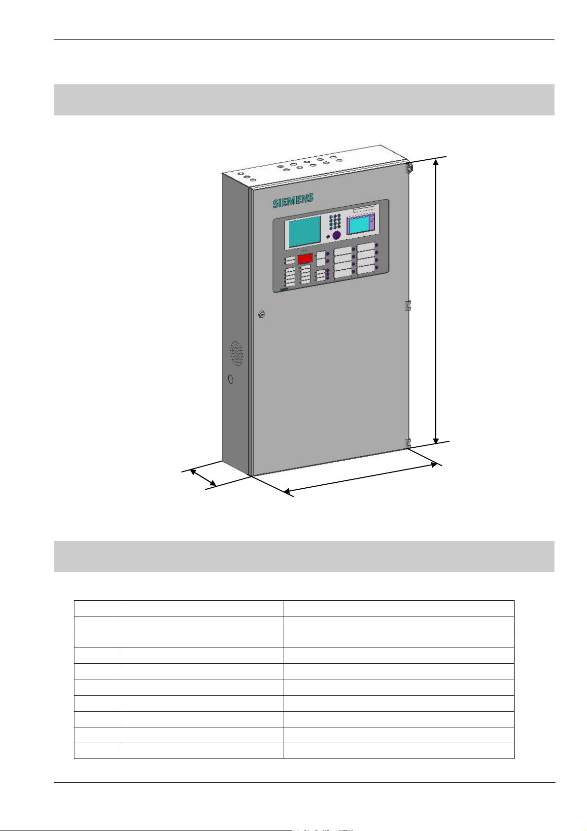
3. DIMENSIONS
1000
(In: mm)
Operating Manual of FC18 Controller
200 600
Fig. 1-1 Dimensions
4. COMPATIBLE EQUIPMENT LIST
Table 1-2
No. Type Description
1. FDT181 Heat detector
2. FDO181 Smoke detector
3. FDM181 Manual call point
4. FDCI181-2 Input module
5. FDCIO181-2 Input/output module
6. FT1810 Floor repeater display
7. FDCL181 Isolator
8. FT1811 Addressable Mimic Driver
9. FTM1811 Addressable Mimic Display Board
Page: 5/70

Operating Manual of FC18 Controller
5. SYSTEM STRUCTURE
- Up to 16 FC18 controllers can be networked together. Any controller can be set as master controller to supervise
devices connected with its slave controller and its own.
- Up to 20000 devices can be connected in one system.
Fig. 1-2 System structure
Page: 6/70
Operating Manual of FC18 Controller
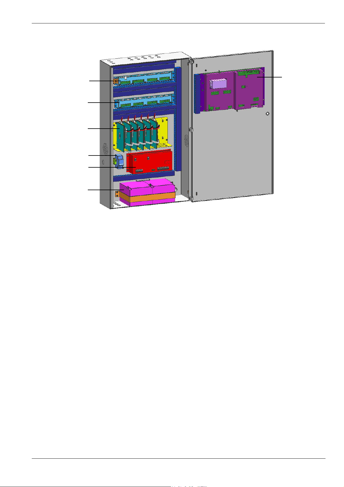
of main unit
Terminal Board
Terminal Board of
Line Card
Line Card & Plate
Breaker
Power Supply10A
Battery
Main Unit
Fig. 1-3 Internal structure
Page: 7/70
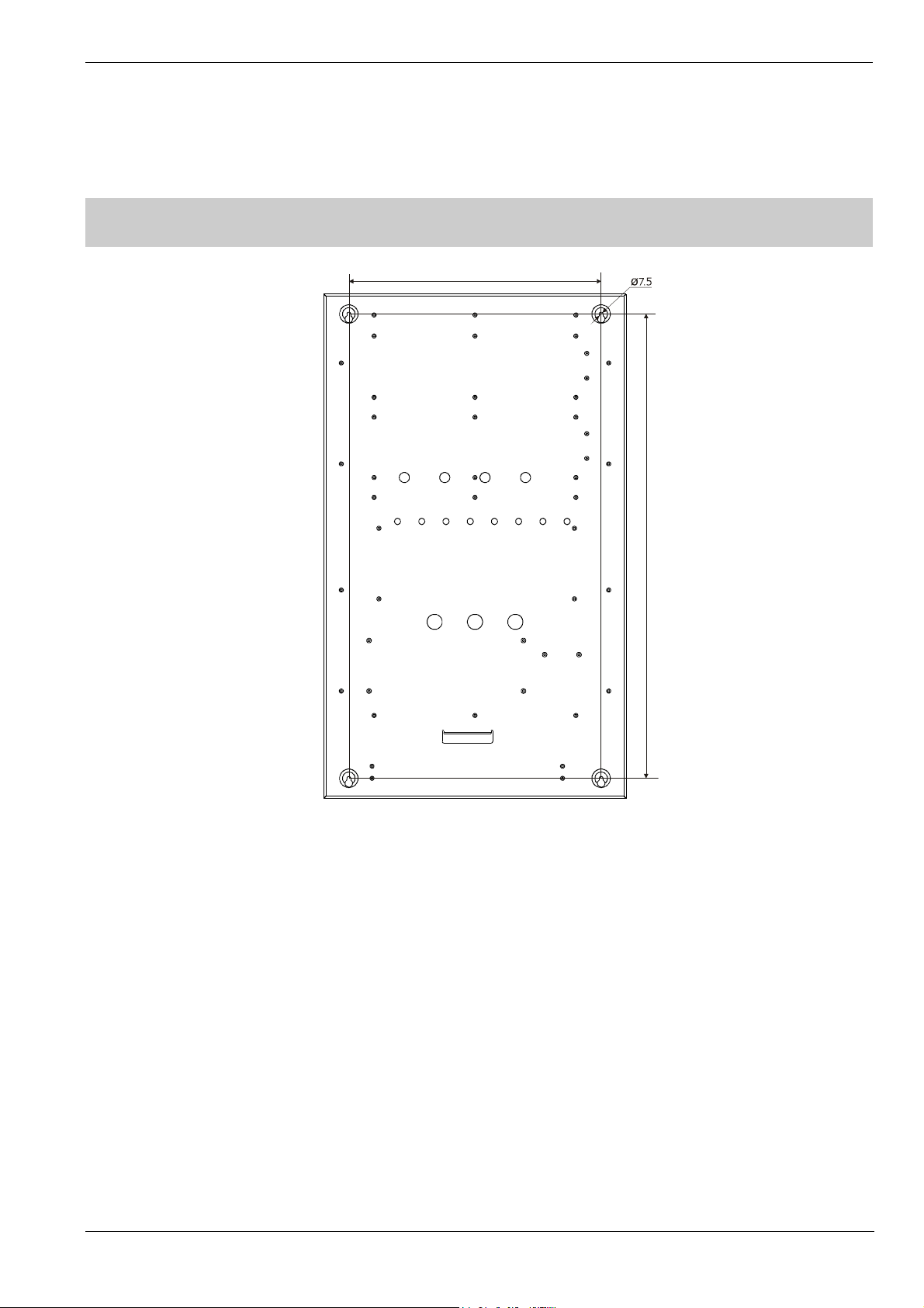
1. INSTALLATION
Operating Manual of FC18 Controller
CHAPTER 2 INSTALLATION
500
0
2
9
Fig. 2-1 Installation size (In: mm)
Note: Installation must comply with the local regulation!
Procedure:
1. Choose a place where is dry, clean, flat and firm for controller installation.
2. Choose a proper installation location to make sure the front door can be opened smoothly.
3. Mark 4 installation holes with pen on the wall for drilling. (Fig. 2-1)
4. Drill the holes, put expansion bolts in and insert the M6 screws.
5. Break the cable entries on the controller.
6. Hang the controller over those screws.
7. Insert cables into the controller.
8. Open the front panel and tighten the screws to fix the controller on the wall.
9. Connect cables to the terminals according to Fig. 2-2, 2-3, 2-4, 2-5, 2-6, 2-7, 2-8.
10. Install and secure the batteries properly.
11. Close the front panel. Lock it with special tools and store the tools in a safe place.
Page: 8/70

2. CONNECTION DIAGRAM
MB Link Ext. Pwr. Mntr. Pwr. Status Printer Pwr. MB Pwr.
Int.In
put 1-8
Operating Manual of FC18 Controller
CAN End
Printer
Int. Output 1-8
Table 2-1
DL RS485
Sign Description
MB Link Connect to “MB Link” port on terminal board of main unit
Ext. Reserved
Pwr. Mntr. Connect to “Pwr Monitor” port on terminal board of main unit
Pwr. Status Connect to “Signal monitor” port on power supply
Printer Pwr. Connect to printer
MB Pwr. Connect to “PS” port on main unit
CAN End Dip-switch, used to set EOL resistor of FC18-BUS/FR18-BUS
FCnet ID Dip-Switch, used to set FC18-BUS address no.
Reset Used to reset controller
CPU COM Connect to special converter module for download/upload software
LC-1/LC-2 Reserved
Int. COM Connect to port “RS485” on interlocking panel
LC COM Connect to line card
Printer COM Connect to printer
PS Connect to power supply and port “MB Pwr” on main unit
Int. ID Dip-Switch, used to set interlocking address no.
DL Used to download/upload interlocking software(internal use only)
RS485 Connect to port “Int.COM” on main unit
Int. Output 1-8 Connect to “Int. Output 1-8” port on terminal board of main board
Int. Input 1-8 Connect to “Int. Input 1-8” port on terminal board of main board
Printer Connect to printer
Int. ID
PS
图 2-2 Back side of Main Unit
Printer COM
LC-1 LC-2 Int. COM LC COM
FCnet ID
Reset
CPU COM
Page: 9/70
Operating Manual of FC18 Controller
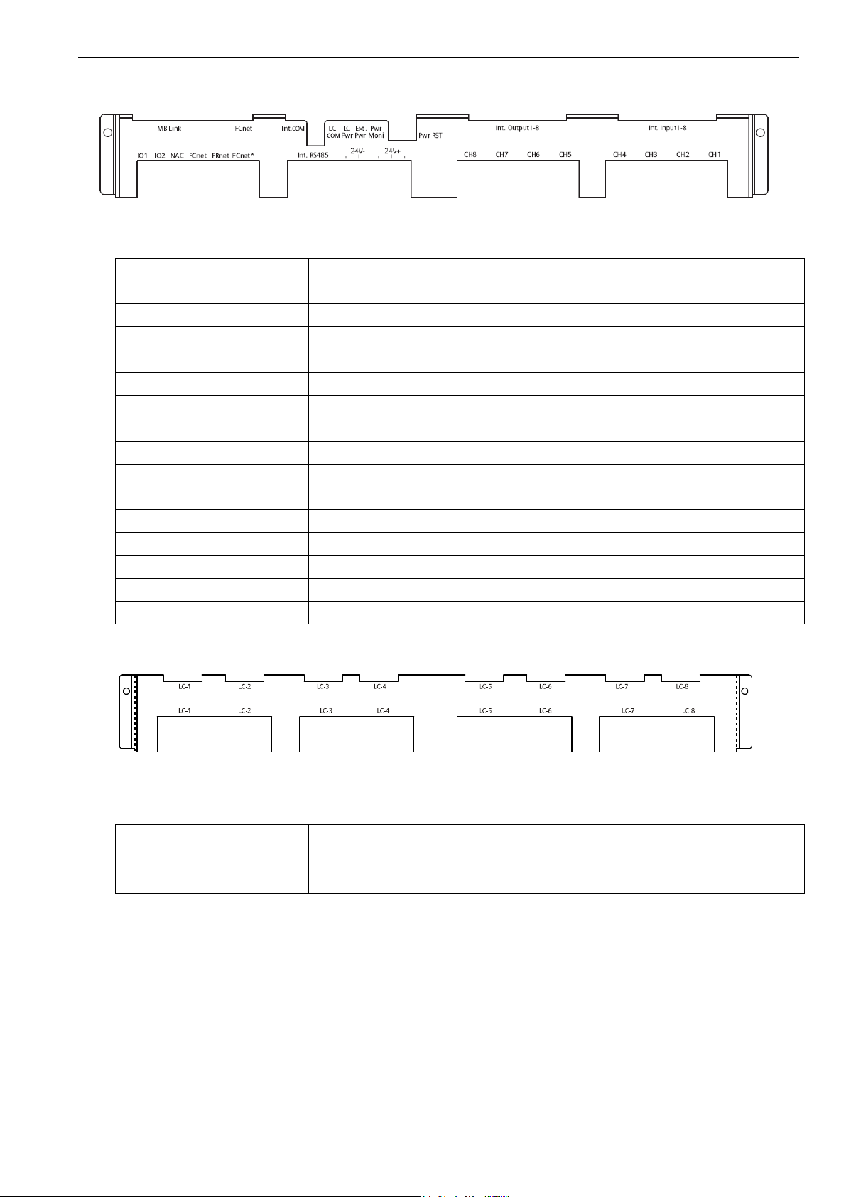
Fig. 2-3 Terminal board of main unit
Table-2-2
Sign Description
MB link /FCnet(upside)
Int. COM Reserved
LC COM Connect to line card for communication
LC Pwr Connect to line card for power supply
Ext. Pwr Connect to 24VDCpower supply
Pwr Moni Connect to port “PWR. MNTR” on main unit
Pwr RST Undefined
Int. Input /Int.Output Connect to the interlocking panel on main unit
IO1/IO2
NAC
FCnet
FRnet
Int.RS485 Reserved
24V-/24V+ Used for manufacture test (internal use only)
CH1-8
Connect to “MB Link” port on main unit
Programmable input\output(see to Fig.2-9)
Connect to NAC alarm(see to Fig.2-8)
Connect to controller(see to Fig.2-7)
Connect to floor repeater display FRT/Mimic driver(see Fig.2-6)
Connect to 8 channels of interlocking panel(see Fig.2-10)
Fig 2-4 Terminal board of line card
Table 2-3
Sign Description
LC-1/2/3/4/5/6/7/8(upside)
LC-1/2/3/4/5/6/7/8(underside) Connect to the field device(see Fig.2-5)
Connect to the line card
Page: 10/70
Operating Manual of FC18 Controller
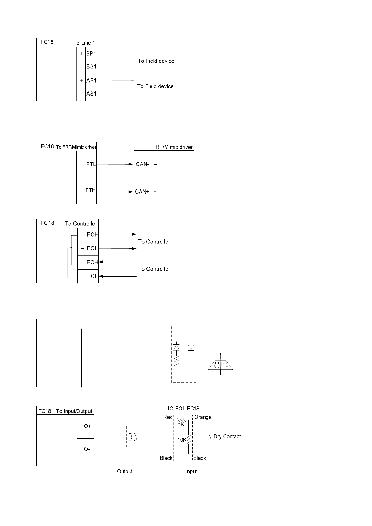
Note: In loop mode, wires from BP1 must end at AP1; wires from BS1 must end at AS1. The connection of field
devices (except FDCL181 isolator) is polarity free.
Fig. 2-5 Line card connection diagram (the same for other line)
Fig. 2-6 FRT/Mimic driver connection diagram
Note: Ensure positive and negative connections are properly in place, FC18-BUS is polarity sensitive.
Connect a 120Ω resistor as monitoring resistor. It must be connected to the end of the line. ( It also can be set
by the two-digit Dip-switch on the main board, see “Dip-switch” )
Fig. 2-7 Network connection diagram
FC18
To NAC
NAC-EOL-FC18
Red
NAC+
Orange
NAC-
Black
20K
resistor
Black
Visible and
audible device
Fig. 2-8 NAC connection diagram
Fig. 2-9 Main board input/output connection diagram
Page: 11/70
Operating Manual of FC18 Controller
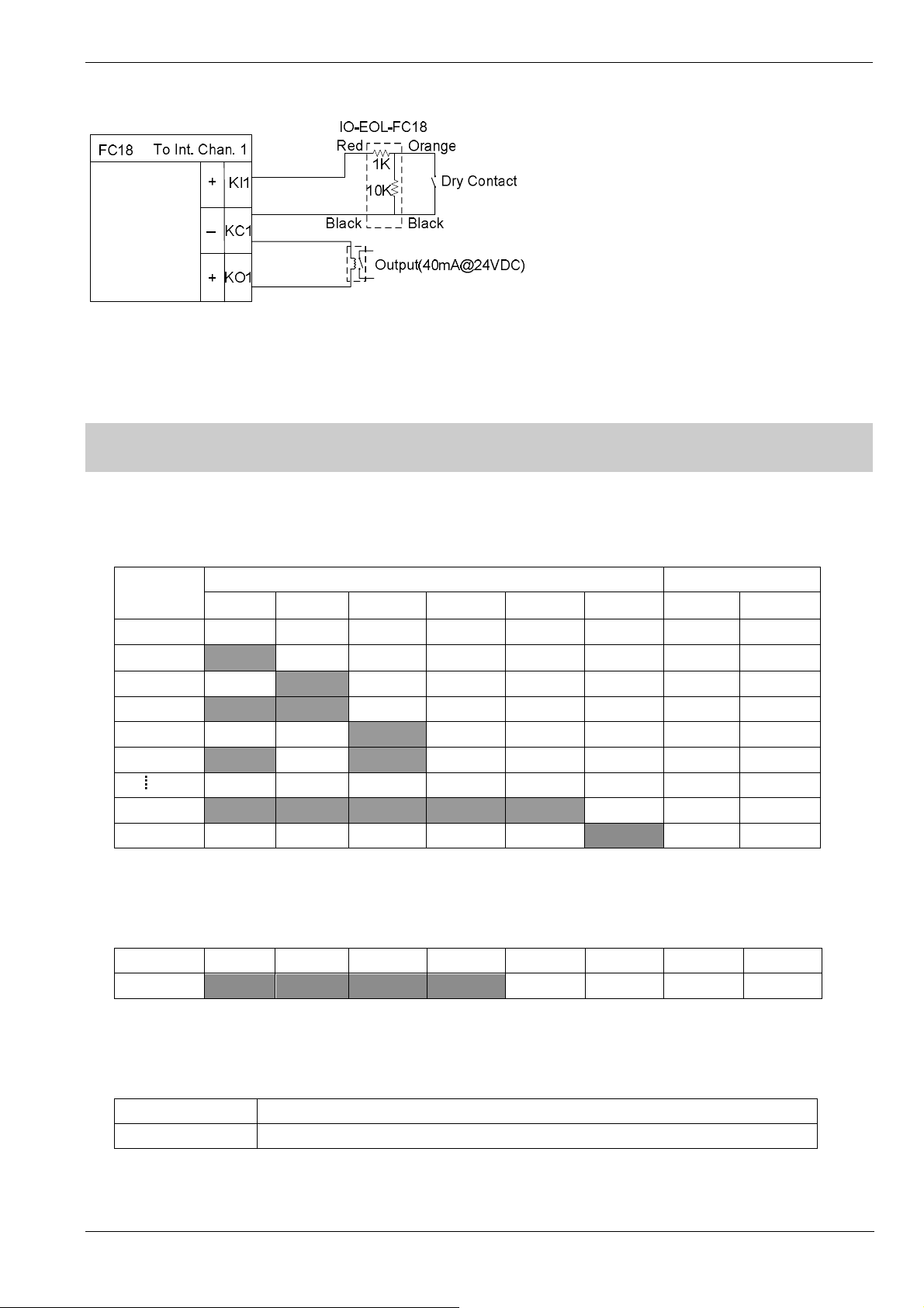
Fig. 2-10 Interlocking panel connection diagram (the same for other channels)
Note: the load range of each output is 24VDC, 600Ω – 1.2kΩ
3. DIP-SWITCH
There is a 8-digit Dip-switch FCnet ID (Fig. 2-2) on main unit. The 1-6 digit of Dip-switch is available, used to set 1-32
address of main unit. The 7-8 digit must be “Off”.
Table 2-4
FCnet
Address
Null Off Off Off Off Off Off Off Off
1
2 Off
3
4 Off Off
5
31
32 Off Off Off Off Off
There is a 8-digit Dip-switch Int. ID (Fig. 2-2) on interlocking panel .The 1-4 digit of Dip-switch is available, used to set
address of interlocking panel. The address No. is fixed as 15. The 5-8 digit is “Off”.
Table 2-5
Address D1 D2 D3 D4 D5 D6 D7 D8
15
1 2 3 4 5 6 7 8
On
On On
On
On On On On On
On On On On
Off Off Off Off Off Off Off
On
Off
Dip-Switch Reserved
Off Off Off Off Off Off
Off Off Off Off Off Off
On
On
Off Off Off Off Off
Off Off Off Off Off
Off Off Off
On
Off Off Off Off
Off Off
There is a 2-digit Dip-switch CAN End (Fig. 2-2) on main unit. It is used to set 120Ω EOL resistor of FC18-BUS and
FR18-BUS.
Table 2-6
1
2
On:FC18-BUS EOL is connected; Off:not connected
On:FR18-BUS EOL is connected; Off:not connected
Page: 12/70

4. POWER SUPPLY
input
- Stable and reliable DC output
- Auto switch between main power and battery
- Alternative AC power switch
- Charge and protect battery
- Monitor main power, battery, trouble status
- Auto recoverable current protection circuit for overload and short circuit
Operating Manual of FC18 Controller
Switch between 220VAC
and 110VAC
Connect external AC
Connect to port “Pwr
Status” on main unit
Fig. 2-11 AC input switch
Connect to battery
Connect to port” PS” on
main unit and line card
Fig. 2-12 Wire connection
Page: 13/70

Operating Manual of FC18 Controller
Table 2-7 Specification of power supply
Input voltage 110/220 VAC
Input frequency 60/50 Hz
Output voltage 24 VDC
Output current 10A
AC fuse capacity 110VAC: 6A 220VAC:3A
DC fuse capacity 10A
Operating temperature
Storage temperature
Humidity
Size 326*130*88 mm
0 ~ +40℃
when it is over 40℃, output power will reduce half
-20 ~ +60℃
≤95% (40±2℃)
Page: 14/70

1. INTERFACE
Operating Manual of FC18 Controller
CHAPTER 3 OPERATION
3
1
2
4
LCD
①
The LCD backlight automatically turns off within the preset time in the idle mode; the preset time can be adjusted in
the parameter setting. Press any key turns on the LCD again.
Printer
②
There are two indicators and two keys on the printer panel. Indicator: the green LED indicates power status while the
red LED indicates working status (on: online; off: offline). Key: SEL (set online/offline), LF (paper feed).
Key board
③
¹ Press number keys to enter numbers and letters.
¹ C: Press “C” to cancel or return to the previous menu; Press “OK” to confirm or enter the menu.
¹ : Menu button, press it to display menu.
¹ Press “↓”/”↑” to move the cursor.
¹ Press “←” to delete the previous input.
¹ Press “→“as shortcut key to show the function menu. The operation items of the selected device are listed in the
menu according to operator’s user level.
Indicators and operation keys
④
¹ Alarm: Off when there is no fire; on when fire is detected; off again when all alarms are cleared and "reset" is
pressed.
5
Fig. 3-1 Operation panel
Page: 15/70

Operating Manual of FC18 Controller
¹ Supervision: On when supervision signal is detected; off when the signal disappears and “reset” is pressed.
¹ System trouble: On when system hardware/software is faulty.
¹ Trouble: On when trouble happen; off when trouble is resolved.
¹ Activation: On when output device (such as output module or main board output port) is activated; Off when
activation signal disappears and “reset” is pressed.
¹ Confirmation: On when controller receives confirmation signal; off when the signal disappears.
¹ NAC trouble: On when a trouble happens on NAC line; off when trouble disappears.
¹ Main Power: On when main power supply is working; off when the AC supply is disconnected.
¹ Battery: On when backup batteries are working; off when the Main power are working and the backup batteries
are not working.
¹ Disable: On when some equipment is disable; off when no equipment is disable; Flashing when system is at
startup status.
¹ Test: On when some device is at test/walk-test mode; off when no device is being tested.
¹ NAC disable: On when NAC line is disable; off when it’s enable.
¹ Auto: Only level 2&3 users can access. At auto mode all interlocking equipment can be activated automatically
by controller according to pre-defined interlocking expression. Manual operations have high priority at
auto mode.
¹ Manual: Level 2&3 user can access. At manual mode all interlocking equipment only can be activated manually.
¹ Acknowledge/Silence: Only level 2&3 users can access. Press “Acknowledge/Silence” to turn off the buzzer
(except when battery is under voltage).
- Flashing when there are events and “Acknowledge/Silence” is not pressed. OR when there are
events and “Acknowledge/Silence” is pressed while new event occurs.
- Off when there are events and “Acknowledge/Silence” is pressed. OR when there are no events.
Sound elimination in a network,
- Press “Acknowledge/Silence” on master controller: internal sounder will turn off for both master and
slaves, also indicator will turn off.
- Press “Acknowledge/Silence” on slave controller: internal sounder will turn off slave itself, also
indicator will turn off, but master remains unaffected.
¹ NAC activation: Only level 2&3 users can access. When fire is detected, NAC is activated and the LED is on.
Press “NAC activation” to deactivate NAC devices and the LED is off. Press it again, NAC device is
activated again and the LED is on. So on and so forth.
- “NAC activation” button is used to activate/deactivate NAC devices.
- NAC device can be disabling through the menu.
- NAC device cannot be activated neither the alarm nor pressing key when NAC device is disable.
- When NAC device is activated, it can be disable. But when it is enable again, its status will be normal
(no matter there is fire alarm or not).
- The LED is used to show NAC device status. The LED is on when NAC device is activated and off
when NAC device is deactivated.
¹ Reset: Only level 2&3 users can access. It is used to reset system. Any event can be reset by pressing this key
no matter it’s acknowledged or not. But to reset fire alarm event is different from to reset non-fire alarm
events in a network.
- Non-fire alarm events:
If master is reset, events in both master and salves are reset.
If a slave is reset, events in the slave are reset; the same events in master are also reset.
- Fire alarm event:
If master is reset, events in both master and salves are reset.
If a slave is reset, events in the slave are reset while the same events in master will not reset
Page: 16/70

Interlocking panel
⑤
The interlocking panel has 8 output channels. Each channel has indicators to indicate trouble, activation and
confirmation status. Each channel can be controlled by Activation/Deactivation button manually. Only level 2&3 user
can access. Press the button to activate it and press it again to deactivate it, so on and so forth.
¹ Trouble: On when there's trouble; off when trouble is solved.
¹ Activation: On when output channel is activated; flashing when there's no confirmation; Off when the output
¹ Confirmation: On when confirmation is received; off when confirmation signal disappears.
Operating Manual of FC18 Controller
until master is reset.
channel resume normal.
Page: 17/70
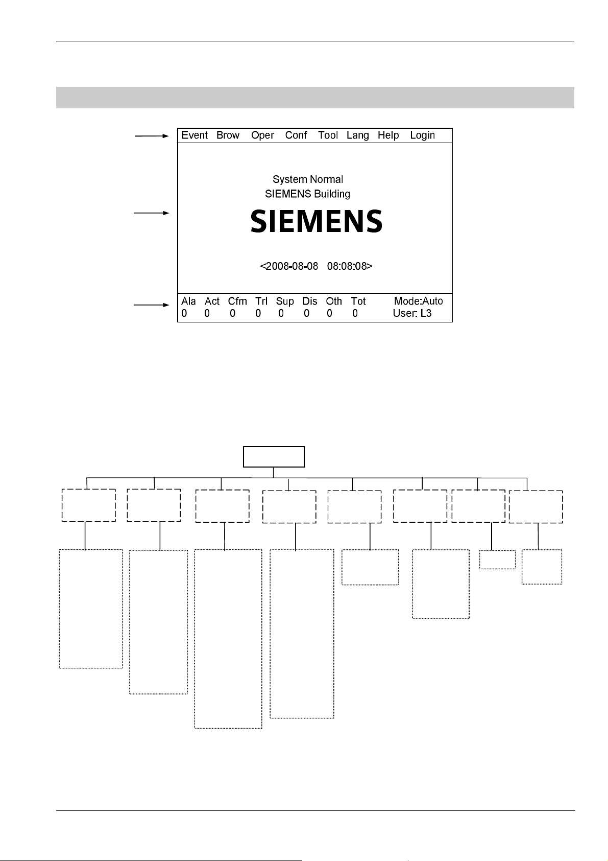
2. LCD WINDOW
③①②
—About
—Logout
system
Operating Manual of FC18 Controller
Fig. 3-2 Display screen
FC18 controller has 3 windows which are menu window (1), browser window (2) and statistics window (3).
① Menu window:
¹ Display operation menus according to different user levels. Items for Level 3 are shown as follows.
Main menu
—Alarm & active
—Trouble
—Supervision
—Disable
—Test
—Walk-test
—Locate
BrowseEvent
—All
—Unconfigure
—Unknown
—Inconsistent
—Exchange
—History
—Property
—Others
Operate
—Disable
—Enable
—Open
—Close
—Activate
—Deactivate
—Test
—Walk-test
—Restore
—Locate
—Stop locating
Configure Login
—Edit parameter
—Save configure
—Assign group
—Assign FRT
—Equipment
replacement
—Create logic.
—View logic
—Edit logic
—Delete logic
Tool
—Set time
—Check
Lang
—English
—Taiwan
—Hong Kong
—Portugal
Help
—Login
Page: 18/70

Operating Manual of FC18 Controller
② Browser window:
¹ Display real-time events: fire alarm, activation & confirmation, trouble, supervision, disable, test and walk-test.
¹ Display node tree.
¹ Priority of display: fire alarm→ activation & confirmation→ supervision→ disable→ trouble→ test/walk-test→ normal.
③ Statistics window:
¹ Display total number of real-time events including fire alarm, activation, confirmation, trouble, supervision and disable.
¹ Display current user level and controller mode.
¹ icon is displayed when system clock is wrong, possible reason is : the button battery on main board is used or
clock chip cannot work normally.
Page: 19/70

Operating Manual of FC18 Controller
3. USER LEVEL
l FC18 has 3 user levels. User level is displayed at the lower right corner of the screen (Fig. 3-2)
l Users of different levels have their own operation interfaces.
Table 3-1 user level list
Item Level 1 Level 2 Level 3
Login √
Logout √ √
Real-time event query √ √ √
History query √ √ √
Property query √ √ √
Disable/Enable devices √ √
Activation/Deactivation devices √ √
Test √ √
Walk-test √ √
Restore √ √
Locate √ √
Stop locating √ √
Login time setting √
Buzzer level setting √
LCD closing time setting √
System time setting √
Auto/manual mode setting √ √
Edit parameter √
Create logic expression √
Delete logic expression √
Edit logic expression √
View logic expression √
Print events √ √ √
Save configure √
Operate interlocking panel √ √
System check √
Acknowledge/Silence √ √
NAC activation/deactivation √ √
Group assignment √
FRT assignment √
Change language √
Reset √ √
Page: 20/70
 Loading...