

Page 1
Building Technologies
Fire Safety & Security Products
FC18 Controller
Operating manual
Page 2

Operating Manual of FC18 Controller
Page: 1/63
TABLE OF CONTENTS
CHAPTER 1 SYSTEM OVERVIEW ················································································································ 3
1. FEATURES ······································································································································· 3
2. TECHNICAL DATA ····························································································································· 4
3. DIMENSIONS···································································································································· 5
4. COMPATIBLE EQUIPMENT LIST ··········································································································· 5
5. SYSTEM STRUCTURE ······················································································································· 6
CHAPTER 2 INSTALLATION ······················································································································· 8
1. INSTALLATION ·································································································································· 8
2. CONNECTION DIAGRAM ···················································································································· 9
3. DIP-SWITCH ··································································································································· 10
4. Power Supply ··································································································································· 11
CHAPTER 3 OPERATION ·························································································································· 13
1. INTERFACE ···································································································································· 13
2. LCD WINDOW································································································································· 16
3. USER LEVEL ·································································································································· 18
4.1 Login ········································································································································· 19
4.2 Logout ········································································································································ 19
5. STATUS TYPES ······························································································································· 20
6. FIRE ALARM EVENT HANDLING········································································································· 22
7. TROUBLE EVENT HANDLING ············································································································ 23
8. SUPERVISION EVENT HANDLING ······································································································ 24
9. ACTIVATION/CONFIRMATION EVENT HANDLING ·················································································· 25
10. REAL-TIME QUERY ························································································································· 26
11. HOW TO QUERY EQUIPMENT PROPERTY··························································································· 27
12. HOW TO QUERY HISTORY················································································································ 28
13. HOW TO DISABLE/ENABLE ··············································································································· 29
14. HOW TO ACTIVATE/DEACTIVATE THE CONTROLLER ············································································ 30
15. HOW TO TEST/WALK-TEST ··············································································································· 31
16. HOW TO LOCATE/STOP LOCATING ···································································································· 32
17. HOW TO ADJUST BUZZER LEVEL ······································································································ 33
18. HOW TO SET LOGIN TIME ················································································································ 34
19. HOW TO SET WALK-TEST TIME ········································································································· 35
20. HOW TO SET LCD CLOSING TIME ······································································································ 36
21. HOW TO SET TIME ·························································································································· 37
22. HOW TO CHECK SYSTEM ················································································································ 38
23. HOW TO SAVE CONFIGURE ·············································································································· 39
24. HOW TO EDIT PARAMETER ·············································································································· 40
25. HOW TO CREATE/VIEW LOGIC ·········································································································· 41
26. HOW TO EDIT/DELETE LOGIC ··········································································································· 42
27. HOW TO ASSIGN GROUP/ FRT ·········································································································· 43
28. HOW TO GET HELP ························································································································· 44
29. HOW TO OPERATE INTERLOCKING PANEL ························································································· 45
30. HOW TO OPEN/CLOSE A PRINTER ····································································································· 46
Page 3

Operating Manual of FC18 Controller
Page: 2/63
31. HOW TO REPLACE DEVICE ·············································································································· 48
32. HOW TO UPGRADE TO FC1840 ········································································································· 49
33. HOW TO CHANGE LANGUAGE ·········································································································· 50
34. HOW TO QUERY THE INFORMATION OF OTHER EVENTS ······································································ 51
CHAPTER 4 MAINTENANCE ······················································································································ 52
1. DAILY EXAMINATION ······················································································································· 52
2. EMERGENCY AND TROUBLE HANDLING ···························································································· 52
APPEN DIX 1 P A RA METE R LIST ··················································································································· 54
APPEN DIX 2 OPERABLE ITE M LIST ·············································································································· 57
APPEN DIX 3 EQUIP MENT GROUP ING T ABLE ································································································· 59
APPEN D IX 4 RULE S F OR LOGIC EXPR ES SION ······························································································ 60
APPEN DIX 5 INPU T METH OD ······················································································································ 62
APPENDIX 6 “STICKER METHOD”EASY FOR COM MISS IONIN G ····································································· 63
Page 4

Operating Manual of FC18 Controller
Page: 3/63
CHAPTER 1 SYSTEM OVERVIEW
There are three types of FC18 series controllers:
- FC1820 fire alarm controller (interlocking)
- FC1840 fire alarm controller (interlocking)
- FC1840C fire alarm controller (no interlocking panel, no printer)
1. FEATURES
- Fulfill Chinese Standard of GB4717-2005 and GB16806-2006.
- Multi-language operation menu designed with windows style for fast and easy operation.
- Shortcut key (right key) for popping out operation items of equipment/event.
- Large memory space for up to 10000 history records, first in first out order, all events can be recorded
during operation period.
- LCD backlight Auto-off mode. When no operation or event to display within preset time, LCD backlight
will be automatically turn off. When there are events / operations, LCD will light up automatically to
display events and/or interlocking devices.
- 2 channels of programmable input/output (Output: 40mA@24VDC, it can be programmed as general
alarm output or general trouble output; Input: dry contact).
- 1 channel of NAC for audible and visible devices (max. 0.5A @24VDC).
- 8 channels of interlocking functions for automatic control and manual operations of control equipments.
- Efficient group programming according to different using.
- FC1820 controller can connect up to 252 points, FC1840(C) controller can connect up to 504 points.
- Network bus (FC18-BUS), the max. distance is 1000m (the twist wiring capacity is 1.0 to 1.5 mm
2
). Up to
32 controllers can be networked together with FC1820 and FC1840(C).
- FRT bus (FR18-BUS), the max. distance is 1000m (the twist wiring capacity is 1.0 to 1.5 mm
2
). Up to 32
floor repeater displays can be networked.
- Detection bus (FD18-BUS), 2-wire polarity-free, the max. distance for line resistance is 4000m, the max.
distance for line capacitance is 5000m. (the twist wiring capacity is 1.0 to 1.5 mm2)
- Three user levels for different operation authority. Each user level is accessed by a pre-defined and
changeable password.
- Convenient pluggable terminals with clear marks for field wiring.
- Auto-mapping function to support on commissioning task.
- Detection algorithm can be adjusted from controller according to different environment, to provide high
reliability of alarm and reduce false alarm.
- Programming can be done either directly on controller or through computer.
- “Sticker Method” easy for commissioning on site.
Page 5

Operating Manual of FC18 Controller
Page: 4/63
2. TECHNICAL DATA
Item Parameter
FC1820 FC1840 FC1840C
No. of line modules 1 2 2
No. of points 252 504 504
LCD screen
320×240 pixels,backlit
No. of programmable input/output on mainboard 2
No. of zone of interlocking panel 8 0
No. of NAC (0.5mA @24VDC) 1
Max. history records 10000
Max. distance between controllers within FC18-BUS 1,000 m
Max. No. of controllers connected within FC18-BUS 32
Max. distance between a controller and a FRT within FR18-BUS 1,000 m
Max. No of FRT connected to a controller 32
Auto-mapping function Operation from terminal
Battery(not included) Depends on local regulation
Communication interface Special converter module
Input voltage 220 V@1.5 A, 110V@3 A
220 V / 50 Hz, 110V / 60 Hz
Power supply capacity 5 A@24 VDC
External power output 1 A@24 VDC
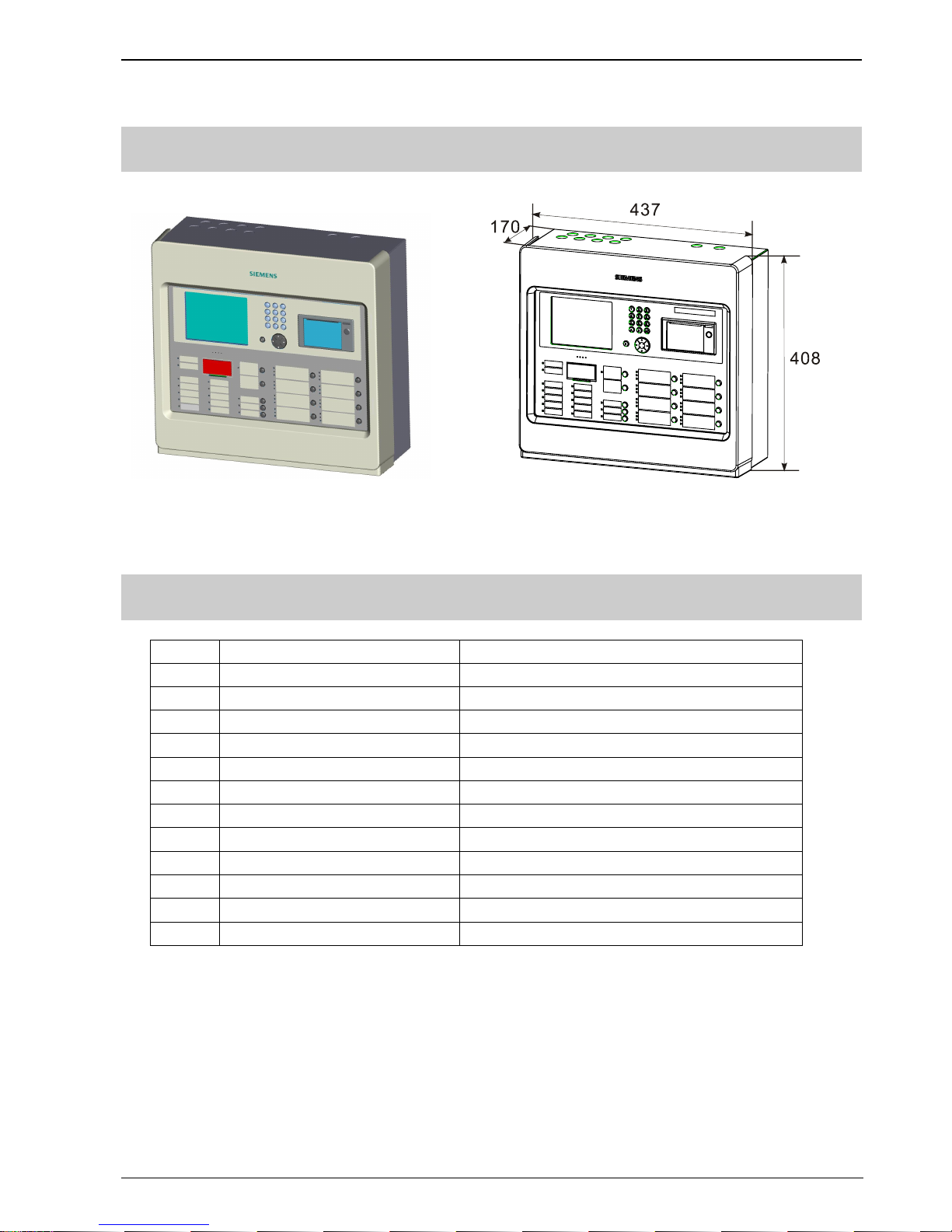
Size (mm) 437×408×197
Weight (without battery) 10.35 Kg
Power fuse 1.5 A
Battery fuse 5.0 A
Operating temperature
0 ~ +40 ℃
Storage temperature
–10 ~ +50 ℃
Relative humidity
≤95%(40±2 ℃)
Protection category IP30
Environment requirement Indoor / Clean
Page 6
Operating Manual of FC18 Controller
Page: 5/63
3. DIMENSIONS
Fig. 1-1 FC18 Appearance Fig. 1-2 FC18 Dimensions (mm)
4. COMPATIBLE LIST
No. Type Description
1. FDT181 Addressable heat detector
2. FDO181 Addressable smoke detector
3. FDM181 Addressable manual call point
4. FDCI181-2 Addressable input module
5. FDCIO181-2 Addressable input/output module
6. FDCI181-1 Addressable input module
7. FDCIO181-1 Addressable input/output module
8. FT1810 Addressable floor repeater display
9. FDCL181 Isolator
10. FT1811 Addressable mimic drive
11. FTM1811 Addressable mimic display board
12. FDCAI181 Addressable alarm indicator
Page 7
Operating Manual of FC18 Controller
Page: 6/63
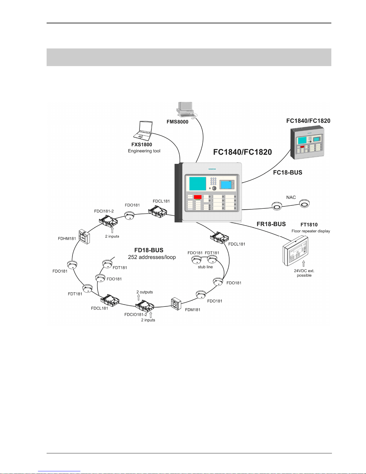
5. SYSTEM STRUCTURE
- Up to 32 FC1820/40(C) controllers can be networked together. Any controller can be set as master
controller to supervise devices connected with its slave controller and its own.
Fig. 1-3 System structure
Page 8

Operating Manual of FC18 Controller
Page: 7/63
Fig. 1-4 Internal structure
Po
wer supply
Terminal board
B
attery
Line card 2
Line card 1
LED screen
Keyboard 2
Interlocking panel
Pinter
Keyboard 1
Main board
CPU board
Page 9
Operating Manual of FC18 Controller
Page: 8/63
CHAPTER 2 INSTALLATION
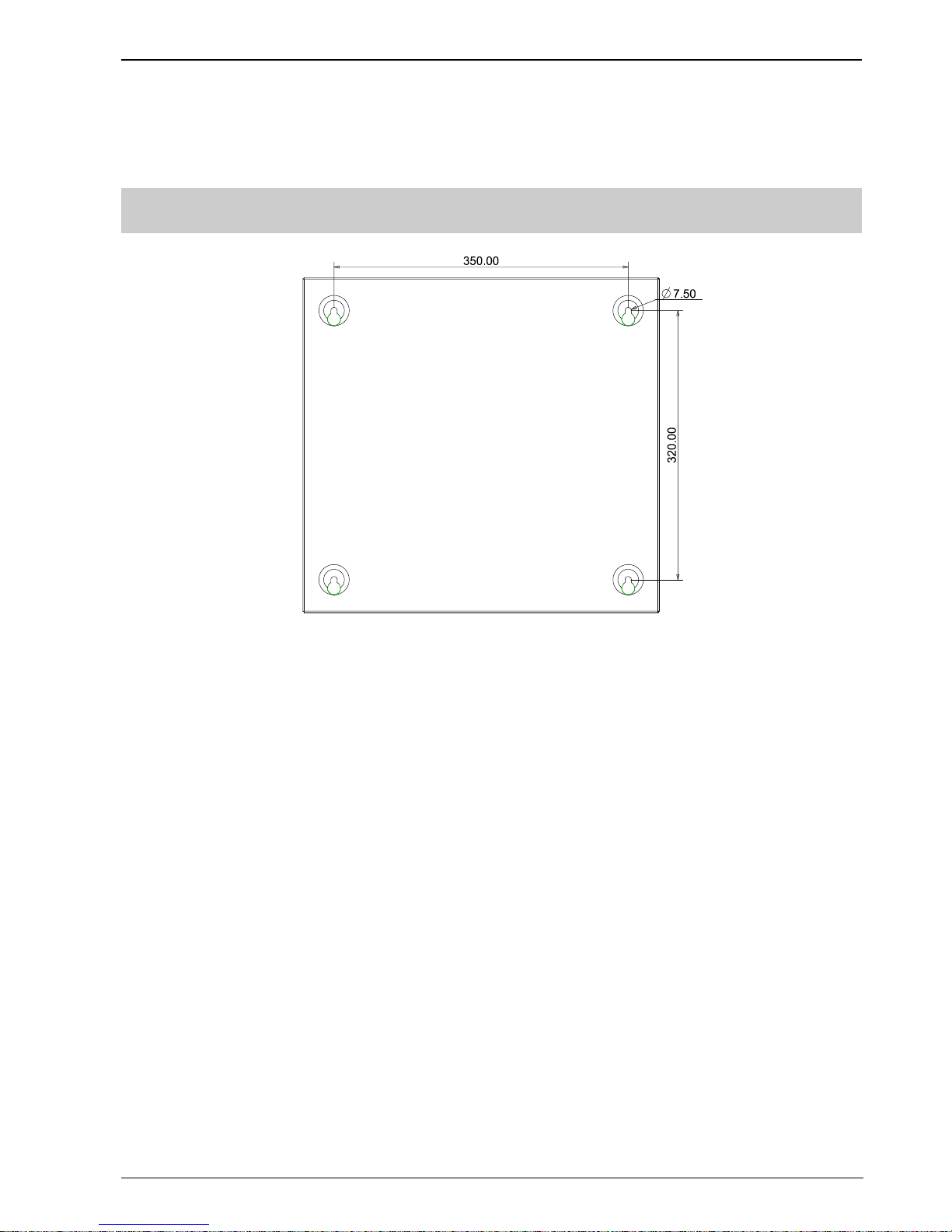
1. INSTALLATION
Fig. 2-1 Dimensions (mm)
Installation must comply with the local regulation!
1. Ensure the wall is dry, clean, flat and firm in which the controller is installed.
2. Chose a proper installation location to make sure the front door can be opened smoothly.
3. Mark the drillings for 4 installation holes on the wall. (Fig. 2-1)
4. Drill the holes, put expansion bolts in and insert the M6 screws.
5. Break the cable entries on the controller.
6. Hang the controller over those screws.
7. Insert cables into the controller.
8. Open the front panel and tighten the screws to fix the controller on the wall.
9. Connect cables to the terminals according to Fig. 2-2, 2-3, 2-4, 2-5, 2-6, 2-7, 2-8.
10. Install and secure the batteries properly.
11. Close the front panel. Lock it with special tools and store the tools in safe place.
Page 10
Operating Manual of FC18 Controller
Page: 9/63
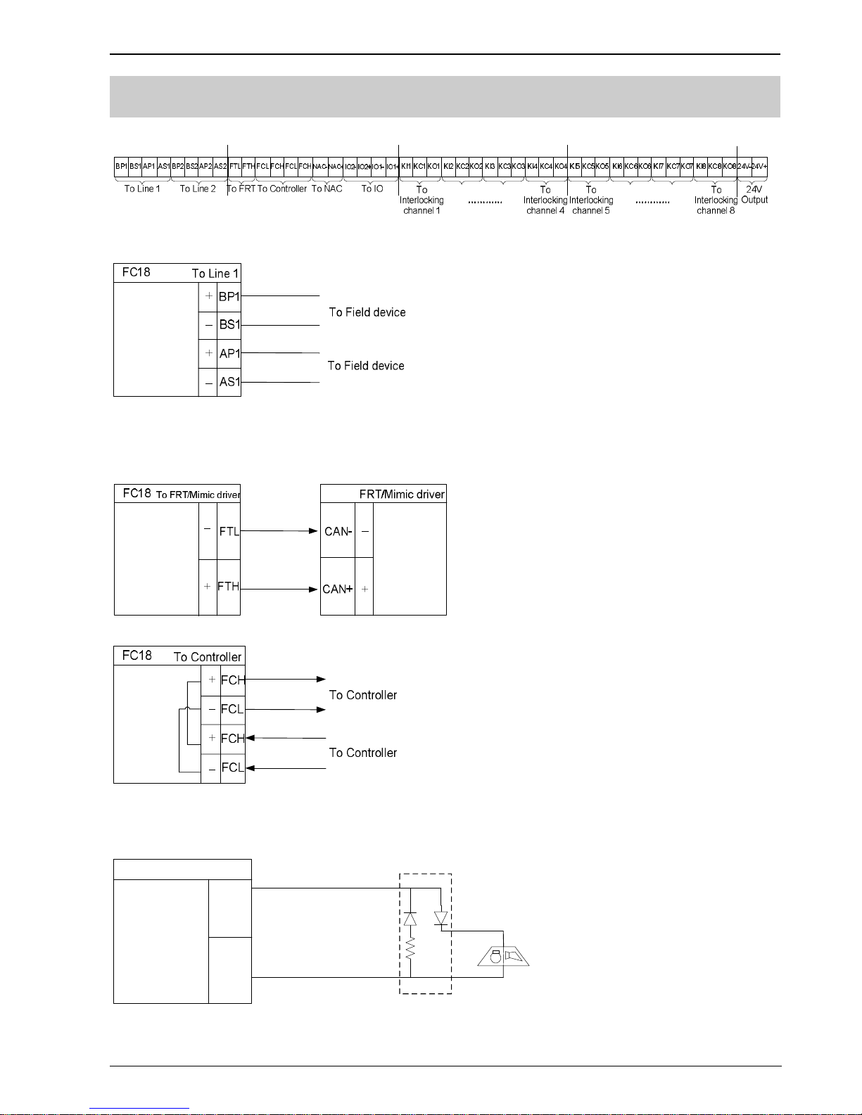
2. CONNECTION DIAGRAM
Fig. 2-2 Terminal line
Note: In loop mode, wires from BP1 must end at AP1; wires from BS1 must end at AS1. The connection of field
devices (except FDCL181 isolator) is polarity free.
Fig. 2-3 Line card connection diagram (the same for Line 2)
Fig. 2-4 FRT/Mimic driver connection diagram
Note: Ensure positive and negative connections are properly in place; FC18-BUS is polarity sensitive.
Connect a 120Ω resistor as monitoring resistor. It must be connected to the end of the line. ( It can be set by
the two-digit Dip-switch on the main board, see “Dip-switch connection configuration” )
Fig. 2-5 Network connection diagram
Visible and
audible device
FC18
To NAC
NAC+
NAC-
Red
Black
Orange
Black
20K
resistor
NAC-EOL-FC18
Fig. 2-6 NAC connection diagram
Page 11
Operating Manual of FC18 Controller
Page: 10/63
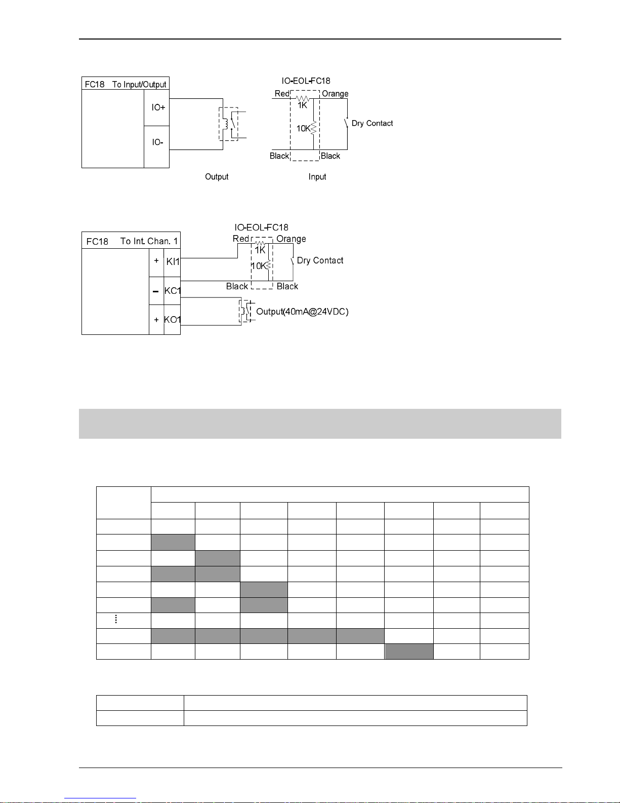
Fig. 2-7 Main board input/output connection diagram
Fig. 2-8 Interlocking panel connection diagram (the same for other channels)
Note: the load range of each output is 24VDC, 600Ω – 1.2kΩ
3. DIP-SWITCH
Each controller/interlocking panel has an eight-digit Dip-switch for address setting. Each Dip-switch can set address
1-32 within its first 6 digits.
FC18-BUS
address
DIP switches
1 2 3 4 5 6 7 8
Idle Off Off Off Off Off Off Off Off
1
On
Off Off Off Off Off Off Off
2 Off
On
Off Off Off Off Off Off
3
On On
Off Off Off Off Off Off
4 Off Off
On
Off Off Off Off Off
5
On
Off
On
Off Off Off Off Off
31
On On On On On
Off Off Off
32 Off Off Off Off Off
On
Off Off
The controller has a two-digit Dip-switch for setting terminal resistor of FC18-BUS or FR18-BUS.
1
On:FC18-BUS terminal selected; Off:not selected
2
On:FR18-BUS terminal selected; Off:not selected
Page 12

Operating Manual of FC18 Controller
Page: 11/63
4. Power Supply
- Stable and reliable DC output
- Auto switch between main power and battery
- Alternative AC power switch
- Charge and protect battery
- Monitor main power, battery, trouble status
- Auto recoverable current protection circuit for overload and short circuit
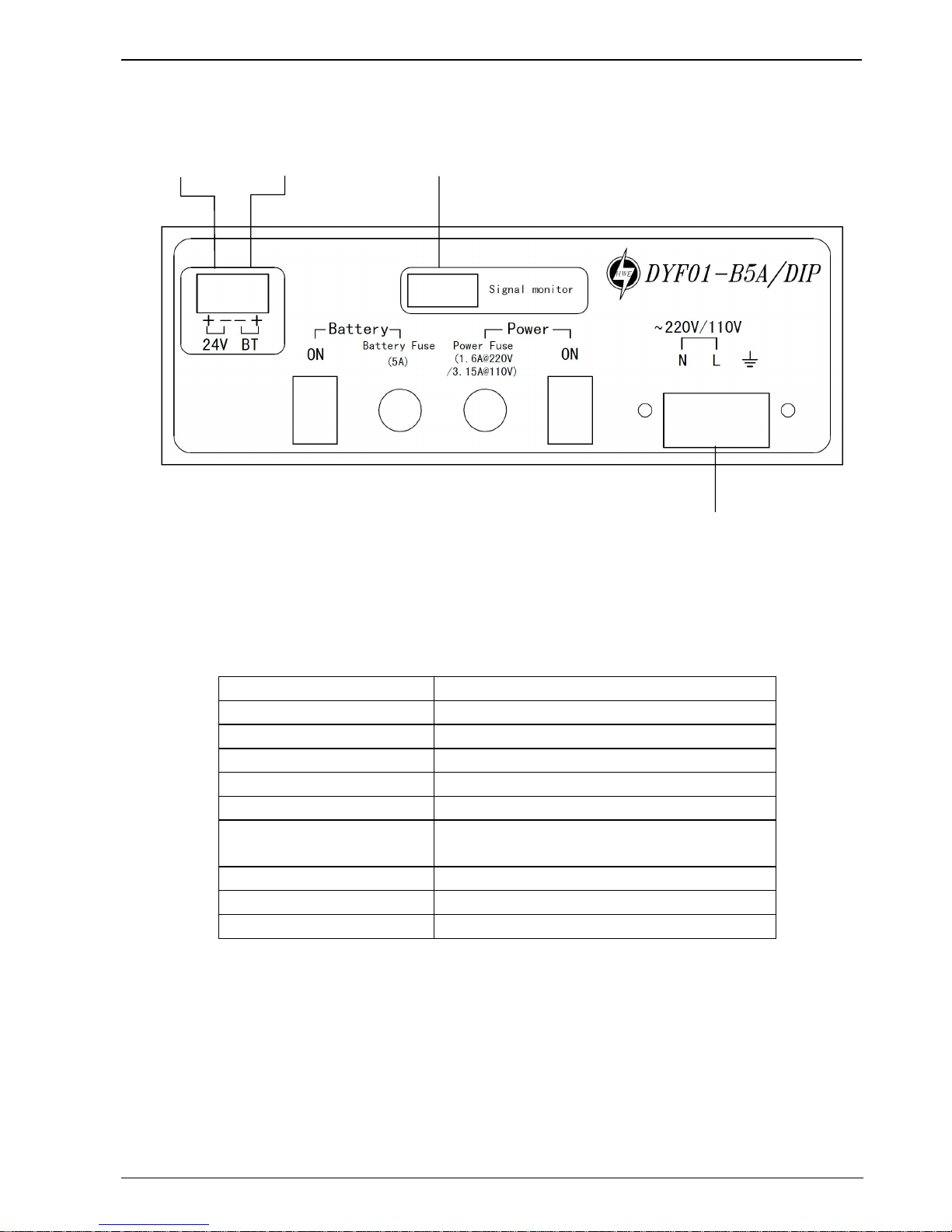
Fig. 2-9 AC Input Switch
Switch between 220VAC
and 110VAC
Page 13
Operating Manual of FC18 Controller
Page: 12/63
Fig. 2-10 Wire connection
Specification of power supply
Input voltage 110/220 VAC
Input frequency 60/50 Hz
Output voltage 24 VDC
Output current 5A
AC fuse capacity 110VAC: 3.15A 220VAC:1.6A
DC fuse capacity 5A
Operating temperature 0 ~ +40℃
when it is over 40℃, output power will reduce half
Storage temperature -20 ~ +60℃
Humidity ≤95% (40±2℃)
Size 220*136*70 mm
Connect external AC input
Connect to
battery
Connect to port
” PS” on main unit
Connect to port “Pwr
Status” on main unit
Page 14

Operating Manual of FC18 Controller
Page: 13/63
CHAPTER 3 OPERATION
1. INTERFACE
Fig. 3-1 Operation panel
① LCD
The LCD backlight automatically turns off within the preset time in the idle mode; the preset time can be adjusted in
the parameter setting. Press any key will turn on the LCD again.
② Printer
There are two indicators and two buttons on the printer panel. Indicator: the green LED indicates power-up state while
the red LED for operation state (on: online; off: offline). Button: SEL (set online/offline), LF (line feed).
③ Key board
¹ Press number keys to enter numbers and characters.
¹ C: Press “C” to cancel or return to the previous menu; Press “OK” to confirm or enter the menu.
¹ : Menu button, press “ ” to show menu.
¹ Press “↓”/“↑” to move the cursor.
¹ Press “←” to delete the previous input.
¹ Press “→” as shortcut key to show the function menu. The operation items of the selected equipment are listed
in the menu according to operator’s user level.
④ Indicators and operation keys
¹ Alarm: Off when there is no fire; On when fire detected; Off again when all alarms are cleared and "reset" is
pressed.
¹ Supervision: On when supervision signal is detected; Off when the event disappears and “reset” is pressed.
Page 15

Operating Manual of FC18 Controller
Page: 14/63
¹ System trouble: On when system hardware/software is faulty.
¹ Trouble: On when trouble occurs; Off when trouble is resolved.
¹ Activation: On when some equipment (such as output module or main board output port) is activated; Off when
activation signal disappears and “reset” is pressed.
¹ Confirmation: On when controller receives confirmation signal; Off when the signal disappears.
¹ NAC trouble: On when trouble occurs on NAC line; Off when trouble disappears.
¹ Main Power: On when main power supply is working; Off when the AC supply is disconnected.
¹ Battery: On when backup batteries are working; Off when the Main power are working and the backup batteries
are not working.
¹ Disable: On when some equipment is disable; Off when no equipment is disable; Flashing when system is in
startup status.
¹ Test: On when some equipment is at test/walk-test mode; Off when no equipment is being tested.
¹ NAC disable: On when NAC line is disable; Off when it’s enable.
¹ Auto: Only level 2&3 users can access. At auto mode all interlocking equipments can be activated automatically
by controller according to interlocking expressions. Manual operations have high priority at auto mode.
¹ Manual: Only level 2&3 can access. At manual mode all interlocking equipments can only be activated manually.
¹ Acknowledge/Silence: Only level 2&3 users can access. Press “Acknowledge/Silence” to turn off the buzzer
(except when battery is under voltage).
- Flashing when there are events and “Acknowledge/Silence” is not pressed. OR when there are
events and “Acknowledge/Silence” is pressed while new event occurs.
- Off when there are events and “Acknowledge/Silence” is pressed, OR when there are no events.
Sound elimination in a network,
- Press “Acknowledge/Silence” on master controller: internal sounder will turn off for both master and
slaves, also indicator will turn off.
- Press “Acknowledge/Silence” on slaves controller: internal sounder will turn off slave itself, indicator
will turn off, but master remains unaffected.
¹ NAC activation: Only level 2&3 users can access. When fire is detected, NAC is activated and the LED is on.
Press “NAC activation” to deactivate NAC devices and the LED is off. Press it again, NAC device is
activated again and the LED is on. So on and so forth.
- “NAC activation” is used to activate/deactivate NAC devices.
- NAC device can be disabled through the menu.
- NAC device can not be activated neither the alarm nor the key when NAC device is disable.
- When NAC device is activated, it can be disable. But when it is enable again, its status will be normal
(no matter there is fire alarm or not).
- The LED status is consistent with NAC device status (no matter there is fire alarm or not). That
means when NAC device is activated, the LED is on; when NAC device is deactivated, the LED is
off.
¹ Reset: Only level 2&3 users can access. It is used to reset the system to normal status. Any event can be reset
by pressing this key no matter it’s silence or not. It’s different to reset fire alarm events from resetting
other events in a network.
- Non-fire alarm events:
If master is reset, events in both master and salves are reset.
If a slave is reset, events in the slave are reset, and the same events in master are also reset.
- Fire alarm event:
If master is reset, events in both master and salves are reset.
If a slave is reset, events in the slave are reset while the same events in master will not reset
Page 16

Operating Manual of FC18 Controller
Page: 15/63
until master is reset.
⑤ Interlocking panel
The interlocking panel has 8 output channels. Each channel has indicators to indicate trouble, activation and
confirmation status. Each channel can be controlled manually with Activation/Deactivation button. Only level 2&3 user
can access. Press the button to activate it and press it again to deactivate it, so on and so forth.
¹ Trouble: On when there is trouble; Off when trouble is solved.
¹ Activation: On when output channel is activated; Flashing when there's no confirmation; Off when the output
channel resume normal.
¹ Confirmation: On when confirmation is received; Off when confirmation signal disappears.
Note: FC1840C doesn’t have interlocking panel and printer.
Page 17
Operating Manual of FC18 Controller
Page: 16/63
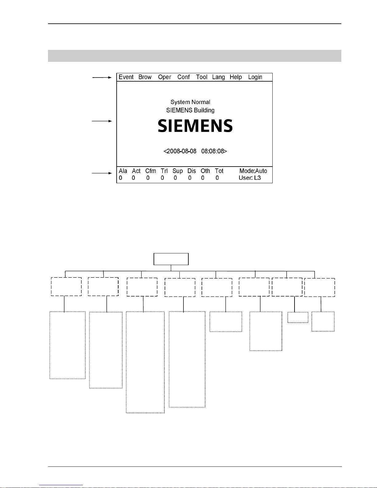
2. LCD WINDOW
FC18 controller has 3 windows which are menu window (1), browser window (2) and statistics window (3).
① Menu window:
¹ Display different operation menus according to different user levels. Items for Level 3 are shown as follows.
Fig. 3-2 Display screen
③①②
Main menu
Operate
—Alarm & active
—Trouble
—Supervision
—Disable
—Test
—Walk-test
—Locat e
—Disable
—Enable
—Open
—Close
—Activate
—Deactivate
—Test
—Walk-test
—Restore
—Locat e
—Stop locating
—Edit parameter
—Save configure
—Assign group
—Assign FRT
—Equipment
repl acement
—Create logic.
—View logic
—Edit logic
—Delet e logic
—English
—Taiwan
—HongKong
—Portugal
—About
BrowseEvent
Tool
Help
Configure Login
—All
—Unconfigure
—Unknown
—Inconsistent
—Exchange
—History
—Property
—Others
—Login
—Logout
Lang
—Set time
—Check
system
Page 18

Operating Manual of FC18 Controller
Page: 17/63
② Browser window:
¹ Display real-time events: fire alarm, activation & confirmation, trouble, supervision, disable, test and walk-test.
¹ Display node tree.
¹ Priority of display: fire alarm→ activation & confirmation→ supervision→ disable→ trouble→ test/walk-test→ normal.
③ Statistics window:
¹ Display total number of real-time events including fire alarm, activation, confirmation, trouble, supervision and disable.
¹ Display the level of the present user as well as the system mode.
¹ icon is displayed when system clock is wrong, possible reason is : the button battery on main board is used or
clock chip can not work normally.
Page 19

Operating Manual of FC18 Controller
Page: 18/63
3. USER LEVEL
l FC18 has 3 user levels. User level is displayed at the lower right corner of the screen (Fig. 3-2)
l Users of different levels have their own matching privileges and interfaces.
Table 3-1 user privilege list
It em Level 1 Level 2 Level 3
Login √
Logout √ √
Real-time event query √ √ √
History query √ √ √
Property query √ √ √
Disable/Enable devices √ √
Activation/Deactivation devices √ √
Test √ √
Walk-test √ √
Restore √ √
Locate √ √
Stop locating √ √
Login time setting √
Buzzer level setting √
LCD closing time setting √
System time setting √
Auto/manual mode setting √ √
Edit parameter √
Create logic √
Delete logic √
Edit logic √
View logic √
Print events √ √ √
Save configure √
Operate interlocking panel √ √
System check √
Acknowledge/Silence √ √
NAC √ √
Group assignment √
FRT assignment √
Change language √
Reset √ √
Page 20
Operating Manual of FC18 Controller
Page: 19/63
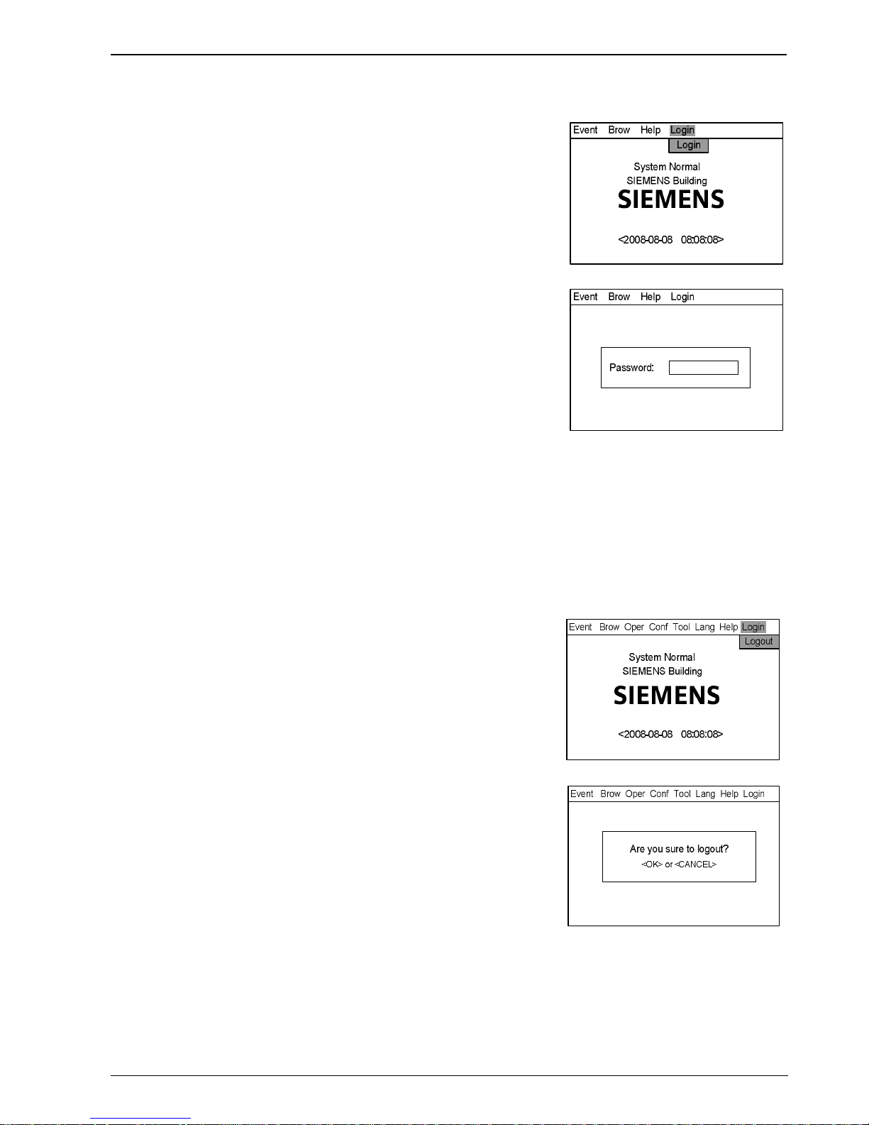
3.1 Login
1. Press “Menu” to browse the main menu.
Display main menu.
2. Press”→” to select “Login”, and then press “OK”.
Password entry window pops out.
3. Enter the password for Level2/3 and press “OK”.
Login as a Level 2/3 user if the password entered is correct.
(Press “←” to delete previous input.)
Note:
Default password for Level 2 is 1234, for Level 3 is 4321. Default password
can be changed by FXS1800 software tool.
System logout automatically after 3 times of invalid entries.
Fig. 3-3
Fig. 3-4
3.2 Logout
There are two ways to logout:
l System logout automatically: System autom atically logs out to Level 1 if no operations during a preset login time. (System
login time can be set by modifying station parameters.)
l Use the menu to logout:
1. Press “Menu” to browse the main menu.
Display event menu.
2. Press”→” to select “Login”, and then press “OK”.
Logout window pops out.
3. Press “OK” to return back to Level 1 interface; press “C” to cancel the logout
operation.
Note:
Users can directly login Level 2/3 interface under Level 1 interface; Users
need to return back to Level 1 interface before logging in Level 2 from Level
3 interface, also same from Level 2 to Level 3.
Fig. 3-5
Fig. 3-6
Page 21

Operating Manual of FC18 Controller
Page: 20/63
4. STATUS TYPES
FC18 controller contains 8 status types: normal, fire alarm/activation, trouble, supervision, disable, test/walk-test and locate.
Normal:
l Main power supply indicator on
l Auto/Manual indicator on
l No events taken place such as fire alarm/activation, trouble, supervision,
disable, test, walk-test etc.
l LCD shown as the figure
The screen shall show “System Normal” and project name.
SIEMENS
<2008-08-08 08:08:08>
System Normal
SIEMENS Building
Event Brow Help Login
Fig. 4-1
Fire alarm status:
l Fire alarm indicator on
l LCD shown as the figure
l Acknowledge/Silence indicator flashing
l NAC activation indicator on
l Buzzer ringing
l NAC device activated
0001 Auto Alarm 2008-08-08 10:10:10
Room 1001, Building 1 / 01.005.001
Alarm & Active
0002 Auto Alarm 2008-08-08 10:10:11
Room 1008, Building 1 / 01. 005.008
0001 Active 2008-08-08 10:10:11
Output 1 / 01.005.008
Fig. 4-2
Trouble status:
l Trouble indicator on
l LCD shown as the figure
l Acknowledge/Silence indicator flashing
l Buzzer ringing
0002 COMM trouble 2008-08-08 10:10:10
Interlocking Line / 01.005
Trouble
0001 Other 2008-08-08 10:10:08
Room 1008, Building 1 / 01. 001.291
Fig. 4-3
Supervision status:
l Supervision indicator on
l LCD shown as the figure
l Acknowledge/Silence indicator flashing
l Buzzer ringing
Supervision
0001 Supervision 2008-08-08 10:10:15
Supervision 1 / 01.005.010
Fig. 4-4
Page 22

Operating Manual of FC18 Controller
Page: 21/63
Activation status:
l Activation indicator on (flashing when there is no confirmation)
l LCD shown as the figure
l Acknowledge/Silence indicator flashing
l Buzzer ringing
Activation
0001 Activation 2008-08- 08 10:10:13
Output 1 / 01.005.008
Fig. 4-5
Confirmation status:
l Confirmation indicator on
l LCD shown as the figure
l Acknowledge/Silence indicator flashing
l Buzzer ringing
Confirmation
0001 Confirmation 2008-08-08 10:10:11
Output 1 / 01.005.008
Fig. 4-6
Disable status:
l Disable indicator on
l LCD shown as the figure
0002 Disable 2008-08-08 10:10:10
Room 1001, Building 1 / 01.005.001
Disable
0001 Disable 2008-08-08 10:08:10
Room 1008, Building 1 / 01. 001.291
Fig. 4-7
Test/Walk-t est stat us:
l Test indicator on
l LCD shown as the figure
Test
0001 Test 2008-08-08 10:10:11
Room 1008, Building 1 / 01.0 05.008
Fig. 4-8
Locate status:
l No indication
l No interface, it only can be found in equipment properties.
Page 23

Operating Manual of FC18 Controller
Page: 22/63
5. FIRE ALARM EVENT HANDLING
Fire alarm status:
l Fire alarm indicator turns on
l Fire event with customer information shown in the LCD as the figure
l Acknowledge/Silence indicator flashing
l NAC activation indicator turns on
l Buzzer turns on
l NAC devices activated
How to handle:
1. Press Acknowledge/Silence to silence the buzzer:
l Under Level 1 interface, a login interface pops out automatically. Enter
Level 2/3 password and press “OK” to return back to fire alarm window
then press “Acknowledge/Silence”. Now,
- Buzzer is mute
- The Acknowledge/Silence indicator turns off
- NAC devices still in activation status
l Under Level 2/3 interface,
- Buzzer is mute
- The Acknowledge/Silence indicator turns off
- NAC devices still in activation status
2. Press “NAC Activation” to deactivate NAC devices and the indicator turns
off. Press it again to reactivate NAC devices and the indicator turns on. So
on and so forth.
3. Find out fire location from LCD.
4. Go to the site to investigate the situation.
5. Call the firemen immediately if it’s an emergency. If it’s controllable, press
“Reset” after handling the fire to remove the fire alarm event and the fire
alarm indicator turns off.
Handling mu lti-fire alarm:
- Information of multi-fire alarm is displayed.
- The cursor stays on the first alarm. Other alarms are displayed
repeatedly in a reverse order.
- Browsing each item by pressing ”↓” / ”↑“
Note: The re are 2 kin ds of fire al arms nam ely “auto alarm” an d “manual
alarm”.
Fig. 5-1fire alarm interface
Page 24

Operating Manual of FC18 Controller
Page: 23/63
6. TROUBLE EVENT HANDLING
Trouble status:
l Trouble indicator turns on
l Trouble events are shown on the LCD as the figure
l Acknowledge/Silence indicator flashing
l Buzzer turns on
How to handle:
1. Press “Acknowledge/Silence” to silence the buzzer:
l Under Level 1 interface, a login interface pops out automatically. Enter
Level 2/3 password and press “OK” to return back to fire alarm window
then press “Acknowledge/Silence”. Now,
- Buzzer is mute.
- The Acknowledge/Silence indicator turns off.
l Under Level 2/3 interface,
- Buzzer is mute
- The Acknowledge/Silence indicator turns off.
2. Find out the trouble location from LCD.
3. Go to the site to trouble-shoot.
4. The trouble indicator turns off when problems are solved. If you cannot solve
the problem, please call local Siemens service center.
Note:
When a trouble occurs together with another event of higher priority, trouble
event cannot be displayed automatically. Enter the trouble window manually
(see “real-time query” function) to handle trouble.
CPU trouble:
When application software in trouble or CPU hardware trouble occurs,
system trouble indicator turns on. In such case, system cannot operate
normally and no key is available. Now you should disconnect the power
supply and contact with Siemens service center.
Fig. 6-1
Page 25

Operating Manual of FC18 Controller
Page: 24/63
7. SUPERVISION EVENT HANDLING
Supervision status:
l Supervision indicator on
l Supervision events are shown on the LCD as the figure
l Acknowledge/Silence indicator flashing
l Buzzer turns on
How to handle:
1. Press “Acknowledge/Silence” to silence the buzzer:
l Under Level 1 interface, a login interface pops out automatically. Enter
Level 2/3 password and press “OK” to return back to fire alarm window
then press “Acknowledge/Silence”. Now,
- Buzzer is mute.
- The Acknowledge/Silence indicator turns off.
l Under Level 2/3 interface,
- Buzzer is mute
- The Acknowledge/Silence indicator turns off.
2. Find out the supervision location from LCD.
3. Go to the site to handle it if necessary.
4. The supervision event will disappear when supervision signal disappears.
Press “Reset” to turn off the supervision indicator and the controller return to
normal.
Note:
When a supervision event occurs together with another event of higher
priority, supervision event cannot be displayed automatically. Enter the
supervision window manually (see “real-time query” function) to handle it.
Fig.7-1
Page 26

Operating Manual of FC18 Controller
Page: 25/63
8. ACTIVATION/CONFIRMATION EVENT HANDLING
Activation status:
l Activation indicator on (flashing if there is no confirmation)
l Confirmation indicator on (only if there is confirmation signal)
l Activation events are shown on the LCD as the figure
l Acknowledge/Silence indicator flashing
l Buzzer turns on
How to handle:
1. Press Acknowledge/Silence to silence the buzzer:
l Under Level 1 interface, a login interface pops out automatically. Enter
Level 2/3 password and press “OK” to return back to fire alarm window
then press “Acknowledge/Silence”. Now,
- Buzzer is mute.
- The Acknowledge/Silence indicator turns off.
l Under Level 2/3 interface,
- Buzzer is mute
- The Acknowledge/Silence indicator turns off.
2. Find out the activation/confirmation location from LCD.
3. Go to the site to handle it if necessary.
4. Confirmation indicator turns off when confirmation signal disappears. When
activation signal disappears, press “Reset” to turn off the activation indicator
and the controller return to normal.
Note:
- When an activation/confirmation event occurs together with another
event of higher priority, activation/confirmation event cannot be
displayed automatically. Enter the activation/confirmation window
manually (see “real-tim e query” function) to handle it.
- Press “←” to switch between fire alarm window and activation window.
Fig.8-1activation interface
Page 27

Operating Manual of FC18 Controller
Page: 26/63
9. REAL-TIME QUERY
FC18 fire alarm controller (interlocking) contains ten types of real-time events:
Table 3-2
T ypes of real-time events Priority
Fire alarm/activation 1
Supervision 2
Disable 3
Trouble 4
Test 5
Walk-test 5
Locate 5
Unconfigure equipment 6
Unknown equipment 7
Inconsistent equipment 8
Exchange equipment 9
Unconfigure equipment: Equipments not on the engineering document list.
Unknown equipment: Equipments not listed by Table 1-2.
Inconsistent equipment: The type of installed equipment on site is inconsistent with engineering document.
Exchange equipment: Dirty smoke detector.
Steps:
1. Press “Menu” to browse the main menu. (Fig. 9-1)
Main menu displayed.
2. Press “↓” to select an event type to query then press “OK”.
All the events meeting the requirements will be displayed in the window. Use
“↓” /”↑” to browse items.
When an event is selected, press “→” to pop out a shortcut menu (Fig. 9-2). All
operable items will be listed according to user’s level. Use “↓” / “↑” to select
an operation then press “OK” to take the operation.
Note:
- “0001”: Order of an event
- “COMM trouble”: Type of an event
- “2008-08-08 10:10:10”: Date and time when an event takes place
- “Interlocking line / 01.0005”: Text message and equipment address of an
event
- “Interlocking group”: text message of the group which this interlocking
equipment belongs to. (If the equipment does not belong to any group,
only text message of the event and equipment address are displayed.)
SIEMENS
<2008-08-08 08:08:08>
System Normal
SIEMENS Building
Event Brow Help Login
Alarm & active
Trouble
Supervision
Disable
Test
Walk-Test
Locate
Alarm & active
Fig. 9-1
0002 COMM trouble 2008-08-08 10:10: 10
Interlocking Line / 01.005
Trouble
0001 Other 2008-08-08 10:10:08
Room 1008, Building 1 / 01.001.291
Property
History
Disable
Test
Property
Fig. 9-2
Page 28

Operating Manual of FC18 Controller
Page: 27/63
10. HOW TO QUERY EQUIPMENT PROPERTY
Steps:
1. Select a station, a line or a point and press “→” to pop out a shortcut menu
(Fig. 10-1), then select “Property” and press “OK” to pop out a property
window. (Fig. 10-2)
2. Press “C” to quit equipment property query.
0002 COMM trouble 2008-08-08 10:10:10
Interlocking Line / 01.005
Trouble
0001 Other 2008-08-08 10:10:08
Room 1008, Building 1 / 01. 001.291
Property
History
Property
Fig.10-1
Station ID: 1
Line ID: 1
Point ID: 3
Text: Room 1008, Building 1
Type: Heat detectot
Status: Normal
Property
Fig.10-2
Page 29

Operating Manual of FC18 Controller
Page: 28/63
11. HOW TO QUERY HISTORY
FC18 fire alarm controller (interlocking) contains 11 types of history records which are fire alarm, trouble, supervision,
activation/confirmation, disable, test and walk-test, unconfigure equipment, unknown equipment, inconsistent equipment,
exchange equipment. The first six types support advanced query.
Steps:
1. Select a station, a line or a point and press “→” to pop out a shortcut menu,
and then press “↓” to “History” (Fig. 11-1). Press “OK” to pop out the
record window. All the history records will be displayed. (Fig. 11-2)
Note:
If a system is selected, all the history records of all the stations, lines and
points belonging to this system are displayed.
If a station is selected, all the history records of this station and the line and
equipment which belongs to this station will be displayed.
If a line is selected, all the history records of this line will be displayed.
If a point is selected, all the history records of this point will be displayed.
2. Press “Menu” to pop out the record menu, select “Advanced Query”
(Fig.11-3), then press “OK” to pop out advanced query window (Fig.11-4).
3. Select a type and input query time period then press “OK”. All the events
meet the requirements will be displayed in the window. Use “↓” /”↑” to
browse items then press “Menu”:
Select “Print” to print all the history records displayed.
Select “Quit” to return back to initial interface.
Note:
Use “↓” / “↑” to switch active window.
Use “→” to activate the dropdown menu of types.
Use “←” to clear wrong input.
Date format:YYYY-MM-DD; time format: HH-MM-SS.
0002 COMM trouble 2008-08-08 10:10: 10
Interlocking Line / 01.005
Trouble
0001 Other 2008-08-08 10:10:08
Room 1008, Building 1 / 01.001.291
Property
History
History
Fig.11-1
+ 001 Disable 01.005.001
Room 1001, Building 1
2008-08-08 10:10:10
Record
+ 002 Disable 01.001.291
Room 1008, Building 1
2008-08-08 10:11:10
Fig.11-2
+ 001 Disable 01.005.001
1号楼1001室
2008-08-08 10:10:10
Record
+ 002 Disable 01.001.291
Room 1008, Building 1
2008-08-08 10:11:10
Print
Quit
Advanced Query
Fig.11-3
+ 001 Disable 01.005.001
Room 1001, Building 1
2008-08-08 10:10:10
Record
+ 002 Disable 01.001.291
Room 1008, Building 1
2008-08-08 10:11:10
Advanced Query: Type
Start Time End Time
All
2008-08-08
08:08:08
2008-08-09
10:10:10
Fig.11-4
Page 30

Operating Manual of FC18 Controller
Page: 29/63
12. HOW TO DISABLE/ENABLE
Function: The controller should be disabled when the house is being decorated
or there are equipment damages or failure. It should be resumed to
normal state as soon as the decorating work or equipment repair is
finished.
Note: Disabled equipment cannot send any message to controller.
Equipment cannot be disabled when being replaced.
Steps to disable:
1. Press “Menu” to browse the main menu (Fig.12-1).
Main menu displayed.
2. Press “→” to select “Brow” submenu (Fig. 12-2). Press “↓” to select the
item which contains the equipment to be disabled, and then press “OK”.
Now the equipment will be displayed directly in the window.
If you don’t know which type the equipment to be disabled belongs to,
please select “All equipments”, then press “OK” to display the tree (Fig.
12-3). Search down level by level through stations, lines and points until
you find the equipment you are looking for.
3. Press “→” to pop out the shortcut menu (Fig.12-4). Use “↓” to select
“Disable” and press “OK” to disable the selected equipment.
Steps to enable (two ways):
The first way: the same as the steps to disable. The only difference is that select
“Enable” instead of “Disable” in step 3.
The second way: it’s easier to find the disable equipment through real-time
disable query (see real-time query). Press “→” to pop out the shortcut
menu (Fig. 12-5) and press “↓” to select “Enable”, then press “OK” to
enable the selected equipment.
Disable indicator goes off when all the disable equipments are enabled.
Fig.12-1
Fig.12-2
Fig.12-3
Fig.12-4
Fig.12-5
Page 31

Operating Manual of FC18 Controller
Page: 30/63
13. HOW TO ACTIVAT E/DEACT IVATE THE CONTROLLER
Function: Through controller, manually activation/deactivation mainboard
output, output module, interlocking panel output and NAC devices etc.
Steps to activation:
1. Press “Menu” to browse the main menu (Fig. 13-1).
Main menu displayed.
2. Press “→” to select “Brow” submenu (Fig. 13-2). Press “↓” to select “All”,
then press “OK” to display the tree diagram (Fig. 13-3). Search down level
by level through stations, lines and points until you find the equipment you
are looking for.
3. Press “→” to pop out a shortcut menu (Fig.13-4). Use “↓” to select
“Activate” and press “OK” to activate the selected equipment.
4. Press “Acknowledge/Silence” to silence the buzzer and to turn off the
flashing “Acknowledge/Silence” indicator.
Steps to deactivate (two ways):
The first way: the same as the first 2 steps to activation. The only difference is
that select “Deactivate” instead of “Activate” in step 3.
The second way: It’s easier to find the activated equipment through real-time
activation query (see real-time query). Press “ →” to pop out a shortcut
menu (Fig. 13-5) and press “↓” to select “Deactivate”, then press “OK”
to deactivate the selected equipment.
Activation indicator turns off when all the activated equipments are
deactivated.
Fig.13-1
Fig.13-2
All
NAC
SIEMENS Buidling
Building 1 Controller
Power Monitor Line
Onboard I/O
Main Board I/O 2
Main Board I/O 1
P2 Line
Fig.13-3
All
NAC
SIEMENS Buidling
Building 1 Controller
Power Monitor Line
Onboard I/O
Main Board I/O 2
Main Board I/O 1
P2 Line
Property
History
Activate
Disable
Edit Parameter
Activate
Fiig.13-4
Fig.13
-
5
Page 32

Operating Manual of FC18 Controller
Page: 31/63
14. HOW TO TEST/WALK-TEST
Function: To test whether the alarm device is in normal status. Under
test/walk-test mode, an alarm will be triggered when there is an alarm
event while the interlocking equipment will not be activated. Make sure the
controller is back to normal after the test.
Difference between test and walk-test:
Test: Fire alarms cannot reset automatically under test mode. Controller
need to be resumed back to normal status by manual reset.
Walk-test: Controller can resume back to normal status automatically after
the preset walk-test time (which can be set by editing the
controller parameters).
Steps to tes t/w alk-test:
1. Press “Menu” to browse the main menu (Fig. 14-1).
Main menu displayed.
2. Press “→” to select “Brow” submenu (Fig. 14-2). Press “↓” to select “All”,
then press “OK” to display the tree diagram (Fig. 14-3). Search down level
by level through stations, lines and points until you find the equipment you
are looking for.
3. Press “→” to pop out the shortcut menu (Fig.14-4). Use “↓” to select
“Test/Walk-Test” and press “OK” to test the selected equipment.
How to restore to normal: two ways
The first way: the same as the first 2 steps to conduct a test/walk-test. The only
difference is that select “Restore” instead of “Test/Walk-Test” in step 3.
The second way: It’s easier to find the tested equipment through real-time
test/walk-test query (see real-time query). Press “→” to pop out the
shortcut menu (Fig. 14-5) and press “↓” to select “Restore”, then press
“OK” to restore the selected equipm ent.
Test/walk-test indicator turns off when all the tested equipments are
restored to normal.
Fig.14-1
Fig.14-2
Fig.14-3
Fig.14-4
Fig.14-5
Page 33

Operating Manual of FC18 Controller
Page: 32/63
15. HOW TO LOCATE/STOP LOCAT ING
Function: To locate equipment.
Steps to locate:
1. Press “Menu” to browse the main menu (Fig. 15-1)
Main menu displayed.
2. Press “→” to select “Brow” submenu (Fig. 15-2). Press “↓” to select “All”,
then press “OK” to display the tree diagram (Fig. 15-3). Search down level
by level through stations, lines and points until you find the equipment you
are looking for.
3. Press “→” to pop out the shortcut menu (Fig.15-4). Use “↓” to select
“Locate” and press “OK” to locate the selected equipment. Now the test
indicator is flashing.
Steps to stop locating:
The same as the first 2 steps to conduct a remote test. The only difference
is that select “Stop locating” instead of “Locate” in step 3. Then press "OK"
to reset the selected equipment and turn off the flashing indicator.
Fig.15-1
Fig.15-2
Fig.15-3
Fig.15-4
Page 34

Operating Manual of FC18 Controller
Page: 33/63
16. HOW TO ADJUST BUZZER LEVEL
Function: Turn up or down the buzzer between level 0-7. Level 0 is mute mode.
Steps:
1. Press “Menu” to browse the main menu (Fig. 16-1)
Main menu displayed.
2. Press “→” to select “Brow” submenu (Fig. 16-2). Select "All" and then press
“OK”. Now the tree diagram will be displayed in the window (Fig.16-3).
3. Use "↓" / "↑" to select the controller you are looking for.
4. Press “→” to pop out the shortcut menu (Fig.16-4). Use “↓” to select “Edit
Parameter” and press “OK” to enter the parameter editing interface
(Fig.16-5).
5. Press "↓" to select "Buzzer Level" window. Press "←" to delete the
previous number and enter the expected one.
6. After the change, press "Menu" and press "↓" to select "Confirm", then
press "OK" to save the change and quit. A dialog box will pop out to remind
you to save the change (Fig. 22-3). Press "OK" to save the change
permanently or press "C" to save the change temporarily. (The change will
be lost if the system is restarted.)
Select "Cancel" and press”OK” if you don't want to save the change.
Note:
·The saved changes take effect immediately.
·These operations can only be applied to the selected controller.
Fig.16-1
Fig.16-2
Fig.16-3
Fig.16-4
Fig.16-5
Page 35

Operating Manual of FC18 Controller
Page: 34/63
17. HOW TO SET LO GIN TIME
Function: Under 2/3 level, if there is no operation in preset login time, controller
will autom atically log out to 1level. Setting range: 1-60 minutes.
Steps:
1. Press “Menu” to browse the main menu (Fig. 17-1)
Main menu displayed.
2. Press “→” to select “Browse” submenu (Fig. 17-2). Select "All" and then
press “OK”. Now the tree diagram will be displayed in the window
(Fig.17-3).
3. Use "↓" / "↑" to select the controller you are looking for.
4. Press “→” to pop out the shortcut menu (Fig.17-4). Use “↓” to select “Edit
Parameter” and press “OK” to enter the parameter editing interface
(Fig.17-5).
5. Press "↓" to select "Login Time" window. Press "←" to delete the previous
number and enter the expected one.
6. After the change, press "Menu" and press "↓" to select "Confirm", then
press "OK" to save the change and quit. A dialog box will pop out to remind
you to save the change (Fig. 22-3). Press "OK" to save the change
permanently or press "C" to save the change temporarily. (The change will
be lost if the system is restarted.)
Select "Cancel" and press”OK” if you don't want to save the change.
Note: The saved changes take effect immediately.
These operations can only be applied to the selected controller.
Fig.17-1
Fig.17-2
Fig.17-3
Fig.17-4
Fig.17
-
5
Page 36

Operating Manual of FC18 Controller
Page: 35/63
18. HOW TO SET WALK-TEST TIME
Function: Controller being tested will restore to normal status automatically after
the preset walk-test time. Setting range: 1-60 min.
Steps:
1. Press “Menu” to browse the main menu (Fig. 18-1)
Main menu displayed.
2. Press “→” to select “Brow” submenu (Fig. 18-2). Select "All" and then press
“OK”. Now the tree diagram will be displayed in the window (Fig.17-3).
3. Use "↓" / "↑" to select the controller you are looking for.
4. Press “→” to pop out the shortcut menu (Fig.18-4). Use “↓” to select “Edit
Parameter” and press “OK” to enter the parameter editing interface
(Fig.18-5).
5. Press "↓" to select "Walk-Test" window. Press "←" to delete the previous
number and enter the expected one.
6. After the change, press "Menu" and press "↓" to select "Confirm", then
press "OK" to save the change and quit. A dialog box will pop out to remind
you to save the change (Fig. 22-3). Press "OK" to save the change
permanently or press "C" to save the change temporarily. (The change will
be lost if the system is restarted.)
Select "Cancel" and press”OK” if you don't want to save the change.
Note: The saved changes take effect immediately.
These operations can only be applied to the selected controller.
Fig.18-1
Fig.18-2
Fig.18-3
Fig.18-4
Fig.18
-
5
Page 37

Operating Manual of FC18 Controller
Page: 36/63
19. HOW TO SET LCD CLOSING TIME
Function: LCD turns off its back light if there is no operation or event during the
preset LCD closing time. Press any key to turn on the back light. Setting
range: 1-60 min.
Steps:
1. Press “Menu” to browse the main menu (Fig. 19-1)
Main menu displayed.
2. Press “→” to select “Browse” submenu (Fig. 19-2). Select "All" and then
press “OK”. Now the tree diagram will be displayed in the window
(Fig.19-3).
3. Use "↓" / "↑" to select the controller you are looking for.
4. Press “→” to pop out the shortcut menu (Fig.19-4). Use “↓” to select “Edit
Parameter” and press “OK” to enter the parameter editing interface
(Fig.19-5).
5. Press "↓" to select "LCD closing time" window. Press "←" to delete the
previous number and enter the expected one.
6. After the change, press "Menu" and press "↓" to select "Confirm", then
press "OK" to save the change and quit. A dialog box will pop out to remind
you to save the change (Fig. 22-3). Press "OK" to save the change
permanently or press "C" to save the change temporarily. (The change will
be lost if the system is restarted.)
Select "Cancel" and press”OK” if you don't want to save the change.
Note: The saved changes take effect immediately.
These operations can only be applied to the selected controller.
Fig.19-1
Fig.19-2
Fig.19-3
Fig.19-4
Fig.19
-
5
Page 38

Operating Manual of FC18 Controller
Page: 37/63
20. HOW TO SET TIME
Function: To set system time.
Steps:
1. Press “Menu” to browse the main menu (Fig. 20-1)
Main menu displayed.
2. Press “→” to pop out the "Tool" submenu (Fig.20-2). Select “Set Time" and
press “OK” to enter the time setting interface (Fig.20-3).
3. Press "←" to delete the previous number and enter the exact time and date
then press "OK". The change will take effect immediately.
Note: A master controller can be set as a time-based controller by FXS1800
engineering tool. The time-based controller synchronizes other slave
controller every one hour. Salve controller can not be synchronized
when system rest art.
Fig.20-1
Fig.20-2
Fig.20-3
Page 39

Operating Manual of FC18 Controller
Page: 38/63
21. HOW TO CHECK SYSTEM
Function: To check whether the LCD, indicators, printer and the buzzer are in
normal state.
Steps:
1. Press “Menu” to browse the main menu (Fig. 21-1)
Main menu displayed.
2. Press “→” to pop out the "Tool" submenu (Fig.21-2). Press "↓" to select
“Check System" and press “OK” to display the checking system window
(Fig.21-3). Press "OK" to examine the system.
- LCD: Flash in white and black once for each. It's normal if there is no
blank spot.
- Indicator: All indicators flashing. Any indicator not flashing is broken.
- Buzzer: Rings in 4 different sounds. The sound system is abnormal if
there is sound missed.
- Printer: Print "successful test!" automatically. It's broken if it fails to print
them.
3. After finishing checking system, it will return to the original interface.
Fig.21-1
Fig.21-2
Fig.21-3
Page 40

Operating Manual of FC18 Controller
Page: 39/63
22. HOW TO SAVE CONFIGURE
Function: Save changes permanently, otherwise the changes will be lost when
the system is restarted.
Steps:
1. Press “Menu” to browse the main menu (Fig. 22-1)
Main menu displayed.
2. Press “→” to pop out the "Conf" submenu (Fig.22-2). Press "↓" to select
“Save Configure" and press “OK” to display the configuration saving
window (Fig.22-3). Press "OK" to save the changes.
3. It will return to the original interface after the changes are saved.
Fig.22-1
Fig.22-2
Fig.22-3
Page 41

Operating Manual of FC18 Controller
Page: 40/63
23. HOW TO EDIT PARAMETER
Function: To modify parameters in system. See Appendix table 1 for details.
Steps:
1. Press “Menu” to browse the main menu (Fig. 23-1)
Main menu displayed.
2. Press “→” to select “Brow” submenu (Fig. 23-2). Press “↓” to select the
item which contains the equipment whose parameters need to be modified,
and then press “OK”. Now the equipment will be displayed derectly in the
window.
If you don’t know which type the equipment belongs to, please select “All”,
then press “OK” to display the tree diagram (Fig. 23-3). Search down level
by level through stops, loops and points until you find the equipment you
are looking for.
3. Press “→” to pop out a shortcut menu (Fig.23-4). Use “↓” to select “Edit
Parameters” and press “OK” to enter the parameter modify interface
(Fig.23-5).
4. Operations to modify:
- Press “↓”/” ↑” to switch between windows.
- If it is numerical value type of item, press “←” to delete the previous
number and then enter the expected one.
- If it is a pull-down menu, press "→" to pop out the pull-down menu,
and then press “↓” to choose, then press “OK” to confirm.
5. After the modification, press "Menu" and press "↓" to select "Confirm",
then press "OK" to save the change and quit. A dialog box will pop out to
remind you to save the change (Fig. 16-6). Press "OK" to save the change
for permanence or press "C" to save the change temporarily. (The change
will be lost if the system is restarted.)
Select "Cancel" and press”OK” if you don't want to save the change.
Note: The saved changes take effect immediately.
These operations can only be applied to the selected controller.
Fig.23-1
Fig.23-2
Fig.23-3
Fig.23-4
Fig.23
-
5
Page 42

Operating Manual of FC18 Controller
Page: 41/63
24. HOW TO CREAT E/VIEW LOGIC
Function: To create/view logic among detection group, supervision group and
control output group.
Steps:
1. Press “Menu” to browse the main menu (Fig. 24-1)
Main menu displayed.
2. Press “→” to select “Brow” submenu (Fig. 24-2). Select "All" and then press
“OK”. Now the tree diagram will be displayed in the window (Fig.24-3).
Press “↓”/” ↑” to find out the group for which you want to build a interlock.
3. Press “→” to pop out the shortcut menu (Fig.24-3). Use “↓” to select
“Create Logic” and press “OK” to enter the logic interface (Fig.24-4). The
address of the group chosen is shown in the editing window automatically.
Users can input an interlocking expression according to "Rules for editing
interlocking" (see Appendix table 4).
4. After modification/entering, press “Menu” (Figure 24-5), select “Confirm”,
and then press “OK” to begin system compiling. If successful, it will display
“Logic relations compiled successfully”. If not successful, display will
indicate error information. If you don’t want to save this change, select
“Cancel”, and press “OK” to quit.
5. After the change, press "Menu" and press "↓" to select "Confirm", then
press "OK" to save the change and quit. A dialog box will pop out to remind
you to save the change (Fig. 22-3). Press "OK" to save the change for
permanence or press "C" to save the change temporarily. (The change will
be lost if the system is restarted.)
Select "cancel" and press “OK” if you don't want to save the change.
Note: The saved changes take effect immediately.
These operations can only be applied to the selected controller.
"0" can be neglected in expressions because the system will add it
automatically.
6. Select "View Logic" in step 3 to enter the view window which includes all
the logical expressions of the selected group. You cannot edit interlock in
the view window. Press "C" to quit after the view.
Note: These operations can be applied to both host machine and slaves.
Fig.24-1
Fig.24-2
Fig.24-3
Fig.24-4
Fig.24-5
Page 43

Operating Manual of FC18 Controller
Page: 42/63
25. HOW TO EDIT/DELETE LOGIC
Function: To modify or delete logic.
Steps:
1. Press “Menu” to browse the main menu (Fig. 25-1)
Main menu displayed.
2. Press “→” to select “Browse” submenu (Fig. 25-2). Select "All" and then
press “OK”. Now the tree diagram will be displayed in the window
(Fig.25-3). Press “↓”/” ↑” to find out the expression to be modified.
3. Press “→” to pop out the shortcut menu (Fig.25-3). Use “↓” to select
“Edit Logic” and press “OK” to enter the logic interface (Fig.25-4). Then
users can edit the selected expression.
4. After editing, press “menu” (Figure 25-5), choose “Confirm”, and then
press “OK” to begin system compiling. If successful, it will display “Logic
relations compiled successfully”. If not successful, display will indicate
error information. If you don’t want to save this change, select “Cancel”,
and press “OK” to quit.
5. A dialog box will pop out to remind you to save the change (Fig. 22-3)
after you quit the edit window. Press "OK" to save the change
permanently or press "C" to save the change temporarily. (The change
will be lost if the system is restarted.)
6. If you select "Delete Logic" in step 3, the system will pop out a remind
window (Fig.25-5). Press "OK" to delete the interlock or press "C" to give
up.
This operation is temporary. Repeat step 5 to save the change
permanently.
Note: The saved changes take effect immediately.
These operations can only be applied to the selected controller.
"0" can be neglected in expressions because the system will add
it automatically.
Fig.25-1
Fig.25-2
Fig.25-3
Fig.25-4
SIEMENS
<2008-08-08 08:08:08>
Are you sure to delete logic?
<OK> or <CANCEL>
Event Brow Oper Conf Tool Lang Help Login
Fig.25-5
Page 44

Operating Manual of FC18 Controller
Page: 43/63
26. HOW TO ASSIGN GROUP/ FRT
Function: It's more convenient to edit logic with the concept of "Group". There
are four groups in the system: detection group, control output group, supervision
group and FRT group. See Appendix table 3 for details.
Steps:
1. Press “Menu” to browse the main menu (Fig. 26-1)
Main menu displayed.
2. Press “→” to select “Brow” submenu (Fig. 26-2). Select "All" and then press
“OK”. Now the tree diagram will be displayed in the window (Fig.26-3).
Press “↓”/” ↑” to find out the equipment to be assigned to group.
3. Press “→” to pop out a shortcut menu (Fig.26-3). Use “↓” to select “Assign
Group” or "Assign FRT"and press “OK” to enter the grouping interface
(Fig.26-4).
4. Press “→” to popup pull-down menu of groups that can be assigned to,
choose expected group, press “OK”, and system will save and return to the
original window. But the save here is just temporary; if the equipment is
reloaded, changed data will lost. As a result, for long-term storage, please
refer to “how to save configuration”. If you don’t want to save this change,
press “C”.
Note: The saved changes take effect immediately.
These operations can only be applied to the selected controller.
Fig.26-1
Fig.26-2
Fig.26-3
Fig.26-4
Page 45

Operating Manual of FC18 Controller
Page: 44/63
27. HOW TO GET HELP
Function: To show the company name, system edition, product series No,
download time of configuration file and modification time.
Steps:
1. Press “Menu” to browse the main menu (Fig. 27-1)
Main menu displayed.
2. Press “→” to select “Help” submenu (Fig. 27-2). Press "OK" to display the
help information window (Fig.27-3).
3. Press "C" to return to the original window.
Fig.27-1
Fig.27-2
Fig.27-3
Page 46

Operating Manual of FC18 Controller
Page: 45/63
28. HOW TO OPERAT E INTERLOCKING PANEL
Function: The interlocking penal has 8 channels of input/output. Each of them has indicators of trouble, activation and
confirmation to indicate its state, as well as activation/deactivation key for manual control.
Steps:
¹ When the controller is in automatic status, the controller can activate spot equipment through logical relation. The
"activation" indicator is on when activation order is given. The "confirmation" indicator is on when confirmation signal is
received.
¹ When the controller is in manual status, spot equipment can be activated/deactivated manually. "Activation" indicator
is on when "Activation/Deactivation" key is pressed. "Confirmation" indicator is on when confirmation signal is
received. When "Activation/Deactivation" is pressed, "activation" indicator is off and the equipment output stops.
¹ Trouble indicator is on when trouble occurs during examination. It is off when the trouble is solved.
Page 47

Operating Manual of FC18 Controller
Page: 46/63
29. HOW TO OPEN/CLOSE A PRINTER
Function: When the printer is open, it can print real-time events at any time and
print history records if needed (see "History Query"); when it is off, it
cannot print anything.
Steps to open printer:
1. Press “Menu” to browse the main menu (Fig. 29-1)
Main menu displayed.
2. Press “→” to select “Brow” submenu (Fig. 29-2). Select "All" and then press
“OK”. Now the tree diagram will be displayed in the window (Fig.29-3).
Usually printer is under mainboard port.
3. Press “→” to pop out the shortcut menu (Fig.29-4). Use “↓” to select
“Open” and press “OK” to open the printer.
Steps to close p rin ter:
The same as the steps to turn it on. The only difference is to select “Close”
instead of “Open” in step 3 (Fig.29-5). Then press "OK" to close printer.
Note: Open/close a printer is neither an event nor a history record.
Checking system does not change the status of the printer.
Fig.29-1
Fig.29-2
Fig.29-3
Fig29-4
Fig.29-5
Page 48

Operating Manual of FC18 Controller
Page: 47/63
Operations of printer:
There are two indicators and two keys. Indicators are under the transparent key.
Indicator:
Green indicator indicates electrifying state of printer; red indicator indicates
working state of printer (online/offline).
Green
indicator
On Normal power supply
Off No power supply
Red indicator
On Online
Off Offline
Keys:
SEL: Choose online/offline states of printer; LF: Line feed.
Self examination: To check whether:the printer is normal. Operation steps:
- Before electrified, press SEL and then connect 5V power supply, and
printer will print "self-examination".
- When printer is electrified, if indicator is on, press SEL to turn it off (if
indicator is off, this operation is not necessary). Press LF, and press
SEL, then the printer will print self-examination.
Press SEL to stop during self examination if needed.
Change paper roll:
1. As Fig.29-6, press the key to open the front cover.
2. Take out the left paper roll, and install the new one as Fig.29-7.
3. As Figure 29-8, close the front cover.
Note:
When close the front cover, let some of paper leave out of the exit to
make sure the plastic shaft is pressing it tightly.
Make sure heat-sensitive coat of print paper is on the front otherwise
nothing can be printed on the paper.
The printer state can be saved when panel power off.
Fig.29-6
Fig.29-7
Fig.29-8
Page 49

Operating Manual of FC18 Controller
Page: 48/63
30. HOW TO REPLACE DEVICE
Function: To copy the configuration information to the new equipment when the
old one is replaced.
Steps:
1. Press “Menu” to browse the main menu (Fig. 30-1)
Main menu displayed.
2. Press “→” to select “Browse” submenu (Fig. 30-2). Press "↓" to select "
Unconfigure" and then press “OK”. Now the equipments unconfigure will be
displayed in the window (Fig.30-3).
3. Press "↓" to select equipment to configure. Press “→” to pop out the
shortcut menu (Fig.30-4). Use “↓” to select “Equipment Replacement” and
press “OK” to enter the equipment replacement interface.
4. Press “→” to pop out the pull-down menu (Figure 30-5), and all equipments
that can be replaced will be displayed. Press “↓”/” ↑” to choose
equipments that need to be replaced, and press “OK”. System returns to
the original window.
But the save here is just temporary; if the equipment is restarted, the
change will be lost. For long-term storage, please refer to “how to save
configuration”. If you don’t want to save this change, press “Quit” to quit.
Note: The saved change will not take effect until the system is restarted.
Fig.30-1
Fig.30-2
Fig.30-3
Fig.30-4
Fig.30
-
5
Page 50

Operating Manual of FC18 Controller
Page: 49/63
31. HOW TO UPGRADE TO FC1840
Function: The FC18 wall-mounted controller has two types: the FC1820 and the
FC1840. FC1820 can be upgraded to FC 1840 through adding a loop card and
conducting the following operations.
Steps:
1. Press “Menu” to browse the main menu (Fig. 31-1)
Main menu displayed.
2. Press “→” to select “Brow” submenu (Fig. 31-2). Select "All" and then press
“OK”. Now the tree diagram will be displayed in the window (Fig.31-3). Use
"↓" / "↑" to select the host machine.
3. Press “Menu” to browse the main menu then press “→” to select “Oper”
submenu. Select "upgrade to FC1840" (Fig.31-3) then press "OK".
4. System pop out dialog window to ask user whether to upgrade or not
(Fig.31-4). Press "OK" to upgrade to FC1840 or press "C" to give up.
Note:
The saved change will not take effect until the system is reset.
This operation can only be applied to host machine.
This operation can only be applied to FC1820.
FC1840 cannot be degraded to FC1820. If it's needed, it should be
done through PC and downloading configuring files.
System Normal
SIEMENS Building
SIEMENS
<2008-08-08 08:08:08>
System Normal
Event Brow Oper Conf Tool Help Login
SIEMENS Building
Alarm & active
Trouble
Supervision
Disable
Test
Walk-Test
Alarm & active
Fig.31-1
Fig.31-2
Fig.31-3
Fig.31-4
Page 51

Operating Manual of FC18 Controller
Page: 50/63
32. HOW TO CHANGE LANGUAGE
Function: The system provides four kinds of language: English, Taiwan,
Hongkong, and Portuguese. Apply languages as needed.
Steps:
1. Press “Menu” to browse the main menu (Fig. 32-1).
Main menu displayed.
2. Press “→” to select “Lang” submenu (Fig. 32-2). Select a language you
need and press “OK”.
3. The system language is changed.
Note:
The saved change will take effect immediately.
This operation can only be applied to host machine.
Fig.32-1
Fig.32-2
Page 52

Operating Manual of FC18 Controller
Page: 51/63
33. HOW TO QUERY THE INFORMAT ION OF OTHER EVENTS
Function: Other events include: Test, Walktest, Locate, Unconfigure,
Unknown, Inconsistent, and Exchage. Through this function, can
check the qty for each event.
Step:
1. Press “Menu” to browse the main menu (Fig. 33-1).
Main menu displayed.
2. Press “→” to select “Brow” submenu (Fig. 33-2). Press “↓” to select
“Other”, and then press “OK” to display the information (Fig. 33-3).
3. Press "C" to return to the original window.
Fig. 33-1
Fig. 33-2
Fig. 33-3
Page 53

Operating Manual of FC18 Controller
Page: 52/63
CHAPTER 4 MAINTENANCE
1. DA ILY EXAMIN ATION
Operator on duty should examine controllers every day and record status. If there is fire alarm, error or other abnormal status,
please follow “Emergency Failure Guideline”; when controller gets normal again, the event should be recorded.
2. EMERGENCY AND TROUBLE HANDLING
Table 4-1
No. Fai lure phenomenon Cause analysis Solving Method
1.
Failure or damage of
function keys, LED,
LCD, etc.
Error of signal line, power line
Corresponding hardware trouble;
Ensure proper installation of
wiring; Change corresponding
hardware;
2.
No voltage indication of
controller
Whether main and backup power is on;
Whether power lines inside controller is firm
enough
Power trouble;
Ensure proper installation of
the power wiring; Check
power lines
Change power supply;
3.
Controller “black screen”
with voltage
No power supply for LCD or power supply
component of main board failure;
LCD trouble;
Wire connection loosening
Check power lines or change
main board;
Change LCD;
Check the wire connection
4.
No display of controller
System software or engineer software lost;
CPU trouble;
Change corresponding
software;
Change CPU;
5.
No sound
No voltage;
Not enough sound volume;
Beeper trouble;
Change power lines or main
board;
Adjust sound volume of
beeper;
Change beeper;
6.
Control station failure
Engineer software not in line with actual
equipment;
Address not set for main board or not in line
with software address;
Main board failure;
More than 2 controllers check A-BUS
communication and software configuration;
Examine whether A-Bus terminal resistance
connection is reasonable or not;
Change software;
Change configuration;
Change main board;
Examine A-BUS
communication line;
Reasonable connection;
7.
Interlocking panel failure
Engineer software not in line with actual
equipment;
Communication line, power supply trouble;
Address not set for interlocking panel ``or not
in line with software address;
interlocking panel damage;
Examine whether B-Bus terminal resistance
connection is reasonable or not;
Change software;
Correctly connect lines;
Change configuration;
Change interlocking panel;
Reasonable connection;
8.
Main board input/output
failure
Software configuration error;
Main board input/output interface damage;
Change configuration;
Change main board;
9.
Power failure
Engineer software not in line with actual
equipment;
External voltage exceed power requirement;
Battery trouble;
Change software;
Adjust external voltage range;
Change battery;
Change power supply;
Page 54

Operating Manual of FC18 Controller
Page: 53/63
No. Fai lure phenomenon Cause analysis Solving Method
Power trouble;
10.
Line card failure
Engineer software configuration not in line
with actual equipment;
Address not set for circuit card or not in line
with software address;
Circuit card or part of it damage;
Error of FDnet signal line, power line
Severe damage of spot component;
Change the software
configuration;
Change the address
configuration;
Change circuit card;
Check communication, power
lines
Change damaged spot
components;
11.
Spot component failure
Wiring trouble;
Engineer software configuration not in line
with actual equipment;
Address not set for spot component or not in
line with software address;
Spot component damage;
Examine wire connections;
Change configuration;
Change software
configuration;
Change damaged spot
components;
12.
Automatic interlocking
failure
Controller, interlocking panel not in automatic
status;
interlocking relation not set for software, or
interlocking relation error;
interlocking equipment damage;
Power, interlocking lines damage;
Change configuration;
Set/change interlocking
relation;
Change damaged spot
components;
Examine wire connections;
13.
Manual control failure
Not enough operation level;
Controller, interlocking panel not in manual
status;
interlocking equipment damage;
Power, interlocking lines damage;
Login higher operation level;
Change configuration;
Change damaged spot
component;
Examine wire connections;
14.
Isolation, open failure
Not enough operation level;
Operation method trouble;
Operation panel damage;
Main board damage;
Login higher operation level;
Operate correctly;
Change operation panel;
Change main board;
15.
Test, manually relieve
failure
Not enough operation level;
Operation method trouble;
CPU damage;
Login higher operation level;
Operate correctly;
Change CPU;
16.
Test, manually relieve
failure
Not enough operation level;
Operation method trouble;
CPU damage;
Login higher operation level;
Operate correctly;
Change CPU;
17.
Display failure of fire
alarm, activation up,
error
Software trouble;
CPU damage;
Update software;
Change CPU;
18.
Query history event
failure
Operation method trouble;
Part of main board damage;
Operate correctly;
Change main board;
19.
Spot program
(correction) failure
Not enough operation level;
Operation method trouble;
CPU damage;
Login higher operation level;
Operate correctly;
Change CPU;
20.
Printer open/close failure
Not enough operation level;
Operation method trouble;
Power, signal lines damage;
Software configuration trouble;
Printer damage;
Login higher operation level;
Operate correctly;
Connect wires correctly;
Update software;
Change printer;
21.
Other operations of
controller failure
Not enough operation level;
Operation method trouble;
Software lost or error;
Some hardware damage;
Login higher operation level;
Operate correctly;
Update software;
Change corresponding
hardware;
Page 55

Operating Manual of FC18 Controller
Page: 54/63
APPENDIX 1 PARAMETER LIST
Equipment type Editable item Parameter description
System Text System name
Station
- FC1820
- FC1840
Text Controller name
Login time Under 2nd/3rd level, if there is no operation in preset login time, controller
will autom atically log out to 1st level. Effective value: 1-60 minutes.
Walk-test time When controller is being tested, it will automatically resume to normal status
after preset walk-test time, without the need of manual operation. Effective
value: 1-60 minutes.
Sound level Setup sound volume of beeper, with effective value of 0-7. When the value
is 0, it is silence mode.
LCD closing time If there is no operation of controller in preset LCD off time, LCD will shut off
back light. Effective value: 1-60 minutes.
Main board input/output Text Main board input/output (default)
P2 line Text P 2 circuit #
Topology type Option 1: Stub
Option 2: Loop (default)
Power supply Text Power supply (default)
Interlocking panel Text Interlocking panel (default)
FDO181 Smoke detector Text Equipment location description
Sensitivity Option 1: Standard (default)
Option 2: Sensitive
FDT181 Heat detector Text Equipment location description
Detector mode Option 1: A2S (constant temperature) (default)
Option 2: A2R (Difference/constant temperature)
FDM181 Manual call point Text Equipment location description
FDHM181 Hydrant manual
call point
Text Equipment location description
FDCI181 Input module Text Equipment location/function description
FDCIO181 Input/output
module
Text Equipment location/function description
Supervision input
(FDCI181&FDCIO181)
Text Equipment location/function description
Inversion Option 1: Normal (Active When NO is closed) (default)
Option 2: Inverting (Active when NC is open)
Supervision input
(interlocking panel and
main board input)
Text Equipment location/function description
Status input
(FDCI181&FDCIO181)
Text Equipment location/function description
Status input
(interlocking panel and main
board input)
Text Equipment location/function description
Fire alarm input
(FDCI181&FDCIO181)
Text Equipment location/function description
Page 56

Operating Manual of FC18 Controller
Page: 55/63
Fire alarm input
(interlocking panel and main
board input)
Text Equipment location/function description
Output without confirmation
(FDCIO181)
Text Equipment location/function description
Inversion Option 1: Normal (Active When NO is closed) (default)
Option 2: Inverting (Active when NC is open)
Signal Shape Option 1: Static (After activating, the output remains permanently active)
(default)
Option 2: Pulse (After activating, the output remains active for a certain
period of time. Time period can be configured through pulse time)
Fail safe
position
Option 1: Off(remain the same status as failure happened before)
Option 2: Deactivation(remain off status) (default)
Option 3: Activation (remain activation status)
Pulse model Option 1: 1s (default)
Option 2: 2s
Option 3: 3s
Option 4: 4s
Option 5: 10s
Option 6: 15s
Option 7: 20s
Output style
Option 1: Switched voltage control output. (Default)
Option 2: Dry contact
Output without confirmation
(interlocking panel and main
board output)
Text Equipment location/function description
Output with confirmation
(FDCIO181)
Text Equipment location/function description
Supervision time In preset supervision time, if there is no answer signal received, system
defines it as activation without confirmation. Default value is 10 seconds.
Effective value: 1-60 seconds.
Inversion Option 1: Normal (Active When NO is closed) (default)
Option 2: Inverting (Active when NC is open)
Signal shape Option 1: Static (After activating, the output remains permanently active)
(default)
Option 2: Pulse (After activating, the output remains active for a certain
period of time. Time period can be configured through pulse time)
Fail safe
position
Option 1: Off (remain the same status as failure happened before)
Option 2: Deactivation(remain deactivation status) (default)
Option 3: Activation (remain activation status)
Pulse model Option 1: 1s (default)
Option 2: 2s
Option 3: 3s
Option 4: 4s
Option 5: 10s
Option 6: 15s
Option 7: 20s
Page 57

Operating Manual of FC18 Controller
Page: 56/63
Output style
Option 1: Switched voltage control output. (Default)
Option 2: Dry contact
Output with confirmation
(interlocking panel and main
board output)
Text Equipment location description
Supervision time In preset supervision time, if there is no confirmation signal received,
system defines it as activation without confirmation. Default value is 10
seconds. Effective value: 1-600 seconds.
NAC Text Equipment location description
Main power Text Main power (default)
Battery Text Battery (default)
Charging circuit Text Charging circuit
Detection group Text Equipment location description
Control output group Text Equipment location description
Supervision group Text Equipment location description
FRT group Text Equipment location description
Printer Text Equipment location description
FDCL181 Isolator Text Equipment location description
Page 58

Operating Manual of FC18 Controller
Page: 57/63
APPENDIX 2 OPERABLE ITEM LIST
Controller:
Controller
Operationa l item
Auto/Manual* Set time Syst em Ch eck
FC1820
√ √ √
FC1840
√ √ √
[ * ] Auto/Manual can only be switched through buttons on controllers.
Line:
Line
Operationa l item
Activ ation
/
Deactivation
Disable
/
Enable
Walk-test
/
Restore
T est
/
Restore
Reset
P2 line ------- ------- √ √ ------Interlocking panel ------- ------- ------- ------- √
Main board input/output ------- ------- ------- ------- ------Fire extinguishing panel ------- ------- ------- ------- -------
Point:
Equipment type
Operational item
Activation
/
Deactivati
on
Disable
Enable
T
est
/
Walk-test/
Restore
Locate
/
Stop
Locating
Reset
FDCI181 Input module -------- -------- -------- √ ------FDCIO181 Input/output module -------- -------- -------- √ --------
Auto alarm
equipment
FDO181 Smoke detector
------- √ √ √ √
FDT181 Heat detector
Auto alarm
equipment
FDM181 Manual Call Point
------- √ √ √ √
FDHM181 Hydrant MCP
Supervision output -------- √ -------- -------- -------Fire alarm input -------- √ √ -------- √
Status input -------- √ -------- -------- -------Output with confirmation /
output without confirmation
√ √ -------- -------- --------
FDCL181 Isolator ------- √ -------- √ --------
NAC √ * √ -------- -------- --------
Interlocking input/output √ √ -------- -------- --------
Printer ------- √ (Only for
test)
-------- --------
[ * ] NAC activation not only can be operated through software, but also through <NAC Activation> key on the
operation panel.
Page 59

Operating Manual of FC18 Controller
Page: 58/63
Group:
Group Operational item
Activation/
Deactivation
Disable/
Enable
Control group √ ------Detection group ------- ------Supervision group ------- -------FRT group ------- √
“Ö“ indicates operational; “----” indicates not operational.
Page 60

Operating Manual of FC18 Controller
Page: 59/63
APPENDIX 3 EQUIPMENT GROUPING TABLE
Equipment type
Detecting
group
Control
output
group
Supervision
group
Fire display
panel group
FDO181 Smoke detector
√ √
FDT181 Heat detector
√ √
FDM181 Manual Call Point
√ √
FDHM181 Hydrant Manual Call Point
√ √
FDCI181 Input module
√
FDCIO181 Input/output module
√
Main board supervision input
√ √
Main board confirmation input
√ √
Main board alarm input
√ √
Main board output, interlocking panel output (without
confirmation)
√ √
Main board output, interlocking panel output (with
confirmation)
√ √
NAC
√
Main power
√
Battery
√
Charging circuit
√
Printer
FDCL181 Isolator
√
FDCI181 Input module/ FDCIO181 Input/output module
supervision input
√ √
FDCI181 Input module/ FDCIO181 Input/output module
confirmation input
√ √
FDCI181 Input module/ FDCIO181 Input/output module alarm
input
√ √
FDCI181 Input module/ FDCIO181 Input/output module output
(without confirmation)
√ √
FDCI181 Input module/ FDCIO181 Input/output module output
(with confirmation)
√ √
Note:
- One device can be assigned to max. 10 groups AND 6 FRT groups.
- Relations among equipments of control output group is “and” relations. Relations among equipments of
supervision and detection group is “or” relations.
- Alarm and trouble information of equipments of fire display panel group can be displayed on the display
panel.
- Equipments must be put into groups to participate interlocking relation program.
Page 61

Operating Manual of FC18 Controller
Page: 60/63
APPENDIX 4 RULES FOR LOGIC EXPRESSION
1. Logic expression:
① Group No.: xx.xxxx first two numbers express controller No.; last four numbers express group code.
② Status code:xx express the status in the logic
- 01:Alarm
- 02:Supervision
- 03:Active
- 04:Confirmation
- 05:Output with confirmation
- 06:Output without confirmation
- 07:Trouble
- 08:Disable
- 09:Test
- 10:Active (only suitable for control group to active the output in this group)
- 11:Stop (only suitable for control group to stop the output in this group)
2. Format specification:
● “+”: “or” relation;
Example: 01.0001+01.0002+01.0003=01.0004; indicates that alarm of any group of 01.0001, 01.0002, and
01.0003 can activate group 01.0004.
● “*”: “and” relation;
Example: 01.0001*01.0002*01.0003=01.0004; indicates that 01.0001, 01.0002, and 01.0003 simultaneously
alarm can activate group 01.0004.
● “()”: Priority;
Example: (01.0001+01.0002)*01.0003=01.0004; indicates that any group of 01.0001, 01.0002 and 01.0003
simultaneously alarm can activate group 01.0004.
● “!”: “Not” relation;
Example: 01.0001*!01.0002=01.0004;indicates that 01.0001alarm, and 01.0002 no alarm,active 01.0004
group。
● “+~+”, “*~*”: Abbreviations, but cannot be used in “[ ]N”.
Example: 01.0001+~+01.0015=01.0016; indicates that in No. 01 controller, any group of No. 1 to No. 15 alarm
can activate No. 16 group.
01.0001*~*01.0006=01.0007; indicates that in No. 01 controller, No. 1 to No. 6 groups simultaneously alarm can
activate No. 7 group.
●“[ ]N”: Total N groups simultaneously alarm; 1≤N≤8 (and N ≤ total groups);
Example: [01.0001, 01.0002, 01.0003]2=01.0004; indicates that any 2 groups of 3 groups alarm can activate
group 01.0004.
[01.0001~01.0003, 01.0005]2=01.0004; indicates that any 2 groups of 4 groups (1 to 3 and 5) alarm can activate
group 01.0004.
● “;”: End of logic expression;
01.0001.07+01.0002.07+01.0003.07=01.0004.10
1 2
Input Output
Page 62

Operating Manual of FC18 Controller
Page: 61/63
● “@N”: Union alarm in a group, 2≤N≤ total device amount;
Example: 01.0001@2=01.0004; indicates that any 2 devices in group 01.0001 alarm can activate group 01.0004.
Remark: when adding /deleting device in a group, the logic expression needs to be verified.
●When a logic expression need to activate more groups (output) simultaneously, use “,” to separate;
Example: (01.0001+01.0002)*01.0003=01.0004, 01.0005; indicates that any group of 01.0001, 01.0002 and
01.0003 simultaneously alarm can activate group 01.0004 and 01.0005.
3. Interlocking across controllers
Just directly input addresses of groups in logic expression;
Example: 01.0001+02.0001=01.0002, 02.0002;
Page 63

Operating Manual of FC18 Controller
Page: 62/63
APPENDIX 5 INPUT METHOD
Letter/Number input:
1. Press down letter/number key, then input content will switch between
number and letter.
2. When switched to needed content, relieve the key to complete the input of
needed letter/number.
Special character input:
1. Press down number key (1), then input content will switch among '1', '.', '+',
'*', '=', ';', '~', '(', ')', '[', ']', '{', '}', '!', ':', ‘space’, '-'.
2. When switched to needed content, relieve the key to complete the input of
needed character.
Page 64

Operating Manual of FC18 Controller
Page: 63/63
APPENDIX 6 “STICKER METHOD”EASY FOR COMMISSIONING
In FD18 system, there is an exclusive ID number on each spot com ponent. Engineer debug staffs can tear it down when
installing, and fix to the equipment position in engineering drawings, so that after installation of all components, engineer file
configuration can be made. Detailed operations are as follows:
1. Open the package.
2. Tear down the machine-readable ID number.
3. Fix it to the corresponding position in engineering drawings.
4. After all installation complete, turn on the system, and controller will find all new equipments.
5. Now the system is “auto configured” able to generate alarms and fault with default settings.
6. Upload the data to PC, and configure through debug tool software in PC:
- Choose the equipment.
- Enter text information or choose corresponding technical parameters (such as sensitivity).
7. After configuration, download to controller and complete the configuration job.
Page 65

Beijing Siemens Cerberus Electronics Limited
No.1,Fengzhidonglu, Xibeiwang, HaiDian District,
Beijing, 100094, China
Tel: +10 6476 8806
Fax: +10 6476 8899
© 2012 Copyright by
Beijing Siemens Cerberus Electronics Ltd.
Data and design subject to change without notice.
Document no. A6V10322968_e_en_-- Version e Manual FC18
Edition 2018-06-01 A5Q00037963
 Loading...