

Page 1

Fire Control Panel
FC121-ZA / FC122-ZA / FC123-ZA / FC124-ZA
Technical Manual
A6V10393190_h_en_-2019-09-01
Smart Infrastructure
Page 2

Legal notice
Technical specifications and availability subject to change without notice.
© 2014 Copyright by Siemens Switzerland Ltd.
Transmittal, reproduction, dissemination and/or editing of this document as well as
utilization of its contents and communication thereof to others without express
authorization are prohibited. Offenders will be held liable for payment of damages. All
rights created by patent grant or registration of a utility model or design patent are
reserved.
Issued by:
Siemens Switzerland Ltd
Smart Infrastructure
Global Headquarters
Theilerstrasse 1a
CH-6300 Zug
+41 58 724 2424
www.siemens.com/buildingtechnologies
Edition: 2019-09-01
Document ID: A6V10393190_h_en_--
2
Smart Infrastructure A6V10393190_h_en_--
2019-09-01
Page 3

Table of contents
1 About this document.................................................................................. 7
2 Safety regulations .................................................................................... 10
3 System description .................................................................................. 13
3.1 System overview ................................................................................................... 13
3.2 Features ............................................................................................................... 13
3.3 Technical data....................................................................................................... 14
3.3.1 Electrical data ....................................................................................................... 14
3.3.2 Mechanical data .................................................................................................... 15
3.3.3 Environmental conditions ...................................................................................... 16
3.4 Standard and options EN 54.................................................................................. 17
4 Installation ................................................................................................ 18
4.1 Power supply – mains voltage connection ............................................................. 18
4.2 Instruction ............................................................................................................. 20
4.2.1 Connection overview ............................................................................................. 21
4.3 Zone modes .......................................................................................................... 22
4.3.1 Standard ............................................................................................................... 22
4.3.2 Mixed .................................................................................................................... 23
4.3.3 GB continuity ........................................................................................................ 24
4.3.4 Short = alarm ........................................................................................................ 25
4.4 Outputs ................................................................................................................. 26
4.4.1 Mainboard (OUT1 / OUT2) .................................................................................... 26
4.4.2 Output card (OUTA / OUTB).................................................................................. 26
4.4.3 Relay .................................................................................................................... 28
4.4.4 Dialer connection .................................................................................................. 29
4.5 Input ..................................................................................................................... 30
4.6 Accessories .......................................................................................................... 31
4.6.1 Key switch set ....................................................................................................... 31
4.6.2 Output card ........................................................................................................... 32
4.6.3 EVAC module (NL) ................................................................................................ 33
4.6.4 Zone indication field .............................................................................................. 34
4.7 Initial start-up ........................................................................................................ 35
4.7.1 Prepare the panel.................................................................................................. 35
4.7.2 Pre configuration ................................................................................................... 36
5 Function overview .................................................................................... 37
5.1 Operating functions ............................................................................................... 37
5.2 Access levels ........................................................................................................ 37
5.3 LED indication ....................................................................................................... 38
5.4 Buttons ................................................................................................................. 39
5.5 Display .................................................................................................................. 40
5.6 Password entry ..................................................................................................... 40
6 Operation .................................................................................................. 41
6.1 General fire alarm procedure ................................................................................. 41
6.1.1 Procedure without Alarm verification...................................................................... 42
6.1.2 Alarm Verification Concept (AVC) .......................................................................... 43
6.1.3 Procedure with Alarm Verification .......................................................................... 44
6.2 Fault procedure ..................................................................................................... 45
6.3 Access level 1 ....................................................................................................... 46
6.3.1 Actual events ........................................................................................................ 46
6.3.2 Login ..................................................................................................................... 47
6.3.3 Alarm counter........................................................................................................ 47
6.4 Access level 2 ....................................................................................................... 48
6.4.1 Manned / unmanned ............................................................................................. 48
6.4.2 Silence / resound .................................................................................................. 48
6.4.3 LED, display and buzzer test ................................................................................. 48
6.4.4 Display history log ................................................................................................. 49
6.4.5 Logout................................................................................................................... 49
6.4.6 Set date and time .................................................................................................. 50
Smart Infrastructure A6V10393190_h_en_--
2019-09-01
3
Page 4

6.4.7 Enable / disable zone ............................................................................................ 51
6.4.8 Enable test mode .................................................................................................. 52
6.4.9 Enable / disable outputs ........................................................................................ 53
6.4.10 Panel information .................................................................................................. 54
6.4.11 Service information ............................................................................................... 54
7 Programming ............................................................................................ 55
7.1 Configure .............................................................................................................. 55
7.1.1 Zone ..................................................................................................................... 55
7.1.2 Output ................................................................................................................... 56
7.1.3 Input ..................................................................................................................... 57
7.1.4 Accessories .......................................................................................................... 58
7.2 Global ................................................................................................................... 59
7.2.1 Country settings .................................................................................................... 59
7.2.2 Language .............................................................................................................. 59
7.2.3 Change password ................................................................................................. 59
7.2.4 User interface........................................................................................................ 60
7.2.5 Zone options ......................................................................................................... 60
7.2.6 Output options....................................................................................................... 60
7.2.7 Mains power ......................................................................................................... 60
7.2.8 Set date and time .................................................................................................. 61
7.2.9 Summer / winter time ............................................................................................ 61
7.2.10 Manned / unmanned ............................................................................................. 61
7.2.11 Service information ............................................................................................... 61
7.2.12 Buzzer .................................................................................................................. 61
7.2.13 Calibrate line ......................................................................................................... 61
7.2.14 Delete history log .................................................................................................. 62
7.3 Logout................................................................................................................... 62
7.4 Reset alarm counter .............................................................................................. 63
7.5 Customer text........................................................................................................ 64
7.5.1 Button function ...................................................................................................... 64
7.5.2 Text entry .............................................................................................................. 65
8 Tool function ............................................................................................ 66
8.1 Set up communication ........................................................................................... 66
8.1.1 Tool installation ..................................................................................................... 66
8.1.2 Tool settings ......................................................................................................... 67
8.2 Transfer history log data to PC .............................................................................. 68
8.3 Save configuration file ........................................................................................... 69
8.4 Restore configuration file ....................................................................................... 70
8.5 Download firmware ............................................................................................... 71
9 Commissioning ........................................................................................ 73
10 Maintenance ............................................................................................. 74
10.1 Preparatory work ................................................................................................... 74
10.2 Function test ......................................................................................................... 74
10.3 Device Test ........................................................................................................... 75
10.4 Completion work ................................................................................................... 75
11 Battery capacity........................................................................................ 76
11.1 FC121-ZA calculation ............................................................................................ 76
11.2 FC122-ZA calculation ............................................................................................ 76
11.3 FC123-ZA calculation ............................................................................................ 78
11.4 FC124-ZA calculation ............................................................................................ 79
12 Trouble shooting ...................................................................................... 80
12.1 LED indication ....................................................................................................... 80
12.2 System.................................................................................................................. 81
12.3 Accessories .......................................................................................................... 81
12.4 Factory reset ......................................................................................................... 82
13 Components and spare parts .................................................................. 83
14 Disposal and environmental protection.................................................. 84
Appendix A: Site configuration, Factory Setting.............................................. 85
4
Smart Infrastructure A6V10393190_h_en_--
2019-09-01
Page 5

Appendix B: Switch mains to AC 115 V ............................................................ 87
Appendix C: History log ..................................................................................... 88
Smart Infrastructure A6V10393190_h_en_--
2019-09-01
5
Page 6

6
Smart Infrastructure A6V10393190_h_en_--
2019-09-01
Page 7

1 About this document
Goal and purpose
The information provided in this manual is a summary of the key procedures and
functions required to assemble, install, operate, commission and repair the system.
It is intended to provide experienced and qualified personnel a guide on the required
processes.
Scope
The technical manual applies to the Cerberus FIT fire control panel FC12x series.
Target groups
The information in this document is intended for the following target groups:
Target group Activity Qualification
Installation personnel
Commissioning personnel
Maintenance personnel
Assembles and installs the product
components at the place of installation.
Carries out a performance check
following installation.
Configures the product at the place of
installation according to customerspecific requirements.
Checks the product operability and
releases the product for use by the
operator.
Searches for and corrects malfunctions.
Carries out all maintenance work.
Checks that the products are in perfect
working order.
Searches for and corrects malfunctions.
Document identification
Position Information
Title page
Footers
Last page
Product picture
Product type
Product designation
Document type
Pages
Document ID
Edition date
Document ID
Edition date
Manual
Register
Has received specialist training in the
area of building installation technology or
electrical installations.
Has obtained suitable specialist training
for the function and for the products.
Has attended the training courses for
commissioning personnel.
Has obtained suitable specialist training
for the function and for the products.
Smart Infrastructure A6V10393190_h_en_--
2019-09-01
7
Page 8

Reference document and source language
l The source language of this document is English (en)
l The reference version of this document is the international version in English. The
international version is not localized.
The reference document has the following designation:
ID_x_en_-x = version, en = English, -- = international
Applicable documents
The list below is used as a reference for the fire control panel FC12x and as a
supplement to this document.
Number Name
A6V10393192
A6V10393169
A6V10393171
A6V10371354
'List of compatibility for FC12x'
Installation of FC121-ZA / FC122-ZA
Installation of FC123-ZA / FC124-ZA
Data sheet of FC12x
Abbreviations
Abbreviations Explication
AVC
EOL
MCP
PSU
Alarm verification concept
End of line
Manual call point
Power supply unit
8
Smart Infrastructure A6V10393190_h_en_--
2019-09-01
Page 9

Modification history
Version
Edition date
Brief description
h 2019-09-01 - Chapter '8.1.1 Tool installation'
g 2018-10-30 - Updated the company address
f 2015-09-09 - Screenshot in appendix A replaced with
language dependent screenshot.
e 2015-07-07 - Chapter '4.3.4 Short = Alarm' updated
- Chapter '10.3 Device test': Information
about the detector test in collective
mode added
d 2015-02-12 - Chapter '3.3.1 Electrical data'
- Chapter '7.2.10 Manned / unmanned'
c 2014-05-28 - Chapter '1 About this document':
Information about reference document
and source language added
- Chapter '3.3.1 Electrical data': Values for
Line resistance / capacitance changed
- Chapters '11.3 FC123-ZA calculation'
and '11.4 FC124-ZA calculation': Value
of threshold for requirement of external
power supply changed from 1200 mA to
1000 mA
- Editorial changes made
b 2014-04-15 - On Page 11, Change color of
housing&cover ('grey, ~RAL 7035' to
'grey ~RAL-Design 000 50 00')
- On Page 12/50/55, Change device
coincidence inhibit time (10→15)
- On Page 18, Change mixed zone
drawing (delete diode)
- Change 'Line resistance / capacitance'
- Add warning for ‘Short=alarm’ zone
function
a 2014-02-19 First version
Smart Infrastructure A6V10393190_h_en_--
9
2019-09-01
Page 10

2 Safety regulations
Signal words
The signal word classifies the danger as defined in the following table:
Signal word Danger level
DANGER DANGER identifies a dangerous situation, which will result
directly in death or serious injury if you do not avoid this
situation.
WARNING WARNING identifies a dangerous situation, which may result in
death or serious injury if you do not avoid this situation.
CAUTION CAUTION identifies a dangerous situation, which could result
in slight to moderately serious injury if you do not avoid this
situation.
NOTICE NOTICE identifies possible damage to property that may result
from non-observance.
Symbols
The symbols listed below indicate the nature and origin of the danger.
General danger
Electrical voltage
How risk of injury is presented
Information about the risk of injury is shown as follows:
WARNING
Nature and origin of the danger
Consequences if the danger occurs
● Measures / prohibitions for danger avoidance
How possible damage to property is presented
Information about possible damage to property is shown as follows:
NOTICE
Nature and origin of the danger
Consequences if the danger occurs
● Measures / prohibitions for danger avoidance
10
Smart Infrastructure A6V10393190_h_en_--
2019-09-01
Page 11

Safety–relevant instructions
National standards, regulations and legislation
Siemens products are developed and produced in compliance with the relevant
European and international safety standards. Should additional national or local safety
standards or legislation concerning the planning, assembly, installation, operation or
disposal of the product apply at the place of operation, then these must also be taken
into account together with the safety regulations in the product documentation.
Electrical installations
WARNING
Electrical voltage
Electric shock
Work on electrical installations may only be carried out by qualified electricians or by
instructed persons working under the guidance and supervision of a qualified
electrician, in accordance with the electro technical regulations.
l Wherever possible disconnect products from the power supply when carrying out
commissioning, maintenance or repair work.
l Lock volt-free areas to prevent them from being switched back on again by mistake.
l Label the connection terminals with external voltage using a 'DANGER External
voltage' sign.
l Route mains connections to products separately and fuse them with their own,
clearly marked fuse.
l Fit an easily accessible disconnecting device in accordance with IEC 60950-1
outside the installation.
l Produce earthing as stated in local safety regulations.
Assembly, installation, commissioning and maintenance
l The panel is designed for operation in a closed room, please note the
environmental conditions in this technical manual.
l Please check the country specific regulations and guidelines during installation and
programming of the fire control panel.
l Only operate the fire control panel with housing closed due to the danger of an
electric shock.
l If you require tools such as a ladder, these must be safe and must be intended for
the work in hand.
l When starting the fire control panel ensure that unstable conditions cannot arise.
l Ensure that all points listed in the 'Testing the product operability' section below are
observed.
l You may only set controls to normal function when the product operability has been
completely tested and the system has been handed over to the customer.
Smart Infrastructure A6V10393190_h_en_--
2019-09-01
11
Page 12

Testing the product operability
l Prevent the remote transmission from triggering erroneously.
l If testing building installations or activating devices from third-party companies, you
must consult with the appointed people.
l The activation of fire control installations for test purposes must not cause injury to
anyone or damage to the building installations. The following instructions must be
observed:
– Use the correct potential for activation; this is generally the potential of the
building installation.
l Inform people before testing the alarm control devices and allow for possible panic
responses.
l Inform people about any noise or mist which may be produced.
l Before testing the remote transmission, notify the appropriate alarm and fault signal
receiving stations.
Modifications to the system layout and products
Modifications to the system and to individual products may result in faults, malfunctioning
and safety risks. Written confirmation must be obtained from Siemens and the
corresponding safety bodies for modifications or additions.
Modules and spare parts
l Components and spare parts must comply with the technical specifications defined
by Siemens. Only use products specified or recommended by Siemens.
l Only use fuses with the specified fuse characteristics.
l Wrong battery types and improper battery changing lead to a risk of explosion. Only
use the same battery type or an equivalent battery type recommended by Siemens
(refer to Chapter 13).
l Batteries must be disposed of in an environmentally friendly manner. Observe all
national guidelines and regulations.
Disregarding safety regulations
Before they are delivered, Siemens products are tested to ensure they function correctly
when used properly. Siemens disclaims all liability for damage or injuries caused by the
incorrect application of the instructions or the disregard of danger warnings contained in
the documentation. This applies in particular to the following damage or injury:
l Personal injuries or damage to property caused by improper use and incorrect
application.
l Personal injuries or damage to property caused by disregarding safety instructions
in the documentation or on the product.
l Personal injury or damage to property caused by poor maintenance or lack of
maintenance.
Disclaimer
We have checked that the content of this document matches the hardware and software
described. Despite this, we cannot rule out deviations and therefore assume no liability
for them matching completely. The details in this document are checked regularly and
any corrections needed included in subsequent editions.
We are grateful for any suggestions for improvement.
12
Smart Infrastructure A6V10393190_h_en_--
2019-09-01
Page 13

3 System description
s
3.1 System overview
The conventional fire control system comprises all the components required for
detection, evaluation and alarming in the event of fire.
The integrated operating unit processes signals from conventional and collective
detectors. See list of compatibility A6V10393192.
The panel FC12x is self-contained with integral power supply and simple to operate,
offering exceptional flexibility and comprehensive features.
Detector line series-110
Manual call point line
Mixed line
Intrinsically safe detectors
3.2 Features
System
l Stand-alone fire control panel
l Switch mains to AC 115V (FC123-ZA / FC124-ZA only)
l Monitored detector and sounder lines
l Collective and conventional devices can be combined within the same zone
l Display with 7 lines, max. 20 characters per line
l Country specific settings
l Multilingual variants
l Up to 1000 events can be stored in history log with stamped date and time
l Alarm counter for up to 9999 alarms
l One man walk test
TM
Cerberus
FC120
okC
230 V output
Sounder control
Fire output
Dialer outputs
Optional hardware
l Output cards
l Zone indication module (FC123-ZA / FC124-ZA only)
l EVAC module
l Key switch set
Periphery
l Compatible with 110-series / SynoLINE300
l Compatible with DS11 / SynoLINE600
l Mixed lines with detectors and MCPs
Programmable parameters
l Individual customer text for each zone
l Automatic summer / winter time change
l Alarm Verification Concept (AVC)
l Cross zoning (Zone coincidence)
l Detector coincidence for false alarm suppression
Smart Infrastructure A6V10393190_h_en_--
2019-09-01
13
Page 14

3.3 Technical data
1
You will find information on approvals, CE marking, and the relevant EU directives for
this device (these devices) in the following document(s); see 'Applicable documents'
chapter:
· Document A6V10371354
FC121-ZA FC122-ZA FC123-ZA FC124-ZA
Zones
Number of zones 2 4 8 12
Number of detectors per zone Up to 32 Up to 32
Inputs
Number of inputs 2 3
Outputs
Number of monitored outputs
- Mainboard 2 2
- Output cards (Optional) 2
Number of relay outputs
- Mainboard 1 1
- Output cards (Optional) 2
Number of optional output cards 1
Alarm counter
History log
9999 alarms 9999 alarms
1000 events 1000 events
3.3.1 Electrical data
FC121-ZA FC122-ZA FC123-ZA FC124-ZA
Zone
Operating voltage
- Standard zone
- GB continuity zone
Line resistance / capacitance
Collective & Conventional
device
- GB continuity
- Mixed zone
Used Conventional device
- Standard
- Short=alarm
Collective & Conventional
device
- Standard
- Short=alarm zone
DC 16.5…19 V
DC 21…28.6 V
≤50 Ω / ≤1 μF
≤50 Ω / ≤1 μF
≤100 Ω / ≤1 μF
≤100 Ω / ≤1 μF
≤80 Ω / ≤1 μF
≤80 Ω / ≤1 μF
1,2,4,6
1,2,4,6
1,2,4,5
1,4
1,2,3,4,5,6
1,3,4
4 6
4
2
DC 16.5…19 V
DC 21…28.6 V
≤50 Ω / ≤1 μF
≤50 Ω / ≤1 μF
≤100 Ω / ≤1 μF
1,2,4,6
1,2,4,6
1,2,4,5
≤100 Ω / ≤1 μF
≤80 Ω / ≤1 μF
≤80 Ω / ≤1 μF
1,2,3,4,5,6
1,3,4
6
3
1,4
Detector 110-series;2 Detector FDOOT241-X, OOH740, FDF221-9, FDF241-9, FDL241-9;
3
Detectors series DS11, Synova Series 600C;4Synova Series 300C;5Conventional MCP;6Collective MCP
Alarm trigger Z-Diode 5.6 V or resistor 410…820 Ω Z-Diode 5.6 V or resistor 410…820 Ω
14
Smart Infrastructure A6V10393190_h_en_--
2019-09-01
Page 15

FC121-ZA FC122-ZA FC123-ZA FC124-ZA
EOL element
- Standard zone
- Short=alarm
- Mixed zone
- GB continuity zone
18V TVS
18V TVS
18V TVS
10 μF capacitor
18V TVS
18V TVS
18V TVS
10 μF capacitor
Monitored output mainboard
Voltage / Current (max.) 24 V / 0.5 A 24 V / 1.0 A
EOL element Diode (1N4007) Diode (1N4007)
Relay output mainboard 1.0 A @ DC 30 V
AUX. power output (max.) DC 24 V / 200 mA
1.0 A @ DC 30 V
DC 24 V / 500 mA
Power supply
Mains voltage AC 196…253 V AC 196…253 V
or
AC 97…127 V
Mains fuse F1 AC 250 V @ 1.6 AT
AC 250 V @ 2.5 AT
AC 115 V @ 2.5 AT
Power consumption 25 W 70 W
Max. nominal output current with
battery charging, I
max a
Max. nominal output current
without battery charging, I
Min. output current I
max b
min
max. 0.3 A max. 0.9 A
max. 0.9 A max. 2.5 A
0.1 A 0.1 A
System supply voltage DC 21…28.6 V DC 21…28.6 V
Mains failure delay 0…30 min. / default 5 min. 0…30 min. / default 5 min.
Battery low discharge cut off DC 20.5 V…DC 21 V DC 20.5 V…DC 21 V
Temperature compensation Yes Yes
Battery
Operation time Up to 72 h Up to 72 h
Battery size 2 x 12 V, 4.5 Ah / 7 Ah, lead acid
2 x 12 V, 7 Ah / 12 Ah / 17 Ah, lead
acid
Voltage DC 21…28.6 V DC 21…28.6 V
Load resistance R
imax
max. 2.5 Ω max. 1.0 Ω
3.3.2 Mechanical data
FC121-ZA FC122-ZA FC123-ZA FC124-ZA
Terminals 0.2...2.5 mm
Dimensions (W x H x D) 360 x 310 x 85 mm 430 x 399 x 124 mm
Weight 2.0 kg without batteries 4.5 kg without batteries
Color
- Housing, Cover
grey, ~RAL-Design 000 50 00
2
Smart Infrastructure A6V10393190_h_en_--
2019-09-01
15
Page 16

3.3.3 Environmental conditions
FC121-ZA FC122-ZA
Operating temperature
-5…+40 °C
Storage temperature -20…+60 °C
Humidity (no condensation
≤95 % rel.
permitted)
Protection category IP30
FC123-ZA FC124-ZA
-5…+40 °C
-20…+60 °C
≤95 % rel.
IP30
16
Smart Infrastructure A6V10393190_h_en_--
2019-09-01
Page 17

3.4 Standard and options EN 54
EN 54-2 Definitions
The fire control panel is designed to comply with the requirements of EN 54 part 2 / 4.
The EN 54-2 options are fulfilled if the following
configurations are used.
Installation Configuration / Operation Chapter
7.8
7.9.1
7.9.2
7.10.1
7.11.1
7.11.2
7.12.1
7.12.2
Output to fire alarm device
EN 54-1 / C
Output to fire alarm routing equipment
EN 54-1 / E
Alarm confirmation input from fire
alarm routing equipment
Outputs to fire protection equipment
EN 54-1 / G
Delays to outputs V1 / V2 timer for
alarm organization
Switch on /off delays to outputs, V1 /
V2 timer for alarm organization
Dependencies on more than one
alarm signal.
Type A dependency from the same
detector, or another in the same zone
Dependencies on more than one
alarm signal
Type B dependency cross zoning
Monitored output
e.g. OUT 1
Monitored output
e.g. OUT 2
Input
Monitored output
e.g. OUT 4
Sounder control
7.1.2
6.4.2
7.2.6
Alarm dialer 7.1.2
7.2.4
Dialer device confirmation
signal; LED fire brigade
activated via input
7.1.3
7.2.4
Fire output 7.1.2
Alarm Verification Concept;
Manned / unmanned
6.1.3
7.2.10
Button 'Manned/unmanned' 6.4.1
7.2.10
Detector coincidence inhibit
time 15 - 60 sec.
7.1.1
7.2.5
Reset of the first alarm after
90 sec.
Zone coincidence
7.1.1
(= cross zoning)
7.13
Alarm counter
(option with requirement)
8.8
Output to fault warning routing
equipment
8.9
Output to fault warning routing
equipment according EN 54-1 / J
10
Test condition
(option with requirements)
EN 54-13 Definitions
5.3.4.2
Open and short circuit on a
transmission path
Alarm counter 6.3.3
7.4
Relay output
Fault dialer 7.1.2
e.g. OUT 3
Monitored output
Fault dialer 7.1.2
e.g. OUT 4
Test zone 6.4.8
The EN 54-13 standard is achieved, if the following
system functions are fulfilled:
Installation Chapter
Zone mode 'standard' 7.1.1
Outputs card supervised
Card 1, OUT A / B: 4 / 5
4.4.2
7.1.2
Card 2, OUT A / B: 8 / 9
Card 3, OUT A / B: 12 / 13
Fault dialer
4.4.4
Card 1, OUT A: 4
Card 2, OUT A: 8
Card 3, OUT A: 12
Smart Infrastructure A6V10393190_h_en_--
2019-09-01
17
Page 18

4 Installation
241
3
4.1 Power supply – mains voltage connection
WARNING
Electrical voltage
Electric shock
l Before connecting the mains cable, make sure that the cable is current-free.
l Ensure that the mains is secured against inadvertently being switched on.
3
1
2
4
FC121-ZA / FC122-ZA FC123-ZA / FC124-ZA
Explanation
1. Mains supply
2. Boundary of mains zone
3. Safety zone (no high-voltage power permitted)
4. Signal and control lines
l The cables must be inserted from above. Use only the provided cable openings.
l The mains lead must be placed along the left side of the housing (observe
boundary of mains zone).
l Signal and control lines must only be fed into the housing on the right from
above or from the rear.
l Batteries must be installed so that they cannot leak.
l Open cable entries must be closed completely.
18
Smart Infrastructure A6V10393190_h_en_--
2019-09-01
Page 19

To avoid the risk of a connected wire become loose and can come in contact with the
5 mm
5 mm
966
9
6
mains terminal, a single wire must not be so long that it can come into contact with the
mains terminal or tie at least two such wires together so that the free end of a single
wire cannot reach the mains terminal!
10
7
8
5
FC123-ZA / FC124-ZA
fixing mains wire
7
Strip the insulation from the
wire
FC121-ZA / FC122-ZA secure wires
6
7
10
FC123-ZA / FC124-ZA secure wires
Explanation
5. Fixing cables and removing the outside isolation.
6. Lay the mains cable along the left side and signal and control lines to the right
side of the housing.
7. Fix the mains wire with cable ties.
8. Insulate the mains, signal and control lines wires as needed and connect it to
the terminals according to the pin assignment specified in chapter 4. Use mains
cable with cross section of 3*1.5 mm2up to 3*2.5 mm2.
9. Fix the signal and control lines with cable ties.
10. Shield connection terminal.
19
Smart Infrastructure A6V10393190_h_en_--
2019-09-01
Page 20

4.2 Instruction
ADB
Follow the instructions and consider the power calculation.
WARNING
Voltage
Electric shock
Assembly and installation work may only be undertaken by qualified staff and when
the system is de-energized.
NOTICE
Electrostatics
Damage to electronics
Suitable protective measures must be taken when working with electronics modules.
Steps:
1) Remove the cover.
2) Define the mounting location.
3) Mark position of mounting holes (A).
4) Cut out the cable entries (B) and cover all open entries with cable glands (C) (not
included).
5) Optional: Mount accessories (D). See chapter 4.6.
6) Install chassis on the wall / screws (∅ min. 5 mm) and plastic dowels are not
included.
7) Switch off the mains supply and connect the power cable.
8) Connect signal and control lines of installed field device (zones, outputs and
inputs).
9) Initial start-up, see chapter 4.7.
L
N
N
C
FC121-ZA / FC122-ZA FC123-ZA / FC124-ZA
20
Smart Infrastructure A6V10393190_h_en_--
2019-09-01
Page 21

4.2.1 Connection overview
4
-
7
1
2
-
1
5
8
-
1
1
COM
–
EOL
EOL
EOL
*
Monitored
Relay
Class change sig.
Relay
Fire output (C)
Fire output (D)
Supervised
Sounder
control (A)
Sounder
control (B)
R
External PSU fault
The graphic below shows the default configuration of the panel.
Available zones, outputs and inputs are considered in the chapter 3.3.
EOL
–
+
EOL
–
+
+
+
EOL
+
+
+
–
–
+
EOL
6
b
1
1
a
5
6
1
b
1
a
5
–
AUX 24V ZONE1 ZONE2 ZONE n INPUT OUT1 OUT2
–
+
+
Standard zone
Example FC124-ZA
+
+ n
OUT3
NO
Aux 24 V / 0.5 A
eset
Sounder control
Alarm Dialer
Fault dialer (#)
(#) 'Fault dialer' contact is open as long as the panel is in fault condition.
Provided EOL elements:
Picture EOL element Function
Transzorb diode (18 V TVS)
EOL element for all zones except
GB continuity
Capacitor 10 μF EOL element for GB continuity
Diode 1N4007
Smart Infrastructure A6V10393190_h_en_--
EOL element for monitored and
supervised outputs
2019-09-01
21
Page 22

4.3 Zone modes
+++
+
–
+
AUX 24V
. . . . . .
1
a
1
b
1
a
1
b
EOL
1
a
1
b
EOL
+
+
EOL
4.3.1 Standard
The Standard line supports collective and conventional devices within the same zone.
Technical:
- Each line must be terminated with EOL element Transzorb diode (18 V TVS).
- Max. 32 devices on each line
Programming:
- Configure g Zone g Zone 1 – n g Mode g Standard
6
5
6
5
6
5
–
ZONE1
–
+
–
+
+
ZONE n
Zone mode 'Standard' complies with EN 54-2 and EN 54-13.
22
Smart Infrastructure A6V10393190_h_en_--
2019-09-01
Page 23

4.3.2 Mixed
.
The mixed line allows a mixture of detectors and manual call points within the same
zone. Moreover it can distinguish between direct and delayed alarming.
Technical:
- Siemens detectors 110-series or detectors with an alarm resistor are required for
delayed alarming (AVC, V1 / V2).
- MCPs require a Z-diode for direct alarming (AVC).
- Max. 32 devices on each line.
- Each line must be terminated with EOL element Transzorb diode (18 V TVS).
Programming:
- Configure g Zone g Zone 1 – n g Mode g Mixed MCP & det.
- Configure g Zone g Zone 1 – n g AVC g Via AVC timer MCP direct
Zone mode 'Mixed' does NOT comply with EN 54-13.
Behavior of MCP in zone coincidence with function 'direct alarming' is not supported
23
Smart Infrastructure A6V10393190_h_en_--
2019-09-01
Page 24

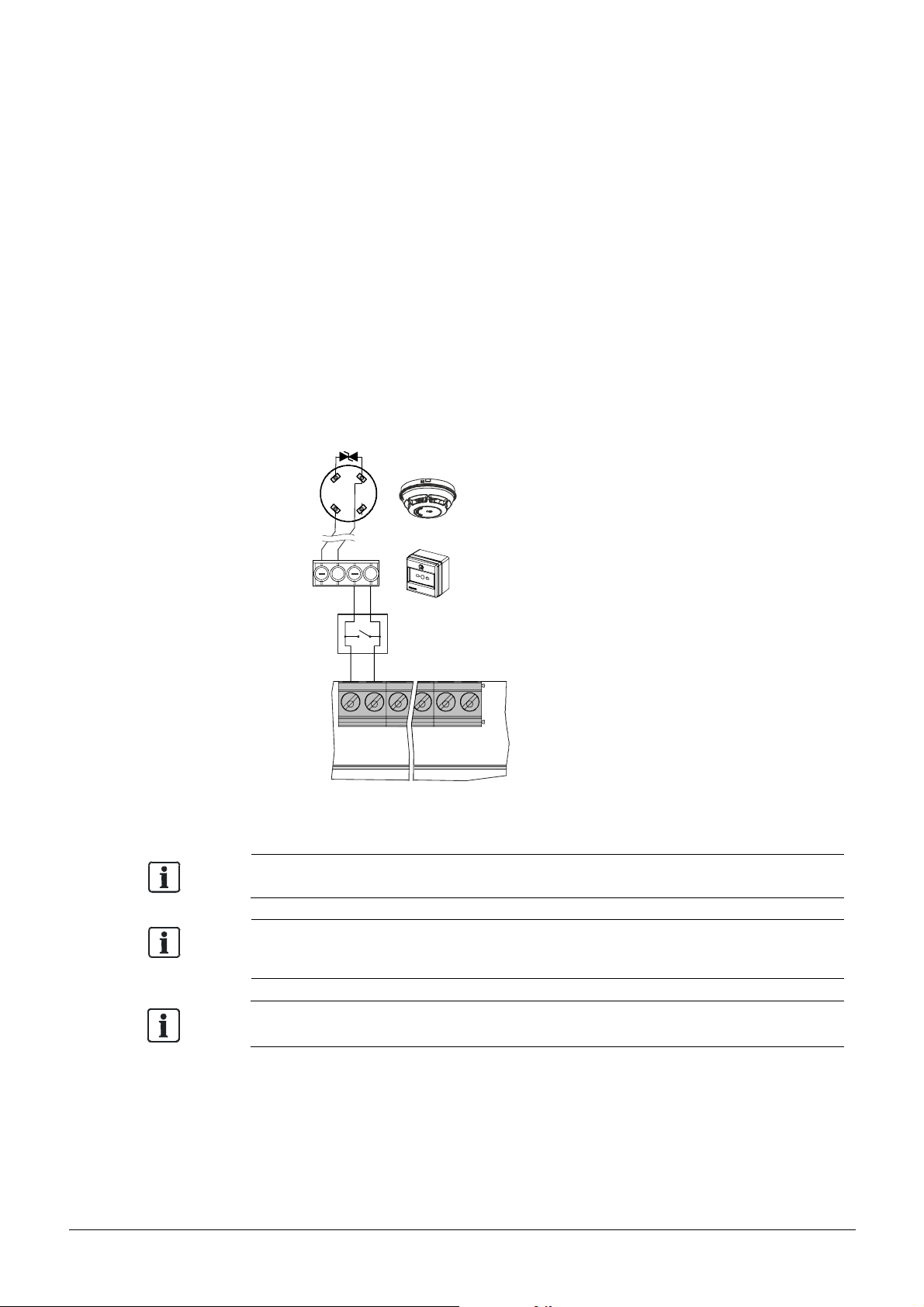
4.3.3 GB continuity
EOL
The GB continuity line allows a mixture of MCPs and detectors within the same zone.
In addition this mode supports a reliable operation, even though one or more detectors
are removed from its base. The CIE detect the removed detector and report a zone fault.
Technical:
- Special detector bases equipped with a diode (1N5819):
DB110D part number S54372-F6-A1 or DB110RD part number S54372-F8-A1
- MCPs require a Z-diode for direct alarming (AVC).
- Siemens detectors 110-series or detectors with an alarm resistor are required for
delayed alarming (AVC, V1 / V2).
- Each line must be terminated with EOL element Capacitor 10 µF.
- Limitation: Max. 18 detectors per line is allowed due to voltage drop on the detector
base.
- MCPs have no limitation and can be installed to reach the maximum of 32 devices.
Programming:
- Configure g Zone g Zone 1 – n g Mode g GB continuity
- Configure g Zone g Zone 1 – n g AVC g Via AVC timer MCP direct
6
1
b
1
5
ZONE1
a
+
+
–
+
NOTICE
See details of the specification in chapter 3.3.1.
Zone mode ‘GB continuity’ does NOT comply with EN 54-13.
Behavior of MCP in zone coincidence with function 'direct alarming' is not supported.
24
Smart Infrastructure A6V10393190_h_en_--
2019-09-01
Page 25
4.3.4 Short = alarm
Even if a zone
is switched off, a short
is evaluated as an alarm.
ZONE1
. . . . . .
EOL
This line supports a mixture of detectors and MCPs within the same zone.
In addition, this line supports devices with a closed contact for alarm.
Only automatic fire detectors can be switched off. Manual call points with the alarm
criterion 'Short = Alarm' are always switched on and cannot be switched off.
Technical:
- Short in the line is detected as an alarm and not as a fault.
- Max.32 devices on each line.
- Each line must be terminated with EOL element Transzorb diode (18 V TVS).
- Does not fulfill EN 54-2.
Programming:
- Configure g Zone g Zone 1-n g Mode g Short = alarm
6
b
1
a
1
5
+
+
–
–
+
+
–
+
ZONE n
Zone mode 'Short = alarm' does NOT comply with EN 54-2 and EN 54-13.
Special detectors FDOOT241-9, OOH740, FDF221-9, FDF241-9, FDL241-9 NOT
compatible with the zone mode 'Short = alarm'.
Smart Infrastructure A6V10393190_h_en_--
25
2019-09-01
Page 26

4.4 Outputs
OUTA
OUTB
OUTC
OUTD
EOL
EOL
COM
COM
Outputs are used to transmit system status information. As a result three different types
are available: Monitored, Supervised and Relay.
–
+
–
OUT1
Monitored
+
–
+
OUT2
COM NO
OUT3
Relay
–
Monitored or
Supervised
Mainboard
4.4.1 Mainboard (OUT1 / OUT2)
Functionality 'Monitored line':
The panel monitors the line in terms of open and short circuits from the panel to the
EOL element.
Application:
Sounder controls, fire outputs and dialer
Technical:
- Max. current
FC121-ZA and FC122-ZA à 24 V / 0.5 A
FC123-ZA and FC124-ZA à 24 V / 1 A
- Each line must be terminated with EOL element (Diode 1N4007)
- Supervised functionality: Not available
–
+
+
NONC
NONC
Relay
Output card
Programming:
- Configure g Output g Output 1 – n g Mode g Sounder control
4.4.2 Output card (OUTA / OUTB)
The output can be either programmed as 'Monitored' or 'Supervised'.
Functionality 'Monitored line':
The panel monitors the line in terms of open and short circuits from the panel to the
EOL element.
Application:
Sounder controls, fire outputs and dialer
Technical:
- Max. current 24 V / 1 A
- Each line must be terminated with EOL element (Diode 1N4007)
Programming:
- Configure g Output g Output 4 – n g Mode g Sounder control
26
Smart Infrastructure A6V10393190_h_en_--
2019-09-01
Page 27
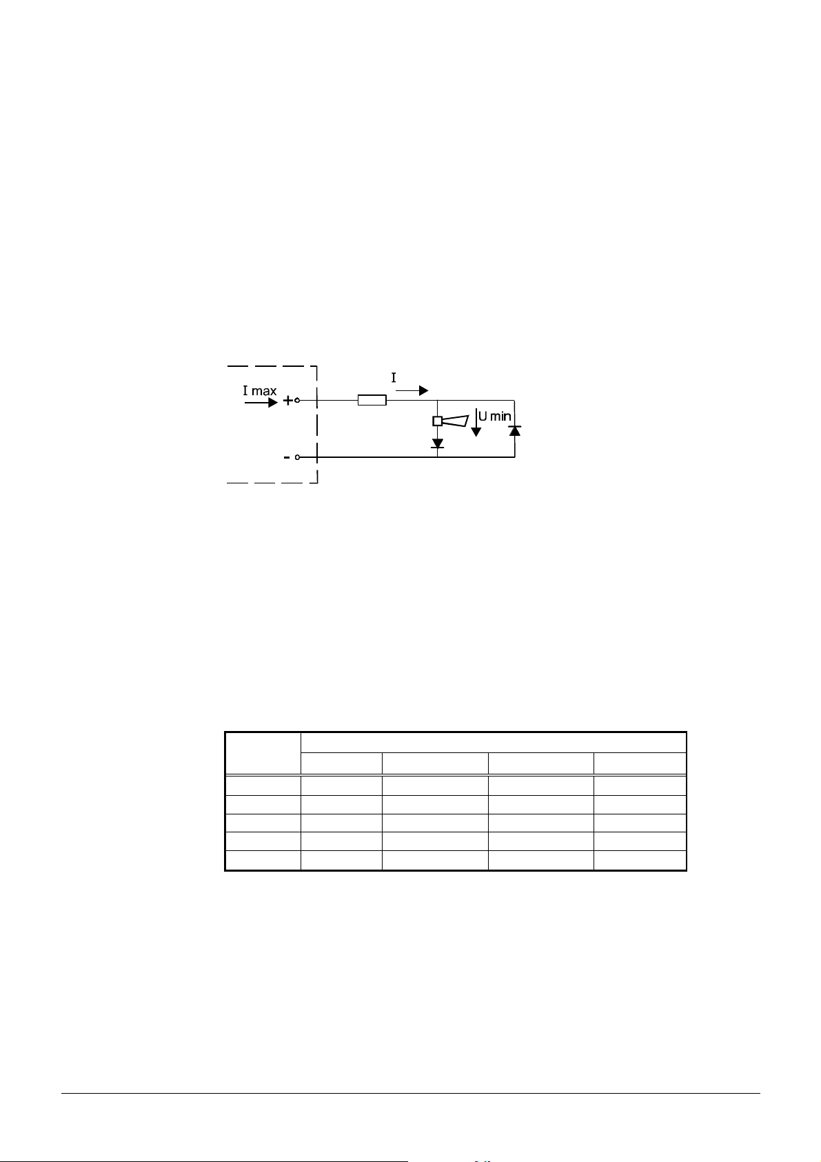
Functionality 'Supervised line':
max
min
min
min
min
OUT A
The panel monitors the line in terms of open and short circuits from the panel to the
EOL element.
In addition to the line monitoring, the panel will recognize a change of line resistance.
Due to aging or other circumstances (creeping effect), the transition resistance on
contacts may increase, which in turn leads to voltage drop.
In order to detect the creeping effect (supervision), the line must be calibrated during the
commissioning process. A line fault is indicated if the resistance is higher than 35 Ω.
Checking the line resistance depending on the required current
It is calculated that the supply of the connected devices is met.
The picture shows the dependence of the line resistance (R Line) in relation to the device
voltage (U
) and the available output current (I
min
) and the minimum required current of
max
the connected devices (I Load).
R Line
Load
EOL
Procedure for determining the maximum available device current (I Load):
1) Determine the line resistance R Line.
Programming: see chapter 7.2.1 (Calibration)
Configure à Output à Output 4 – n à Calibrate line
2) Detecting the voltage U
according to the device datasheet.
min
3) Verification: Are all parameters satisfied for the correct operations?
Table 1 can be used for this check, here are maximum values shown.
Details are individual to calculate.
Table 1
R Line
U
I
= 9 V U
= 14.5 V U
= 16.8 V U
= 18 V
1 A 0 ~ 7 Ω 0 ~ 3.5 Ω 0 ~ 2 Ω 0 ~ 1 Ω
0.5 A 0 ~ 14.5 Ω 0 ~ 7.5 Ω 0 ~ 4.5 Ω 0 ~ 3 Ω
0.3 A 0 ~ 25 Ω 0 ~ 13 Ω 0 ~ 8 Ω 0 ~ 5.5 Ω
0.1 A 0 ~ 35 Ω 0 ~ 35 Ω 0 ~ 26 Ω 0 ~ 18.5 Ω
0.05 A 0 ~ 35 Ω 0 ~ 35 Ω 0 ~ 35 Ω 0 ~ 35 Ω
Counteractive measures: Reduction of I Load or of R Line.
Functionality 'Supervised line for fault dialer and relay':
The line is supervised, from the terminal including the activated relay in the fault dialer, in
terms of open and short circuit. In addition to the line supervising, the panel will recognize
a change of line resistance. Due to aging or other circumstances (creeping effect), the
transition resistance on contacts may increase, which in turn leads to voltage drop.
27
Smart Infrastructure A6V10393190_h_en_--
2019-09-01
Page 28

In order to detect the creeping effect (supervision), the line must be calibrated during the
commissioning process. A line fault is indicated if the resistance is higher than calibrated.
The range of the line resistance including the relay is between 200-1000 Ω.
Application:
With EOL diode: Sounder controls, fire outputs and alarm dialer.
With monitored relay for fault dialer: Only OUT A is specified to supervise the device
relay, see details in chapter 4.4.4.
Technical:
- Max. current 24 V / 1 A
- Line resistance max. 35 Ω
- Each line must be terminated with EOL element (Diode 1N4007)
Programming:
- Configure g Output g Output 4 – n g Mode g e.g. Sounder control
- Configure g Output g Output 4 – n g Supervision EN 54-13
- Configure g Output g Output 4 – n g Calibrate line
4.4.3 Relay
Relay outputs are used for controls without line monitoring.
Application:
LED indication on a remote terminal
Technical:
- Max. current 30 V / 1 A
Programming:
- Configure g Output g Output 6 – n g Mode g Fire output
28
Smart Infrastructure A6V10393190_h_en_--
2019-09-01
Page 29

4.4.4 Dialer connection
O
U
T
3
C
O
M
N
O
+
+
_
X
.
2
4
+
+
_
O
U
T
A
+
_
C
O
M
N
O
+
200 1000
Ω ~ Ω
FC12x
Dialer
FC12x
Dialer
The FC12x fire control panel provides 'monitored' and 'supervised' dialer connections:
Application 1
- 'Alarm dialer' output (OUT2) monitors the line to the dialer.
- 'Fault dialer' output (OUT3) has no line monitoring to the dialer.
(Does not fulfill chapter 8.9 in EN 54-2)
Programming:
- Configure g Outputs g Output 2 g Alarm dialer g
Activation condition 'General Alarm'
- Configure g Outputs g Output 3 g Fault dialer g Activation condition 'Any fault'
Application 2
- 'Alarm dialer' output (OUTB) supervises the line to the dialer.
- 'Fault dialer' output (OUTA) supervises the line and the build in relay of the dialer.
The relay takes over EOL element functionality, if the resistance is between 2001000 Ω.
Programming:
- Configure g Outputs g Output 5 g Alarm dialer g
Supervision EN 54-13 / Calibrate line / Activation condition 'General Alarm'
- Configure g Outputs g Output 4 g Fault dialer g
Supervision EN 54-13 / Calibrate line / Activation condition 'Any fault'
_
X.24
+
INPUT 1*
_
+
AU
INPUT 1*
_
_
+
(1)
OU
OUT2
_
+
Application 1 Application 2
(1) Dialer device confirmation signal
As an option, the panel can receive the dialer activation if desired.
The output 'fault dialer' is closed (Inverse function) in quiescent mode.
In case of fault, the output opens.
_
T B
+
29
Smart Infrastructure A6V10393190_h_en_--
2019-09-01
Page 30

4.5 Input
INPUT
The programmable input function allows control of the panel by a third-party system.
Programming:
- Configure g Input g Input 1-n g Mode g e. g. Class change signal
–
+
AUX 24V
Third-party system
1 2 3
30
Smart Infrastructure A6V10393190_h_en_--
2019-09-01
Page 31

4.6 Accessories
X40
X10
X30
X20
X50
X10
X40
X30
X20
Connect the accessories as shown.
FC121-ZA / FC122-ZA
Terminals Accessories
X50 not used
X40
FTO1201-H1 EVAC Module (NL 2&4 Z)
FTO1203-H1 EVAC Module (NL 8&12 Z)
FTO1202-Z1 Zone ind. field 12x2LED
X30 FCA1203-Z1 Output card 2M 2R
X20 FCA1206-Z1 Key switch set (Nordic SE)
X10 FDUZ221 MCL-USB adapter
FDUZ227 MCL-USB adapter (radio)
4.6.1 Key switch set
The key switch set is available for the following panels.
FC121-ZA FC122-ZA FC123-ZA FC124-ZA
FCA1206-Z1
FC123-ZA / FC124-ZA
þ þ þ þ
FCA1206-Z1
Example FC124-ZA
Function:
The key switch enables 'access level 2' (see chapter 6.4) without password.
Programming:
- No programming is required.
31
Smart Infrastructure A6V10393190_h_en_--
2019-09-01
Page 32

4.6.2 Output card
2
EOL
EOL
Earth con
n
ection
(only used for FCA1203
-
Z1)
The output card is available for the following panels.
Output card Mounting slot FC121-ZA FC122-ZA FC123-ZA FC124-ZA
FCA1203-Z1
Example FC124-ZA
①
þ þ þ þ
② þ þ
③
þ
FCA1203-Z1
1
3
FC121-ZA / FC122-ZA
Function:
Each output card provides four outputs and one power input 24 V for external powering
of the outputs A and B. Check power calculation in chapter 11 whether you have to
power those outputs internally or externally.
Internal:
By default, output A and B are supplied by the internal PSU.
External:
Connect the wires from an external PSU to the terminal '24V In'.
The output card switches automatically from internal to external supply.
Programming:
- Output cards are automatically enabled if plugged in before initial start-up.
Output:
The output numbers include a reference to the respective output cards:
Mounting
slot
Outputs for programming
A B C D
① 4 5 6 7
② 8 9 10 11
32
Smart Infrastructure A6V10393190_h_en_--
③ 12 13 14 15
2019-09-01
Page 33

4.6.3 EVAC module (NL)
FTO1203-H1
The EVAC module is available for the following panels.
EVAC Module (NL) FC121-ZA FC122-ZA FC123-ZA FC124-ZA
FTO1201-H1
FTO1203-H1
FC121-ZA / FC122-ZA
Function:
The EVAC module NL provides the Dutch special function.
All sounder controls are changed to EVAC sounder NL.
Mounting module before initial start-up:
- If the module is connected before the initial start-up, the NL presetting and language
is pre-selected automatically.
- The functionality and EVAC sounder NL are available if the pre-selected setting is used.
þ þ
þ þ
FTO1201-H1
FC123-ZA / FC124-ZA
Mounting module after initial start-up:
- Enable the EVAC module in the programming.
- Change all programmed sounder outputs to EVAC sounder NL.
Programming: Configure g Accessory g EVAC module
Configure g Output g Output n g Mode g EVAC Sounder NL
Operating:
All programmed outputs to 'EVAC Sounder NL' are activated by pressing the start
button twice.
1
3
4
2
No. Description Status Function
1 LED: EVAC zone active ON Evacuation is activated.
2 LED: EVAC fault Flashing Fault on the EVAC sounder lines(s) has occurred.
3 Button: START Press twice to start the evacuation.
4 Button: STOP Press twice to stop the evacuation.
33
Smart Infrastructure A6V10393190_h_en_--
2019-09-01
Page 34

4.6.4 Zone indication field
The zone ind. field FTO1202-Z1 as shown in the graphic below.
FC121-ZA FC122-ZA FC123-ZA FC124-ZA
FTO1202-Z1
þ þ
Example FC124-ZA
Function:
The zone ind. field shows the actual status of each zone.
- LEDs are fixed assigned and cannot be changed.
Programming:
FTO1202-Z1
- No programming is needed.
1
2
3
No. Description Status Function
1 Zone alarm
(Red)
2 Zone fault
(Yellow)
ON The zone is in alarm state.
Flashing The zone is in first alarm state.
ON The zone is disabled.
Flashing Zone is in fault.
3 Inscribable fields Inscription of zone number and customer text.
34
Smart Infrastructure A6V10393190_h_en_--
2019-09-01
Page 35

4.7 Initial start-up
The initial start-up is required with every new installation.
4.7.1 Prepare the panel
Make sure that the installation instructions, steps 1-8 are fulfilled (chapter 4.2)
and all accessories are connected (chapter 4.6).
1) Switch on the mains supply.
N
2) Connect the battery.
L
Red (+)
Black (-)
Smart Infrastructure A6V10393190_h_en_--
2019-09-01
35
Page 36

4.7.2 Pre configuration
ok
ok
p
q
After the panel is powered up, the following display is shown.
Country settings
Presetting t Factory setting u
Language t English u
Country settings
Presetting t Factory setting u
Language t English u
Country settings
Presetting < UK >
Panel
Language < English >
will restart!
p
t
t
u
q
p
u
t
Change country setting by the navigation key
<u>.
Move to the second line with <q> and
u
select the appropriate Language with <u>.
q
Confirm the entry by the <ok> button.
The panel will restart with the country specific
presetting.
Set date & time
01.01.2000 00:00
Set date & time
22.12.2012 08:08
p
t
u
p
Change the first value ‘day’ with <p> / <q>
t
u
and move to the next with <u> and so on.
q
q
Confirm the entry by the <ok> button.
The system is now ready for individual
programming (see chapter 7).
Relevant to NL with EVAC module only:
If the EVAC module is mounted, the country setting is automatically selected by the
system.
36
Smart Infrastructure A6V10393190_h_en_--
2019-09-01
Page 37

5 Function overview
5.1 Operating functions
The operating functions are related to the following topics.
Alarm Disable / Enable System test
- Acknowledge
- Reset
- Silence sounder
- Manned / unmanned
- Cancel alarm delay
5.2 Access levels
The FC12x provides four different access levels.
Access
level
1 No need End user to view pending events.
2 5555
3 6666 Commissioning personnel:
Password Function
or
key switch
- Zone
- Sounder control
- Fire output
- Alarm dialer
- Fault dialer
Instructed and authorized end user:
- Switch on / off zones and outputs.
- Automatic logout after 2 minutes of no operation.
- Password is not necessary if a key switch is used.
- System programming.
- Automatic logout after 10 minutes of no operation.
- The basic function of panel will not continue.
- Mode walk test with
sounder activation for
1 second
- LED test
4 6666
and front
cover open
6669 - Reset alarm counter.
Smart Infrastructure A6V10393190_h_en_--
Commissioning personnel:
- Save and restore site configuration.
- Upload history log.
- Update firmware.
2019-09-01
37
Page 38

5.3 LED indication
put
The following LED indications are available:
1
2
3
4
5
6
q
7
No. Description Colour Status Function
1 Alarm Red ON The fire control panel is in 'Alarm' condition.
2 Acknowledge Yellow Slow Indicates where action is expected.
3 More alarm Red Slow More than two zones have triggered a fire alarm.
4 Reset Yellow Slow Indicates the action in case of an alarm or fault.
5 Fire brigade Red ON Depending on the programming mode.
6 System on Green ON The system is in operation.
7 General fault Yellow ON Indicates any fault in the system.
8 System fault Yellow ON Indicates CPU failure.
9 Sounder fault Yellow ON Sounder lines are disabled.
10 Alarm dialer fault Yellow ON Alarm dialer output is disabled.
8
9 10
Option 1: Call the fire brigade, panel is in alarm mode.
Option 2: Call the fire brigade, output Alarm dialer is active.
Option 3: Fire brigade is called.
Slow Sounder line is in fault state.
Slow Alarm dialer output is in fault state.
11 12
13 14 15
11 Test condition Yellow ON At least one zone is in test state.
12 Isolation Yellow ON At least one zone or output is disabled.
13 Manned / Unmanned Yellow ON Manned operation (AVC).
OFF Unmanned operation (AVC).
Fast 2 Hz Reaction time V1 is running (AVC).
Slow 1 Hz Investigation time V2 is running (AVC).
14 Resound Red ON Sounder lines are activated.
15 Silence Yellow ON Sounder lines are silenced.
38
Smart Infrastructure A6V10393190_h_en_--
2019-09-01
Page 39

5.4 Buttons
▲►▼
◄
The following buttons are available:
11
10
9
8
7
6
5
1 432
No. Description Function
1 MORE ALARM Move to the next 'fire alarm'.
2 RESET Reset the fire control panel to quiescent condition.
· Starts the investigation time V2 (AVC).
3 ACKNOWLEDGE
· Silence the buzzer until a new alarm event occurs.
· Silence the sounder until a new event occurs (if programmed).
4 SILENCE BUZZER Silence the buzzer until a new event (alarm, alert or fault) occurs.
5 SILENCE
RESOUND
· Silence the sounder control(s) in the event of alarm.
· Manually re-activate the sounder control(s) during alarming.
· If programmed, activation of all sounder control(s)
(activation mode only in quiescent condition).
MANNED /
6
UNMANNED
· Switch between manned / unmanned.
· Cancel the alarm delay V1 / V2 when V1 / V2 is running.
7 LAMP TEST Activate all LEDs, the buzzer and the display on the PMI.
8 CANCEL Move one step back without saving the change.
9 OK Confirm the selected value.
10 MENU Enter the main menu.
· Select the menu or change the time: <p> and <q>.
11 NAVIGATION
· Change the selection: <t> and <u>.
· Change to the next level or select value in the checkbox: <u>.
Smart Infrastructure A6V10393190_h_en_--
2019-09-01
39
Page 40

5.5 Display
ok
????
The display is divided into 4 sections.
1
Menu 2:00
Actual events u ▲
Enable / disable u
2
History log u
Set date & time u
Login u
Logout u ▼
1: Title
This line displays the main menu.
2: Window
This window displays the sub menus and its parameters.
3: AVC timer or access level
- Countdown of the AVC timer V1 and V2
- Indication of the access level
4: Scrollbar
Scrollbar is provided if more information is visible in a second window.
5.6 Password entry
3
4
How to get access to the fire control panel.
Login 1
1 2 3
4 5 6
7 8 9
0
Access levels according to chapter 5.2.
l Select the 1st number of the password by
the navigation button and confirm with <ok>.
p
ut
q
l Repeat until the last '?' is replaced.
l If the password is correct, the respective
access level is granted.
40
Smart Infrastructure A6V10393190_h_en_--
2019-09-01
Page 41

6 Operation
6.1 General fire alarm procedure
In case of a fire alarm, the following indication is shown on the panel:
· The fire alarm is indicated by the LEDs (1).
· The first and last alarm zone are displayed (8).
· Further fire alarms are indicated by the flashing LED (2). In order to move to the
next alarm event, press the button (4).
· The internal panel buzzer indicates a fire condition acoustically. As an option,
the buzzer can be silenced by pressing the button (7). A new alarm event will
reactivate the buzzer again.
· Output alarm dialer is activated when LED (3) is ON. (Call the fire brigade.)
· Programmed system outputs, including connected audible and visual
notification appliances, get activated.
· The flashing acknowledge LED (5) indicates the possible action to acknowledge
by pressing the button (6).
Smart Infrastructure A6V10393190_h_en_--
2019-09-01
41
Page 42

6.1.1 Procedure without Alarm verification
The Alarm dialer is activated in the event of a fire alarm.
Fire alarm 1
Zone 1 1/1
Meeting room 1
MAJOR INCIDENT: A real fire emergency
Fire alarm 1
Zone 1 1/1
Meeting room 1
MINOR INCIDENT: No fire alarm
Press the <ACKNOWLEDGE> button.
If the alarm event is acknowledged, the panel
turns off the panel buzzer.
è Access level 2 password is required.
Optional: Silence the sounder lines by pressing
<RESOUND / SILENCE> button.
Check if the fire brigade called.
Normal Operation
Siemens FC12X
22.12.2012 08:08
1
Reset the system to quiescent mode by pressing
<RESET> button.
è Access level 2 password is required.
Inform the fire brigade about the actual situation.
Notice
The fire alarm reoccurs if any device remains in fire condition.
42
Smart Infrastructure A6V10393190_h_en_--
2019-09-01
Page 43

6.1.2 Alarm Verification Concept (AVC)
Unmanned
State
'ALERT
”
unmanned:
unmanned:
The graphic below illustrates the difference between the AVC and the DIRECT alarm
procedure. The AVC concept takes the interaction of personnel into consideration.
AVC DIRECT
Manned
· Buzzer activated
· Sounder output activated if programmed
· Reaction time 'V1” has started
No
Yes
Fire?
Manned/
V1 time out
State 'ALARM'
· Buzzer (re-)activated
· Sounder output (re-)activated
Manned operation
Manned operation enables the responsible personnel to examine the fire alarm before
initiating the intervention force. This may avoid hassles in case of false alarms.
Reaction time (V1)
In case of a fire incident, the responsible personnel must confirm the alert at the fire
control panel by pressing the acknowledge button (ACK).
Investigation time V2 starts if activated. If nobody confirms the alert state, the V1 timer
expires and the panel automatically goes to 'ALARM' state.
In the event of a major incident (emergency), the nearest ‘Manual call point’
or <Manned/Unmanned> button must be pressed to turn the fire control panel into
'ALARM' state. (1function depends on programming)
Ack:
No
Yes à V2 start
No
Fire?
Reset: Manned/
V2 time out
Yes
· Fire output activated
· Alarm dialer activated (Intervention)
1
Investigation time (V2)
During the investigation time V2 the operating personnel may examine the location of
fire:
In the event of a major incident (emergency), the nearest ‘Manual call point’
2
or <Manned/Unmanned> button must be pressed to turn the fire control panel into
'ALARM' state. (2function depends on programming)
The panel goes to 'ALARM' state if the investigation is not confirmed within time V2.
The operator may reset the panel in the case of a minor incident or false alarm.
Smart Infrastructure A6V10393190_h_en_--
2019-09-01
43
Page 44

6.1.3 Procedure with Alarm Verification
In the event of a fire alarm, the reaction timer V1 gets started.
Fire alarm 2:00
Zone 1 1/1
Meeting room 1
Fire alarm 3:00
Zone 1 1/1
Meeting room 1
Action is requested
During the investigation time, examine the location of the fire and decide whether it is
a MAJOR INCIDENT or MINOR INCIDENT.
MAJOR INCIDENT: A real fire emergency
V1
V2
Press the <ACKNOWLEDGE> button to confirm
the attendance. If the alarm event is
acknowledged, the buzzer turns off.
è Access level 2 password is required.
The investigation timer V2 is started.
Optional:
Silence the sounder by pressing <RESOUND /
SILENCE> button.
Fire alarm 2:00
Zone 1 1/1
Meeting room 1
MINOR INCIDENT: No fire alarm
Normal Operation
Siemens FC12X
22.12.2012 08:08
Notice
The fire alarm reoccurs if any device remains in fire condition.
Cancel the investigation time by pressing the
<MANNED / UNMANNED> button.
è Access level 2 password is required.
Reset the system to normal operation by pressing
<RESET> button.
è Access level 2 password is required.
44
Smart Infrastructure A6V10393190_h_en_--
2019-09-01
Page 45

6.2 Fault procedure
A list of possible '
Faults
' can be found in
chapter
12
.
In the event of a fault, the panel displays the fault.
As an option, programmed outputs can be activated (e.g. fault dialer).
Fault 1
Battery 1/2
Zone 1 2/2
Action is requested.
Solve the cause of the fault.
Press the <SILENCE BUZZER> button.
Buzzer is turned off.
Normal Operation
Siemens FC12X
22.12.2012 08:08
Acknowledge and reset the system to normal
operation by pressing the <ACKNOWLEDGE>
and <RESET> button.
è Access level 2 password is required.
Notice
The fault reoccurs if acknowledged but not resolved.
Smart Infrastructure A6V10393190_h_en_--
45
2019-09-01
Page 46

6.3 Access level 1
C
ok
p
ok
tpq
t
Operation is available without password.
6.3.1 Actual events
The actual events will display all pending events.
Menu 1
Actual events u
Login u
Alarm counter 0001
Actual events 1
Fire alarm u 0
Fault u 2
Isolation u 0
Test u 0
Information u 0
Push button <MENU>.
u
Select ‘Actual events’ with navigation button and
confirm with <ok>.
t
u
The left picture shows the 5 entry points.
Select one event type and confirm with <ok>.
q
Fault 1
Battery 1/2
Output 1 2/2
①
p
t
u
q
The details are visible with the number of events
indicated for the category.
e.g. two events exist in this category.
Go back to the main menu with <C>.
46
Smart Infrastructure A6V10393190_h_en_--
2019-09-01
Page 47

6.3.2 Login
C
ok
**
??
ok
t
The panel is protected against unauthorized user operation.
Therefore enter the password or turn the key switch (optional).
Menu 1
Actual events u
Login u
Alarm counter 0001
Push button <MENU>.
p
t
u
q
Select ‘Login’ and confirm with <ok>.
Login 1(#)
1 2 3
4 5 6
7 8 9
0
6.3.3 Alarm counter
The alarm counter counts all fire alarms.
Menu 1
Actual events u
Login u
Alarm counter 0001
l Select the digit using the navigation button
p
ut
q
and confirm it with <ok>.
l The ‘?’ is replaced by ‘*’ with every entered
digit.
l Press <C> to cancel the input.
(#) shows the actual access level.
t
Push button <MENU>.
The number of counted alarms is shown.
Exit with <C>.
47
Smart Infrastructure A6V10393190_h_en_--
2019-09-01
Page 48

6.4 Access level 2
Operation is available with password or key switch.
6.4.1 Manned / unmanned
In case of attendance switch the fire control panel to manned operation.
Information 2
Manned operation 1/1
Manned mode
activated
6.4.2 Silence / resound
Sounders are activated in the event of a fire alarm.
Press the <MANNNED / UNMANNED> button to
toggle.
Manned mode – LED ON
Unmanned mode – LED OFF
Press the <SILENCE / RESOUND> button to
silence the sounders.
It is possible to reactivate the sounders in the
event of a fire alarm at any time.
Every new alarm event will reactivate the
sounders again, if programmed.
Optional: The sounders can be activated at any
time 'Toggle function' (no alarm event is required)
if programmed.
6.4.3 LED, display and buzzer test
Test the panel indication.
Press the button <LAMP TEST> and all LEDs, the
display and the internal buzzer are activated for a
period of 5 seconds.
48
Smart Infrastructure A6V10393190_h_en_--
2019-09-01
Page 49

6.4.4 Display history log
ok
tpq
C
p
ok
p
Logout
u
t
All events such as alarm(s), fault(s), isolation(s), input(s) and output(s) activation are
stored in a history log.
Menu 2
Actual events u
Enable / disable u
History log u
Set date & time u
Login u
History log 2
Fault 1/2
Set date & time
10.08.2012 12:18
Push button <MENU>.
t
u
q
Select ‘History log’ and confirm with <ok>.
All events are visible.
t
u
q
Fast scrolling is possible by holding <p> / <q>
navigation button.
6.4.5 Logout
Manual logout to access level 1.
Panel automatically logs out if no action is taken within 2 minutes.
Menu 2
Actual events u
Enable / disable u
History log u
Set date & time u
Login u
Logout u
Successful
Go back to the main menu with <C>.
t
u
1
Push button <MENU>.
Select ‘Logout’ and confirm with <ok>.
The panel is logged out successfully to previous
access level.
49
Smart Infrastructure A6V10393190_h_en_--
2019-09-01
Page 50

6.4.6 Set date and time
ok
qut
ok
t
p
q
Push button <MENU>.
Menu 2
Actual events u
Enable / disable u
History log u
Set date & time u
Login u
Logout u
Set date & time
01.01.2000 00:00
Set date & time
22.12.2012 08:08
p
t
t
u
q
p
u
Select ‘Set date & time’ and confirm with <ok>.
Change the first value with <p> / <q> and
move to the next with <u> and so on.
Confirm with <ok>.
50
Smart Infrastructure A6V10393190_h_en_--
2019-09-01
Page 51

6.4.7 Enable / disable zone
C
Zone
6tOn
u
ok
p
Zone
6tOn
u
ok
p
ok
Each zone can be isolated individually.
Menu 2
Actual eventsu
Enable / disable u
History log u
Set date & time u
Login u
Logout u
Enable / disable 2
Zone u
Sounder t On u
outputs
Fault t On u
dialer
Enable / disable 2
Zone 1 t On u
Zone 2 t Off u
Zone 3 t Off u
Zone 4 t On u
Zone 5 t On u
t
p
t
t
t
u
q
u
q
p
u
t
q
q
Push button <MENU>.
Select ‘Enable / disable’ and confirm with <ok>.
Select ‘Zone’ and confirm with <ok>.
Select a zone and change its property with <u>.
u
Change zone properties for other zones as
needed.
Isolation 2
Successful
Zone 6 t On u
Enable / disable 2
Zone 1 t On u
Zone 2 t Off u
ok save and exit
Zone 3 t Off u
C exit without
Zone 4 t On u
saving
Zone 5 t On u
Confirm all changes with <ok>.
Exit menu without change by pressing the button
<C> for the first time and then a second time
while the information is displayed.
51
Smart Infrastructure A6V10393190_h_en_--
2019-09-01
Page 52

6.4.8 Enable test mode
Enable the test mode for each zone
.
C
Zone
6tOn
u
ok
Zone
6tOn
u
p
q
q
Zone
6tOn
u
ok
ok
t
Menu 2
Actual eventsu
Enable / disable u
History log u
Set date & time u
Login u
Logout u
Enable / disable 2
Zone u
Sounder t On u
outputs
Fault t On u
dialer
Push button <MENU>.
p
t
u
q
Select ‘Enable / disable’ and confirm with <ok>.
Select ‘Zone’ and confirm with <ok>.
Enable / disable 2
Zone 1 t Test u
Zone 2 t On u
Zone 3 t On u
Zone 4 t On u
Zone 5 t On u
Enable / disable 2
Successful
Zone 1 t On u
Zone 2 t Off u
Zone 3 t Off u
Zone 4 t On u
Zone 5 t On u
Enable / disable 2
Zone 1 t On u
Zone 2 t Off u
ok save and exit
Zone 3 t Off u
C exit without
Zone 4 t On u
saving
Zone 5 t On u
p
u
t
t
Select a zone and change its property with <u>.
u
Change zone properties for other zones as
needed.
Confirm all changes with <ok>.
Exit menu without change by pressing the
button <C> for the first time and then a second
time while the information is displayed.
52
Smart Infrastructure A6V10393190_h_en_--
2019-09-01
Page 53

6.4.9 Enable / disable outputs
C
ok
p
Output
6tOn
u
ok
ok
Disable outputs generally and / or individually.
Menu 2
Actual eventsu
Enable / disable u
History log u
Set date & time u
Login u
Logout u
Enable / disable 2
Zone u
Sounder t On u
outputs
Fault t On u
dialer
Enable / disable 2
Output 1 t Off u
Output 2 t On u
Output 3 t On u
Output 4 t On u
Output 5 t On u
t
p
t
t
u
q
p
u
Push button <MENU>.
Select ‘Enable / disable’ and confirm with <ok>.
Select the respective Output (e.g. ‘Fire
outputs‘) and confirm with <ok>.
q
p
u
t
q
t
q
Select an output and change its property with
<u>.
u
Change output properties for other outputs as
needed.
Fire output 2
Output 1 t On u
Successful
Fire output 2
Output 1 t On u
ok save and exit
C exit without
saving
Confirm all changes with <ok>.
Exit menu without change by pressing the
button <C> for the first time and then a second
time while the information is displayed.
53
Smart Infrastructure A6V10393190_h_en_--
2019-09-01
Page 54

6.4.10 Panel information
C
ok
t
C
Output card
3
u
ok
p
t
Information about the software is displayed.
Menu 2
Panel informationu
Alarm counter 0001
Service information u
Panel information 2
Type: FC124-ZA
App: 01.00.19
Boot: 01.00.04
Output card 1u
Output card 2 u
Push button <MENU>.
t
u
q
Select ‘Panel information’ and confirm with <ok>.
Exit with <C>.
6.4.11 Service information
The service information is shown in quiescent mode (e.g. contact address of the service
provider and panel information).
Menu 2
Panel informationu
Alarm counter 1
Service information u
Service information 2
xxxxxx FC12X
xxxxxxu
Push button <MENU>.
p
t
u
q
Select ‘Panel information’ and confirm with
<ok>.
Exit with <C>.
54
Smart Infrastructure A6V10393190_h_en_--
2019-09-01
Page 55

Configure
7 Programming
For programming, access level 3 is required.
All outputs are automatically isolated during programming mode.
All disabled outputs are automatically enabled if access level 2 is reached.
7.1 Configure
Zone
Zone 1..n
Mode
7.1.1 Zone
Configure parameter for each zone.
Select a zone for programming.
Standard
Mixed MCP & det.
GB continuity
Short = alarm
Automatic detectors
and manual call
points can be mixed
within the same
zone.
Device could be
either conventional
or collective.
InputOutputZone
AVC option
'1', '2'
AVC option
'1', '2', '3'
Accessory
card(s)
If detectors are removed, the
zone will work properly.
Any short is detected as 'Fire
Alarm'.
AVC
*Device
coincidence
Zone
coincidence
Customer
text
Smart Infrastructure A6V10393190_h_en_--
Direct
Via V1 / V2
Via AVC timer
MCP direct
If selected, the 'Alarm' state is achieved, if the second device activation in the same zone
occurs within 90 seconds. The first device activation is inhibited from the zone and
automatically reset after a defined time, (default value: 15 second, see chapter 7.2.5).
If selected, the 'Alarm' state is achieved, if the second corresponding zone is in 'Alarm' as well.
The zone pairs (1&2, 3&4, 5&6, etc) are predefined in the system,
e.g. if zone 6 is selected, zone 5 is automatically linked as well and vice versa.
Name the zone, see chapter 7.5.
*Do NOT use this function in combination with FDOOT241-9 (ES<13). For detailed
information refer to document A6V10393192.
No delay, immediate alarm.
'1'
'2' Delayed alarm. V1: reaction time, 3 min.
- Delayed alarm for automatic
'3'
detectors.
- No delay for MCPs.
V2: investigation time, 5 min.
(Change value, see
chapter 7.2.10).
2019-09-01
55
Page 56

7.1.2 Output
upervision
1..n
Output
Output
Mode
S
EN 54-13
Configure the output parameters.
Select an output for programming.
Sounder control Sounder control is used to activate sounder lines.
(EVAC module replaces 'sounder control' with 'EVAC sounder NL'.)
Alarm dialer
Alarm dialer is used to transmit the fire alarm to the intervention
force, e.g. fire brigade.
Fault dialer
Fault dialer is used to transmit the fault signal to the intervention
force, e.g. service provider.
Fire output
Fire outputs are used to activate / deactivate controls,
e.g. door holders, lifts, air-condition, etc.
EVAC Sounder NL
EVAC sounders are used to activate sounder lines.
This option is available if the EVAC module is implemented.
Enables supervision, creeping open and short for the outputs: 4, 5, 8, 9, 12 and 13.
Calibrate
line
Activation
condition*
The line calibration is needed to achieve supervision. As a result of the calibration the line
resistance is indicated and can be proved using your own calculation.
This option is only availible on output cards and if supervision is set.
General Alarm Output is activated if the alarm condition is fulfilled:
Zone 'Direct' is activated, V1 / V2 is expired, cross zoning 2nd zone is
activated.
Active by zone alarm Output is activated if the selected zone(s) is in alarm.
General Alert
Output is activated if cross zoning 1st zone is in alarm or V1 / V2 time
is running.
Active by zone alert Output is activated if the selected zone(s) is in alarm by cross zoning
1st zone or V1 / V2 time is running.
Alert by ext. input
Output is activated if one input is activated and programmed as
'activate alert mode'.
Any isolation Output is activated if any isolation is set.
Any fault Output is activated if any fault condition occurs.
Manned mode
Output is activated if manned mode is activated.
activated
Alarm dialer fault Output is activated if the alarm dialer fault via input is in fault condition.
Dialer device
Output is activated if the programmed input is activated.
confirmation signal
V1 / V2 is running
(SE function)
Output flash during V1; Output on during V2.
* Options available depending on the selected mode.
Pulse
time
56
Smart Infrastructure A6V10393190_h_en_--
This option is available in Alarm and Alert state.
Default on 0.5 sec. off 0.5 sec. Details see chapter 7.2.6.
2019-09-01
Page 57

7.1.3 Input
between manned / unmanned if the signal change on the input.
Input
Input 1..n
Mode
Configure the input parameters.
Select an input for programming.
Class change signal
Dependency reset
Activate all sounder controls as long as the input is closed.
Reset function is suppressed if the Alarm dialer is activated or if ACK
is not pressed before.
Level 2 access
Disable dialer outputs
Manned / unmanned
Toggle manned /
Enables the access level 2 as long as the input is closed.
Disable fault and Alarm dialer as long as the input is closed.
Switch to manned as long as the input is closed.
Toggle
unmanned
External PSU fault
Activate fault condition from the external PSU fault as long as the
input is closed.
Alarm dialer fault
Activate general fault and LED 'Alarm dialer fault' until reset.
Application remote transmission device is in fault state.
Dialer device
confirmation signal
Generate an event of 'Fire brigade is called' and is used to activate
outputs and the LED 'Fire brigade is called' as long as the input is
closed.
*Customer
text
Activate alert mode
This mode (alert) supports that the output(s) is activated as long as
the input is closed.
Menu: ConfiguregOutputsgActivation conditiongAlert by ext. input
ACK
SE ACK function
Reset
Acknowledge all events if the input is activated.
Acknowledge function is suppressed if the Alarm dialer is activated.
Reset function is always available independently of the access level.
If the mode 'Class change signal' is selected, you can edit the customer text.
See chapter 7.5.
It is not allowed to configure two or more inputs as 'Class change signal'.
Smart Infrastructure A6V10393190_h_en_--
57
2019-09-01
Page 58

7.1.4 Accessories
1
card
The accessories (output cards / EVAC module) are automatically recognized by the
system if connected before the initial start-up. An EVAC-Module NL, added after initial
start-up, must be enabled manually.
Accessory
card(s)
Output
Option
output card
1..n
EVAC
module
Configure accessories
When an output card is removed, the quantity must be modified accordingly.
External power input
is used
Change the power concept from internal to external, if required.
External power is automatically enabled if provided.
Therefore check the calculation in chapter 11, max. external device
power for FC121-ZA/FC122-ZA g 0.5 A and FC123-ZA/FC124-ZA
g1.2 A.
Enable the EVAC module (must be connected first).
Before installing an output card, power should be switched off.
If the quantity of configured output cards does not match the quantity of installed
output cards, all outputs will report fault. After pressing <RESET> only outputs with
fault are displayed.
The key switch set and the LED indication field do not need any configuration.
58
Smart Infrastructure A6V10393190_h_en_--
2019-09-01
Page 59

Global
7.2 Global
The Global menu includes system wide parameters.
Country
settings
Country
settings
Manned/
unmanned
Service
information
Language
Summer/
winter time
Buzzer
Change
password
Set date &
time
Calibrate
line
User
interface
Mains
power
7.2.1 Country settings
Factory setting Factory default setting provides all possible programming.
n Selection of the country specific setting.
7.2.2 Language
Zone
options
Output
options
Language
Change
password
English All display texts are in English.
n Selection of the language.
7.2.3 Change password
Change password for access level 2.
Smart Infrastructure A6V10393190_h_en_--
2019-09-01
59
Page 60

7.2.4 User interface
selectable
User
interface
Zone
options
Lamp test available at
access level 2
Silence key with
EVAC function
Silence on ACK
ACK available at
access level 1
LED fire brigade
activated by alarm
dialer output
LED fire brigade
activated via input
Display view Standard: Fulfills EN 54-2
If selected, the lamp test function is only available at access level 2.
Otherwise it is available at access levels 1 and 2.
If selected, all sounder control lines can be activated by pressing
the button <Silence / resound> if access level 2 is achieved.
If selected, all sounder lines can be silenced by <ACK>.
If selected, the button function <ACK> is available in access level 1
in addition to the access level 2.
If selected, the LED is activated when the output 'Alarm dialer' is
active. Otherwise, the LED is activated by general alarm.
If selected, the LED is activated if the dialer device confirmation
signal is given.
UK only FC122: 4 zones without customer text are displayed.
7.2.5 Zone options
Device coincidence
inhibit time
The fire condition is achieved with the second detector activation in
the same zone only. The inhibit time, between the first and the
second activation can be set to from 15 to 60 seconds. The higher
the value, the more reliable the application.
Output
options
Mains
power
7.2.6 Output options
Pulse time Fire alarm: Select the time for switch on / off for the respective
outputs. Value range : On 0 - 3 sec. Off 0 - 5 sec.
Alert: Select the time for switch on / off for the programmed outputs.
Value range: On 0 - 3 sec. Off 0 - 5 sec.
Resound on new
alarm
If selected, the sounder line will resound with a new alarm.
7.2.7 Mains power
Fault delay time Delay time for Mains power fault. Time delay up to 30 min.
in 5 min. steps.
60
Smart Infrastructure A6V10393190_h_en_--
2019-09-01
Page 61

7.2.8 Set date and time
& time
Set date
Summer/
winter time
Manned/
unmanned
Set date and time.
7.2.9 Summer / winter time
Automatic switching If selected, the panel will switch automatically to the summer /
winter time each year.
7.2.10 Manned / unmanned
V1 time Select the reaction time V1, value from 30 sec. - 4 min.
V2 time Select the investigation time V2, value from 1 min. - 10 min.
Allowed time with regards to EN 54-2 is V1+V2 = 10 min.
Automatic switch to
unmanned
Switching time
Enable the daily switching time.
Set the switching time to unmanned.
Service
information
Buzzer
Calibrate
line
7.2.11 Service information
The service information is shown in quiescent mode. Insert text as per chapter 7.5,
e.g. FC12x 'address and telephone number'.
7.2.12 Buzzer
On: Enable the panel’s internal buzzer. à Comply with EN 54-2
Off: Disable the panel’s internal buzzer. à Not comply with EN 54-2
7.2.13 Calibrate line
Calibration for all programmed supervision outputs at once.
Line calibration is needed to achieve supervision. As a result of the calibration, the line
resistance is indicated and can be provided using your own calculation.
61
Smart Infrastructure A6V10393190_h_en_--
2019-09-01
Page 62

7.2.14 Delete history log
If no action has been taken within 1
0
minutes, the panel will automatically lea
ve the
ok
p
ok
p
Logout
u
Access level 3 is required to delete the history log.
Menu 3
Actual events u
Enable / disable u
History log u
Set date & time u
Login u
History log 3
Fault 1/2
Set date & time
10.08.2012 12:18
History log 3
Fault 1/2
ok Delete all
Set date & time
the history Log
C exit
10.08.2012 12:18:18
t
t
u
q
u
q
Select the ‘History log’.
Enable the deletion by pressing <u>.
Confirm the deletion by the button <ok>. This
action is available as long as the information is
displayed.
History log 3
Fault 1/2
In progress
Set date & time
10.08.2012 12:18:18
7.3 Logout
Exit the actual access level to the previous access level; Access level 3 g Access
level 2; Access level 2 g Access level 1
access level 3 to access level 2.
History log gets deleted.
62
Smart Infrastructure A6V10393190_h_en_--
2019-09-01
Page 63

7.4 Reset alarm counter
ok
q
????
ok
t
Reset the alarm counter by pressing <u> and enter password '6669'.
Menu 3
Alarm counter 0001
Display main menu with <MENU>.
p
Alarm counter 3
1 2 3
4 5 6
7 8 9
0
t
u
q
p
ut
Select the ‘Alarm counter’ and press <u>.
Enter the password (6669).
Alarm counter is reset if the password is correct.
63
Smart Infrastructure A6V10393190_h_en_--
2019-09-01
Page 64

Cokok
C
7.5 Customer text
B
C
p
q
q
Input customer text for:
l Zones, see chapter 7.1.1.
l Input function 'class change signal', see chapter 7.1.3.
l Service information, see chapter 6.4.11.
The window is structured into the following sectors:
A
40 3
B
q w e r t y u I o p <
a s d f g h j k l , >
3
C
h z x c v b n m
Sector
A Remaining space, out of 40 on two lines
B Text area
C Selection area of letters, numbers, characters and toggle function
Legend:
h
Toggle between capital and lower letters
Delete the character to the left of the cursor position
Insert space
Change entry to the second customer text line
Switch to numeric
Switch to letter
Toggle between country specified character
f / g
Page up / down
7.5.1 Button function
The button function depends on the curser position.
Select the curser position by navigation key.
29 3
Abcdef12345
q w e r t y u I o p <
a s d f g h j k l , >
h z x c v b n m
29 3
Abcdef1s345
q w e r t y u I o p <
a s d f g h j k l , >
h z x c v b n m
Curser position, area
p
ut
The <ok> button confirms the text entry and
exits the menu.
The <C> button deletes the letter to the left of
the flashing curser.
Curser position, area
The <ok> button confirms the selected letter.
ut
The <C> button enables the exit and without
save.
64
Smart Infrastructure A6V10393190_h_en_--
2019-09-01
Page 65

7.5.2 Text entry
Letter
Country specified character
ok
ok
ok
q
36 3
Abcd
q w e r t y u I o p <
a s d f g h j k l , >
h z x c v b n m
p
ut
Select the letter by the navigation button and
confirm with <ok>. Repeat until the desired text
is displayed in the text area.
Toggle between capital and lower case letters ‘h ’.
29 3
Abcdef12345
1 2 3 4 5 6 7 8 9 0 ,
@ # € % & ( ) - • \ .
→ ! ; : ‘ “ ? /
25 3
Abcdef12345 à á â ã
à á â ã ä å æ ç è é ê ë ì
í î ï ð ñ ò ó ô õ ö ÷ ø
→ ú û ü ‘ý þ ÿ
p
ut
Change to numeric entry by selecting this symbol
‘ ‘ and confirm with <ok>.
Select the desired number by the navigation key
Numeric
q
and confirm with <ok>.
Toggle between Numeric’s ‘f’ / ‘g’
Toggle back to letters ‘ ‘ ’
p
Change to special character by selecting
symbols ‘ ‘ or ‘ ‘ and confirm with <ok>.
ut
q
Select the desired character and confirm with
<ok>.
Toggle betweencountry specified characters ‘f’ /
‘g’
Toggle back to letters ‘ ‘ ’
Smart Infrastructure A6V10393190_h_en_--
65
2019-09-01
Page 66

8 Tool function
FDUZ22x
The tool provides the following functions:
· Transfer history log data to the PC.
· Save panel configuration to the PC.
· Restore configuration to the panel.
· Firmware update.
8.1 Set up communication
Connect the FDUZ22x MCL USB adapter with the FC12x control panel.
8.1.1 Tool installation
Install the communication tool 'Hyper Terminal'.
This tool is a Windows freeware and can be downloaded via internet.
General information of the tool:
https://docs.microsoft.com/en-us/previous-versions/windows/it-pro/windows-server2003/cc737746(v=ws.10)
Download link:
https://drive.google.com/file/d/0BxSEu8_tErjCVDl0UUc0OXhBbE0/view
66
Smart Infrastructure A6V10393190_h_en_--
2019-09-01
Page 67

8.1.2 Tool settings
manager
1. Start the Hyper Terminal and enter an appropriate
name.
3. Select the following properties.
2. Select communication port.
Make sure your PC is connected to the FDUZ22x
box and the driver is installed.
Check the communication port on the device
67
Smart Infrastructure A6V10393190_h_en_--
2019-09-01
Page 68

8.2 Transfer history log data to PC
Transfer the history log data from the FC12x control panel to the PC as a *.csv file.
Edit this file in excel and print out as needed.
1. Select the following option on the panel. 2. Enable the Hyper Terminal to receive data.
Upload / download 3
History log data
Panel -->PC u
Transfer data
Panel -->PC u
Transfer data
PC --> Panel u
3. Select the folder to receive the file and select
protocol ‘Xmodem’.
5. The progress is indicated.
4. Insert the filename 'Historylog.xls' and confirm the
download with <OK>.
Historylog.xls
68
Smart Infrastructure A6V10393190_h_en_--
2019-09-01
Page 69

8.3 Save configuration file
1. Select the following option on the panel. 2. Enable the hyper terminal to receive data.
Upload / download 3
History log data
Panel -->PC u
Transfer data
Panel -->PC u
Transfer data
PC --> Panel u
3. Select the folder to store the file and select the
protocol ‘Xmodem’.
5. The progress is indicated.
4. Insert the filename 'Setting.txt ' and confirm the
download with <OK>.
Smart Infrastructure A6V10393190_h_en_--
2019-09-01
69
Page 70

8.4 Restore configuration file
1. Select the following option on the panel.. 2. Enable the hyper terminal to 'Send file'.
Upload / download 3
History log data
Panel -->PC u
Transfer data
Panel -->PC u
Transfer data
PC --> Panel u
CC
3. Select the file to be sent out and select the protocol.
4. The progress is indicated.
70
Smart Infrastructure A6V10393190_h_en_--
2019-09-01
Page 71

8.5 Download firmware
The FC12x is delivered with operable firmware.
In general, there is no need to update the firmware.
In case of any emergency, you update the panel on site.
Save the configuration prior to updating, see chapter 8.2.
A firmware update deletes all configurations.
1. Click <PROPERTY>. 2. Select the folder 'Settings' and click 'ASCII Setup'.
3. Select the check boxes accordingly. 4. Confirm the data transfer on the panel.
Upload / download 3
Download
Firmware u
Press <ok> to continue.
Upload / download 3
Confirm PC connection is built up
Download
ok: Yes
Firmware u
C: No
Press <ok> to continue.
Smart Infrastructure A6V10393190_h_en_--
2019-09-01
71
Page 72

5. PC will display as below.
Press '2'.
6. 'CC…' shows the connection is established and
ready for transfer.
7. Click menu ‘Transfer’ and select ‘Send File’ to open
send file dialog.
Please select Firmware and transfer
CCCCCC
9. The progress is indicated.
8. Select the file to be sent out and select the protocol.
If downloading is successful, panel will start
application. The window ‘Xmodem file send for test’
disappears automatically after download is
complete.
If downloading has failed, panel will show error
code:
0001: no firmware or firmware fault
0002: communication fault
0009: hardware fault
72
Smart Infrastructure A6V10393190_h_en_--
2019-09-01
Page 73

9 Commissioning
Planning
l Assign the field devices to the floor plan as per local regulations.
l Document the panel parameters (see Appendix A).
l Calculate battery standby time (see chapter 11).
Field installation
l Install detection lines (detectors and manual call points) and terminate with EOL
element.
l Install control (sounder) lines and terminate with EOL element.
Warning
Pay attention to external voltage (AC 230 V)!
Panel installation
l Fire control panel must be mounted.
l Connect all detection lines or terminate with EOL element.
l Connect all control lines or terminate with EOL element.
l Connect alarm and fault dialer.
l Inscription stripes must be inserted for zone ind. field (optional).
l Switch off the main supply fuse AC 230 V.
l Connect the power cable and check the earth connection.
l Switch on the main supply fuse AC 230 V.
l Place and connect battery.
l Fill in and place the provided label at the top, right-hand side of the housing.
Programming
l Initial start-up of the panel.
l Program the system and resolve the faults.
Function test
l Initiate lamp test and check all LED, internal buzzer.
l Test each device (Detector, MCP, etc.) individually and check the correctness of
the system behavior in terms of outputs (e.g. Sounder, Fire output, etc.).
l Test fire and fault transmission.
l Make sure that the panel is in normal operation, the buzzer and all system parts are
enabled.
The system can now be handed over to the customer.
Smart Infrastructure A6V10393190_h_en_--
2019-09-01
73
Page 74

10 Maintenance
It is assumed that the site was commissioned in accordance with the existing
directives, i.e. all functions have been tested and the site data has been saved or
logged to the table 'site configuration'.
10.1 Preparatory work
Inform the system owner of the scope and expected duration of work.
Disable the following system components as needed:
l Alarm transmission (log out on the receiving centre)
l Fire controls and sounder lines
l Extinguishing stations
10.2 Function test
We recommend the following schedule. However, local regulations have priority.
Function Activity
Zones Activate all automatic detectors and all manual call points. X
Activate a detector or manual call point per zone and verify zone assignment
and if usage is in accordance with regulations.
Check all detectors and manual call points for soiling and verify if usage is in
accordance with regulations.
Activate a fault, short circuit and open line, for each zone and verify zone
assignment and if usage is in accordance with regulations.
Inputs Activate each input and verify if usage is in accordance with regulations. X
Outputs Check sounder controls and all acoustic alarm devices. X
Activate fire outputs and check if usage is in accordance with regulations. X
Activate alarm and fault dialer and check the transmission. X
Alarm
organization
Mode Manned
Activate a detector and manual call point and check the timer V1 and V2 and
the transmission of the alarm dialer.
Mode Unmanned
Activate a detector and check the transmission of the alarm dialer.
Interval in
years
1 2 5
X
X
X
X
X
Panel Check date and time. X
Check the display and LEDs. X
Check earth connections. X
Activate mains and battery fault condition and verify if usage is in accordance
with regulations.
74
Smart Infrastructure A6V10393190_h_en_--
X
2019-09-01
Page 75

10.3 Device Test
Smoke detector
1. Enable test mode for the zone.
2. Place detector tester RE6 or RE8ST on detector head.
3. Wait until LED is on – Sounder sounds 1 sec.
4. Remove testing unit -
Automatic reset of test alarm after 15 sec.
5. Set zone to normal mode operation.
Heat detector
1. Enable test mode for the zone.
2. Place detector tester RE6T or RE7T on detector head
and turn on heater.
3. Wait until LED is on – Sounder sounds 1 sec.
4. Remove testing unit -
Automatic reset of test alarm after 15 sec.
5. Set zone to normal mode operation.
Manual call point
1. Enable test mode for the zone.
2. Depending on type of call point, insert test key or
open cover to activate.
3. Wait until LED is on - Sounder sounds 1 sec.
4. Remove test key or close door -
Automatic reset of test alarm after 15 sec.
5. Set zone to normal mode operation.
Detector test for multiple protocol detectors FDOOT241-A9 and FDOOT241-9 in
collective mode
In collective mode, the FDOOT241-A9 and FDOOT241-9 multiple protocol detectors can
only be activated via the command '2.4 ALARM' using the FDUD292 detector exchanger
and tester and the FDUD293 intelligent detector tester.
10.4 Completion work
1. Activate a test alarm through the system operator with remote transmission.
2. Disable all 'OFF' status.
3. Have system owner confirm the revision.
Smart Infrastructure A6V10393190_h_en_--
2019-09-01
75
Page 76

11 Battery capacity
If the total current of the outputs (Sounders, etc.) is higher than
500mA
, then an external
-
The battery capacity depends on panel type and standby time. The standby time is
regulated by local code of praxis or the EN regulation.
The required battery size can be identified using the following calculation.
Moreover, the calculation indicates whether an external power supply is needed.
11.1 FC121-ZA calculation
Type Description
Standby
[mA]
FC121-ZA 2 zone panel 38 107
Out 1 (e.g. Sounders)
Out 2 (e.g. Sounders)
Aux. output
Accessory cards
FCA1203-Z1
(1st)
FTO1203-H1 EVAC Module 0.5 2.2
Standby current [A]
Alarm current [A]
Output card 2M 2R 12 25
Out A&B (e.g. Sounders)
power supply is required.
In order to reduce the total current:
Alarm
[mA]
Panel (internally) Sounders, etc…
Standby
[mA]
Alarm
[mA]
- Power the output A&B from the external power supply (possible per card).
Move the Auxiliary output to the external power supply.
Standby
[mA]
Alarm
[mA]
Choose the appropriate battery size depending on the calculated capacity.
[(Standby time × Standby current) + (Alarm time × sum alarm current)] × Aging factor = Capacity (max.12 Ah)
_ _ h × 0._ _ _ A + 0.5 h × _._ _ _ A × 1.25 =
Standby time [h]: 24, 30 or 72
Alarm time [h]: 0.5 hour
Aging factor: 1.25
Standby current [A]: Total current in standby mode
Alarm current [A]: Total current in alarm mode
Capacity [Ah]: 4.5 Ah; 7 Ah
11.2 FC122-ZA calculation
Type Description Standby Alarm Panel (internally) Sounders, etc…
76
Smart Infrastructure A6V10393190_h_en_--
2019-09-01
Page 77

[mA] [mA]
If the total current of the outputs (Sounders, etc.) is higher than
500mA
, then an external
-
Standby
[mA]
Alarm
[mA]
FC122-ZA 4 zone panel 54 123
Out 1 (e.g. Sounders)
Out 2 (e.g. Sounders)
Aux. output
Accessory cards
Standby
[mA]
Alarm
[mA]
FCA1203-Z1
(1st)
Output card 2M 2R 12 25
Out A&B (e.g. Sounders)
FTO1203-H1 EVAC Module 0.5 2.2
Standby current [A]
Alarm current [A]
power supply is required.
In order to reduce the total current:
- Power the output A&B from the external power supply (possible per card).
Move the Auxiliary output to the external power supply.
Choose the appropriate battery size depending on the calculated capacity.
[(Standby time × Standby current) + (Alarm time × sum alarm current)] × Aging factor = Capacity (max.12 Ah)
_ _ h × 0._ _ _ A + 0.5 h × _._ _ _ A × 1.25 =
Standby time [h]: 24, 30 or 72
Alarm time [h]: 0.5 hour
Aging factor: 1.25
Standby current [A]: Total current in standby mode
Alarm current [A]: Total current in alarm mode
Capacity [Ah]: 4.5 Ah; 7 Ah
Smart Infrastructure A6V10393190_h_en_--
77
2019-09-01
Page 78

11.3 FC123-ZA calculation
If the total current of the outputs (Sounders, etc.) is higher than
1000mA
, then an
-
Type Description
Standby
[mA]
FC123-ZA 8 zone panel 86 155
Out 1 (e.g. Sounders)
Out 2 (e.g. Sounders)
Aux. output
Accessory cards
FCA1203-Z1
(1st)
FCA1203-Z1
(2nd)
FTO1202-Z1 Zone indicator field 12*2 1 2.5
FTO1203-H1 EVAC Module 0.5 2.2
Standby current [A]
Alarm current [A]
Output card 2M 2R 12 25
Out A&B (e.g. Sounders)
Output card 2M 2R
Out A&B (e.g. Sounders)
12 25
Alarm
[mA]
Panel (internally)
Standby
[mA]
Alarm
[mA]
Sounders, etc…
Standby
[mA]
Alarm
[mA]
external power supply is required. In order to reduce the total current:
- Power the output A&B from the external power supply (possible per card).
Move the Auxiliary output to the external power supply.
Choose the appropriate battery size depending on the calculated capacity.
[(Standby time × Standby current) + (Alarm time × sum alarm current)] × Aging factor = Capacity (max. 17 Ah)
_ _ h × 0._ _ _ A + 0.5 h × _._ _ _ A × 1.25 =
Standby time [h]: 24, 30 or 72
Alarm time [h]: 0.5 hour
Aging factor: 1.25
Standby current [A]: Total current in standby mode
Alarm current [A]: Total current in alarm mode
Capacity [Ah]: 7 Ah; 12 Ah; 17 Ah
78
Smart Infrastructure A6V10393190_h_en_--
2019-09-01
Page 79

11.4 FC124-ZA calculation
If the total current of the outputs (Sounders, etc.) is higher than
1000mA
, then an
-
Type Description
Standby
[mA]
FC124-ZA 12 zone panel 118 187
Out 1 (e.g. Sounders)
Out 2 (e.g. Sounders)
Aux. output
Accessory cards
FCA1203-Z1
(1st)
FCA1203-Z1
(2nd)
FCA1203-Z1
(3rd)
FTO1202-Z1 Zone indicator field 12*2 1 2.5
FTO1203-H1 EVAC Module 0.5 2.2
Standby current [A]
Output card 2M 2R 12 25
Out A&B (e.g. Sounders)
Output card 2M 2R
Out A&B (e.g. Sounders)
Output card 2M 2R
Out A&B (e.g. Sounders)
12 25
12 25
Alarm
[mA]
Panel (internally)
Standby
[mA]
Alarm
[mA]
Sounders, etc…
Standby
[mA]
Alarm
[mA]
Alarm current [A]
external power supply is required. In order to reduce the total current:
- Power the output A&B from the external power supply (possible per card).
Move the Auxiliary output to the external power supply.
Choose the appropriate battery size depending on the calculated capacity.
[(Standby time × Standby current) + (Alarm time × sum alarm current)] × Aging factor = Capacity (max. 17 Ah)
_ _ h × 0._ _ _ A + 0.5 h × _._ _ _ A × 1.25 =
Standby time [h]: 24, 30 or 72
Alarm time [h]: 0.5 hour
Aging factor: 1.25
Standby current [A]: Total current in standby mode
Alarm current [A]: Total current in alarm mode
Capacity [Ah]: 7 Ah; 12 Ah; 17 Ah
Smart Infrastructure A6V10393190_h_en_--
79
2019-09-01
Page 80

12 Trouble shooting
12.1 LED indication
1
Fault description
General fault 1 ON Any system fault is indicated:
2
3 4
LED
Status
Cause / Action
- Zone line fault
- Sounder line fault (LED 3)
- Alarm dialer line fault (LED 4)
- Fault dialer if monitored
- Fire output
- Mains and battery fault
See display for detailed information and
check common issues:
- Short / break in the line
- Missing EOL element
- Earth fault
- Input condition e.g. dialer,
external PSU
- AUX 24V output
- Output - 24VDC too low
- EVAC module
- Set date & time
System fault
Additional indication:
- General fault LED ON
- Buzzer ON (interval tone)
- Display show earth fault
System fault
Additional indication:
- General fault LED ON
- Buzzer ON (interval tone)
- Display frozen
- Button functions are ignored
80
Smart Infrastructure A6V10393190_h_en_--
2 ON
2 ON CPU has failed (system not working).
Earth fault indication in combination with the
programming of the GB continuity zone.
Switch the power off and restart, if fault
continues replace mainboard.
2019-09-01
Page 81

Fault description
P
lease contact your service provider
if you cannot eliminate troubles.
LED
Status
Cause / Action
Sounder fault 3 Fast
Alarm dialer fault 4 Fast
12.2 System
Fault description Cause / Action
Set date & time fault. Power down, requires date & time, chapter 6.4.6.
Buzzer does not work. Check the setting, chapter 7.2.12.
Any fault on sounder lines is indicated.
See display for detailed information and
check common issues:
- Short / break
- Missing EOL element
- If output is supervised à calibrate line
Fault of alarm dialer line
See display for detailed information and
check common issues:
- Short / break
- Missing EOL element
- If output is supervised à calibrate line
12.3 Accessories
Fault description Cause / Action
DC 24 V is too low. Check voltage input '24V In' on the output card(s) 2M2R.
All four outputs from one
output card 2M2R indicate
a fault.
The EVAC module
indicates a fault.
Key switch set No indication is given, change the device.
LED indication field No indication is given, change the device.
Locate the faulty output card according to chapter 4.6.2.
- Ribbon cable connected properly, chapter 4.6.2.
- Output card programmed, chapter 7.1.4.
Check the following:
- Ribbon cable connected properly, chapter 4.6.3.
- EVAC module enabled, chapter 7.1.4.
Smart Infrastructure A6V10393190_h_en_--
81
2019-09-01
Page 82

12.4 Factory reset
A factory reset will delete all configurations. Save configuration, see chapter 8.3.
Step 1: Disconnect mains and battery.
Step 2: Press and hold the buttons
<Silence Buzzer> + <ACK> + <ok> + <C> at the same time.
Step 3: Connect mains and battery.
Step 4: Release the buttons if the display is shown as below:
Country settings
Presetting t Factory u
Language t English u
Step 5: Select the language independent of the country presetting. e.g. English.
setting
82
Smart Infrastructure A6V10393190_h_en_--
2019-09-01
Page 83

13 Components and spare parts
Components
Type Part no. Designation
FC121-ZA S54400-C131-A1 Fire panel conv. (2Z)
FC122-ZA S54400-C130-A1 Fire panel conv. (4Z)
FC123-ZA S54400-C129-A1 Fire panel conv. (8Z)
FC124-ZA S54400-C128-A1 Fire panel conv. (12Z)
Accessory
Type Part no. Designation
FCA1203-Z1
FTO1202-Z1
FTO1201-H1 S54400-B120-A1 EVAC Module (NL 2&4 Z)
FTO1203-H1
FCA1209-Z1
FCA1206-Z1
Additional power supply
Type Part no. Designation
FP120-Z1
Battery
Type Part no. Designation
AX1213
FA2003-A1
FA2004-A1
S54400-B142-A1
S54400-B119-A1 Zone ind. field 12x2LED
S54400-B118-A1 EVAC Module (NL 8&12 Z)
S54400-B124-A1 Output module (230V)
S54400-S125-A1 Key switch set (Nordic SE)
S54400-S122-A1 Power supply kit A 70W
4392990001
A5Q00019353
A5Q00019354 Battery 12V, 12Ah, VDS
Output card 2M 2R
Accumulator 12V 4.0Ah
Battery 12V, 7Ah, VDS
FA2005-A1
Spare part
Type Part no. Designation
FP2015-A1
Smart Infrastructure A6V10393190_h_en_--
A5Q00019677 Battery 12V, 17Ah, VDS
S54400-B121-A1
Power supply (70W)
2019-09-01
83
Page 84

14 Disposal and environmental protection
This equipment is manufactured using materials and procedures which
comply with current environmental protection standards as best as
possible. More specifically, the following measures have been
undertaken:
l Use of reusable materials
l Use of halogen-free plastics
l Electronic parts and synthetic materials can be separated
Larger plastic parts are labelled according to ISO 11469 and
ISO 1043. The plastics can be separated and recycled on this basis.
Electronic parts and batteries must not be disposed of with domestic
waste.
l Take electronic parts and batteries to local collection points or
recycling centre.
l Contact local authorities for more information.
l Observe national requirements for disposing of electronic parts
and batteries.
84
Smart Infrastructure A6V10393190_h_en_--
2019-09-01
Page 85

Appendix A: Site configuration, Factory Setting
Customer: ____________________________________________________________
Sounder control
Fault dialer
Active by zone alarm
General Alert
Alert by ext. input
Manned / unmanned
Toggle manned / unmanned
Alarm dialer fault
ACK
Date of Installation: ____________________
Mixed MCP & det.
Direct
Level 2 access
Manned mode activated
Dialer device confirmation signal
V1 / V2 is running
Control panel:* FC121-ZA (2 zones) /* FC122-ZA (4 zones) /* FC123-ZA (8 zones) /* FC124-ZA (12 zones)
Menu On side programming
Zone 1 2 3 4 5 6 7 8 9 10 11 12
Mode
AVC
Device coincidence
Zone coincidence (zone pairs; 1&2, 3&4, etc.)
Output 1 2 3 4 5 6 7 8 9 10 11 12 13 14 15
Mode
EN 54-13 supervision
Activation
condition
Standard
GB continuity
Short = alarm
Via V1 / V2
Via AVC timer MCP direct
Alarm dialer
Fire output No
EVAC Sounder NL
General Alarm
Active by zone alert
Description Default
Yes
No
No
No
No
Yes
No
No
No
Out 1
Out 2
Out 3
No
Out 1,2
Input
Accessory
Any isolation
Any fault
Alarm dialer fault
Pulse time
Mode
Output card No
EVAC module No
Zone indication field No
Key switch set No
Class change signal
Dependency reset
Disable dialer outputs
External PSU fault
Dialer device confirmation signal
Activate alert mode
SE ACK function
Reset
Card 1
Card 2
Card 3
Out 3
Input 1
Input 3
Input 2
No
No
1 2 3
Y / N
Ext. powered
Smart Infrastructure A6V10393190_h_en_--
85
2019-09-01
Page 86

Global
Mains power
5 Min.
Y / N
0.5
UK only FC122
Fault delay time
V1 time
activated by alarm dialer output
activated by input
0.5
T2 (Off)
T1 (On)
Automatic switch to unmanned
Lamp test available at access level 2
Silence on ACK
Language
Presetting
Password (Level 2)
User interface
Display view
Zone options 10 Sec.
Output options
Summer / winter
time Yes
Manned /
unmanned
Description Customer text
Zone 1
Zone 2
Zone 3
Zone 4
Zone 5
Zone 6
Zone 7
Silence key with EVAC function
ACK available at access level 1
LED fire brigade
LED fire brigade
Standard
Device coincidence inhibit time
Fire alarm pulse time
Alert pulse time
Resound on new alarm
Automatic switching
V2 time
Switching time
Factory setting
English
5555
Yes
No
No
No
Yes
No
Yes
No
0.5 0.5
Yes
3 Min.
5 Min.
No
18:00
Description Customer text
Zone 8
Zone 9
Zone 10
Zone 11
Zone 12
Input class change
Service information
86
Smart Infrastructure A6V10393190_h_en_--
2019-09-01
Page 87

Appendix B: Switch mains to AC 115 V
M
a
i
n
N
o
t
U
s
e
d
B
a
t
t
e
r
y
N
L
!
N
o
t
U
s
e
d
230 V
115 V
X
Selected voltage
230 V
115 V
X
X
Only available for the fire control panel FC123-ZA and FC124-ZA.
Step 1: Remove power supply FP2015-A1 and open it.
Step 2: Move the jumper on the PCB board from X12 to X11.
Jumper X12
for AC 230 V
Jumper X11
for AC 115 V
Step 3: Mark AC 115 V with 'x' and AC 230 V with '-----' on the label as indicated below.
s
Power supply (70 W)
Typ FP2015-A1
:
P.Nr.
:
S54400-B121-A1
ES
:
Control Code
:
Rated voltage 115/230 V
Frequency: 50~60 Hz
I in 1/0.5 A
:
Output 70 W
XXYZ WWW
DO NOT OPEN COVER
Siemens Switzerland Ltd Country of Origin: China
X2 X1
Akku
Usys
- + - +
:
:
Selected voltage
EN54-4
VdS: G
213083
0786-CPR-21302
87
Smart Infrastructure A6V10393190_h_en_--
2019-09-01
Page 88

Appendix C: History log
Message Meaning
Fire alarm
Zone # Zone # has triggered an alarm.
Fault
Zone # Zone # is in fault state.
Isolation
Zone # Zone # was disabled.
Fault
Output # Output # is in fault state.
Fault
AUX 24V output Auxiliary 24 V output is in fault state.
Isolation
Output # Fire output # was disabled.
Active
Output # Output # is activated when V1 / V2 is running.
Isolation
Fault dialer 'Fault dialer' outputs were disabled.
Isolation
Alarm dialer 'Alarm dialer' outputs were disabled.
Isolation
Sounder outputs
Isolation
EVAC sounder NL 'EVAC sounder NL' outputs were disabled.
Fault
Mains power Fault in 230 V (or 110 V) power supply.
Fault
Battery Fault in the battery power supply.
Fault
External PSU Fault in external power supply unit.
Fault
Earth fault Grounding fault.
Fault
Set date & time Date and time was not set.
Input
Input #
Reset Panel has been reset when get signal from input.
Input
Input #
Level 2 access Panel is into access level 2 when get signal from input.
Input
Input #
Alarm and fault dialer isolated
Input
Input #
Manned operation Panel is in 'Manned' mode when get signal from input.
Input
Input #
Alarm dialer fault The output 'Alarm dialer' is in fault state when get signal from input.
Input
Input #
Alarm dialer confirmation received Alarm dialer confirmation received when get signal from input.
Input
Input #
Alert active Panel is in 'Alert' mode when get signal from input.
Sounder outputs were disabled.
Isolation of the output 'Alarm dialer' and 'Fault dialer' when get signal
from input.
88
Smart Infrastructure A6V10393190_h_en_--
2019-09-01
Page 89

Message Meaning
Input
Input #
ACK Panel has been acknowledged from input.
Input
Input #
External PSU fault External PSU fault information received when get signal from input.
ACK Panel has been acknowledged from panel.
Reset Panel has been reset from panel.
Active
EVAC
Active
EVAC sounder NL
Fault
EVAC Module
All sounder outputs have been activated in quiescent mode, by pushing
the button 'SILENCE / RESOUND'.
Programmed EVAC sounder NL outputs have been activated by
pushing the button 'Start' on EVAC module.
With or without EVAC module status is not match with panel’s
configure
Input
Input #
Dependency reset Panel has been reset when get signal from input.
Test
Zone # Zone # is in Test state.
Fault
Input #
Alarm dialer fault
The output 'Alarm dialer' is in fault state when get signal from input.
Input
Input #
SE ACK function Panel has been acknowledged from input.
Fault
Output #
24VDC too low
For output # which is powered by external power, external power
voltage is too low.
Smart Infrastructure A6V10393190_h_en_--
2019-09-01
89
Page 90

Issued by
Siemens Switzerland Ltd
Smart Infrastructure
Global Headquarters
Theilerstrasse 1a
CH-6300 Zug
+41 58 724 2424
www.siemens.com/buildingtechnologies
Document ID: A6V10393190_h_en_--
Edition: 2019-09-01
© Siemens Switzerland Ltd, 2014
Technical specifications and availability subject to change without notice.
 Loading...