

Page 1
SIMATIC
ET 200SP HA
Interface Module IM 155-6 PN HA
(6DL1155-6AU00-0PM0)
Manual
05/2017
A5E39262148-AA
Security information
1
Product overview
2
Wiring
3
Parameters
4
Maintenance
5
Displays and interrupts
6
Technical specifications
7
Diagnostic messages
A
Page 2
Legal information
Warning notice system
This manual contains notices you have to observe in order to ensure your personal safety, as well as to prevent
damage to property. The notices referring to your personal safety are highlighted in the manual by a safety alert
symbol, notices referring only to property damage have no safety alert symbol. These notices shown below are
graded according to the degree of danger.
DANGER
indicates that death or severe personal injury will result if proper precautions are not taken.
WARNING
indicates that death or severe personal injury may result if proper precautions are not taken.
CAUTION
indicates that minor personal injury can result if proper precautions are not taken.
NOTICE
indicates that property damage can result if proper precautions are not taken.
If more than one degree of danger is present, the warning notice representing the highest degree of danger will be
used. A notice warning of injury to persons with a safety alert symbol may also include a warning relating to property
damage.
Qualified Personnel
The product/system described in this documentation may be operated only by personnel qualified for the specific
task in accordance with the relevant documentation, in particular its warning notices and safety instructions. Qualified
personnel are those who, based on their training and experience, are capable of identifying risks and avoiding
potential hazards when working with these products/systems.
Proper use of Siemens products
Note the following:
WARNING
Siemens products may only be used for the applications described in the catalog and in the relevant technical
documentation. If products and components from other manufacturers are used, these must be recommended or
approved by Siemens. Proper transport, storage, installation, assembly, commissioning, operation and
maintenance are required to ensure that the products operate safely and without any problems. The permissible
ambient conditions must be complied with. The information in the relevant documentation must be observed.
Trademarks
All names identified by ® are registered trademarks of Siemens AG. The remaining trademarks in this publication
may be trademarks whose use by third parties for their own purposes could violate the rights of the owner.
Disclaimer of Liability
We have reviewed the contents of this publication to ensure consistency with the hardware and software described.
Since variance cannot be precluded entirely, we cannot guarantee full consistency. However, the information in
this publication is reviewed regularly and any necessary corrections are included in subsequent editions.
Siemens AG
Division Process Industries and Drives
Postfach 48 48
90026 NÜRNBERG
GERMANY
A5E39262148-AA
Ⓟ 05/2017 Subject to change
Copyright © Siemens AG 2017.
All rights reserved
Page 3

Table of contents
1 Security information......................................................................................................................................5
2 Product overview..........................................................................................................................................7
2.1 Properties.................................................................................................................................7
3 Wiring.........................................................................................................................................................11
3.1 Pin assignment.......................................................................................................................11
3.2 Schematic circuit diagram......................................................................................................13
4 Parameters.................................................................................................................................................15
4.1 Parameter assignment...........................................................................................................15
5 Maintenance...............................................................................................................................................17
5.1 Exchanging the BusAdapter or interface of the distributed I/O..............................................17
6 Displays and interrupts...............................................................................................................................19
6.1 Status and error displays.......................................................................................................19
6.2 Interrupts................................................................................................................................23
7 Technical specifications..............................................................................................................................25
A Diagnostic messages.................................................................................................................................31
A.1 Diagnostics messages and maintenance events...................................................................31
Interface Module IM 155-6 PN HA (6DL1155-6AU00-0PM0)
Manual, 05/2017, A5E39262148-AA 3
Page 4

Table of contents
Interface Module IM 155-6 PN HA (6DL1155-6AU00-0PM0)
4 Manual, 05/2017, A5E39262148-AA
Page 5

Security information
1
Siemens provides products and solutions with industrial security functions that support the
secure operation of plants, systems, machines, and networks.
In order to protect plants, systems, machines and networks against cyber threats, it is
necessary to implement – and continuously maintain – a holistic, state-of-the-art industrial
security concept. Siemens’ products and solutions only form one element of such a concept.
Customer is responsible to prevent unauthorized access to its plants, systems, machines and
networks. Systems, machines and components should only be connected to the enterprise
network or the internet if and to the extent necessary and with appropriate security measures
(e.g. use of firewalls and network segmentation) in place.
Additionally, Siemens’ guidance on appropriate security measures should be taken into
account. For more information about industrial security, please visit:
http://www.siemens.com/industrialsecurity.
Siemens’ products and solutions undergo continuous development to make them more secure.
Siemens strongly recommends to apply product updates as soon as available and to always
use the latest product versions. Use of product versions that are no longer supported, and
failure to apply latest updates may increase customer’s exposure to cyber threats.
To stay informed about product updates, subscribe to the Siemens Industrial Security RSS
Feed under
http://www.siemens.com/industrialsecurity.
Validity of the documentation
This product manual describes the IM 155-6 PN HA interface module with the article number
6DL1155-6AU00-0PM0.
It supplements the system manual of the
ET 200SP HA Distributed I/O System
.
Functions that generally relate to the system are described in this manual.
The information in this product manual, system manual and function manual enables you to
commission the ET 200SP HA distributed I/O system.
Conventions
Please also observe notes marked as follows:
Note
A note contains important information on the product described in the documentation, on the
handling of the product, or on the section of the documentation to which particular attention
should be paid.
Interface Module IM 155-6 PN HA (6DL1155-6AU00-0PM0)
Manual, 05/2017, A5E39262148-AA 5
Page 6

Security information
Interface Module IM 155-6 PN HA (6DL1155-6AU00-0PM0)
6 Manual, 05/2017, A5E39262148-AA
Page 7
Product overview
2
2.1 Properties
View
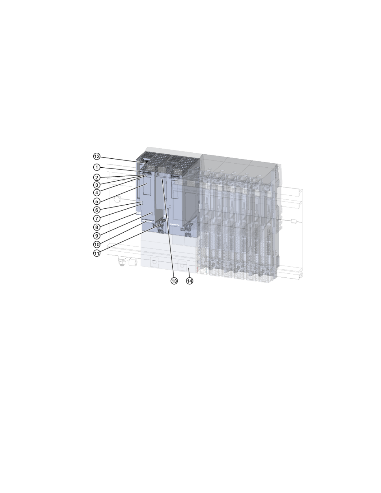
① Module type and designation ⑧ MAC address (specific address for this exact module)
② LED for operating state ⑨ Function status and firmware version
③ LED for diagnostics ⑩ Article number
④ LED for maintenance ⑪ Connector for supply voltage
⑤ 2D matrix code ⑫ Slot for PROFINET BusAdapter
⑥ LED for master operation ⑬ PROFINET BusAdapter
⑦ LED for supply voltage ⑭ Terminal block for interface module (figure: for redundant
interface modules)
Figure 2-1 View of IM 155‑6 PN HA
Properties
The IM 155‑6 PN HA, together with the carrier and BusAdapter, forms the interface of the
ET 200SP HA.
The interface is used for communication between the CPU and the connected ET 200SP HA
I/O modules via PROFINET IO.
Interface Module IM 155-6 PN HA (6DL1155-6AU00-0PM0)
Manual, 05/2017, A5E39262148-AA 7
Page 8

The interface has the following technical properties:
● Supply voltage 1L+ 24 V DC (SELV/PELV).
The supply voltage is fed via the carrier module.
The connection plug is included in the scope of delivery of the interface module.
● PROFINET IO connection via BusAdapter (see following paragraph, "Accessories")
The interface supports the following functions:
● Firmware update
● I&M identification data
● Pulling and plugging modules in RUN
● Value status QI
● IO redundancy
● Time stamping
● Multi Hot Swap (pulling/plugging of multiple I/O modules during operation)
● Saving service data
● Recording the value status of I/O modules
● Reference temperature distribution
You can configure the interface with HW Config and integrate it into your system
Note
The IM 155‑6 PN HA cannot be pulled/plugged when the associated connector for the supply
voltage is plugged in.
PROFINET IO functions
The interface supports the following PROFINET IO functions:
● Integrated BusAdapter with 2 ports
● Supported Ethernet services: ping, arp, network diagnostics (SNMP)/MIB-2, LLDP-MIB and
MRP-MIB
● Port diagnostics
● Disabling of ports
● Minimum update time of 250 µs
● Device replacement without programming device (PG)
● Reset to factory settings via PROFINET IO
● System redundancy S2
● System redundancy R1
● Media redundancy (MRP)
● Support of submodules on suitable I/O modules
Product overview
2.1 Properties
Interface Module IM 155-6 PN HA (6DL1155-6AU00-0PM0)
8 Manual, 05/2017, A5E39262148-AA
Page 9

Accessories
The following accessories must be ordered separately:
BusAdapter
● BusAdapter BA 2×RJ45 (6DL1-6AR00-0AA0) - adapter for Ethernet cable with RJ45
connector
● BusAdapter BA 2×FC (6DL1-6AP00-0AA0) - adapter for direct connection of the Fast
Connect bus cable
● BusAdapter BA 2×LC (6DL1-6AG00-0AA0) - adapter for glass fiber optic cable with
IE FC FO connector
Carrier modules
● Carriers for the IM 155‑6 PN HA are available in the following variants:
– Carrier for one IM 155‑6 PN HA
– Carrier for two IM 155‑6 PN HA for redundant configuration
The carriers connect the IM 155‑6 PN HA to the backplane bus. They enable data exchange
with the I/O modules.
Server module and power bus cover
● The server module and power bus cover are included in the product package of the carrier
module and are available separately as accessories.
● The server module and power bus cover terminate the configuration of the ET 200SP HA.
● Place the server module and the power bus cover at the end of the configuration.
The power bus cover serves to protect the power bus contacts.
Marking options
● Labeling strips
● Reference identification label
Product overview
2.1 Properties
Interface Module IM 155-6 PN HA (6DL1155-6AU00-0PM0)
Manual, 05/2017, A5E39262148-AA 9
Page 10

Product overview
2.1 Properties
Interface Module IM 155-6 PN HA (6DL1155-6AU00-0PM0)
10 Manual, 05/2017, A5E39262148-AA
Page 11
Wiring
3
3.1 Pin assignment
24 V DC supply voltage
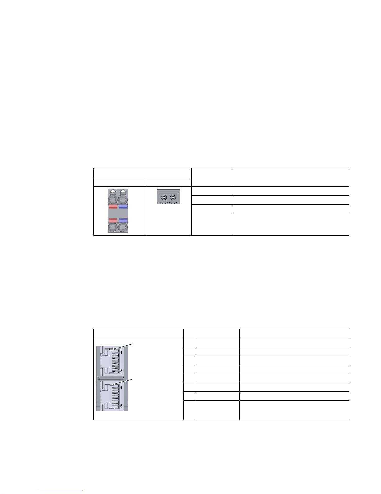
The following table shows the signal names and the descriptions of the pin assignment for a
24 V DC supply voltage.
Table 3-1 Pin assignment 24 V DC supply voltage
View Signal name1Description
Plug IM connection
/
/
0
0
1L+ 24 V DC
2L+ 24 V DC (for looping through)
2
1M Ground
2M Ground (for looping through)
2
1
1L+ and 2L+ as well as 1M and 2M are bridged internally.
2
Maximum 10 A permitted.
Each interface module has its own 24 V connection.
PROFINET IO with BusAdapter BA 2×RJ45
The following table shows the signal name and designation of the pin assignment of the
BusAdapter BA 2×RJ45.
Table 3-2 Pin assignment of PROFINET IO with BusAdapter BA 2×RJ45
View Signal name Description
6KLHOGLQJ
3RUW
3RUW
6KLHOGLQJ
1 TD Transmit data +
2 TD_N Transmit data –
3 RD Receive data +
4 GND Ground
5 GND Ground
6 RD_N Receive data –
7 GND Ground
8 GND Ground
Interface Module IM 155-6 PN HA (6DL1155-6AU00-0PM0)
Manual, 05/2017, A5E39262148-AA 11
Page 12
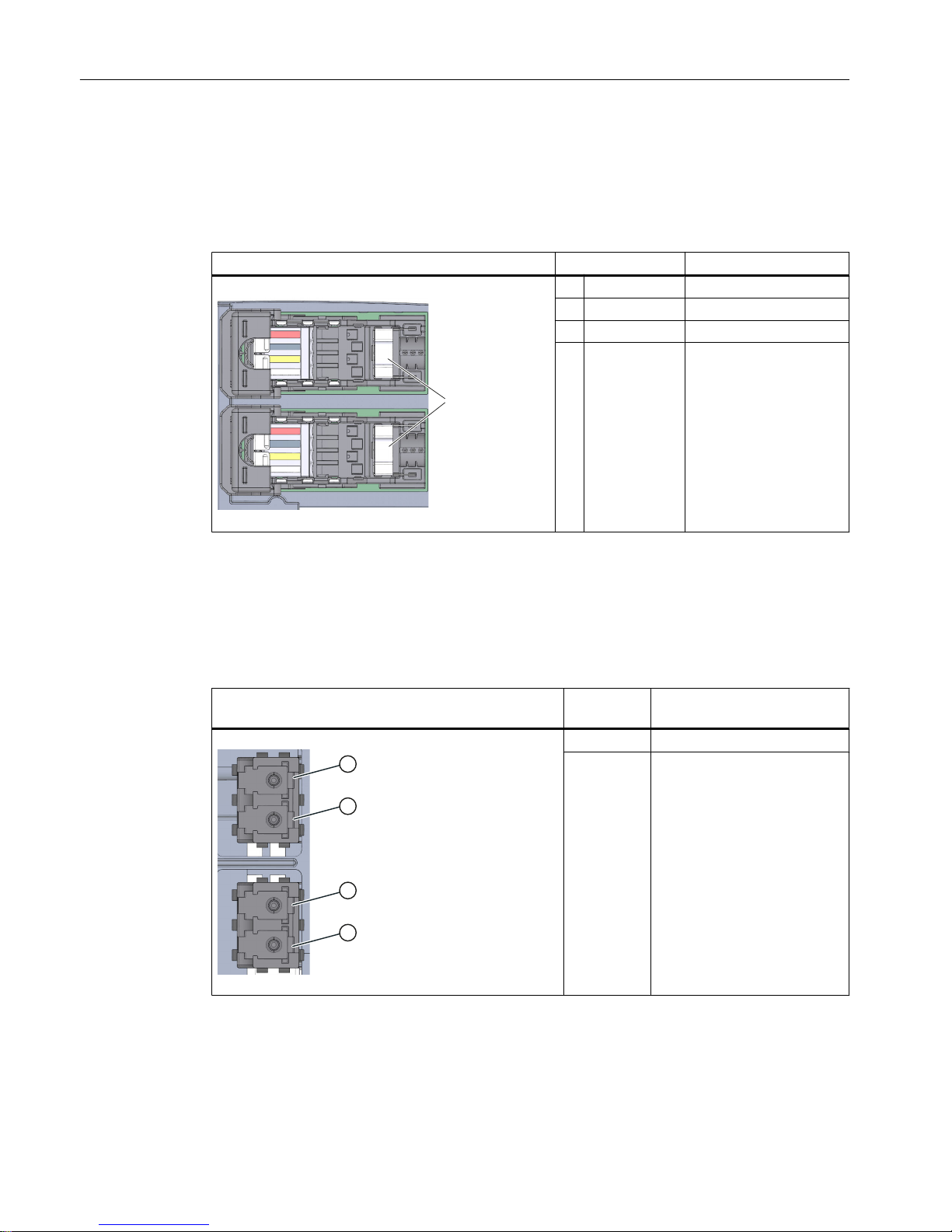
PROFINET IO with BusAdapter BA 2×FC
The following table shows the signal name and designation of the pin assignment of the
BusAdapter BA 2×FC.
Table 3-3 Pin assignment of PROFINET IO with BusAdapter BA 2×FC
View Signal name Description
6KLHOGLQJ
3RUW
3RUW
1 TD Transmit data +
2 TD_N Transmit data –
3 RD Receive data +
4 RD_N Receive data -
PROFINET IO with BusAdapter BA 2×LC
The following table shows the signal name and designation of the pin assignment of the
BusAdapter BA 2×LC.
Table 3-4 Pin assignment of PROFINET IO with BusAdapter BA 2×LC
View Signal
name
Description
3RUW
3RUW
① Receiver / Receive data
② Sender / Transmit data
Wiring
3.1 Pin assignment
Interface Module IM 155-6 PN HA (6DL1155-6AU00-0PM0)
12 Manual, 05/2017, A5E39262148-AA
Page 13
3.2 Schematic circuit diagram
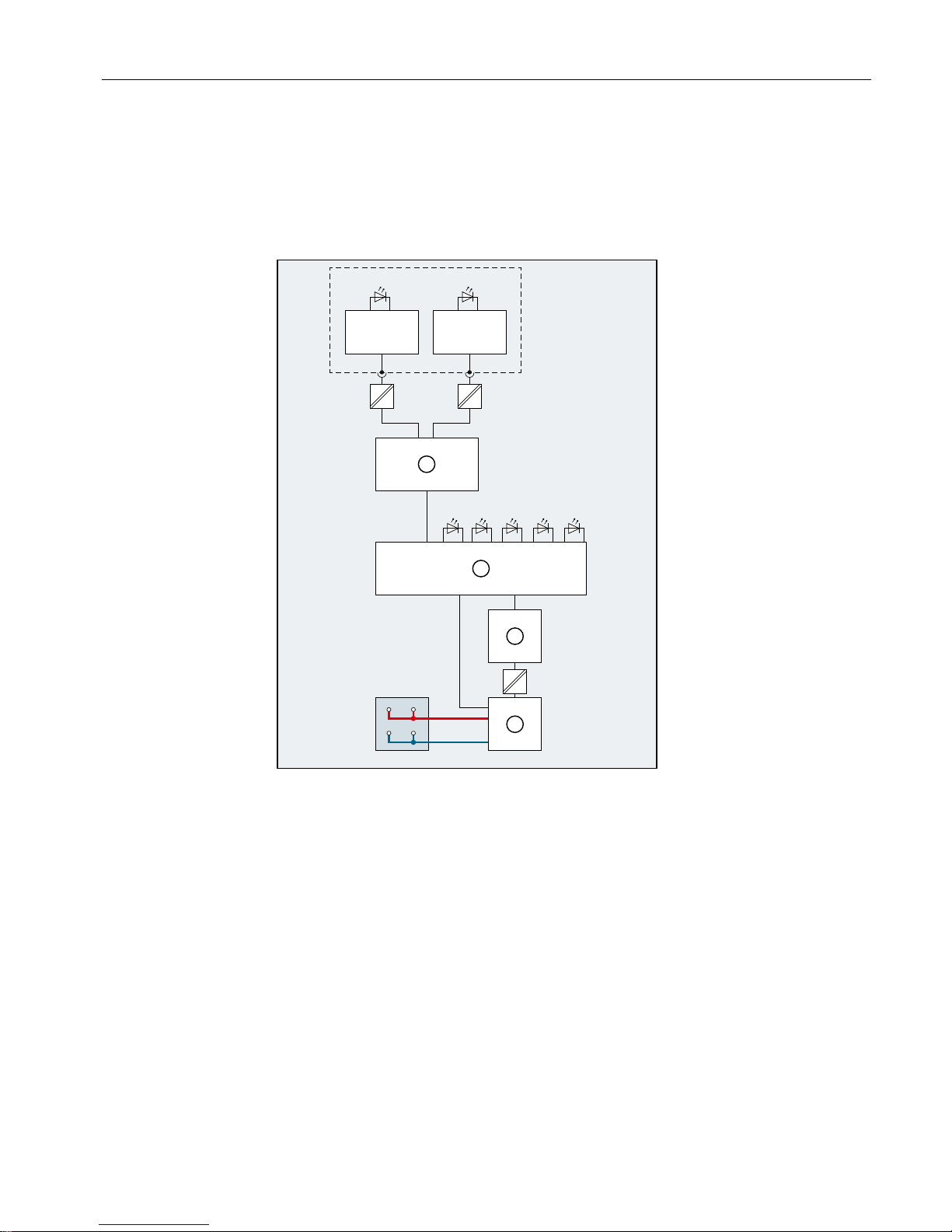
Schematic circuit diagram
The following figure shows the block diagram of the IM 155‑6 PN HA interface module.
/
;'&9
0
3:507(551
3535
;
/./.
$&7
① Switch L+ Supply voltage (24 V DC)
② Backplane bus connection and electronics M Ground
③ Backplane bus LK 1,2 Link TX/RX LED
④ Internal voltage distribution ACT ACT LED
X80 Supply voltage infeed (24 V DC) RN RUN LED (green)
X5 BusAdapter ER ERROR LED (red)
P1 R PROFINET interface X1 Port 1 MT MAINTENANCE LED (yellow)
P2 R PROFINET interface X1 Port 2 PWR Power LED (green)
Figure 3-1 Block diagram for the IM 155-6 PN HA interface module
Wiring
3.2 Schematic circuit diagram
Interface Module IM 155-6 PN HA (6DL1155-6AU00-0PM0)
Manual, 05/2017, A5E39262148-AA 13
Page 14

Wiring
3.2 Schematic circuit diagram
Interface Module IM 155-6 PN HA (6DL1155-6AU00-0PM0)
14 Manual, 05/2017, A5E39262148-AA
Page 15

Parameters
4
4.1 Parameter assignment
Configuring
You configure the ET 200SP HA on a CPU 410 as of FW V8.2.
Parameters
The parameter assignment specifies the properties of the IO device.
Additional information
You can find information on basic procedures and available settings in the following
documentation:
● STEP 7 online help
● Function manual
SIMATIC; ET 200SP HA; ET 200SP HA - High-precision Time Stamping
● When PCS 7 as of V9.0 is used:
– Configuration manual
PCS 7 Process Control System; Engineering System
V9.0
– Function manual
SIMATIC; Process Control System PCS 7; High-precision Time
Stamping with ET 200SP HA
Interface Module IM 155-6 PN HA (6DL1155-6AU00-0PM0)
Manual, 05/2017, A5E39262148-AA 15
Page 16

Parameters
4.1 Parameter assignment
Interface Module IM 155-6 PN HA (6DL1155-6AU00-0PM0)
16 Manual, 05/2017, A5E39262148-AA
Page 17

Maintenance
5
5.1 Exchanging the BusAdapter or interface of the distributed I/O
The device name of the distributed I/O device is saved at the following locations when
transferring the device name to the distributed I/O:
● In the BusAdapter
● In the interface of the distributed I/O device (e.g. interface module or I/O device itself)
Note
Replacing a BusAdapter (removing/inserting)
Removing/inserting the BusAdapter under voltage is prohibited.
Device replacement without transfer of topological configuration
The following scenarios are the result of saving the device name on the BusAdapter and in
the interface when exchanging the two components:
Interface non-program‐
med
(without device name)
Interface with device name
BusAdapter non-programmed
(without device name)
No device names When the supply voltage is switched on,
the device name is copied from the inter‐
face to the BusAdapter.
BusAdapter with device name When the supply voltage is switched on, the device name is copied
from the BusAdapter to the interface.
Note
Restoring the factory settings
Not possible for ET 200SP HA:
The reset to factory settings deletes the device name in the interface and in the BusAdapter.
Avoiding deleting of the device name in the BusAdapter:
Proceed as follows:
1. Pull the BusAdapter from the distributed I/O device.
2. Restore the factory settings of the distributed I/O device.
Interface Module IM 155-6 PN HA (6DL1155-6AU00-0PM0)
Manual, 05/2017, A5E39262148-AA 17
Page 18

Maintenance
5.1 Exchanging the BusAdapter or interface of the distributed I/O
Interface Module IM 155-6 PN HA (6DL1155-6AU00-0PM0)
18 Manual, 05/2017, A5E39262148-AA
Page 19
Displays and interrupts
6
6.1 Status and error displays
LED displays
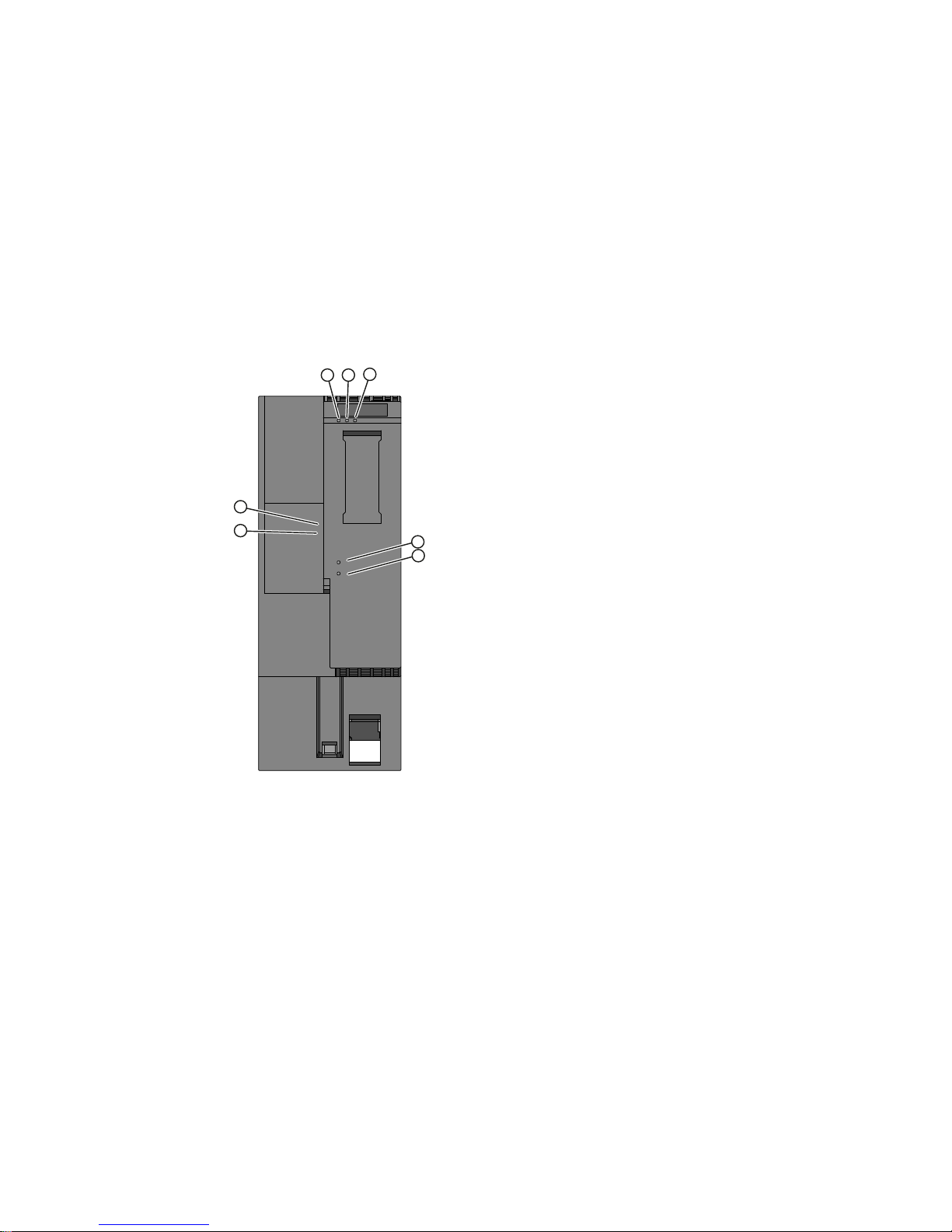
The status and error displays of the IM 155-6 PN HA are shown in the figure below.
SIEMENS
① RN LED (green)
② ER LED (red)
③ MT LED (yellow)
④ ACT LED (green)
⑤ PWR LED (green)
On BusAdapter:
⑥ LED LK1 (green)
⑦ LED LK2 (green)
Figure 6-1 LED displays on the interface module and BusAdapter
Meaning of the LED displays
The following tables provide the meaning of the status, error and maintenance displays. You
can find remedies for diagnostic messages in the section Diagnostics messages and
maintenance events (Page 31)
Interface Module IM 155-6 PN HA (6DL1155-6AU00-0PM0)
Manual, 05/2017, A5E39262148-AA 19
Page 20
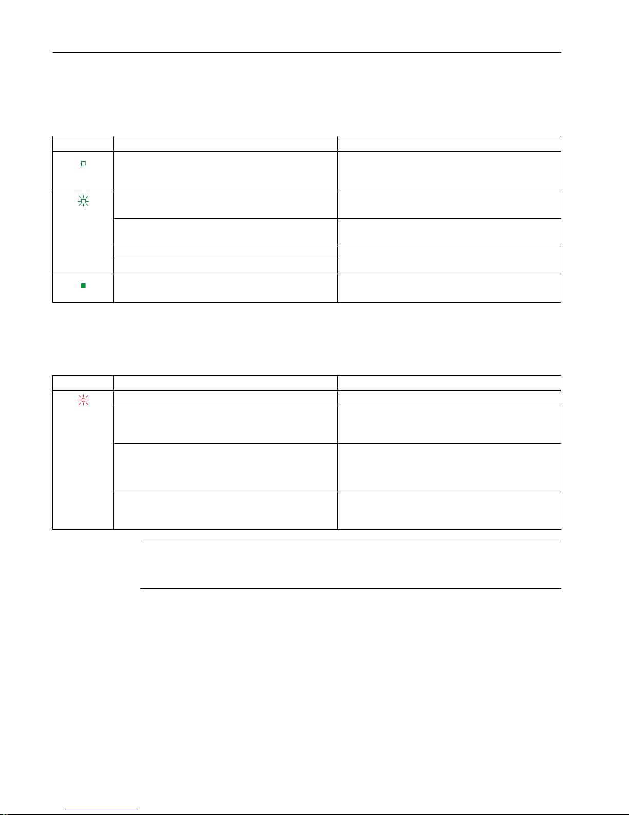
RN LED
Table 6-1 Status and error displays of the RN LED
RN LED Meaning Remedy
Off
No supply voltage or insufficient supply voltage at the
interface module.
Check the supply voltage or switch it on at the inter‐
face module.
Check the backplane bus for short-circuit
Flashes
Interface module is deactivated. Activate the interface module with the configuration
software or the user program.
Interface module is not configured. Configure the interface module with the configuration
software.
ET 200SP HA starts up. --ET 200SP HA parameters are assigned
On
ET 200SP HA is exchanging data with the IO Control‐
ler.
---
ER LED
Table 6-2 Error displays of the ER LED
ER LED Meaning Remedy
Flashes
Group fault and group fault for channels Evaluate the diagnostics and eliminate the error.
Configured settings do not match the actual configu‐
ration of the ET 200SP HA.
Check the configuration of the ET 200SP HA for miss‐
ing modules, defective modules or the presence of
non-configured modules.
Impermissible configuration states You can find information about the hardware configu‐
ration of the ET 200SP HA in the system manual
ET 200SP HA Distributed I/O System
; System Plan‐
ning, Hardware Configuration.
Parameter assignment error in the I/O module Evaluate the display of the module information in HW-
Konfig and eliminate the error in the corresponding I/
O module.
Note
Configuration errors are only checked when the station starts up and not during a CiR or HCiR process.
Displays and interrupts
6.1 Status and error displays
Interface Module IM 155-6 PN HA (6DL1155-6AU00-0PM0)
20 Manual, 05/2017, A5E39262148-AA
Page 21
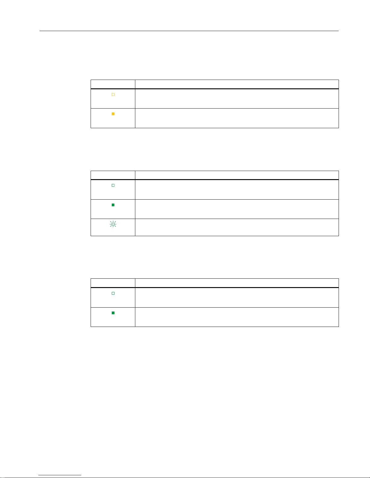
MT LED
Table 6-3 Maintenance display of the MT LED
MT LED Meaning
Off
Maintenance is not required.
On
Maintenance is required, meaning that at least one maintenance event has occurred.
ACT LED
Table 6-4 Status display of the ACT LED
ACT LED Meaning (only relevant for IO device with redundant IM)
Off
There is no active data exchange with the I/O modules via this IM.
On
There is an active data exchange with the I/O modules via this IM.
The partner IM can apply the data exchange.
Flashes
There is an active data exchange with the I/O modules via this IM.
The partner IM cannot apply the data exchange.
PWR LED
Table 6-5 Status display of the PWR LED
PWR LED Meaning
Off
Missing supply voltage or insufficient supply voltage at the interface module.
On
Supply voltage L+ available.
Displays and interrupts
6.1 Status and error displays
Interface Module IM 155-6 PN HA (6DL1155-6AU00-0PM0)
Manual, 05/2017, A5E39262148-AA 21
Page 22
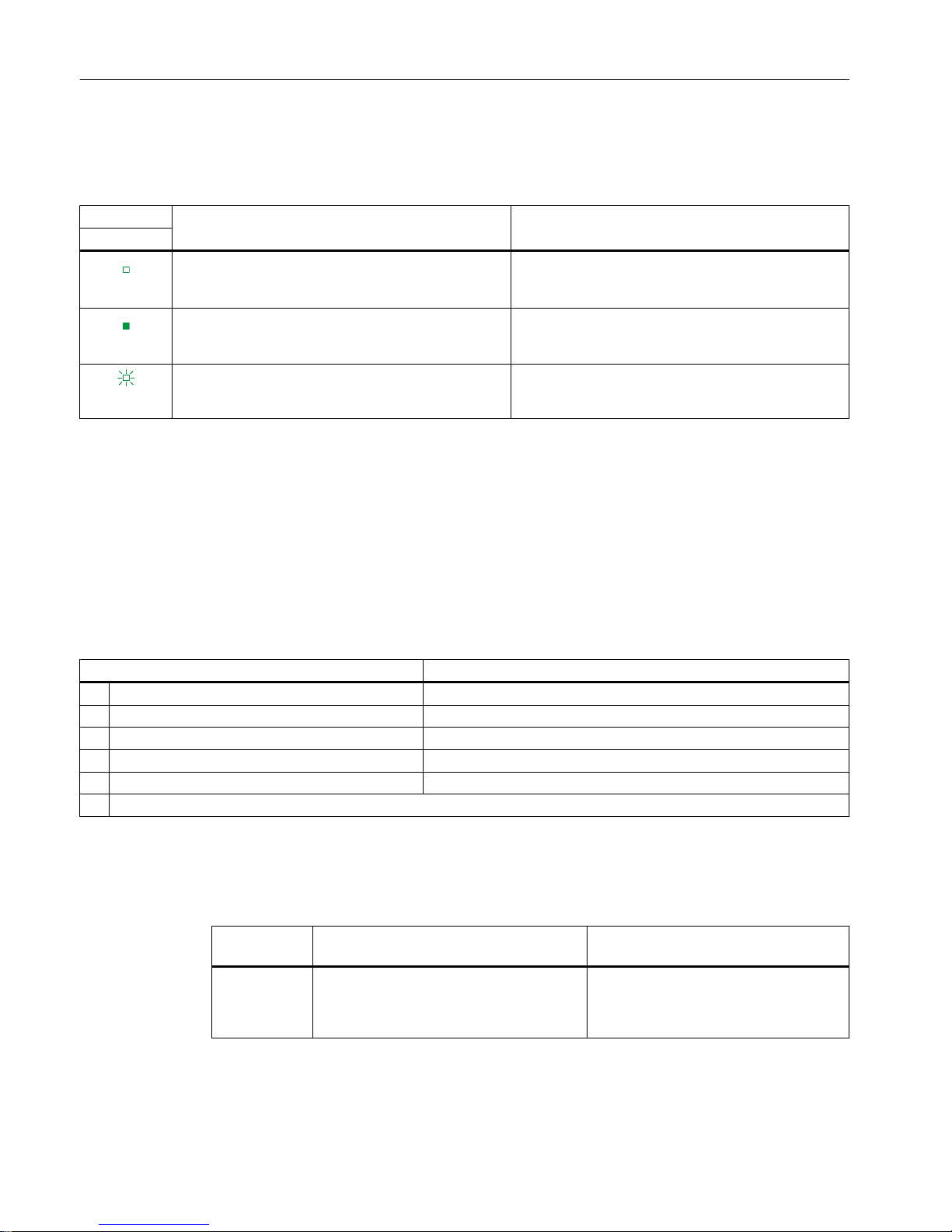
LK1/LK2 LEDs on the BusAdapter
Table 6-6 Status and error displays of the LK1/LK2 LEDs
LED Meaning Remedy
LK1/LK2
Off
There is no Ethernet connection between the PROFI‐
NET IO interface of your PROFINET device and a
communication partner (e.g. IO controller).
Check whether the bus cable to the switch/IO control‐
ler is interrupted.
On
There is an Ethernet connection between the PROFI‐
NET IO interface of your PROFINET device and a
communication partner (e.g. IO controller).
---
Flashes
The "Node flash test" is run (the RN/ER/MTLEDs also
flash).
---
Operating principle
The LED error display provides information on the cause of the error. After notification by the
flash signal, the error type is displayed followed by the error location/error code.
The LED error display
● takes precedence over all other states that are displayed by the ERROR and MAINT LEDs.
● remains switched on until the cause of the error is eliminated
Table 6-7 Display of error type and error location
Sequence Description
1 ER and MT LEDs flash 3x at 0.5 Hz Indication of the error type
2 MT LED flashes at 1 Hz Display of error type (decimal)
3 ER and MT LEDs flash 3x at 2 Hz Indication of error location/error code
4 ER LED flashes at 1 Hz Display of tens digit (decimal) of the error location / error code
5 MT LED flashes at 1 Hz Display of ones digit (decimal) of the error location / error code
6 Repeat steps 1 to 5 until the cause of the error has been eliminated.
Error display
Table 6-8 Error display
Error type
(MAINT)
Cause of error Solution
1
● No server module
● Interruptions on the backplane bus
● Short-circuit on backplane bus
Check the configuration of the
ET 200SP HA.
Displays and interrupts
6.1 Status and error displays
Interface Module IM 155-6 PN HA (6DL1155-6AU00-0PM0)
22 Manual, 05/2017, A5E39262148-AA
Page 23

Note
The following LEDs indicate a short-circuit in the backplane bus supply or in the bus connection
supply:
● LED PWR: On
● LED RN, ER and MT: Off
6.2 Interrupts
Diagnostics interrupts
Diagnostic interrupts are used by the IM 155-6 PN HA to signal diagnostic messages as well
as maintenance events, see also appendix Diagnostics messages and maintenance events
(Page 31)
The IM 155-6 PN HA generates a diagnostic interrupt for the following events:
● Faulty 24 V DC power supply
● Module parameter errors or incorrect carrier present in real slot
● Failure of redundancy partner
● Redundancy partners have different hardware/firmware
● Impermissible bus adapter on interface module
● Incorrect bus adapter in redundancy partner
● Defective retentive memory in bus adapter
● Permissible backplane bus size exceeded
● No server module
Diagnostics of I/O modules are forwarded by the IM 155-6 PN HA and depend on the respective
I/O module.
Maintenance messages
The IM 155-6 PN HA generates a maintenance message for the following events:
● Different hardware/firmware in the redundancy partners
● IO redundancy warning
● Redundancy parameter assignment inconsistent
● Retentive memory in carrier module defective
● Defective retentive memory in bus adapter
Displays and interrupts
6.2 Interrupts
Interface Module IM 155-6 PN HA (6DL1155-6AU00-0PM0)
Manual, 05/2017, A5E39262148-AA 23
Page 24

Displays and interrupts
6.2 Interrupts
Interface Module IM 155-6 PN HA (6DL1155-6AU00-0PM0)
24 Manual, 05/2017, A5E39262148-AA
Page 25
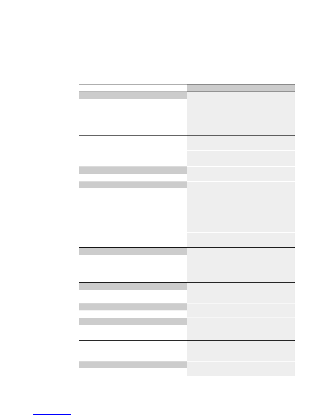
Technical specifications
7
Article number 6DL1155-6AU00-0PM0
General information
Product type designation IM 155-6 PN
HW functional status FS01
Firmware version V1.0
Vendor identification (VendorID) 02AH
Device identifier (DeviceID) 030FH
Product function
● I&M data
Yes; I&M0 to I&M3
Engineering with
● PCS 7 configurable/integrated as of version
V9.0
Configuration control
via dataset No
Supply voltage
Type of supply voltage DC
Rated value (DC) 24 V
permissible range, lower limit (DC) 19.2 V
permissible range, upper limit (DC) 28.8 V
Reverse polarity protection Yes
Short-circuit protection Yes
Mains buffering
● Mains/voltage failure stored energy time
10 ms
Input current
Current consumption, max. 700 mA; +19.2 V to +28.8 V DC
Inrush current, max. 5 A
I²t 0.36 A²·s; Due to increased mains buffering of 10
ms
Power
Infeed power to the backplane bus 7.5 W; No doubling in redundant mode as the in‐
feed power is also designed as redundant.
Power loss
Power loss, typ. 2.4 W
Address area
Address space per module
● Address space per module, max.
256 byte
Address space per station
● Address space per station, max.
1 440 byte; 1 440 bytes R1 and S1 without CiR,
otherwise 1 000 bytes
Hardware configuration
Integrated power supply Yes; 24 V DC
Interface Module IM 155-6 PN HA (6DL1155-6AU00-0PM0)
Manual, 05/2017, A5E39262148-AA 25
Page 26
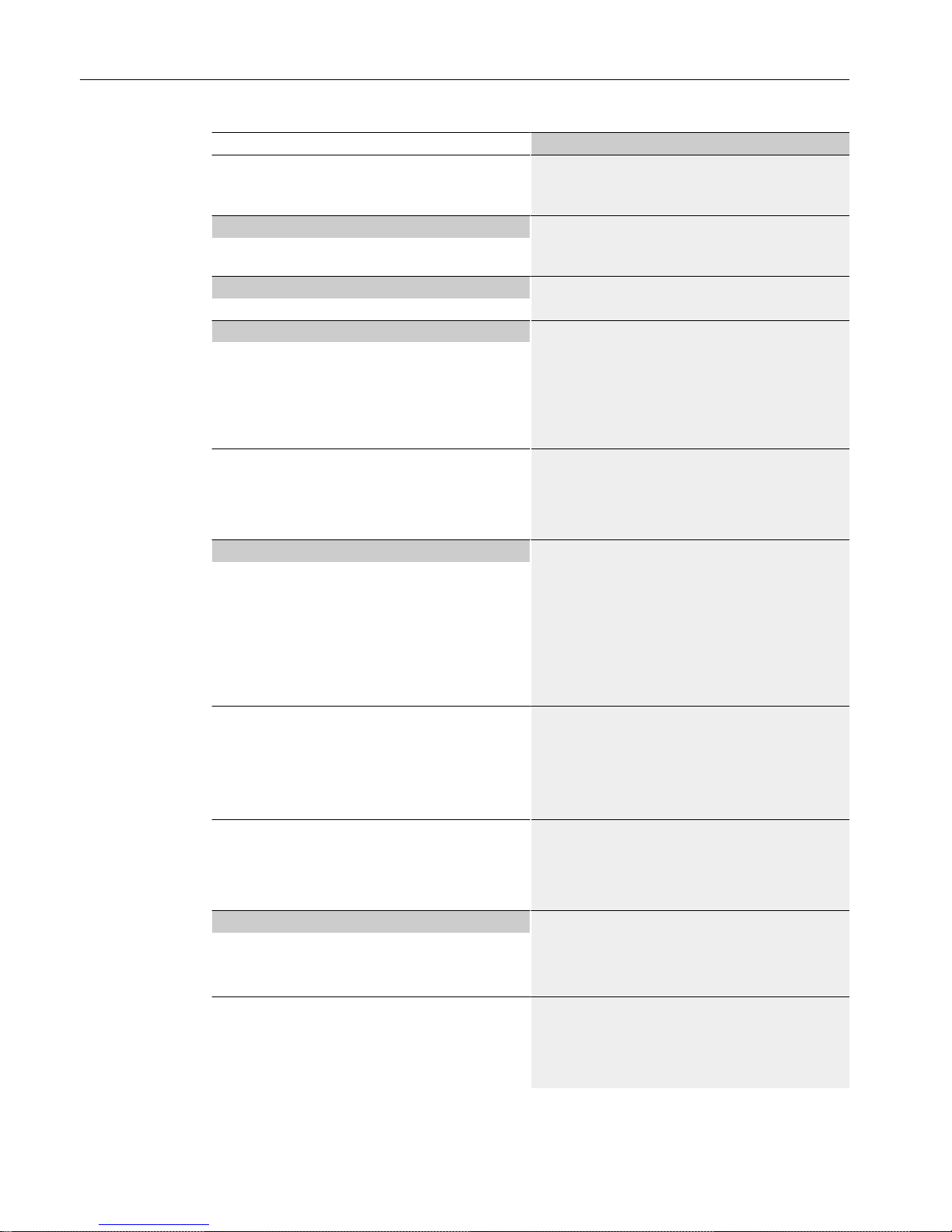
Article number 6DL1155-6AU00-0PM0
Rack
● Modules per rack, max.
56; 56 slots for I/O modules + server module (width
without IM ≤ 1.3 m)
Time stamping
Accuracy 1 ms; In compliance with the supplementary con‐
ditions described in the Equipment Manual
Interfaces
Number of PROFINET interfaces 1; 2 ports (switch)
1. Interface
Interface types
● Number of ports
2; via BusAdapter
● integrated switch
Yes
● BusAdapter (PROFINET)
Yes; Compatible BusAdapters: BA 2x RJ45, BA 2x
FC, BA 2x LC
Functionality
● PROFINET IO Device
Yes
● Open IE communication
Yes
● Media redundancy
Yes; as MRP client
Interface types
RJ 45 (Ethernet)
● Transmission procedure
PROFINET with 100 Mbit/s full duplex (100BASETX)
● 100 Mbps
Yes; PROFINET with 100 Mbit/s full duplex
(100BASE-TX)
● Autonegotiation
Yes
● Autocrossing
Yes
PROFINET IO Device
Services
– Open IE communication
Yes
– MRP
Yes
– PROFINET system redundancy
Yes; S2, R1
Open IE communication
● TCP/IP
Yes
● SNMP
Yes
● LLDP
Yes
Interrupts/diagnostics/status information
Status indicator Yes
Alarms Yes
Diagnostic functions Yes
Diagnostics indication LED
● RUN LED
Yes; Green LED
● ERROR LED
Yes; Red LED
● MAINT LED
Yes; yellow LED
Technical specifications
Interface Module IM 155-6 PN HA (6DL1155-6AU00-0PM0)
26 Manual, 05/2017, A5E39262148-AA
Page 27
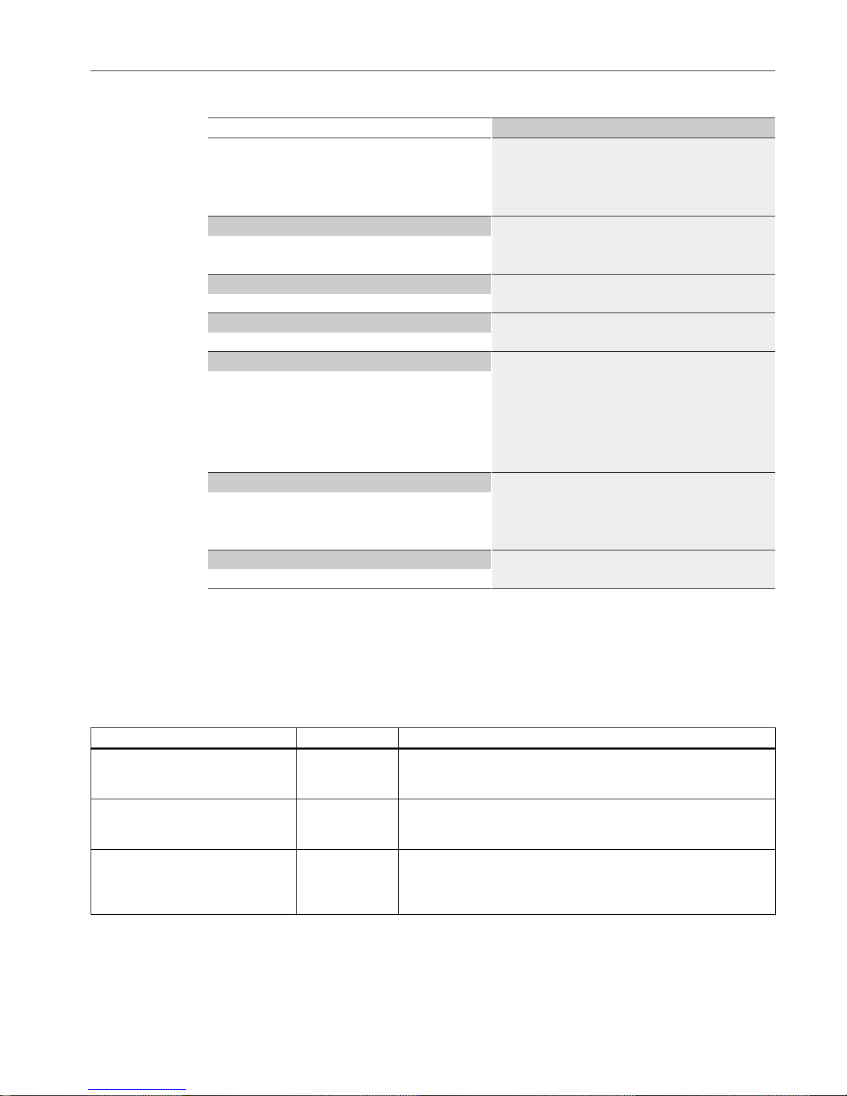
Article number 6DL1155-6AU00-0PM0
● ACTIVE-LED (active IM in redundant
configuration)
Yes; Green LED
● Monitoring of the supply voltage (PWR-LED)
Yes; green PWR LED
● Connection display LINK TX/RX
Yes; 2x green link LEDs on BusAdapter
Potential separation
between PROFINET and all other circuits Yes; 1500 V AC
between supply and all other circuits Yes; Type tested with 1 500 V DC
Permissible potential difference
between different circuits Safety extra low voltage SELV
Isolation
Isolation tested with 1 500 V DC/1 min, type test
Ambient conditions
Ambient temperature during operation
● horizontal installation, min.
-40 °C
● horizontal installation, max.
70 °C
● vertical installation, min.
-40 °C
● vertical installation, max.
60 °C
Dimensions
Width 50 mm
Height 138 mm
Depth 89 mm
Weights
Weight, approx. 192 g; without BusAdapter
Supplemental information on the address space for each operating mode
The size of user data attachment of the I/O modules depends on the type (1 byte if only input
or output address space are allocated, or 2 bytes if both address spaces are allocated). You
can determine the allocated address space from the technical specifications in the manuals
of the I/O modules.
Configuration Operating mode Address space
Redundant IM on H system R1 mode 1440 bytes (of which I/O: 1432 bytes for the address space and
PROFINET user data attachment of the I/O modules, 8 bytes
for PROFINET user data attachment of the IM)
Single IM on H system S2 mode 1000 bytes (of which I/O: 996 bytes for the address space and
PROFINET user data attachment of the I/O modules, 4 bytes for
PROFINET user data attachment of the IM)
Single IM on single CPU S1 mode 1000 bytes with CiR capability, or 1440 bytes without CiR capability
(including I/O: 996/1436 bytes for the address space and PROFI‐
NET user data attachment of the I/O modules, 4 bytes for PROFI‐
NET user data attachment of the IM)
Technical specifications
Interface Module IM 155-6 PN HA (6DL1155-6AU00-0PM0)
Manual, 05/2017, A5E39262148-AA 27
Page 28
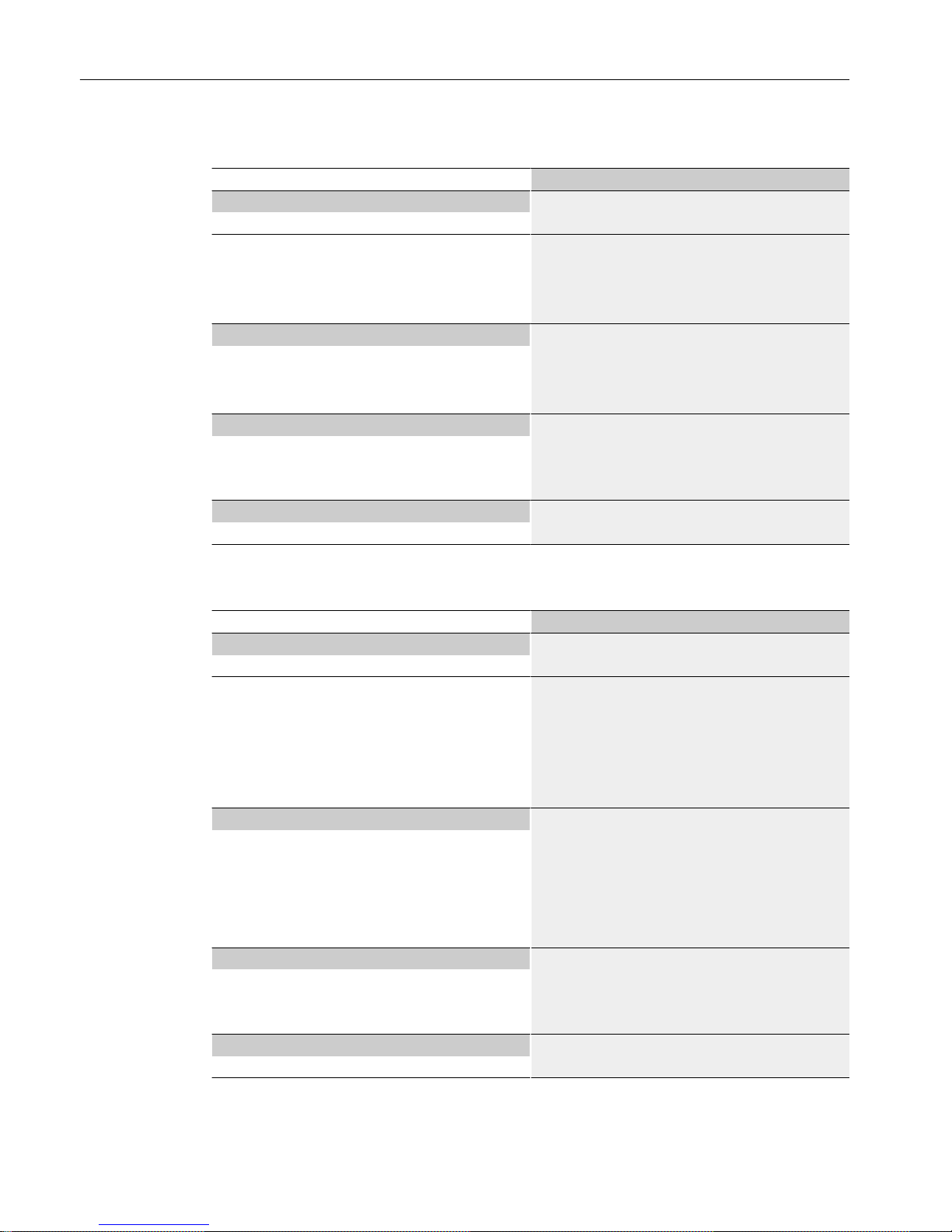
Article number 6DL1193-6AR00-0AA0
Interfaces
Number of PROFINET interfaces 1; 2 ports (switch) RJ45
PROFINET IO
● RJ 45
Yes; 2x RJ45
Cable length
– Cu conductors
100 m
Ambient conditions
Ambient temperature during operation
● min.
-40 °C
● max.
70 °C
Dimensions
Width 20 mm
Height 69.5 mm
Depth 59 mm
Weights
Weight, approx. 46 g
Article number 6DL1193-6AG00-0AA0
Interfaces
Number of PROFINET interfaces 1; 2 ports (switch) LC Multimode Glass Fibre
PROFINET IO
● Number of LC ports
2
Cable length
– Multimode graded-index fiber 50/125 µm
3 km
– Multimode graded-index fiber 62.5/125
μm
3 km
Ambient conditions
Ambient temperature during operation
● min.
-40 °C
● max.
65 °C; Redundant design (2x
6DL1155-6AU00-0PM0): max. 60 °C horizontal,
max. 50 °C vertical. When using different I/O devi‐
ces, the derating specified there must be observed.
Dimensions
Width 20 mm
Height 75 mm; Without protective caps (approx. 8 mm)
Depth 59 mm
Weights
Weight, approx. 60 g
Technical specifications
Interface Module IM 155-6 PN HA (6DL1155-6AU00-0PM0)
28 Manual, 05/2017, A5E39262148-AA
Page 29

Article number 6DL1193-6AF00-0AA0
Interfaces
Number of PROFINET interfaces 1; 2 ports (switch) FC
PROFINET IO
● FC (FastConnect)
Yes; 2 x
Cable length
– Cu conductors
100 m
Ambient conditions
Ambient temperature during operation
● min.
-40 °C
● max.
70 °C
Dimensions
Width 20 mm
Height 69.5 mm
Depth 59 mm
Weights
Weight, approx. 53 g
Supplemental information on the address space for each operating mode
The size of user data attachment of the I/O modules depends on the type (1 byte if only input
or output address space are allocated, or 2 bytes if both address spaces are allocated). You
can determine the allocated address space from the technical specifications in the manuals
of the I/O modules.
Technical specifications
Interface Module IM 155-6 PN HA (6DL1155-6AU00-0PM0)
Manual, 05/2017, A5E39262148-AA 29
Page 30

Technical specifications
Interface Module IM 155-6 PN HA (6DL1155-6AU00-0PM0)
30 Manual, 05/2017, A5E39262148-AA
Page 31

Diagnostic messages
A
A.1 Diagnostics messages and maintenance events
Diagnostic messages
For each diagnostic event, a diagnostic message is output and the ER LED flashes on the
module.
The diagnostic messages can, for example, be read from the diagnostic buffer of the CPU.
There can be more than one diagnostics alarm at the same time.
Table A-1 Diagnostic messages, their meaning and possible remedies
Diagnostics message Channel
error type
(CET)
Extended
channel
error type
(CET)
Assignment Meaning Remedy
Configuration error:
Station Stop – No
server module
0x0602 0x0693 Configura‐
tion
No server module was present
during power-up of an
ET 200SP HA station.
Verify that the server mod‐
ule is correctly installed in
the rack.
Configuration error:
Station Stop – Mod‐
ule parameter <po‐
tential group> errors
or incorrect terminal
block present in real
slot <slot>
0x0602 0x0691 Configura‐
tion
The installed terminal block
does not match the configura‐
tion.
Ensure that a matching ter‐
minal block is installed.
Configuration error:
Permissible back‐
plane bus size excee‐
ded
0x0602 0x0698 Configura‐
tion
The total width of the installed
modules exceeds the permissi‐
ble assembly length of
1300 mm.
Verify that the backplane
bus configuration does not
exceed the permissible size.
The server module must be
the last module plugged in
(highest permissible slot
number: 58).
Configuration error:
Incorrect backplane
bus configuration in
slot <slot>
0x0602 0x0699 Configura‐
tion
The maximum current demand
of all plugged-in modules ex‐
ceeds 2100 mA.
The accompanying <slot> val‐
ue indicates the slot causing
the error.
Check the configuration of
the ET 200SP HA.
Configuration error:
Impermissible bus
adapter on interface
module
0x0602 0x069C Configura‐
tion
The installed bus adapter does
not match the configuration.
Verify that a matching bus
adapter is installed.
Configuration error:
No server module
0x0602 0x069E Configura‐
tion
The server module is pulled
during operation of an
ET 200SP HA station.
Ensure that the server mod‐
ule is correctly installed in
the rack.
Interface Module IM 155-6 PN HA (6DL1155-6AU00-0PM0)
Manual, 05/2017, A5E39262148-AA 31
Page 32

Diagnostics message Channel
error type
(CET)
Extended
channel
error type
(CET)
Assignment Meaning Remedy
Redundancy error:
Failure in the partner
module <internal er‐
ror code>
0x0630 0x06D0 Redundant
modules
Errors in the redundancy of the
interface module are signaled.
The accompanying <internal
error code> value provides in‐
formation for service experts.
Replace the partner inter‐
face module.
Redundancy error:
Faulty power supply
0x0630 0x06D1 Redundant
modules
Problems with the power sup‐
ply.
Check the power supply for
possible errors, e.g. over‐
load, short-circuit.
Replace the interface mod‐
ule, if necessary/
Redundancy error:
Incorrect bus adapter
in partner module
0x0630 0x06D2 Redundant
modules
The bus adapter of the redun‐
dancy partner module is not
present or is not supported.
Replace the bus adapter in
the partner module.
Maintenance events
A maintenance event is generated each time a maintenance requirement is identified. The MT
LED lights up on the module.
Maintenance messages do not directly affect the function of the module.
Table A-2 Maintenance messages, their meaning and possible remedies
Maintenance mes‐
sage
Channel
error type
(CET)
Extended
channel
error type
(CET)
Assignment Meaning / Cause Remedy
Error in the retentive
memory of the inter‐
face module
0x0640 0x06E0 Module Fault detected in the data
block on the mounting module
during operation
Replace carrier module
Error in the retentive
memory of the BusA‐
dapter
0x0640 0x06E1 Module A memory block error on the
bus adapter was detected dur‐
ing operation.
Replace the bus adapter.
PROFINET IO
Another source of diagnostic events is the PROFINET basic technology in use. It generates
diagnostics messages containing coding that is already defined in the PROFINET IO Standard
- Application Layer Service Definition V2.2.
The actual diagnostics scope used depends on the configuration and parameter assignment.
You can download the standard as needed on the Internet (
http://www.profibus.com) from the
home page of the PROFIBUSuser organization.
Diagnostic messages
A.1 Diagnostics messages and maintenance events
Interface Module IM 155-6 PN HA (6DL1155-6AU00-0PM0)
32 Manual, 05/2017, A5E39262148-AA
 Loading...