

Page 1
Information and Communication
Communication Devices
E10 / S6 Power GSM /S8 GSM
Level 2.5
Repair Documentation
V 1.2
V1.2 Page 1 of 23 ICP CD ST
D. Schnoor
06/98
Page 2

Information and Communication
Communication Devices
Table of Contents:
1 INTRODUCTION................................................................................................................................................2
2 VCXO
...................................................................................................................................................................................3
3 FUSE 1A
...................................................................................................................................................................................8
4 FUSE 0.25 A
.................................................................................................................................................................................12
5 MOLEX CONNECTOR
.................................................................................................................................................................................16
6 RINGER
.................................................................................................................................................................................20
1Introduction
V1.2 Page 2 of 23 ICP CD ST
D. Schnoor
06/98
Page 3
Information and Communication
Communication Devices
This manual is intended to help you carry out repairs on level 2.5, meaning limited
component repairs. Failure highlights are documented and should be repaired in the local
workshops.
The E10 and the S6 Power GSM are both handsets for GSM-900. Internally they are almost
identical but the form factors of the boards are different.
Note: In some countries the S6 Power GSM is called S6 Classic!
It must be noted that all repairs have to be carried out in an environment set up according to
the ESD (Electrostatic Discharge Sensitive Devices) regulations defined in international
standards.
If you have any questions regarding the repair procedures or spare parts do not hesitate to
contact our technical support team in Kamp-Lintfort, Germany:
Tel.: +49 2842 95 4666
Fax: +49 2842 95 4302
e-mail: dominik.schnoor@klf.siemens.de
2VCXO
2.1Affected Units
2.1.1Type: E10 / S6 Power GSM
V1.2 Page 3 of 23 ICP CD ST
D. Schnoor
06/98
Page 4

Information and Communication
Communication Devices
2.1.2Affected IMEIs / Date Codes: All / All
2.1.3Affected SW-Versions: All
2.1.4Fault Code for LSO reporting: 3VCX
2.2Fault Description
2.2.1Fault Symptoms for customers:
Network Search
Handset not logging into network
2.2.2Fault Symptom on GSM-Tester:
Frequency error in synchronized mode >90 Hz
No location update possible
The VCXO (Voltage Controlled Crystal Oscillator) is responsible for generating the
13 MHz reference frequency of the handset.
If it is defective, the handset cannot synchronize to the base station anymore.
2.3Priority:
........ Mandatory
........ Repair
........ Optional
........ Not Yet Defined
2.4Repair Documentation
2.4.1Description of procedure:
2.4.1.1Diagnosis
Check the output frequency of the VCXO using the level-2 testing
program for E10 / S6 Power GSM.
Switch off the „CMD in Use“ option in the S611.INI file and restart
V1.2 Page 4 of 23 ICP CD ST
D. Schnoor
06/98
Page 5

Information and Communication
Communication Devices
the program. Start the test, when the program says „Check power and
phase of external antenna with your GSM-Tester“, switch the CMD to
„LOCAL“ mode and enter the „MODULE TEST“.
On the CMD display you can see the frequency error of the handset.
(Make sure that the CMD is on channel 124, power level 5!)
If the frequency error is higher than 2kHz, the VCXO has to be
replaced.
2.4.1.2Repair by component change
Use hot air blower to remove defective VCXO.
Avoid excessive heat!
Watch surrounding components!
Resolder new VCXO afterwards.
2.4.1.3Repair by SW-Booting
Not possible!
2.4.1.4Test
Retest handset after repair as described above.
The frequency error must now be < 2kHz.
2.4.2List of needed material
2.4.2.1Components
VCXO
Part-Number: L36145-G300-Y19
2.4.2.2 Jigs and Tools
V1.2 Page 5 of 23 ICP CD ST
D. Schnoor
06/98
Page 6

Information and Communication
Communication Devices
Hot Air Blower
Soldering Iron
2.4.2.3Special Tools
None
2.4.2.4Working materials
Desolder Wick / Braid
Solder
V1.2 Page 6 of 23 ICP CD ST
D. Schnoor
06/98
Page 7
Information and Communication
Communication Devices
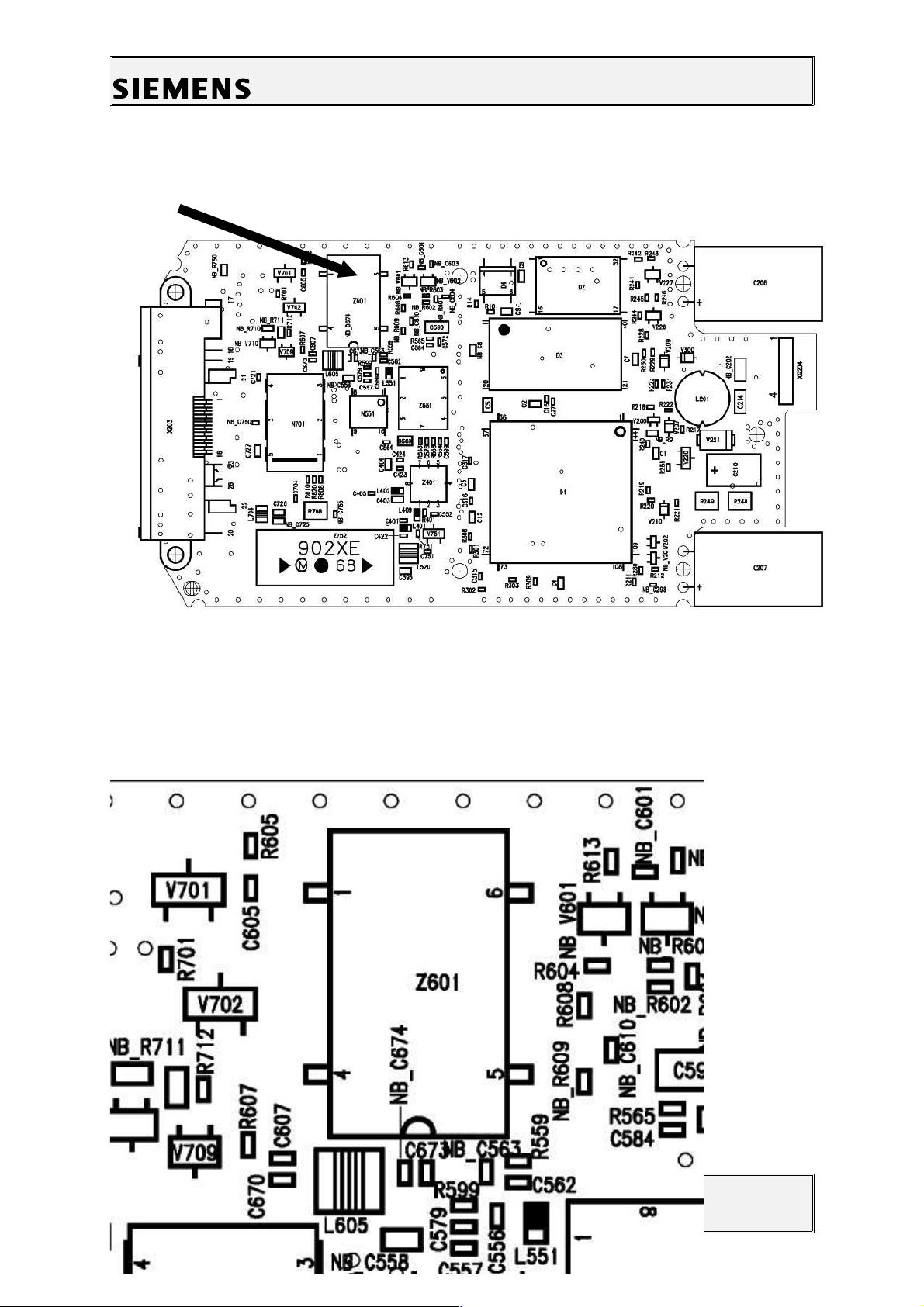
2.4.3Drawings
V1.2 Page 7 of 23 ICP CD ST
D. Schnoor
06/98
Figure 1: E10 / S6 Power GSM Board VCXO Side
Figure 2: VCXO (Z601) Placement (Top View)
Page 8

Information and Communication
Communication Devices
3Fuse 1A
3.1Affected Units
3.1.1Type: E10 / S6 Power GSM
3.1.2Affected IMEIs / Date Codes: All / All
3.1.3Affected SW-Versions: All
3.1.4Fault Code for LSO reporting: 3FU1
3.2Fault Description
3.2.1Fault Symptoms for customers:
Battery charging not possible
3.2.2Fault Symptom on GSM-Tester:
This fault cannot be detected with a GSM-Tester
3.3Priority:
........ Mandatory
........ Repair
........ Optional
........ Not Yet Defined
V1.2 Page 8 of 23 ICP CD ST
D. Schnoor
06/98
Page 9

Information and Communication
Communication Devices
3.4Repair Documentation
3.4.1Description of procedure:
3.4.1.1Diagnosis
Check the status of the fuse by measuring its resistance with
a multimeter. The fuse is defective if the resistance higher than 10
ohms.
3.4.1.2Repair by component change
Use soldering iron to remove defective fuse.
Avoid excessive heat!
Watch surrounding components!
Resolder new fuse afterwards.
3.4.1.3Repair by SW-Booting
Not possible!
3.4.1.4Test
Retest handset after repair as described above.
The resistance must now be close to zero.
V1.2 Page 9 of 23 ICP CD ST
D. Schnoor
06/98
Page 10

Information and Communication
Communication Devices
3.4.2List of needed material
3.4.2.1Components
Fuse
Part-Number: L36145-A820-Y7
3.4.2.2Jigs and Tools
Soldering Iron
3.4.2.3Special Tools
Multimeter
3.4.2.4Working materials
Desolder Wick / Braid
Solder
3.4.3Drawings
V1.2 Page 10 of 23 ICP CD ST
D. Schnoor
06/98
Page 11

Information and Communication
Communication Devices
V1.2 Page 11 of 23 ICP CD ST
D. Schnoor
06/98
Figure 1: E10 / S6 Power GSM Board 1A Fuse Side
Figure 2: 1A Fuse (F201) Placement (Top View)
Page 12

Information and Communication
Communication Devices
4Fuse 0.25 A
4.1Affected Units
4.1.1Type: E10 / S6 Power GSM
4.1.2Affected IMEIs / Date Codes: All / All
4.1.3Affected SW-Versions: All
4.1.4Fault Code for LSO reporting: 3FU2
4.2Fault Description
4.2.1Fault Symptoms for customers:
Supplying of external accessories through the handset’s
bottom connector is not possible
V1.2 Page 12 of 23 ICP CD ST
D. Schnoor
06/98
Page 13

Information and Communication
Communication Devices
4.2.2Fault Symptom on GSM-Tester:
This fault cannot be detected with a GSM-Tester
4.3Priority:
........ Mandatory
........ Repair
........ Optional
........ Not Yet Defined
4.4Repair Documentation
4.4.1Description of procedure:
4.4.1.1Diagnosis
Check the status of the fuse by measuring its resistance with
a multimeter. The fuse is defective if the resistance higher than 10
ohms
4.4.1.2Repair by component change
Use soldering iron to remove defective fuse.
Avoid excessive heat!
Watch surrounding components!
Resolder new fuse afterwards.
4.4.1.3Repair by SW-Booting
Not possible!
4.4.1.4Test
Retest handset after repair as described above.
The resistance must now be close to zero.
V1.2 Page 13 of 23 ICP CD ST
D. Schnoor
06/98
Page 14

Information and Communication
Communication Devices
4.4.2List of needed material
4.4.2.1Components
Fuse
Part-Number: L36145-A820-Y10
4.4.2.2Jigs and Tools
Soldering Iron
4.4.2.3Special Tools
Multimeter
4.4.2.4Working materials
Desolder Wick / Braid
Solder
4.4.3Drawings
V1.2 Page 14 of 23 ICP CD ST
D. Schnoor
06/98
Figure 1: E10 / S6 Power GSM 0.25A Fuse Side
Page 15

Information and Communication
Communication Devices
V1.2 Page 15 of 23 ICP CD ST
D. Schnoor
06/98
Page 16

Information and Communication
Communication Devices
5Molex Connector
5.1Affected Units
5.1.1Type: E10 / S6 Power GSM
5.1.2Affected IMEIs / Date Codes: All / All
5.1.3Affected SW-Versions: All
5.1.4 Fault Code for LSO reporting: 3MOC
V1.2 Page 16 of 23 ICP CD ST
D. Schnoor
06/98
Figure 2: E10 / S6 Power GSM 0.25A Fuse Placement
Page 17

Information and Communication
Communication Devices
5.2Fault Description
5.2.1Fault Symptoms for customers:
Network search.
Charging or operation in a car kit not possible.
5.2.2Fault Symptom on GSM-Tester:
Output power problems on the external and internal
antenna.
No location update possible.
5.3Priority:
........ Mandatory
........ Repair
........ Optional
........ Not Yet Defined
5.4Repair Documentation
5.4.1Description of procedure:
5.4.1.1Diagnosis
Visually check the bottom connector. Watch for dry joints.
5.4.1.2Repair by component change
Use hot air blower to remove defective connector.
Avoid excessive heat!
Watch surrounding components!
Resolder new connector afterwards.
Make sure that you use just very little flux, otherwise the connector
contacts can become dirty.
5.4.1.3Repair by SW-Booting
V1.2 Page 17 of 23 ICP CD ST
D. Schnoor
06/98
Page 18

Information and Communication
Communication Devices
Not possible!
5.4.1.4Test
Retest handset after repair.
5.4.2List of needed material
5.4.2.1Components
Molex Connector
Part-Number: L36851-Z1351-A70
5.4.2.2Jigs and Tools
Hot Air Blower
Soldering Iron
5.4.2.3Special Tools
None
5.4.2.4Working materials
Desolder Wick / Braid
Solder
Flux
V1.2 Page 18 of 23 ICP CD ST
D. Schnoor
06/98
Page 19

Information and Communication
Communication Devices
5.4.3Drawings
V1.2 Page 19 of 23 ICP CD ST
D. Schnoor
06/98
Figure 1: E10 / S6 Power GSM Board Bottom Connector Side
Figure 2: Bottom Connector Placement (Top View)
Page 20

Information and Communication
Communication Devices
6Ringer
6.1Affected Units
6.1.1Type: E10 / S6 Classic MMI
6.1.2Affected IMEIs / Date Codes: All / All
6.1.3Affected SW-Versions: All
6.1.4Fault Code for LSO reporting: 3RIN
6.2Fault Description
6.2.1Fault Symptoms for customers:
No ringer tone audible or ringer tone distorted.
6.2.2Fault Symptom on GSM-Tester:
Ringer check fails.
V1.2 Page 20 of 23 ICP CD ST
D. Schnoor
06/98
Page 21

Information and Communication
Communication Devices
6.3Priority:
........ Mandatory
........ Repair
........ Optional
........ Not Yet Defined
6.4Repair Documentation
6.4.1Description of procedure:
6.4.1.1Diagnosis
Check ringer functionality either manually or with testing program.
6.4.1.2Repair by component change
Use hot air blower remove defective ringer.
Avoid excessive heat!
Watch surrounding components, especially the display window!
To protect the display, you can also desolder the ringer with solder
wick.
Resolder new ringer afterwards.
Watch placement of ringer hole!
6.4.1.3Repair by SW-Booting
Not possible!
6.4.1.4Test
Retest handset after repair.
V1.2 Page 21 of 23 ICP CD ST
D. Schnoor
06/98
Page 22

Information and Communication
Communication Devices
6.4.2List of needed material
6.4.2.1Components
Ringer
Part-Number: a) E10: L36178-Z2-C14
b) S6 Power GSM: L36178-Z2-C16
6.4.2.2Jigs and Tools
Hot Air Blower
Soldering Iron
6.4.2.3Special Tools
None
6.4.2.4Working materials
Desolder Wick / Braid
Solder
V1.2 Page 22 of 23 ICP CD ST
D. Schnoor
06/98
Page 23

Information and Communication
Communication Devices
V1.2 Page 23 of 23 ICP CD ST
D. Schnoor
06/98
 Loading...