

Page 1
de Deutsch 2
en English 9
pl Polski 15
tr Türkçe 21
DH18100
DH21100
DH24100
9001071767
Montage- und
Gebrauchsanleitung
Installation and
operating instructions
automatic
e
Instrukcja montażu
i użytkowania
Montaj ve Kullanma
Kılavuzu
Page 2

de
Sicherheitshinweise
Dieses Gerät ist für den Haushalt oder für
haushaltsähnliche, nicht gewerbliche Anwendungen bestimmt. Haushaltsähnliche Anwendungen umfassen z. B. die Verwendung
in Mitarbeiterküchen von Läden, Büros, landwirtschaftlichen und anderen gewerblichen
Betrieben, sowie die Nutzung durch Gäste
von Pensionen, kleinen Hotels und ähnlichen
Wohneinrichtungen.
■ Das Gerät wie in Text und Bild beschrie-
ben montieren und bedienen. Wir übernehmen keine Haftung für Schäden, die
durch Nichtbeachtung dieser Anleitung
entstehen.
■ Dieses Gerät ist für den Gebrauch bis zu
einer Höhe von 2 000 m über dem Meeresspiegel bestimmt.
■ Das Gerät nur in einem frostfreien Raum
installieren und lagern (Restwasser).
■ Zur Erfüllung der einschlägigen Sicher-
heitsvorschriften muss installationsseitig
eine allpolige Trennvorrichtung vorhanden
sein. Die Kontaktöffnung muss mindestens
3 mm betragen.
■ Der Durchlauferhitzer ist nur für den
geschlossenen (druckfesten) Betrieb
geeignet.
■ Armaturen müssen für den Betrieb mit
geschlossenen (druckfesten) Durchlauferhitzern zugelassen sein.
■ Den Durchlauferhitzer nur an eine Kalt-
wasserleitung anschließen. Ein Rückflussverhinderer in der Kaltwasserleitung ist
nicht zulässig.
■ Nie Kunststoffrohre verwenden. Als Kalt-
wasserzuleitung sind Stahl- oder Kupferrohre geeignet. Für die Warmwasserleitung
sind wärmegedämmte Kupferrohre besonders geeignet.
Stromschlaggefahr!
Schalten Sie im Fehlerfall sofort die
Netzspannung ab.
Bei einer Undichtigkeit am Gerät sofort
die Kaltwasser zuleitung schließen.
■ Der Durchlauferhitzer darf nur von einem
Fachmann angeschlossen und in Betrieb
genommen werden.
■ Um Gefährdungen zu vermeiden, dür-
fen Reparaturen und Wartung nur von
einem Fachmann durchgeführt werden.
■ Öffnen Sie niemals das Gerät, ohne die
Stromzufuhr zum Gerät unterbrochen zu
haben.
■ Die gesetzlichen Vorschriften des jeweili-
gen Landes, des örtlichen Elektrizitäts-Versorgungsunternehmens und des Wasserwerkes müssen eingehalten werden.
■ Der Durchlauferhitzer ist ein Gerät der
Schutzklasse I und muss an den Schutzleiter angeschlossen werden.
■ Das Gerät muss dauerhaft an festverlegte
Leitungen angeschlossen werden. Der Lei-
tungsquerschnitt muss der zu installierenden Leistung entsprechen.
■ Das Gerät sollte nahe an der Entnahme-
stelle montiert werden, die am meisten
benutzt wird.
■ Das elektrische Anschlusskabel vor der
Montage spannungslos machen und die
Wasserzuleitung absperren!
■ Den Elektroanschluss erst nach dem
Wasseranschluss durchführen.
■ In der Rückwand nur die Öffnungen her-
stellen, die für die Montage benötigt werden. Bei erneuter Montage müssen die
unbenutzten Öffnungen wasserdicht verschlossen werden.
■ Spannungsführende Teile dürfen nach der
Montage nicht mehr berührbar sein.
■ Bei Arbeiten am Wassernetz das Gerät vom
elektrischen Netz trennen. Nach Abschluss
der Arbeiten wie bei der ersten Inbetriebnahme vorgehen.
■ Am Gerät dürfen keine Veränderungen
vorgenommen werden.
■ Das Gerät darf nur zur Erwärmung von
Trinkwasser im Hausgebrauch verwendet
werden.
■ Vorsicht: Geerdete Wasserleitungen kön-
nen das Vorhandensein eines Schutzleiters
vortäuschen.
2
Page 3
de
■ Dieses Gerät kann von Kindern ab 8 Jahren
und darüber sowie von Personen mit verringerten physischen, sensorischen oder mentalen Fähigkeiten oder Mangel an Erfahrung
und Wissen benutzt werden, wenn sie beaufsichtigt oder bezüglich des sicheren Gebrauchs des Gerätes unterwiesen wurden
und die daraus resultierenden Gefahren verstehen. Kinder dürfen nicht mit dem Gerät
spielen. Reinigung und Benutzer-Wartung
dürfen nicht von Kindern ohne Beaufsichtigung durchgeführt werden.
■ Kinder vom Gerät fern halten.
Herzlichen Glückwunsch zum Kauf dieses Geräts aus unserem Hause Siemens. Sie haben ein hochwertiges Produkt
erworben, das Ihnen viel Freude bereiten wird.
Die Montage- und Gebrauchsanleitung bitte sorgfältig
durchlesen, danach handeln und aufbewahren!
Montageanleitung
■ Kinder beaufsichtigen, um zu verhindern,
dass sie mit dem Gerät spielen.
■ Die Mischbatterie und das Warmwasser-
rohr können heiß werden. Kinder darauf
hinweisen.
■ Keine Scheuermittel oder anlösende
Reinigungsmittel verwenden.
■ Keinen Dampfreiniger benutzen.
■ Das Entkalken des Gerätes darf nur durch
einen Fachmann erfolgen.
II.
Wandmontage
Es gibt 2 Möglichkeiten, den Durchlauferhitzer an der Wand
zu befestigen:
– Mit der Montageschraube: Wandunebenheiten bis zu
25 mm können ausgeglichen werden.
– Anhand von bereits vorhandenen Bohrungen des alten
Gerätes: Prüfen Sie mit der Montageschablone, ob die vorhandenen Bohrungen passen.
Montieren Sie den Durchlauferhitzer, wie im Bildteil
beschrieben. Beachten Sie die Hinweise im Text.
Die Bildseiten finden Sie in der Mitte der Anleitung.
Montage
I.
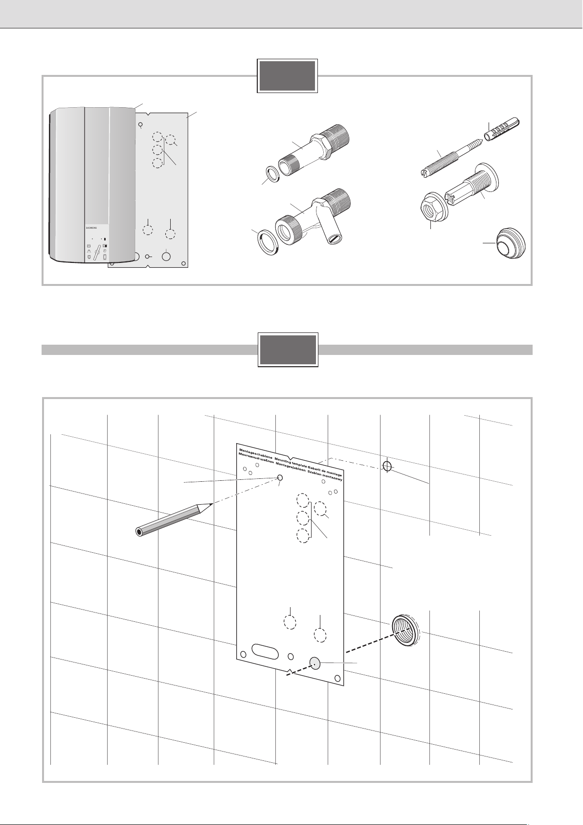
Lieferumfang
1 Durchlauferhitzer
2 Montageschablone
3 Auslaufstutzen für Warmwasser
4 Dichtung, rot Ø 15 mm
5 Zulaufstutzen für Kaltwasser
6 Dichtung, Ø 24 mm
7 Montageschraube
8 Dübel
9 Befestigungsmutter
10 Gewindebuchse
11 Leitungstülle
Im Folgenden wird die Befestigung mit der Montageschraube
beschrieben.
Befestigungspunkt anzeichnen und Öffnung zur Kabeleinführung auswählen (Bild A)
Achtung!
Vergewissern Sie sich, dass das elektrische
Anschlusskabel spannungsfrei ist!
■ Öffnung 3 der Montageschablone über den Kaltwasser-
zulauf legen.
■ Günstigste Öffnung für die Kabeleinführung auswählen:
Das elektrische Anschlusskabel darf nur durch eine der
sechs Öffnungen 14.. geführt werden. Wird es durch eine
der unteren Öffnungen 14a in den Durchlauferhitzer eingeführt, kann die Zwischenklemme BZ 45Z20 (Sonderzu-
behör) verwendet werden.
■ Befestigungspunkt 12 für die Montageschraube anzeichnen.
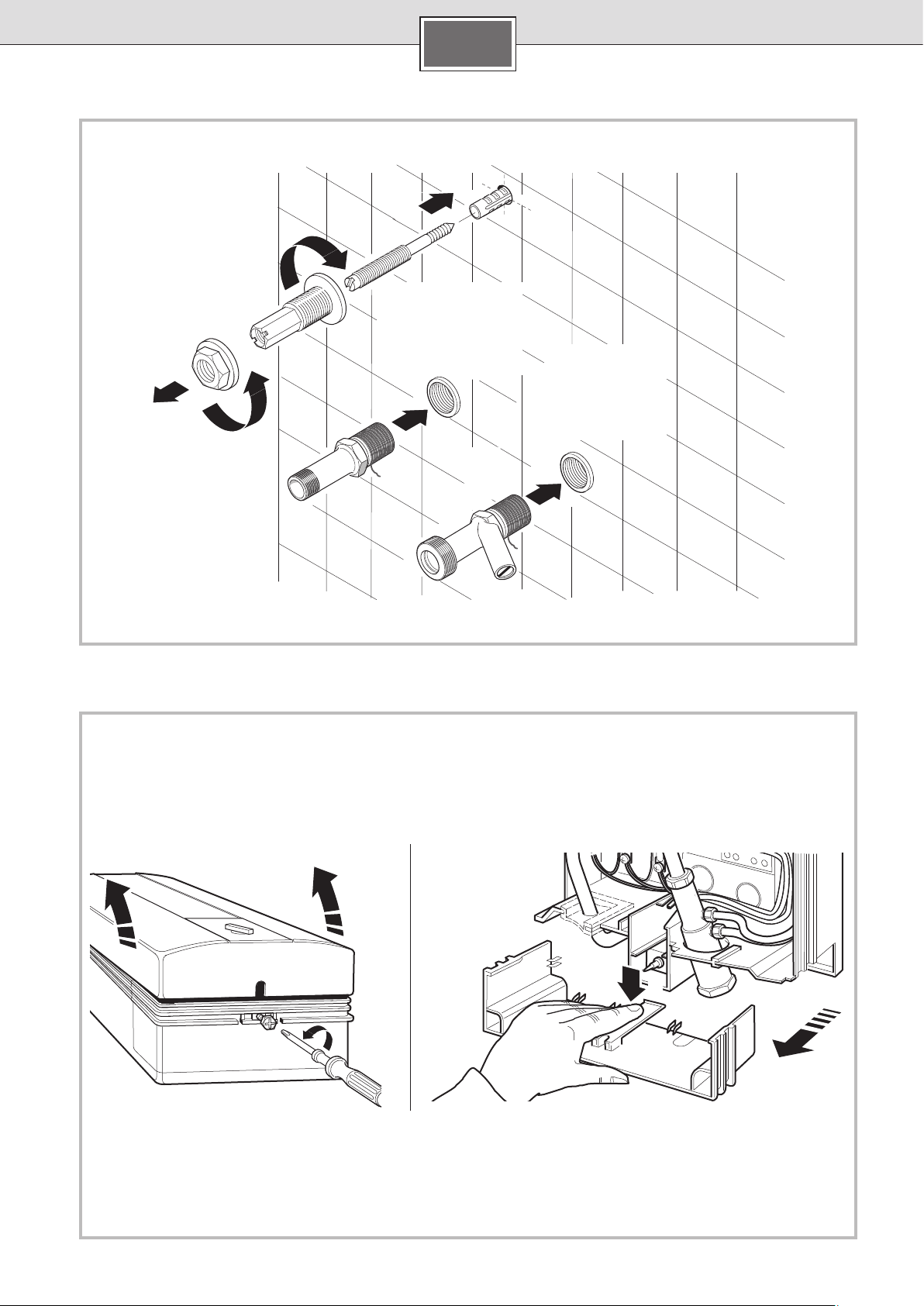
Montageschraube anbringen und Wasserstutzen
einschrauben (Bild B)
3
Page 4

de
Gerät öffnen (Bild C)
Öffnungen in der Rückwand für die Montageschraube
und die Kabeleinführung ausbrechen
Achtung: Um das Gerät zu befestigen, dürfen Sie nur die
vorgesehenen Öffnungen an der Gehäuserückwand ausbrechen. Ausgebrochene, aber unbenutzte Öffnungen müssen
Sie wasserdicht verschließen.
Kabel einführen (Bild D)
■ Leitungstülle 11 auf das Anschlusskabel schieben.
2
Hinweis: Bei einem Leiterquerschnitt von 16 mm
tungstülle nicht verwenden. Das Gerät muss dann wandbündig montiert werden.
Achtung: Ohne Leitungstülle besteht bei
DH18100/21100/24100 nur ein Spritzwasserschutz (IP 24).
■ Das Gerät auf das Anschlusskabel setzen.
■ Leitungstülle in die Gehäuserückwand eindrücken. Darauf
achten, dass die Dichtlippen an der Leitungseinführung
rundum anliegen.
■ Das Gerät auf die Gewindebuchse 8 setzen und mit Mut-
ter 9 verschrauben.
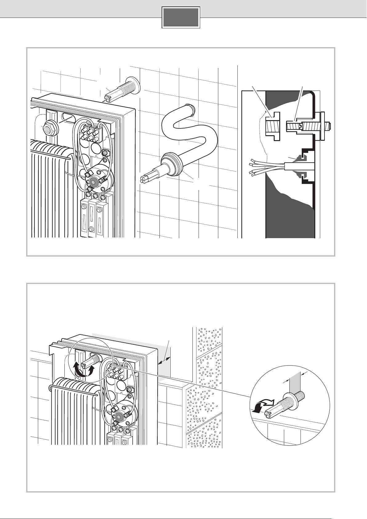
Wandunebenheiten ausgleichen (Bild E)
III.
Wasseranschluss
■ Mit der Feststellschraube 15 kann der Wasseranschluss
um ± 10 mm vertikal ausgerichtet werden.
■ Rohrbogen „warm“ an den Warmwasseranschluss anpas-
sen. Der Anschlusswinkel „kalt“ darf dabei nicht verbo-
gen werden.
Achtung: Darauf achten, dass ein Abstand von min. 6 mm zu
den stromführenden Teilen vorhanden ist.
■ Wasseranschlüsse verschrauben und Befestigungsmutter
an der Montageschraube festziehen.
Dichtheit prüfen und Gerät durchspülen:
■ Warmwasserhahn öffnen.
■ Alle Rohrverschraubungen auf Dichtheit prüfen.
die Lei-
Installationshinweis
■ Die Installation nicht-steckerfertiger Geräte ist vom jewei-
ligen Netzbetreiber oder von einem eingetragenen Fachbetrieb vorzunehmen, der Ihnen auch bei der Einholung
der Zustimmung des jeweiligen Netzbetreibers fur die
Installation des Gerätes behilflich ist.
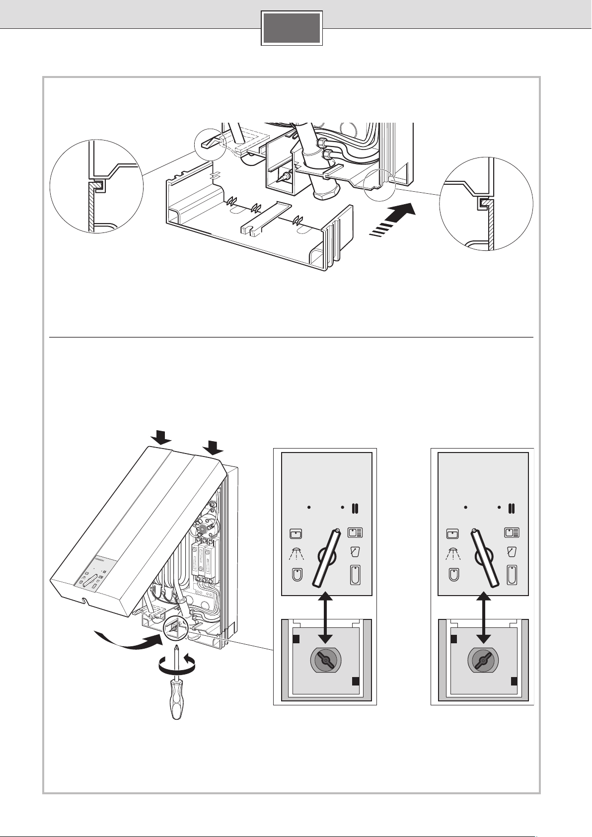
V.
Gerät schließen
■ Wenn Sie den Gehäusedeckel aufsetzen, achten Sie
auf die richtige Zuordnung von Schalterstellung und
Schalterachse.
VI.
Inbetriebnahme
Das Gerät stimmt mit IEC 61000-3-12 überein.
■ Sicherungen für den Durchlauferhitzer in der Hausinstalla-
tion einschalten.
■ Stufe II am Gerät einstellen und Wassertemperatur
überprüfen.
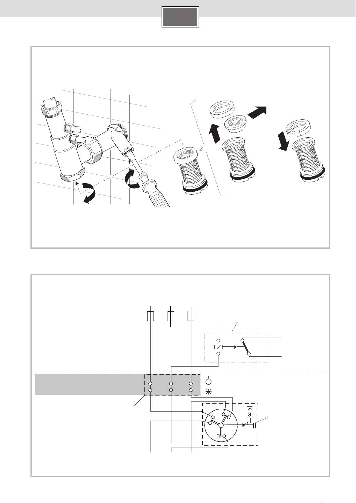
Bei niedrigem Wasserleitungsdruck
■ Öffnen Sie mehrere Kaltwasserhähne und prüfen dann,
ob sich die Heizung einschaltet. Schaltet sich die Heizung
nicht ein, entfernen Sie den Durchflussbegrenzer (Bild A).
■ Erklären Sie dem Benutzer das Gerät, und übergeben Sie
ihm bitte die Gebrauchsanweisung.
Vorrangschaltung für die Kombination mit Elektrospeicher-Heizgeräten (Bild B)
Für diesen Betrieb ist ein Vorrangschalter in die Phasenleitung L2 des Gerätes zu schalten. Er wird auf der Zähler- bzw.
Verteilertafel montiert.
a, b Steuerleitung des Elektrizitätswerkes zum Spulen-
eingang des Aufladeschutzes
f1 Sicherheits-Temperaturbegrenzer mit
Netzanschlussklemmen
f3 Vorrangschalter (Stromrelais)
l1 Netzanschlussklemme (nur bei 21-kW- und
24-kW-Gerät)
IV.
Elektroanschluss
■ Der Elektroanschluss 400 V 3 ~ darf grundsätzlich erst
nach dem Wasseranschluss erfolgen. Er ist entsprechend
dem Schaltbild auf der Innenseite der Abdeckhaube
auszuführen.
■ Zur Erfüllung der einschlägigen Sicherheitsvorschriften
muss installationsseitig eine allpolige Trennvorrichtung
vorhanden sein. Die Kontaktöffnung muss mindestens
3 mm betragen.
■ Wird das elektrische Anschlusskabel durch die unteren
Öffnungen 14a in den Durchlauferhitzer geführt, kann die
Zwischenklemme BZ 45Z20 (Sonderzubehör) verwendet
werden!
■ Die Leitungen dürfen den Auslöseknopf A des Sicherheits-
temperaturbegrenzers nicht in seiner Funktion behindern.
4
Page 5
de
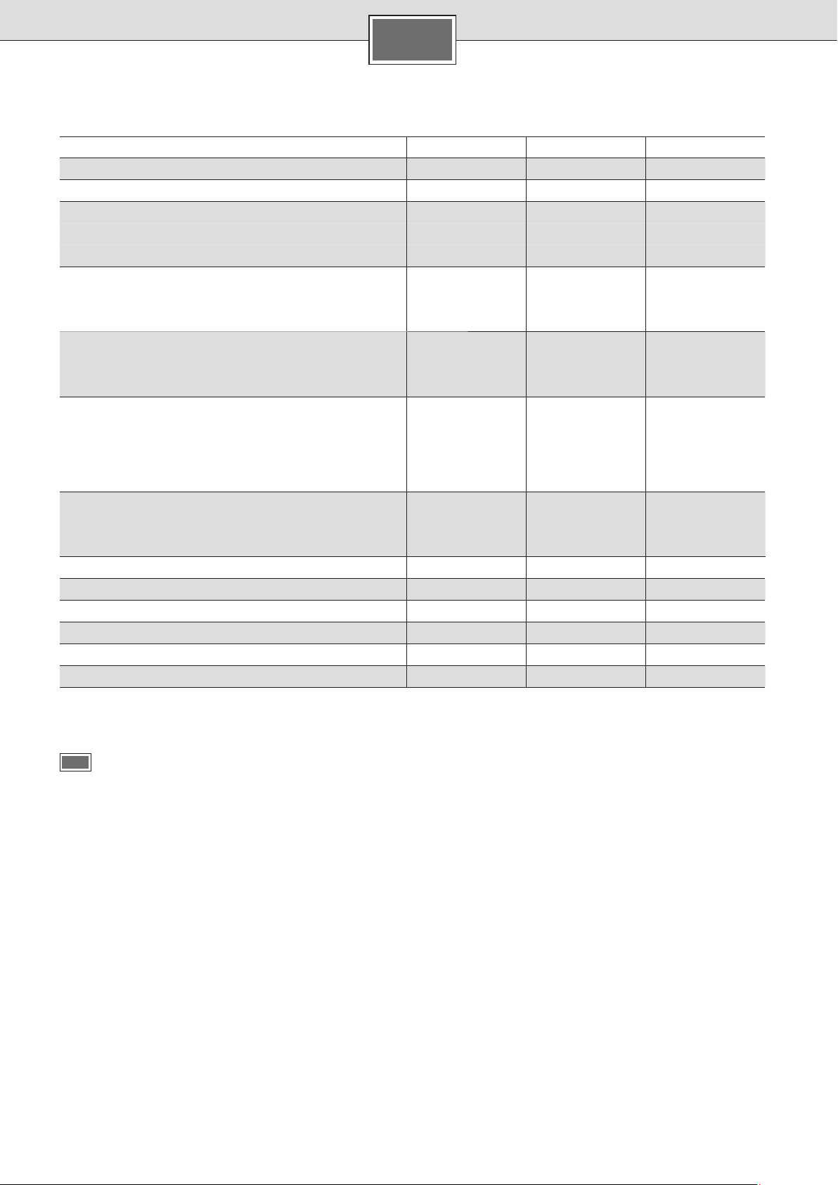
Technische Daten
DH18100 DH21100 DH24100
Nennleistung [kW]
Nennspannung
Heizleistung Sparstellung e [kW]
1. Stufe 6 7 8
2. Stufe 12 14 16
Heizleistung Starkheizung II [kW]
1. Stufe 9 10,5 12
2. Stufe 18 21 24
Einschaltpunkt [l/min]
1. Stufe 4,0 4,5 5,0
2. Stufe 5,0 5,8 6,6
Mischwasser [l/min] bei Nennleistung
von ca. 38 °C 9,8 11,5 13,1
von ca. 50 °C
(Zulauftemperatur 12 °C)
Mindestfließdruck am Gerät* [MPa (bar)]
mit Durchflussbegrenzer 0,6 (6) 0,8 (8) 0,9 (9)
ohne Durchflussbegrenzer 0,4 (4) 0,5 (5) 0,6 (6)
Energieeffizienzklasse
Lastprofil
Jahresenergieverbrauch [kWh]
Täglicher Stromverbrauch [kWh]
Schallleistungspegel [dB]
Warmwasserbereitungs-Energieeffizienz [%]
* Hierzu kommt noch der Druckabfall an der Mischbatterie.
18 21 24
400 V 3 ~ 400 V 3 ~ 400 V 3 ~
6,7 7,8 9,0
BBB
SSS
495 497 501
2,301 2,313 2,337
15 15 15
37,2 37,1 36,8
VII.
Abmessungen
Sonderzubehör
■ Rohrbausatz BZ 45K24: Zur Verwendung des Durchlauf-
erhitzers als Untertischgerät.
■ Zwischenklemme BZ 45Z20: Wird benötigt, wenn die
elektrische Anschlussleitung durch die untere Leitungseinführung 14a eingeführt wird.
■ Vorrangschalter (Lastabwurfrelais) BZ 45L21:
für den Betrieb mit Vorrangschaltung
■ Montageset BZ 45K24: für Aufputzinstallation
■ Gekürzte, und hinten verschlossene Anschlussstutzen für
den Wasseranschluss von unten (z. B. Kaltwasseranschluss
über eine untergebaute Armatur):
Kniestück „kalt“ (rechts) Bestell-Nr. 056169
Kniestück „warm“ (links) Bestell-Nr. 255568
5
Page 6
de
Gebrauchsanleitung
Bitte die ausführlichen Sicherheitshinweise am Anfang
dieser Anleitung durchlesen und beachten!
■ Wichtig: Das Gerät niemals Frost aussetzen!
Stromschlaggefahr!
Schalten Sie im Fehlerfall sofort die Netzspannung
ab!
■ Bei einer Undichtigkeit am Gerät sofort die Kaltwasser-
zuleitung schließen.
Gerät kennenlernen
Der Durchlauferhitzer erwärmt das Wasser, während es durch
das Gerät fließt. Nur in dieser Zeit verbraucht das Gerät Strom.
Dieses Gerät kann auch mehrere Wasser-Entnahmestellen
mit warmem Wasser versorgen. Es sollte nahe an der Entnahmestelle montiert werden, die Sie am meisten benutzen.
Dadurch sparen Sie Energie.
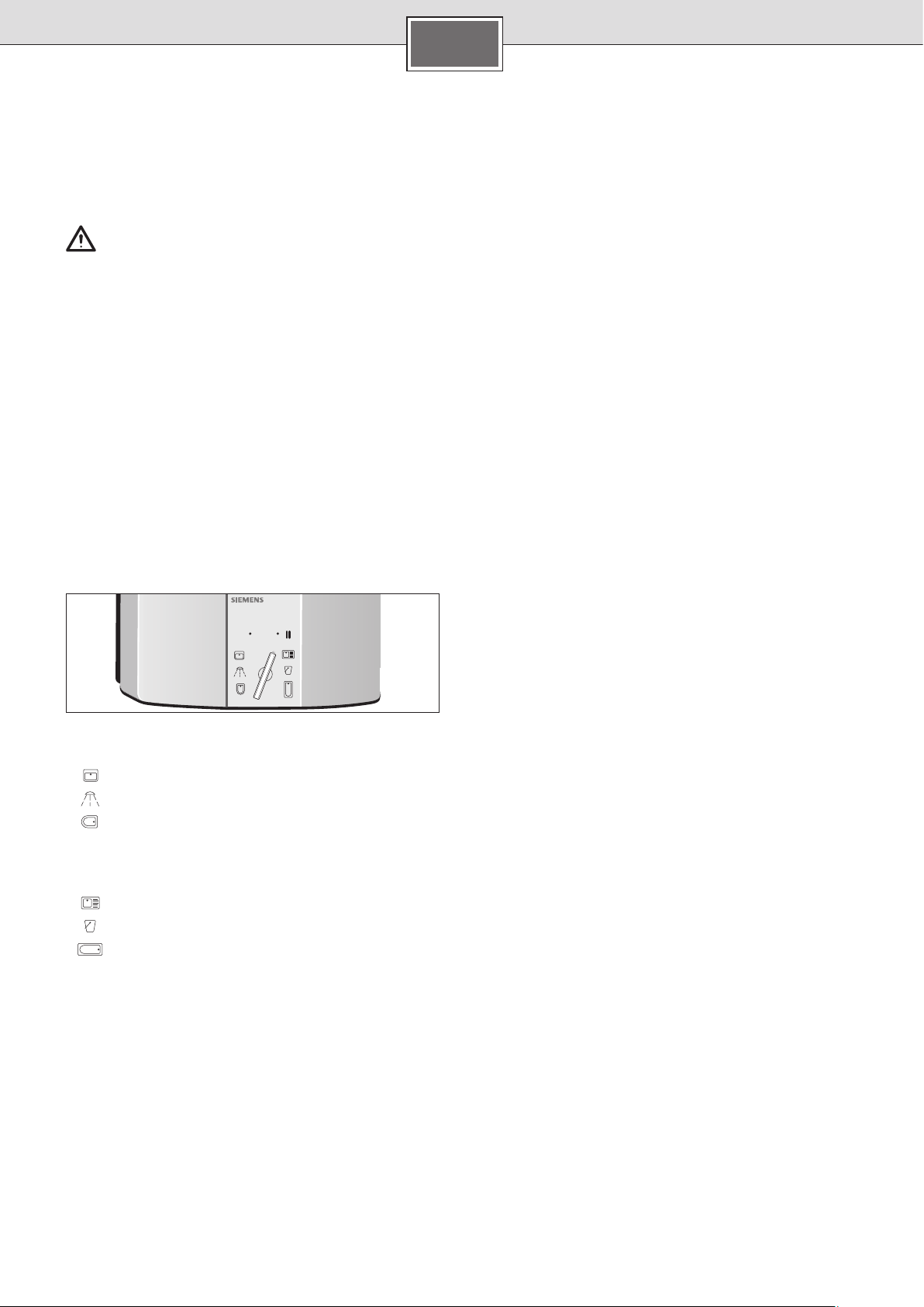
Gerät bedienen
Ihr Durchlauferhitzer hat zwei Stufen:
e Sparstufe – zwei Drittel Leistung
II Starkheizung – volle Leistung
automatic
e
Stufe e ist die ideale Einstellung für:
Waschbecken
Dusche
Bidet
Stufe II benutzen Sie für hohe Temperaturen oder große
Wassermengen, z.B.
Geschirrspülen
Putzen
Wannenbad
Wenn Sie eine Thermostatbatterie verwenden, stellen Sie auf
Stufe II.
1. Gewünschte Stufe e oder II einstellen.
2. Warmwasserhahn öffnen.
Der Durchlauferhitzer schaltet sich ein und erhitzt das Wasser, während es durch das Gerät fließt.
Er schaltet sich wieder aus, wenn Sie den Wasserhahn
schließen.
Wassertemperatur erhöhen
Bei ganz geöffnetem Wasserhahn reicht unter Umständen
die Leistung des Gerätes nicht aus, das Wasser auf die gewünschte Temperatur zu erhitzen.
■ Wasserhahn etwas schließen. Das Wasser fließt langsamer
durch das Gerät und wird heißer.
Wassertemperatur senken
■ Kaltwasser zumischen.
Bedienungshinweis
Bei nur wenig geöffnetem Warmwasserhahn arbeitet der
Durchlauferhitzer in beiden vorgewählten Stufen (e, II) mit
halber Leistung.
Bei ganz geöffnetem Warmwasserhahn arbeitet das Gerät
mit voller, vorgewählter Leistung.
Energie sparen
■ Benutzen Sie möglichst oft die Sparstufe „e“.
Sie nutzen die elektrische Energie besonders gut aus, wenn
Sie bei Beendigung der Warmwasserentnahme Folgendes
beachten:
– Durch langsames Schließen des Warmwasserhahnes wird
die Restwärme des Durchlauferhitzers genutzt.
– Sie vermeiden damit auch, dass bei erneuter Warmwasser-
entnahme innerhalb der nächsten Minuten die Wassertemperatur kurzzeitig höher ist als vorgewählt.
Vorteilhaft ist die Verwendung von Thermostatbatterien, da
dadurch besonders gleichmäßige Warmwassertemperaturen
erreicht werden.
Die Thermostatbatterie muss für hydraulisch gesteuerte
Durchlauferhitzer geeignet sein.
Winterbetrieb
Hinweis: Im Winter kann es vorkommen, dass die Zulauf-
temperatur des Wassers sinkt und dadurch die gewünschte
Auslauftemperatur nicht mehr erreicht wird.
■ Um diese Temperaturabsenkung auszugleichen, bitte die
Wassermenge am Wasserhahn so weit reduzieren, bis die
gewünschte Warmwassertemperatur erreicht wird.
Reinigung
■ Das Gerät nur feucht abwischen. Verwenden Sie keine
scharfen oder scheuernden Reinigungsmittel.
Hinweis: Das Gerät muss normalerweise nicht entkalkt werden. Bei extrem hartem Wasser und häufigem Zapfen von
sehr heißem Wasser kann das Gerät aber verkalken. Wenden
Sie sich an unseren Kundendienst.
6
Page 7

de
Eine Störung, was tun?
Achtung!
Reparaturen dürfen nur vom Fachmann durchgeführt werden. Sie setzen sich großer Gefahr aus,
wenn das Gerät unsachgemäß repariert wird.
Funktioniert Ihr Gerät nicht wie gewünscht, so liegt es oft
nur an einer Kleinigkeit. Bitte prüfen Sie, ob aufgrund folgender Hinweise die Störung selbst behoben werden kann.
Sie vermeiden dadurch die Kosten für einen unnötigen
Kundendiensteinsatz.
Das Wasser erwärmt sich nicht oder es fließt zu wenig
Wasser:
■ Die Sicherung in der Hausinstallation überprüfen.
■ Druckabfall im Wasserleitungsnetz. Bei geringem Druck
schaltet sich das Gerät nicht ein.
■ Das Sieb am Wasserhahn oder am Brausekopf ist ver-
stopft. Sieb abschrauben und reinigen oder entkalken.
■ Das Eckregulierventil ist verstopft. Warmwasserhahn ganz
öffnen und Eckregulierventil mehrmals auf- und zudrehen. Anschließend das Sieb am Wasserhahn reinigen.
■ Das Gerät muss entkalkt werden. Rufen Sie bitte einen
Fachmann.
Kundendienst
Wenn Sie den Kundendienst anfordern, geben Sie bitte die
E-Nummer und die FD-Nummer Ihres Gerätes an.
Sie finden die Nummern an der Unterseite des
Durchlauferhitzers.
Entsorgung
Dieses Gerät ist entsprechend der europäischen
Richtlinie 2012/19/EU über Elektro- und Elektronikaltgeräte (waste electrical and elec tronic equipment – WEEE) gekennzeichnet.
Die Richtlinie gibt den Rahmen für eine EU-weit
gültige Rücknahme und Verwertung der Alt geräte
vor.
Über aktuelle Entsorgungswege bitte beim Fachhändler informieren.
Das Gerät schaltet während der Wasserentnahme ab, die
Wassertemperatur sinkt:
■ Im Warmwasserhahn muss eine nicht quellende Dichtung
eingesetzt werden.
Wenn Sie die Störung nicht beheben können, schalten Sie
die Sicherung in der Hausinstallation aus. Rufen Sie einen
Fachmann.
Änderungen vorbehalten.
7
Page 8
de
09/14
8
Page 9

en
Safety information
This appliance is intended for domestic use
or for household-based, non-commercial
applications. Household-based applications
include, e.g. usage in employees catering
facilities for shops, offices, agricultural and
other commercial operations, as well as
usage by guests of guest houses, small hotels
and similar residential establishments.
■ Install and operate the appliance as de-
scribed in the text and illustrations. We do
not accept liability for damage resulting
from failure to heed these instructions.
■ This appliance is intended for use up to an
altitude of 2000 m above sea level.
■ The appliance may only be installed and
stored in a frost-free room (due to residual
water).
Risk of electric shock!
Switch off the mains voltage supply
immediately if a fault occurs.
Immediately shut off the cold water
supply to the appliance should it leak.
■ The continuous-flow heater may only be
connected and put into operation by a
qualified professional.
■ In order to avoid potential sources of
danger, repairs and maintenance may
only be undertaken by a suitably qualified specialist.
■ Never open the appliance without discon-
necting the power supply beforehand.
■ The statutory regulations of the respective
country, as well as those of the local electricity and water suppliers, must be adhered to.
■ The continuous-flow heater is a Class I
appliance and must be connected to the
protective earth.
■ The appliance must be permanently
connected to installed pipes. The conduc-
tor cross-section must comply with the
installed appliance power.
■ Caution: Earthed water pipes may give the
appearance of a connected protective earth.
■ To guarantee compliance to relevant safety
regulations, an all-pole separator must
be fitted during installation. The contact
opening must be at least 3 mm.
■ The continuous-flow heater is only suitable
for closed (pressurised) operation.
■ The tap and outlet fittings must be approved
for operation with closed (pressurised) continuous-flow heater systems.
■ Only connect the continuous-flow heater
to a cold water line. A non-return valve
must NOT be connected to the cold water.
■ Do not use plastic pipes. Steel or copper
pipes are suitable for the cold-water supply. Insulated copper pipes are particularly
suitable for the hot-water pipes.
■ The appliance should be installed
close to the tap that is used the most
frequently.
■ Disconnect the electrical connection cable
from the supply and shut off the water
supply before connecting the appliance!
■ Connect the water supply and then
connect the electrical supply.
■ Only make the openings which are re-
quired for installation on the rear of the
appliance. If the appliance is reinstalled,
the unused openings must be provided
with watertight sealing.
■ Do not touch electrically live parts after
installation.
■ The appliance should be disconnected
from the electrical mains supply when
working on the water supply. After service
work is complete, proceed as during the
first-time appliance start-up.
■ No changes may be made to the appliance.
■ The appliance may only be used for heat-
ing drinking water for household use.
■ This appliance can be used by children aged
8 years and older as well as by persons with
diminished bodily, sensory or mental perception, or those who lack knowledge or experience, if they are monitored or have received
instruction concerning use and comprehend
the possible dangers that can result. Chil-
dren may not play with the appliance. Cleaning and maintenance by the user may not
be performed by unsupervised children.
■ Keep children away from the appliance.
■ Please monitor children to ensure that they
do not play with the appliance.
9
Page 10
en
■ The mixer and the warm water pipe may
be hot. Please inform and instruct children
appropriately.
■ Do not use aggressive or abrasive cleaning
detergents!
Congratulations on purchasing this Siemens appliance. You
have acquired a top-quality product, which will give you a lot
of enjoyment.
Please read this installation and operating instruction
manual carefully, then act accordingly! Store for future
reference.
Installation instructions
Install the continuous-flow heater as described in the
illustrated section. Observe the instructions in the text.
The illustrations can be found in the centre of the instruction
manual.
Installation
■ Do not use a steam cleaner.
■ The appliance is only to be descaled by a
suitably qualified specialist.
The following describes the installation procedure using the
mounting bolt.
Marking the point for mounting the heater and selecting
the opening for the connecting cable (Fig. A)
Important!
Make sure that the connecting cable is isolated
from the mains electricity supply!
■ Place hole 3 in the mounting template over the cold-water
inlet.
■ Select the most suitable hole through which the con-
necting cable is be fed. The connecting cable must pass
through one of the six holes marked 14... Terminal
BZ 45Z20 can be used if the cable is fed into the water
heater through one of the bottom holes marked 14a.
■ Mark the point 12 at which the mounting bolt is to be
inserted.
I.
List of items supplied
1 Continuous-flow heater
2 Installation template
3 Connection piece for hot water
4 Washer, red Ø 15 mm
5 Connection piece for cold water
6 Washer, Ø 24 mm
7 Mounting bolt
8 Wall plug
9 Securing nut
10 Threaded bushing
11 Cable grommet
II.
Wall mounting
There are two ways in which the continuous-flow heater can
be mounted on the wall:
– Using the mounting bolt. Unevenness in the wall up to a
depth of 25 mm can be compensated for.
– Making use of the holes that were drilled for the old heater:
Use the mounting template to establish whether the existing holes line up properly.
Fitting the mounting bolt and attaching the pipe
connecting pieces (Fig. B)
Open up the heater (Fig. C)
Punching out the holes at the rear of the heater for the
mounting bolt and the connecting cable
Important: When mounting the appliance, only the holes
actually required should be punched out. Any other holes
that are not going to be used must be sealed watertight.
Inserting the connecting cable (Fig. D)
■ Push the grommet 11 over the end of the connecting
cable.
Note: Do not use the grommet for a cable with a cross-section of 16 mm
with the wall.
Attention: Without a grommet, the DH18100/21100/24100
is splashproof only (IP 24).
■ Place the heater over the connecting cable.
■ Press the grommet into the hole in the rear wall of the
heater through which the cable should be fed. Ensure that
the edges of the grommet are flush with the hole all the
way round.
■ Fit the heater onto the threaded bushing 8 and secure it
in place with the nut 9.
2
. The appliance must then be installed flush
10
Compensating for unevenness in the wall (Fig. E)
Page 11

en
III.
Water connection
■ Using the locking screw 15, the water connection can be
aligned by ± 10 mm vertically.
■ Adapt the bend in the “hot” pipe so that it lines up with
the hot-water outlet. In doing so, make sure that the
“cold” elbow connection is not bent.
Attention: Ensure that a distance of at least 6 mm is main-
tained to live parts of the heater.
■ Connect the water outlet and inlet and tighten the secur-
ing nut on the mounting bolt.
Checking for leaks and flushing the heater:
■ Turn on the hot-water tap.
■ Check that all pipe joints are properly sealed.
IV.
Electrical connection
■ As a matter of principle, the water connections must be
completed first of all before the heater is connected to
the electricity supply (400 V AC, 3-phase). The appliance
should be wired up according to the circuit diagram on
the inside of the cover.
■ To guarantee compliance to relevant safety regulations,
an all-pole separator must be fitted during installation.
The contact opening must be at least 3 mm.
■ Terminal BZ 45Z20 (special accessories) can be used if the
connecting cable is fed into the heater via one of the bottom holes 14a!
■ The wires must not interfere with the operation of release
button A on the safety temperature limiter.
VI.
Startup
The device is compliant to IEC 61000-3-12.
■ Switch on via the water heater fuses in the domestic
wiring.
■ Select Setting II on the appliance and check the water
temperature.
At a low water-pipe pressure
■ Turn on additional cold-water taps and check whether the
heater switches on. Remove the continuous-flow heater if
the heater does not switch on (Fig. A).
■ Explain the appliance to the user and please give him the
operating instructions.
Priority switch for combination with electric storage
heaters (Fig. B)
If the heater is going to be operated in this way, a priority
switch must be connected into the line connecting the L2
phase to the appliance. It should be mounted on the meter
or distribution panel.
a, b Control line for the electricity supply company con-
nected to the coil input on the charging contactor
f1 Safety temperature limiter with mains terminals
f3 Priority switch (current relay)
l1 Mains terminal (only on 21 kW and 24 kW appliances)
Installation note
■ The installation of non plug-in ready appliances must be
undertaken by the respective utility operator or by a qualified specialist company, who can also assist you when
you are requesting the approval of the utility company for
installation of the appliance.
V.
Mounting the cover onto the heater
■ When you mount the cover onto the heater, ensure that the
switch knob and the switch spindle are correctly aligned.
11
Page 12

en
Specifications
DH18100 DH21100 DH24100
Rated power [kW]
Rated voltage
Heating capacity – economy setting e [kW]
1st stage 6 7 8
2nd stage 12 14 16
Heating capacity – intensive setting II [kW]
1st stage 9 10.5 12
2nd stage 18 21 24
Switch-on point [I/min]
1st stage 4.0 4.5 5.0
2nd stage 5.0 5.8 6.6
Mixed water [I/min] at rated power
approx. 38 °C 9.8 11.5 13.1
approx. 50 °C
(supply temperature 12 °C)
Minimum flow pressure of appliance* [MPa (bar)]
with flow limiter 0.6 (6) 0.8 (8) 0.9 (9)
without flow limiter 0.4 (4) 0.5 (5) 0.6 (6)
Energy efficiency class
Load profile
Annual energy consumption [kWh]
Daily energy consumption [kWh]
Sound power level [dB]
Hot water heating energy efficiency [%]
* The pressure loss on the mixer must also be added.
18 21 24
400 V 3 ~ 400 V 3 ~ 400 V 3 ~
–
6.7 7.8 9.0
BBB
SSS
495 497 501
2.301 2.313 2.337
15 15 15
37.2 37.1 36.8
VII.
Dimensions
Special accessories
■ BZ 45K24 Pipe set: for use of the continuous-flow heater
as an under sink appliance
■ Intermediate terminal block BZ 45Z20: Required when the
mains connecting cable is fed in through the bottom access hole 14a.
■ Priority switch (load shedding relay) BZ 45L21:
for operation with a priority circuit
■ Mounting kit BZ 45K24: for surface mount installation
■ Truncated connecting piece sealed at rear for water con-
nection from below (e. g. cold water connection via fitting
mounted below heater):
Elbow joint, “cold” (right) Order no. 056169
Elbow joint, “hot”, (left) Order no. 255568
12
Page 13

en
Operating instructions
Please read and observe the detailed safety instructions
at the start of these instructions!
■ Important: The appliance may never be exposed to frost!
Risk of electric shock!
Switch off the mains voltage supply immediately if
a fault occurs.
■ Immediately shut off the cold water supply to the appli-
ance should it leak.
Getting to know your appliance
The continuous-flow heater heats the water as it flows
through the appliance. The appliance only consumes power
during this period.
This appliance can supply hot water to taps in several different locations. It should be installed close to the tap that
is used the most frequently. This will enable you to reduce
energy consumption.
Operating the appliance
The continuous-flow heater has two power settings:
e Economy setting – two thirds power
II Intensive setting – full power
automatic
e
The e setting is ideal for:
Wash basin
Shower
Bidet
II setting should be used where a higher temperature or a
larger volume of water is required, e. g.
Dishwashing
Cleaning
Bath tub
If you are using a thermostat-controlled mixer tap, set the
heater to II.
1. Set the heater to either e or II, as required.
2. Turn on the hot-water tap.
The continuous-flow heater switches on automatically and
heats the water as it flows through the appliance.
The heater switches off again when you turn off the tap.
Increasing the water temperature
When the tap is turned on fully, it is possible that the heater
capacity is not sufficient to heat the water to the required
temperature.
■ Slightly close the hot-water tap. The water flows through
the appliance more slowly and reaches a higher temperature as a result.
Decreasing the water temperature
■ Mix with cold water.
Note about operation
When a hot-water tap is turned on by only a small amount,
the continuous-flow heater operates at half power regardless
of which setting (e, II) has been selected.
When a hot-water tap is turned on fully, the appliance operates at the maximum level of power that corresponds to
whichever setting has been selected.
Saving energy
■ Please use economy setting “e” as often as possible.
To minimise energy consumption when turning off the hot
water:
– Turn off the hot-water tap slowly in order to use the re-
sidual heat of the continuous-flow heater.
– This also prevents the water temperature from briefly
increasing above the preselected temperature if the hotwater tap is turned on again within the next few minutes.
To obtain particularly uniform hot-water temperatures, it is
recommended to use thermostat-controlled mixer taps.
The thermostat-controlled mixer tap must be suitable for hydraulically controlled continuous-flow heater.
Winter operation
Note: It is possible in winter that the supply temperature of
the water is reduced and the required outlet temperature is
no longer achieved.
■ In order to compensate for this temperature reduction,
please reduce the water quantity on the tap until the required water temperature is achieved.
Cleaning
■ Simply wipe the appliance with a damp cloth.
Do not use acidic or abrasive cleaning materials.
Notes: It is normally not necessary to descale the appliance.
However, extremely hard water and the frequent flows of
very hot water can cause the appliance to scale up. In this
case please contact our after-sales service.
13
Page 14

en
A fault, what to do?
Attention!
Repairs must only be carried out by an authorised
technician. Improper repairs can lead to risk of serious injury to the user.
If your appliance does not operate as required, it is often
due to a very minor problem. Please check whether you can
remedy the fault yourself by using the following guidelines.
You will save yourself the costs of an unnecessary visit by
customer service personnel.
The water does not heat up or not enough water flows
out of the tap:
■ Check the fuse in the fusebox.
■ Drop in pressure in the water mains. If the pressure is too
low, the appliance will not switch on.
■ The strainer on the tap or shower head is blocked.
Unscrew the strainer and either clean or descale it.
■ The corner valve is clogged. Turn on the hot-water tap
fully and open and close the corner valve several times.
Then clean the filter in the water tap.
■ The heater needs descaling. Arrange for a service engi-
neer to visit.
The continuous-flow heater switches off during the
drawing-off of water, resulting in a reduction in the
water temperature:
■ The washer inside the hot-water tap must be a non-swell-
ing type.
If you cannot resolve the problem yourself, switch off the
heater via the fuse in the domestic wiring. Arrange for a
service engineer to visit.
After-sales service
If you call the after-sales service for assistance, please specify
the E no. and FD no. of your appliance.
These numbers can be found on the underside of the continuous-flow heater.
Disposal
This appliance is labelled in accordance with European Directive 2012/19/EU concerning used electrical and electronic appliances (waste electrical
and electronic equipment – WEEE).
The guideline determines the framework for the
return and recycling of used appliances as applicable throughout the EU.
Please ask your specialist retailer about current
disposal facilities.
Guarantee
The guarantee conditions for this appliance are as defined by
our representative in the country in which it is sold.
Details regarding these conditions can be obtained from the
dealer from whom the appliance was purchased. The bill of
sale or receipt must be produced when making any claim
under the terms of this guarantee.
Subject to change without notice.
14
Page 15
Page 16
I.
automatic
e
Montageschablone Mounting template
1
Montagesjabloon Szablon montażowy
12
14a
13
Gabarit de montage
14
14a
14a
3
2
6
4
3
5
II.
9
8
7
10
11
A
12
12
14a
14a
14a
12
14
Kaltwasserzulauf
cold water supply
dopływ zimnej wody
soğuk su giriși
3
Page 17
B
II.
Warmwasser
warm water
ciepłej wody
sıcak su
Kaltwasser
cold water
zimnej wody
soğuk su
C
1.
2.
Page 18
D
II.
9
8
98
11
11
E
0 –25 mm
Variabler Wandabstand
adjusting distance from wall
zmiana odległości od ściany
değișken duvar mesafesi
0 –25 mm
Page 19

„warm“
1
3
5
L2
L3
L1
L1
L2
L3
“hot”
„ciepły“
“sıcak”
III.
15
„kalt“
“cold”
„zimnej“
“soğuk”
±10
90 –120 mm
IV.
18 kW 21 kW/24 kW
A14 a A
14 a
Page 20
V.
1.
e e
automatic
e
oder
or
dnie
veya
2.
3.
Page 21
A
VI.
1.
2. 3. 4.
B
L 1 L 2 L 3
f 3
a
b
nur bei 21-kW- und 24-kW-Gerät
only on 21 kW and 24 kW appliances
tylko w przypadku urządzeń 21 kW i 24 kW
yalnız 21
kW ve 24 kW’lık cihazla
l 1
L1
L2 L3
PE
2
3
4
5
1
6
f 1
Page 22

236
56
VII.
136
83
100
388
42
472
G ½ A
57
Page 23

pl
Zasady bezpieczeństwa
To urządzenie jest przeznaczone do stosowania w gospodarstwach domowych lub podobnych i nie nadaje się do użytku przemysłowego. Zastosowania zbliżone do gospodarstw
domowych obejmują m. in. wykorzystanie
w kuchniach pracowniczych w sklepach, biurach, zakładach rolniczych lub innych zakładach rzemieślniczych, oraz korzystanie przez
gości w pensjonatach, małych hotelach i innych placówkach mieszkaniowych.
■ Montować i obsługiwać urządzenie zgod-
nie ze wskazówkami w tekście i na ilustracjach. Nie przejmujemy żadnej odpowiedzialności za szkody, powstałe w wyniku
nieprzestrzegania tej instrukcji.
■ Urządzenie jest przeznaczone do użytko-
wania do wysokości 2 000 m nad poziomem morza.
■ Urządzenie instalować i przechowywać
w pomieszczeniach zabezpieczonych przed
mrozem (pozostałości wody).
Niebezpieczeństwo porażenia prądem!
W razie awarii natychmiast wyłączyć
zasilanie sieciowe.
W przypadku wystąpienia nieszczelności urządzenia natychmiast zamknąć
dopływ zimnej wody.
■ Podgrzewacz przepływowy może być
podłączany i uruchamiany wyłącznie
przez specjalistę.
■ Aby uniknąć zagrożeń, naprawy i prace
konserwacyjne mogą być przeprowadzane tylko przez specjalistę.
■ Nigdy nie otwierać urządzenia bez
uprzedniego odłączenia go od zasilania
energią elektryczną.
■ Należy przestrzegać przepisów ustawo-
wych danego kraju oraz wymagań lokalnego przedsiębiorstwa elektroenergetycznego i wodociągowego.
■ Podgrzewacz przepływowy jest urządze-
niem klasy zabezpieczenia I i musi być podłączany do przewodu ochronnego.
■ Urządzenie musi być trwale podłączone do
ułożonych na stałe rurociągów. Przekrój
przewodów musi odpowiadać zainstalowanej mocy.
■ Uwaga: uziemione przewody wodne mogą
symulować istnienie przewodu ochronnego.
■ Dla spełnienia obowiązujących przepisów
bezpieczeństwa instalacja musi być wyposażona w rozłącznik, odcinający wszystkie
bieguny zasilania. Rozwarcie styków musi
wynosić co najmniej 3 mm.
■ Podgrzewacz przepływowy jest przezna-
czony tylko do pracy w systemie zamkniętym (ciśnieniowym).
■ Armatury muszą być dopuszczone do pra-
cy z zamkniętymi (ciśnieniowymi) podgrzewaczami przepływowymi.
■ Podgrzewacz przepływowy należy pod-
łączać wyłącznie do przewodu zimnej
wody. Na przewodzie doprowadzającym
zimną wodę nie wolno instalować zaworu
zwrotnego.
■ Nie wolno stosować rur z tworzyw sztucz-
nych. Jako przewody doprowadzające
zimnej wody stosować rury stalowe albo
miedziane. Jako przewody ciepłej wody
zaleca się szczególnie rury miedziane
z termoizolacją.
■ Urządzenie powinno być zamontowane
w pobliżu najczęściej używanego zaworu
czerpalnego.
■ Przed rozpoczęciem montażu należy
odłączyć elektryczny przewód zasilający
od napięcia i zamknąć przewód wodny!
■ Podłączanie elektryczne należy wykony-
wać dopiero po podłączeniu wody.
■ W ściance tylnej wykonywać tylko te otwo-
ry, które są potrzebne do montażu. Przy
ponownym montażu należy wodoszczelnie
zatkać nieużywane otwory.
■ Po zakończeniu montażu nie może istnieć
możliwość dotknięcia elementów pod
napięciem.
■ Podczas wykonywania prac przy instalacji
wodociągowej należy odłączyć urządzenie
od sieci. Po zakończeniu prac należy postępować zgodnie z opisem w punkcie Pierwsze uruchomienie.
■ Nie dokonywać żadnych zmian urządzenia.
■ Urządzenie może być używane wyłącznie
do nagrzewania wody pitnej w gospodarstwach domowych.
15
Page 24

pl
■ Z urządzenia mogą korzystać dzieci w wie-
ku od lat 8 oraz osoby z ograniczonymi
zdolnościami fizycznymi, sensorycznymi lub
psychicznymi oraz bez doświadczenia lub
wiedzy, jeśli będą nadzorowane lub zostaną zapoznane ze sposobem bezpiecznego
użytkowania urządzenia oraz poinformowane o zagrożeniach związanych z urządzeniem. Dzieci nie mogą wykorzystywać
urządzenia do zabawy. Nie wolno powierzać dzieciom bez nadzoru prac związanych
z czyszczeniem i konserwacją urządzenia.
■ Nie dopuszczać dzieci do urządzenia.
Serdecznie gratulujemy nabycia urządzenia produkcji firmy
Siemens. Nabyli Państwo wysokiej jakości urządzenie, które
na pewno przyniesie Państwu wiele pożytku.
Prosimy uważnie przeczytać niniejszą instrukcję montażu
obsługi i stosować się do niej! Instrukcję należy zachować
do późniejszego wykorzystania!
Instrukcja montażu
■ Nadzorować dzieci, aby zapobiec bawieniu
się urządzeniem.
■ Bateria i rura ciepłej wody mogą się bardzo
nagrzewać. Pouczyć o tym dzieci.
■ Nie używać środków do szorowania lub
rozpuszczalników.
■ Nie używać myjek parowych.
■ Usuwanie osadu kamienia z urządzenia
może być dokonywane wyłącznie przez
specjalistów.
II.
Montaż na ścianie
Podgrzewacz przepływowy można zamocować na ścianie na
dwa sposoby:
– Za pomocą wkrętu montażowego: Nierówności ściany do
25 mm dają się wyrównać.
– Wykorzystując otwory mocowania pozostałe po starym
urządzeniu: Sprawdzić za pomocą szablonu montażowego, czy otwory mocowania pozostałe po starym urządzeniu pasują do nowego urządzenia.
Montaż podgrzewacza przepływowego należy przeprowadzać zgodnie z opisem w ilustrowanej części. Należy przestrzegać wskazówek w tekście.
Strony z ilustracjami znajdują się w środku instrukcji.
Montaż
I.
Zakres dostawy
1 Przepływowy podgrzewacz wody
2 Szablon montażowy
3 Króciec wylotowy przyłącza ciepłej wody
4 Uszczelka, czerwona Ø 15 mm
5 Króciec dopływowy przyłącza zimnej wody
6 Uszczelka, Ø 24 mm
7 Wkręt montażowy
8 Kołek rozporowy
9 Nakrętka mocująca
10 Tuleja gwintowana
11 Tulejka ochronna przewodu elektrycznego
Poniżej opisany jest sposób mocowania za pomocą wkrętu
montażowego.
Zaznaczyć punkt mocowania i wybrać otwór wejścia przewodu elektrycznego (rysunek A)
Uwaga!
Upewnić się, czy elektryczny przewód zasilający nie
znajduje się pod napięciem!
■ Przyłożyć otwór 3 szablonu montażowego na doprowa-
dzenie zimnej wody.
■ Wybrać stosowany otwór wejścia przewodu elektryczne-
go. Przewód elektryczny można wprowadzić tylko przez
jeden z sześciu otworów 14... Jeśli przewód elektryczny
wprowadza się do podgrzewacza przepływowego przez
jeden z dolnych otworów 14a, można zastosować kostkę
zaciskową pośrednią BZ 45Z20.
■ Zaznaczyć punkt mocowania 12 na wkręt montażowy.
Wkręcić wkręt montażowy i króciec wodny (rysunek B)
Otworzyć urządzenie (rysunek C)
W tylnej ściance wyłamać otwór na wkręt montażowy
i otwór wejścia przewodu elektrycznego
Uwaga: W celu zamocowania urządzenia wolno wyłamać
w tylnej ściance obudowy tylko otwory na to przeznaczone.
Wyłamane, ale niewykorzystane otwory należy wodoszczelnie zaślepić.
16
Page 25

pl
Wprowadzić przewód elektryczny (rysunek D)
■ Tulejkę ochronną 11 nasunąć na przewód elektryczny.
2
Wskazówka: Do przewodu o przekroju 16 mm
tulejki ochronnej. Urządzenie musi wtedy zostać zamontowane na równi ze ścianą.
Uwaga: Bez nakładki na przewód urządzenie
DH18100/21100/24100 jest zabezpieczone tylko przed
rozpryskami wody (IP 24).
■ Urządzenie nasunąć na przewód elektryczny.
■ Tulejkę ochronną wcisnąć w tylną ściankę obudowy urzą-
dzenia. Zwrócić uwagę, aby kołnierz uszczelki przylegał
dokładnie wokół przewodu elektrycznego.
■ Założyć urządzenie na tulejkę gwintowaną 8 i przykręcić
nakrętką 9.
Kompensacja nierówności ściany (rysunek E)
III.
Przyłącze wody
■ Za pomocą śruby ustalającej 15 można zmienić położenie
przyłącza wodnego w pionie o ± 10 mm.
■ Łuk rurowy „ciepły“ dopasować odpowiednio do przyłącza
ciepłej wody. Nie wolno giąć złączki kątowej „zimnej“.
Uwaga: Przy dopasowaniu koniecznie zwrócić uwagę, żeby
odległość do części znajdujących się pod napięciem wynosiła
minimum 6 mm.
■ Przykręcić przyłącza wodne i dokręcić nakrętkę mocującą
na wkręcie montażowym.
Sprawdzić szczelność i urządzenie przepłukać:
■ Otworzyć zawór ciepłej wody.
■ Sprawdzić szczelność wszystkich złączek rurowych.
IV.
Przyłącze elektryczne
■ Podłączenie elektryczne 400 V 3 ~ może nastąpić dopie-
ro po wykonaniu przyłączeń wodnych. Należy je wykonać
zgodnie ze schematem połączeń umieszczonym na wewnętrznej stronie pokrywy.
■ Dla spełnienia obowiązujących przepisów bezpieczeństwa
instalacja musi być wyposażona w rozłącznik, odcinający
wszystkie bieguny zasilania. Rozwarcie styków musi wynosić co najmniej 3 mm.
■ W przypadku wykorzystania jednego z dolnych otworów
wejścia przewodu elektrycznego 14a można zastosować
pośrednią kostkę zaciskową BZ 45Z20 (wyposażenie
dodatkowe)!
■ Przewód elektryczny musi być tak poprowadzony aby nie
utrudniał działania przycisku zwalniającego A zabezpie-
czającego ogranicznika temperatury.
nie stosować
Wskazówki instalacyjne
■ Instalacja urządzeń nie posiadających gotowego wtyku
sieciowego musi zostać wykonana przez operatora sieci
lub przez autoryzowany zakład specjalistyczny, który pomoże w uzyskaniu zezwolenia właściwego operatora sieci
na instalację tego urządzenia.
V.
Zamknąć urządzenie
■ Przy nakładaniu pokrywy obudowy urządzenia zwrócić
uwagę na właściwe przyporządkowanie wyłączników do
ich osi.
VI.
Uruchomienie
Urządzenie spełnia wymagania normy IEC 61000-3-12.
■ W domowej instalacji elektrycznej włączyć wyłączniki
bezpieczeństwa dla podgrzewacza przepływowego.
■ Nastawicę na urządzeniu stopienę ogrzewania II i spraw-
dzicę temperaturę wody.
Przy niskim cisęnieniu wody w sieci wodociągowej
■ Otworzyć kolejne zawory zimnej wody, a następnie spraw-
dzić, czy włączy się ogrzewanie. Jeżeli grzałka nie jest włączana, usunąć ogranicznik przepływu (rysunek A).
■ Proszę zaznajomić użytkownika z urządzeniem, wyjaśnić
zasadę jego działania i przekazać instrukcję obsługi.
Obwód priorytetowy dla kombinacji z akumula cyjnym
grzejnikiem elektrycznym (rysunek B)
W celu umożliwienia pracy z obwodem priory tetowym należy
zainstalować wyłącznik priory tetu (przekaźnik prądowy) na
przewodzie fazowym L2 urządzenia. Wyłącznik ten montuje
się na tablicy licznika, względnie tablicy rozdzielczej.
a, b Przewód sterujący zakładu energetycznego do wejścia
cewki stycznika
f1 Zabezpieczający ogranicznik temperatury z zaciskami
przyłączeniowymi przewodów zasilających
f3 Wyłącznik priorytetu (przekaźnik prądowy)
l1 Zaciski przyłączeniowe przewodów zasilających
(tylko w przypadku urządzeń 21 kW i 24 kW)
17
Page 26

pl
Dane techniczne
DH18100 DH21100 DH24100
Moc znamionowa [kW]
Napięcie znamionowe
Moc grzejna – nastawienie oszczędne e [kW]
1. stopień 6 7 8
2. stopień 12 14 16
Moc grzejna – podgrzewanie intensywne II [kW]
1. stopień 9 10,5 12
2. stopień 18 21 24
Punkt włączania [l/min]
1. stopień 4,0 4,5 5,0
2. stopień 5,0 5,8 6,6
Natężenie przepływu wody mieszanej
[l/min] przy mocy znamionowej
dla ok. 38 °C 9,8 11,5 13,1
dla ok. 50 °C
(temperatura wody dopływowej 12 °C)
Minimalne ciśnienie na urządzeniu* [MPa (bary)]
z ogranicznikiem przepływu 0,6 (6) 0,8 (8) 0,9 (9)
bez ogranicznika przepływu 0,4 (4) 0,5 (5) 0,6 (6)
Klasa wydajności energetycznej
Profil obciążenia
Roczne zużycie energii [kWh]
Codzienne zużycie prądu [kWh]
Poziom mocy akustycznej [dB]
Wydajność energetyczna przygotowywania ciepłej wody [%]
* Tutaj należy uwzględnić dodatkowo spadek ciśnienia na baterii mieszającej.
18 21 24
400 V 3 ~ 400 V 3 ~ 400 V 3 ~
6,7 7,8 9,0
BBB
SSS
495 497 501
2,301 2,313 2,337
15 15 15
37,2 37,1 36,8
VII.
Wymiary
Wyposażenie dodatkowe
■ Zestaw kształtek i złączek rurowych BZ 45K24: do zamon-
towania podgrzewacza przepływowego pod umywalką.
■ Pośrednia kostka zaciskowa BZ 45Z20: Jest konieczna, je-
śli elektry czny przewód zasilający zostanie wprowadzony
przez dolny otwór 14a w obudowie podgrzewacza.
■ Łącznik priorytetowy (przekaźnik odciążania) BZ 45L21:
do pracy w układzie priorytetowym
■ Zestaw montażowy BZ 45K23: do instalacji natynkowych
■ Skrócone, z tyłu zaślepione złączki do przyłączenia wody
od dołu (np. przyłącze zimnej wody poprzez armaturę
zamontowaną pod podgrzewaczem):
Kolanko „zimne” (prawe) Nr do zamówienia 056169
Kolanko „ciepłe” (lewe) Nr do zamówienia 255568
18
Page 27

pl
Instrukcja użytkowania
Przeczytać szczegółowe zasady bezpieczeństwa na początku niniejszej instrukcji i bezwzględnie ich przestrzegać!
■ Ważne: Nigdy nie narażać urządzenia na działanie mrozu!
Niebezpieczeństwo porażenia prądem!
W razie awarii natychmiast wyłączyć zasilanie
sieciowe.
■ W przypadku wystąpienia nieszczelności urządzenia
natychmiast zamknąć dopływ zimnej wody.
Zapoznawanie się z urządzeniem
Przepływowy podgrzewacz wody podgrzewa wodę w czasie
jej przepływu przez urządzenie. Tylko w tym czasie urządzenie pobiera prąd elektryczny.
Urządzenie to może zaopatrywać w ciepłą wodę kilka zaworów czerpalnych. Podgrzewacz przepływowy powinien być
zamontowany w pobliżu najczęściej używanego zaworu czerpalnego. W ten sposób można zaoszczędzić energię.
Obsługiwanie urządzenia
Pański podgrzewacz przepływowy posiada dwa stopnie grzejne:
e stopień oszczędny – dwie trzecie mocy całkowitej
II mocne podgrzewanie – pełna moc całkowita
automatic
e
Stopień e jest idealnym nastawieniem przy korzystaniu z ciepłej wody w takich urządzeniach jak:
umywalka
natrysk
bidet
Stopień II stosować dla wysokich temperatur lub dużej ilości
wody, np.:
zmywanie naczyń
sprzątanie
kąpiel w wannie
Przy użyciu baterii termostatowej należy nastawić podgrzewacz na stopień II.
1. Nastawić pożądany stopień podgrzewania e lub II.
2. Otworzyć zawór ciepłej wody.
Podgrzewacz przepływowy włącza się i ogrzewa wodę podczas jej przepływu przez urządzenie.
Po zamknięciu zaworu ciepłej wody ponownie się wyłącza.
Podwyższanie temperatury wody
Jeśli zawór ciepłej wody otwarty jest maksymalnie moc urządzenia może okazać się niewystarczająca do ogrzania wody
do pożądanej temperatury.
■ Otworzyć zawór zimnej wody. Woda płynie wolniej przez
urządzenie i mocniej się ogrzewa.
Obniżanie temperatury wody
■ Domieszać zimnej wody.
Wskazówka obsługi
Jeśli kurek ciepłej wody jest tylko częściowo otwarty, podgrzewacz przepływowy pracuje w obu stopniach (e, II) z po-
łową nastawionej mocy.
Jeśli kurek ciepłej wody jest otwarty maksymalnie, podgrzewacz przepływowy pracuje z pełną nastawioną mocą.
Oszczędność energii
■ Używać możliwie często oszczędnościowy stopień „e”.
Przestrzeganie poniższych wskazówek pozwala na jak najlepsze wykorzystanie energii elektrycznej:
– Kończąc pobieranie ciepłej wody zamykać powoli zawór,
co umożliwia wykorzystanie reszty ciepła zawartego jeszcze w podgrzewaczu.
– W ten sposób zapobiega to również chwilowemu ogrze-
waniu się wody powyżej wybranej temperatury, w przypadku ponownego użycia ciepłej wody w ciągu następnych kilku minut.
Korzystne jest zastosowanie baterii wyposażonej w termostat, przez co utrzymuje się szczególnie równomierną temperaturę wody.
Baterie termostatowe muszą być dostosowane do podgrzewaczy przepływowych sterowanych hydraulicznie.
Praca w zimie
Wskazówka: W zimie może dojść do spadku temperatury
wody zasilającej, co powoduje, że niemożliwe jest osiągnięcie wymaganej temperatury na wylocie.
■ Aby skompensować ten spadek temperatury należy na
tyle zredukować strumień wody pobieranej z armatury, aż
osiągnięta zostanie wymagana temperatura ciepłej wody.
Czyszczenie
■ Urządzenie wycierać wilgotną ścierką. Nie używać żad-
nych ostrych, ani szorujących środków czyszczących!
Wskazówka: W normalnym przypadku nie trzeba usuwać
z urządzenia kamienia kotłowego. Jeżeli woda jest bardzo
twarda i przy częstym poborze bardzo gorącej wody może
odłożyć się w urządzeniu kamień kotłowy. Proszę zwrócić się
do autoryzowanego punktu serwisowego naszej firmy.
19
Page 28

pl
Co zrobić w przypadku zakłócenia?
Uwaga!
Naprawę urządzeń elektrycznych może przeprowadzić tylko i wyłącznie wykwalifikowany specjalista.
Niefachowo przeprowadzone naprawy mogą wywołać poważne niebezpieczeństwa zagrażające
użytkownikowi.
Jeżeli urządzenie nie działa zgodnie z oczekiwaniami, to
często jest to spowodowane tylko jakąś drobnostką. Proszę
sprawdzić, czy w oparciu o poniższe wskazówki nie jest możliwe samodzielne usunięcie zakłócenia. Pozwoli to uniknąć
kosztów niepotrzebnego wzywania serwisu.
Woda nie podgrzewa się, albo płynie za mało wody:
■ Sprawdzić bezpiecznik instalacji domowej.
■ Nastąpił spadek ciśnienia w sieci wodociągowej. Jeśli
ciśnienie jest zbyt niskie urządzenie nie włącza się.
■ Sitko zaworu wodnego albo prysznica jest zatkane. Sitko
odkręcić, wyczyścić, względnie usunąć kamień.
■ Kątowy zawór regulacyjny jest zatkany. Zawór ciepłej
wody całkowicie otworzyć, a następnie kilkakrotnie otworzyć i zamknąć kątowy zawór regulacyjny. Na zakończenie
wyczyścić sitko w zaworze wodnym.
■ Z urządzenia należy usunąć kamień kotłowy. Proszę
wezwać specjalistę.
W czasie poboru wody podgrzewacz przepływowy wyłącza się, a temperatura wody spada:
■ W używanym zaworze ciepłej wody zastosować specjalną
twardą uszczelkę do ciepłej wody nie dławiącą przepływu.
Jeśli nie możecie Państwo sami usunąć niesprawności należy odłączyć urządzenie od sieci (wyjąć bezpiecznik topikowy albo wyłączyć bezpiecznik automatyczny). Wezwać
specjalistę.
Serwis
W przypadku wezwania serwisu proszę podać numery E-Nr.
i D-Nr. urządzenia.
Numery te znajdziecie Państwo an spodniej stronie podgrzewacza przepływowego.
Ekologiczna utylizacja
To urządzenie jest oznaczone zgodnie z Dyrektywą
Europejską 2012/19/UE oraz polską Ustawą z dnia 29
lipca 2005r. „O zużytym sprzęcie elektrycznym i elektronicznym” (Dz.U. z 2005 r. Nr 180, poz. 1495)
symbolem przekreślonego kontenera na odpady.
Wytyczna ta określa ramy obowiązującego w całej
Unii Euro pejskiej odbioru i wtórnego wykorzystania
starych urządzeń.
Takie oznakowanie informuje, że sprzęt ten, po okresie jego
użytkowania nie może być umieszczany łącznie z innymi odpadami pochodzącymi z gospodarstwa domowego. Użytkownik jest zobowiązany do oddania go prowadzącym zbieranie
zużytego sprzętu elektrycznego i elektronicznego. Prowadzący zbieranie, w tym lokalne punkty zbiórki, sklepy oraz
gminne jednostka, tworzą odpowiedni system umożliwiający
oddanie tego sprzętu.
Właściwe postępowanie ze zużytym sprzętem elektrycznym
i elektronicznym przyczynia się do uniknięcia szkodliwych
dla zdrowia ludzi i środowiska naturalnego konsekwencji,
wynikających z obecności składników niebezpiecznych oraz
niewłaściwego składowania i przetwarzania takiego sprzętu.
Gwarancja
Urządzenia obowiązują warunki gwarancji wydanej przez
nasze przedstawicielstwo handlowe w kraju zakupu.
Dokładne informacje otrzymacie Państwo w każdej chwili
w punkcie handlowym, w którym dokonano zakupu urządzenia. W celu skorzystania z usług gwarancyjnych konieczne
jest przedłożenie dowodu kupna urządzenia.
Zastrzega się prawo wprowadzania zmian.
Warunki gwarancji
Warunki gwarancji są regulowane odpowiednimi przepisami
Kodeksu Cywilnego oraz Rozporządzeniem Rady Ministrów
z dn.30.05.1995 r.
„W sprawie szczególnych warunków zawierania i wykonywania umów rzeczy ruchomych z udziałem konsumentów“.
Zmiany zastrzeżone.
20
Page 29

tr
Güvenlik uyarıları
Bu cihaz, evsel kullanım veya evsel kullanıma
benzeyen ancak endüstriyel olmayan kullanımlar için uygundur. Evsel kullanıma benzeyen
uygulamalar içine, örn. dükkanların, büroların,
tarımsal ve diğer mesleki işletmelerin ortak
hizmet mutfaklarının, ve ayrıca pansiyonların,
küçük otellerin müşterilerinin ve benzeri ikamet donanımlarının kullanımı girmektedir.
■ Cihazı metinlerde ve resimlerde tarif edildiği
gibi monte edip kullanınız. Bu kılavuzun dikkate alınmamasından kaynaklanan hasarlarla
ilgili hiçbir sorumluluk üstlenmiyoruz.
■ Bu cihaz, deniz seviyesinden 2 000 m kadar
yükseklikte kullanılmak için tasarlanmıştır.
■ Cihazı sadece don olmayan bir mekanda
kurunuz ve depolayınız (artık su).
Elektrik çarpma tehlikesi!
Hatalı bir durumda derhal şebeke gerilimini kesiniz.
Cihazda kaçaklar olması halinde derhal
soğuk su hattını kapatınız.
■ Ani su ısıtıcısı, sadece bir teknisyen tara-
fından bağlanabilir ve devreye alınabilir.
■ Tehlikelerin önlenmesi için tamirler ve
bakım işleri sadece bir uzman tarafından
yapılabilir.
■ Cihaza gelen elektrik akımını kesmeden,
cihazı kesinlikle açmayınız.
■ İlgili ülkenin, yerel elektrik ve su dağıtım ku-
rumlarının yasal talimatlarına uyulmalıdır.
■ Ani su ısıtıcısı, koruma sınıfı I olan bir cihaz-
dır ve topraklamalı kabloyla bağlanmalıdır.
■ Cihaz sürekli olarak, sabit döşenmiş tesi-
satlara bağlanmış olmalıdır. Kablo kesiti,
kurulu olan güce uygun olmalıdır.
■ Dikkatli olun: Topraklamalı su tesisatları,
bir topraklama hattının yerini alamaz.
■ Öngörülen güvenlik talimatlarının yerine
getirilmesi için, kurulum yerinde tam kutuplu bir kesme şalteri olmalıdır. Kontak
açıklığı en az 3 mm olmalıdır.
■ Ani su ısıtıcısını sadece bir soğuk su hattına
bağlayınız. Soğuk su tesisatında geriye akışı
engelleyecek bir tertibat kullanılmamalıdır.
■ Hiçbir zaman plastik boru kullanmayınız.
Soğuk su girişi için bakır veya çelik borular
en uygundur. Sıcaklığa karşı yalıtılmış bakır
borular özellikle tercih edilmelidir.
■ Cihaz, sıcak suyu en çok kullandığınız
yere yakın monte edilmelidir.
■ Elektrik bağlantı kablosunun, montaj-
dan önce elektrik akımını kesin ve su
besleme hattını kapatın!
■ Elektrik bağlantısını, su bağlantısından
sonra gerçekleştirin.
■ Arka yüzde, sadece montaj için gerekli olan
delikleri açın. Tekrar montaj yapılacağı zaman, kullanılmayan delikler su sızdırmayacak şekilde kapatılmalıdır.
■ Elektrik ileten parçalar, montajdan sonra
temas edilemeyecek şekilde olmalıdır.
■ Su şebekesindeki çalışmalarda cihazı elekt-
rik şebekesinden kesiniz. Çalışmaların tamamlanmasından sonra, ilk servise koyma
sırasında yapılan işlemlerin aynısını yapınız.
■ Cihazda değişiklik yapılması yasaktır.
■ Cihaz sadece evsel kullanım dahilinde içme
suyu ısıtmak için kullanılabilir.
■ Bu cihaz ancak, gözetim altında bulundukları
veya cihazın güvenli kullanımı hakkında bilgi
edindikleri ve bundan kaynaklanacak tehlikeleri anladıkları takdirde, 8 yaş ve üzerindeki
çocuklar ve ayrıca fiziksel, zihinsel ve ruhsal
açıdan engelli veya yetersiz deneyim ve/veya
yetersiz bilgi sahibi şahıslar tarafından kullanılabilir. Çocuklar cihazla oynamamalıdır.
Temizlik ve kullanıcı bakımı, gözetim altında
bulunmayan çocuklar tarafından yapılamaz.
■ Çocukları cihazdan uzak tutun.
■ Cihazla oynamalarını önlemek için, çocuk-
ları gözetim altında tutun.
■ Banyo bataryası ve sıcak su boruları çok sı-
cak olabilir. Çocukları bu konuda uyarın.
■ Ani su ısıtıcısı, sadece kapalı (basınca daya-
nıklı) kullanım için uygundur.
■ Armatürler, kapalı (basınca dayanıklı) ani
su ısıtıcılarıyla birlikte kullanım için onaylanmış olmalıdır.
21
■ Aşındırıcı maddeler veya çözücü temizleme
maddeleri kullanmayın.
■ Buharlı temizleyiciler kullanmayın.
■ Cihazın kireci sadece bir uzman tarafından
giderilmelidir.
Page 30

tr
Bu Siemens cihazını satın aldığınız için sizi kutluyoruz. Sizi
çok mutlu edecek olan kaliteli bir ürün seçtiniz.
Montaj ve kullanma kılavuzunu lütfen itinayla okuyunuz,
ardından değerlendiriniz ve saklayınız!
Montaj Kılavuzu
Ani su ısıtıcısını, resim kısmında anlatıldığı gibi monte
ediniz. Metindeki uyarılara dikkat ediniz.
Resim sayfalarını, kılavuzun ortasında bulacaksınız.
EEE yönetmeliğine uygundur
Montaj
I.
Teslimat kapsamı
1 Şofben
2 Montaj planı
3 Sıcak su çıkışı bağlantı borusu
4 Conta, kırmızı Ø 15 mm
5 Soğuk su girişi bağlantı borusu
6 Conta, Ø 24 mm
7 Montaj vidası
8 Dübel
9 Tespit somunu
10 Dişli kovan
11 Kablo ağzı
II.
Duvara montaj
Şofbenin duvara montajı iki türlü yapılabilir:
– Montaj vidası ile: Duvarda 25 mm’ye kadar olan boşluklar
vida ile ayarlanabilir.
– Daha önceki şofbenin montaj deliklerini kullanarak: Mon-
taj şablonu ile eski şofbenin montaj deliklerinin montaj
için uygun olup olmadığını kontrol ediniz.
Aşağıda montaj vidası ile montajın nasıl yapılacağı
açıklanmaktadır.
Şofbeni monte edeceğiniz yeri işaretleyip kablo giriş
yerini belirleyiniz (Resim A)
Dikkat!
Elektrik bağlantı kablosunda elektrik akımının
kesilmiş olduğundan emin olunuz.
■ Şablondaki 3 numaralı deliği soğuk su girişi üzerine
koyunuz.
■ Kablo geçişi için uygun bir boşluk seçiniz. Elektrik bağlantı
kablosu yalnız 14.. numaralı altı boşluğun birinden geçirilmelidir. Eğer elektrik bağlantı kablosu alttaki 14a nu-
maralı boşlukların birinden geçirilerek şofbene takılacaksa
BZ 45Z20 klemensi (Özel ek parça) kullanılabilir.
■ Montaj vidası için 12 numaralı sabitleme yerini
işaretleyiniz.
Montaj vidasını ve su bağlantılarını takınız (Resim B)
Şofbenin açılması (Resim C)
Şofbenin arka tarafındaki montaj vidası ve kablo giriş deliklerini itekleyerek açınız
Dikkat: Şofbeni bağlamak için yalnız şofbenin arkasındaki
montaj delikleri açılmalıdır. Açılmış fakat kullanılmayan delikleri su sızdırmayacak şekilde kapatılmalıdır.
Kablonun takılması (Resim D)
■ Kablo ağzı 11’i bağlantı kablosuna takınız.
2
Açıklama: Kesiti 16 mm
lanılmaz. Cihaz bu durumda duvarla aynı düzeyde monte
edilmelidir.
Dikkat: Kablo girişi olmadan yalnız
DH18100/21100/24100’de püskürtme su koruyucusu (IP 24)
mevcuttur.
■ Cihazı bağlantı kablosuna oturttunuz.
■ Kablo bağlantı ağzını şofbenin arka tarafına takınız. Bu
esnada kablo girişindeki contanın yerine tam oturmuş
olmasına dikkat ediniz.
■ Şofbeni 8 numaralı dişli kovana takınız ve 9 numaralı
somunla vidalayınız.
olan kablolarda kablo ağzı kul-
22
Duvar boşluklarının giderilmesi (Resim E)
Page 31

tr
III.
Su bağlantısı
■ 15 numaralı tesbit vidası ile su bağlantısı, ± 10 mm’ye
kadar düşey olarak ayarlanabilir.
■ “Sıcak” su borusunun dirseği su bağlantısına uy-
gundur. Bu esnada “Soğuk” su bağlantısının açısı
bükülmemelidir.
Dikkat: Elektrik akım ileten kısımlara 6 mm’lik bir mesafe
bulunulmasına dikkat ediniz.
■ Su bağlantı vidalarını sıkınız ve montaj vidası tespit somu-
nunu sıkınız.
Su sızıntısı olup olmadığını kontrol etme ve şofbene su
verme:
■ Sıcak su musluğunu açınız.
■ Tüm boru bağlantılarını sızdırmazlık bakımından kontrol
ediniz.
IV.
Elektrik bağlantısı
■ Elektrik bağlantısı 400 V 3 ~ esas itibariyle ancak su bağ-
lantısı işleminden sonra yapılmalıdır. Elektrik bağlantısı,
kapak muhafazasının iç sayfasındaki şalter şemasına göre
yapılır.
■ Öngörülen güvenlik talimatlarının yerine getirilmesi için,
kurulum yerinde tam kutuplu bir kesme şalteri olmalıdır.
Kontak açıklığı en az 3 mm olmalıdır.
■ Eğer elektrik bağlantı kablosu 14a deliği altından şofbene
takılacaksa, bu durumda ara klemensi BZ 45Z20 (Özel ek
parça) kullanılabilir.
■ Kablolar, emniyet sıcaklığı sınırlayıcı elemanının kumanda
tuşu A’yı fonksiyonunda engellememelidir.
VI.
Çalıştırma
Cihaz IEC 61000-3-12 standardına uygundur.
■ Evdeki tesisatta şofbenin bağlı bulunduğu sigortaları
açınız.
■ II programını ayarlayınız ve su sıcaklığını kontrol ediniz.
Su basıncı düşük olduğu zaman
■ Birçok soğuk su musluğunu açınız ve suyun ısınıp ısın-
madığını kontrol ediniz. Isıtıcısı çalışmaya başlamazsa, su
akışı ayarlayıcısını çıkartınız (Resim A).
■ Kullanıcıyı şofben hakkında bilgilendiriniz ve kendisine
kullanım kılavuzunu veriniz.
Kazanlı elektrikli su ısıtıcıları ile kombinasyonda öncelikli
açma (Resim B)
Cihazın bu şekilde kullanılması için L2 fazı kumandasının devreye sokulması gerekir. Bu giriş şalter, sayaca veya dağıtım
panosu üstüne monte edilir.
a, b Elektrik giriş bobini ile ilgili elektrik tertibatı kumanda
hattı
f1 Şebeke bağlantı klemensli ısı emniyeti ayarlayıcısı
f3 Önceklikli şalter (akım rölesi)
l1 Şebeke bağlantı klemensi (yalnız 21 kW ve 24-kW’lık
cihazla)
Kurulumla ilgili uyarı
■ Tak-çalıştır şeklinde olmayan cihazların kurulumu, ilgili
elektrik tedarikçisi veya cihazın kurulumu için ilgili elektrik tedarikçisinden gerekli onayı almanız konusunda da
size yardımcı olacak, ehliyetli bir uzman firma tarafından
yapılmalıdır.
V.
Şofbeni kapatma
■ Şofben muhafaza kapağını yerine takarken şalterin konu-
munu ve şalter milini kontrol ediniz.
23
Page 32
tr
Teknik veriler
DH18100 DH21100 DH24100
Teknik veriler [kW]
Anma gerilimi
Isıtma gücü Tasarruf konumu e [kW]
1. Program 6 7 8
2. Program 12 14 16
Isıtma gücü Tam ısıtma II [kW]
1. Program 9 10,5 12
2. Program 18 21 24
Şalterle açma noktası [l/dak]
1. Program 4,0 4,5 5,0
2. Program 5,0 5,8 6,6
Aşağıda belirtilen anma gücü konumunda
sıcak-soğuk su karışımı [l/dak]
Yaklaşık 38 °C 9,8 11,5 13,1
Yaklaşık 50 °C
(Giriş sıcaklığı 12 °C)
Şofbenin en düşük su akış basıncı* [MPa (bar)]
Su akışı ayarlayıcısı olduğu durumda 0,6 (6) 0,8 (8) 0,9 (9)
Su akışı ayarlayıcısı olmadığı durumda 0,4 (4) 0,5 (5) 0,6 (6)
Enerji verimliliği sınıfı
Yük profili
Yıllık enerji tüketimi [kWh]
Günlük elektrik tüketimi [kWh]
Ses gücü seviyesi [dB]
Sıcak su hazırlama enerji verimliliği [%]
* Buna ayrıca banyo bataryasındaki basınç düşmesi de ilave edilir.
18 21 24
400 V 3 ~ 400 V 3 ~ 400 V 3 ~
6,7 7,8 9,0
BBB
SSS
495 497 501
2,301 2,313 2,337
15 15 15
37,2 37,1 36,8
VII.
Ebatları
Özel aksesuar
■ Boru döşeme seti BZ 45K24: ani su ısıtıcısının lavabo
altında kullanılması için.
■ Ara klemensi BZ 45Z20: Elektrik bağlantı hattı, alt bağ-
lantı hattı 14a ile döşeneceği zaman ihtiyaç duyulur.
■ Öncelikli açma şalteri (yük atma rölesi) BZ 45L21:
öncelikli açma ile çalışma için
■ Montaj seti BZ 45K24: sıva üstü kurulum için
■ Alttan yapılacak su bağlantıları için kısaltılmış ve kapalı
bağlantı tapaları (Örneğin, alta takılmış bir armatür üzerinden soğuk su bağlantısı):
Dirsek “soğuk” (sağ) Sipariş No. 056169
Dirsek “sıcak” (sol) Sipariş No. 255568
24
Page 33

tr
Kullanma kılavuzu
Lütfen, bu kılavuzun başındaki ayrıntılı güvenlik uyarılarını okuyunuz ve dikkate alınız!
■ Önemli: Cihazı asla dona maruz bırakmayın!
Elektrik çarpma tehlikesi!
Hatalı bir durumda derhal şebeke gerilimini
kesiniz.
■ Cihazda bir sızdırma halinde, derhal soğuk su giriş
tesisatını kapatın.
Cihazı tanımak
Şofben, suyu cihazın içinde dolaşırken ısıtır ve ancak bu
esnada elektrik tüketir.
Bu cihaz, birden çok sıcak su kullanım yerini sıcak su ile
besleyebilir. Ancak, cihaz en çok sıcak su kullandığınız yere
yakın monte edilmelidir. Böylelikle enerjiden tasarruf etmiş
olursunuz.
Cihazın kullanılması
Şofbeninizde iki program vardır:
e Şofbenin üçte iki kapasite ile çalıştığı, tasarruf programı
II Şofbenin tam kapasite ile çalıştığı, tam ısıtma programı
automatic
e
Su sıcaklığının arttırılması:
Musluk tam açıldığında, cihazın gücü suyu istenilen sıcaklığa
kadar ısıtmaya yeterli gelmez.
■ Bu durumda musluk bir miktar kısılır, böylece su cihazın
içinden daha yavaş geçer ve su daha fazla ısınır.
Su sıcaklığının düşürülmesi
■ Soğuk su musluğu açılarak su sıcaklığı azaltılabilir.
Kullanımla ilgi açıklamalar
Sıcak su musluğunun sadece yarım açılırsa şofben önceden
seçilmiş her iki programda da (e, II) yarı kapasitede çalışır.
Musluğun tam açılması durumunda şofben önceden belirlenen kapasiteyle çalışır.
Enerji tasarrufu
■ Mümkün olduğu kadar tasarruf “e” programını kullanınız.
Sıcak su kullanma işlemini bitirdiğinizde aşağıdaki açıklamalara uyarsanız enerjide azami tasarrufu sağlamış olursunuz:
– Sıcak su musluğunu yavaş yavaş kapatarak şofbenin içinde
kalan ısısından yararlanabilirsiniz.
– Bu durumda şohbenden gelen suyun sıcaklığı, su al-
maya ilk başlandığı zamankinden kısa sürede olsa daha
yüksektir.
Su aynı seviyede ısıtılacağı için termostatlı bataryaların kullanılması avantajlıdır.
Termostatlı bataryalar hidrolik kumandalı şofbenlere uygun
olmalıdır.
e Programı – aşağıdakiler için ideal ayardır:
Lavabo
Duş
Bidet
II Programı – ok sıcak ve fazla miktarda sıcak su için bu
program kullanılır. Örneğin,
Bulaşık yıkamada
Temizlikte
Küvette
Eğer termostatlı batarya kullanıyorsanız II programını seçiniz.
1. İstenilen e veya II programına ayarlama.
2. Sıcak su musluğunu açınız.
Ani su ısıtıcısı çalışmaya başlar ve suyu, cihazın içinden aktığı
sırada ısıtır.
Musluğu kapattığınızda tekrar kapanır.
Kış kullanımı
Uyarı: Kış aylarında suyun giriş sıcaklığının düşmesi ve buna
bağlı olarak, istenen çıkış sıcaklığının elde edilememesi söz
konusu olabilir.
■ Bu sıcaklık düşüşünü dengeleyebilmek için su miktarını
lütfen, arzu edilen sıcak su sıcaklığı elde edilene kadar
musluk üzerinden kısın.
Temizlik
■ Cihazı sadece nemli bezle silin. Keskin veya aşındırıcı
temizleme araçları kullanmayınız.
■ Buharlı temizleyiciler kullanmayın.
Uyarı: Normalde bu cihazda kireç temizleme işlemi gerekli
değil. Ancak aşırı sert su kullanıldığında ve sık sık çok sıcak su
alındığında cihazın kireçlenmesi mümkündür. Lütfen müşteri
servisimize başvurunuz.
25
Page 34

tr
Arıza durumunda ne yapılmalı?
Dikkat!
Tamir işleri mutlaka bir teknisyen tarafından yapılmalıdır. Şofbenin rastgele tamir edilmesi tehlike
yaratabilir.
Cihazınız arzu ettiğiniz gibi çalışmıyorsa, genellikle sadece
önemsiz bir neden vardır. Aşağıdaki açıklamalara göre, arızayı kendiniz giderip gideremeyeceğinizi araştırınız. Böylece
gereksiz bir servis ücreti ödememiş olursunuz.
Su ısınmıyor veya yeterli miktarda akmıyorsa:
■ Sigorta atmış olabilir, sigortayı kontrol ediniz.
■ Su basıncı yetersiz olabilir. Su basıncı düşük olduğu zaman
şofben çalışmaz.
■ Musluk veya duş süzgeci tıkanmış olabilir. Süzgeci söküp
temizleyiniz, kireçlenme varsa kireçlenmeyi gideriniz.
■ Tahliye supabı tıkanmış olabilir. Su musluğunu tamamen
açınız. Ayar supabını birkaç kez açıp kapatınız. Sonra musluk süzgecini temizleyiniz.
■ Cihazdaki kireçlenme giderilmelidir. Yetkili servise haber
veriniz.
Şofben su alırken kapanıyor ve suyun sıcaklığı düşüyorsa:
■ Sıcak su musluğuna takılan conta uygun değildir.
Eğer kendiniz arızayı gideremezseniz. Sigortayı kapatınız ve
bir teknisyen çağırınız.
Müşteri hizmetleri
Müşteri hizmetlerinden aradığınızda, lütfen cihazınızın E- ve
FD-numaralarını bildiriniz.
Numaraları ani su ısıtıcısının alt tarafında bulabilirsiniz.
Tasfiye
Bu ürün 2012/19/EU sayılı Atık Elektrikli ve Elektronik Ekipmanlar Direktifi’ne göre etiketlenmiştir.
Ulusal yönetmelik (Türkiye Resmi Gazetesi
No:28300 Tarih: 22.05.2012) Avrupa genelinde
geçerli olan, ürünlerin geri toplanması ve geri dönüştürülmesi ile ilgili yapıyı belirtir.
Güncel tasfiye yöntemlerini lütfen yetkili satıcınızdan öğreniniz.
Garanti
Bu cihaz için, yurtdışındaki mümessilliklerimizin vermiş
olduğu garanti şartları geçerlidir. Bu hususda daha detaylı
bilgi almak için, cihazı satın aldığınız satıcıya başvurunuz.
Garanti süresi içerisinde bu garantiden yararlanabilmek için,
cihazi satın aldığınizı gösteren fişi veya faturayı göstermeniz
şarttır.
Değişiklik hakları saklıdır.
26
Page 35
10/13
Page 36

BSH Hausgeräte GmbH
Carl-Wery-Straße 34
81739 München, GERMANY
www.siemens-homeappliances.com 9001071767
 Loading...