

Page 1
Preface Contents
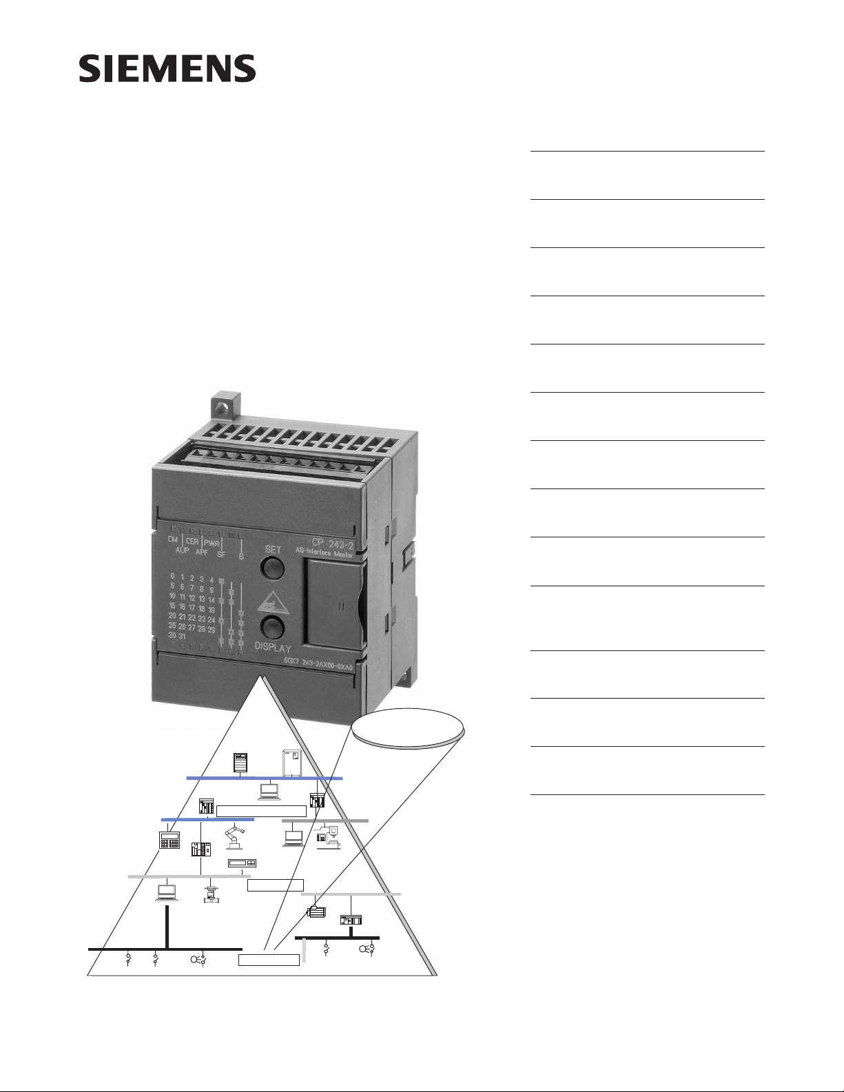
SIMATIC NET
CP 243-2
AS-Interface Master
Manual
Technical Description and
Installation Instructions
Interface to the User Program
in the S7-200 CPU
Access to the Data of the AS-i
Slaves
Signaling Errors and Diagnostics in the User Program
Command Interface
Eliminating Problems /
Error Displays
Appendix
AS-Interface Protocol Implementation Conformance Statements
1
2
3
4
5
6
A
07/2000
C79000-G8976-C142
Release 02
Industrial Ethernet
PROFIBUS
AS-Interface
AS-Interface
References
Note on the CE Mark
Support and Training
Glossary, Index
B
C
D
Page 2

Safety Guidelines
This manual contains notices which you should observe to ensure your own personal safety, as well as to
protect the product and connected equipment. These notices are highlighted in the manual by a warning
triangle and are marked as follows according to the level of danger:
Danger
!
indicates that death, severe personal injury or substantial property damage will result if proper precautions
are not taken.
Warning
!
indicates that death, severe personal injury or substantial property damage can result if proper precautions are not taken.
Caution
!
indicates that minor personal injury or property damage can result if proper precautions are not taken.
Note
draws your attention to particularly important information on the product, handling the
product, or to a particular part of the documentation.
Qualified Personnel
Only qualified personnel should be allowed to install and work on this equipment. Qualified persons are
defined as persons who are authorized to commission, to ground, and to tag circuits, equipment, and systems in accordance with established safety practices and standards.
Correct Usage
Note the following
Warning
!
Trademarks
The reproduction, transmission or use of this document or its
contents is not permitted without express written authority.
Offenders will be liable for damages. All rights, including rights
created by patent grant or registration of a utility model or design, are
reserved.
Siemens AG
A&D
Industrial Automation Systems
Postfach 4848,D-90327 Nürnberg
This device and its components may only be used for the applications described in the catalog or the
technical description, and only in connection with devices or components from other manufacturers which
have been approved or recommended by Siemens.
This product can only function correctly and safely if it is transported, stored, set up, and installed
correctly, and operated and maintained as recommended.
SIMATICR, SIMATIC HMIR and SIMATIC NETR are registered trademarks of the SIEMENS AG.
Third parties using for their own purpose any other names in this document which refer to trademarks
might infringe upon the rights of the trademark owners.
Disclaimer of LiabilityCopyright E Siemens AG 1999 All rights reserved
We have checked the contents of this manual for agreement with the
hardware and software described. Since deviations cannot be
precluded entirely, we cannot guarantee full agreement. However,
the data in this manual are reviewed regularly and any necessary
corrections included in subsequent editions. Suggestions for
improvement are welcomed.
Technical data subject to change.
E Siemens AG 1999
Siemens Aktiengesellschaft C79000-G8976-C142
Page 3

Preface
Purpose of the Manual
This manual supports you when using the CP 243-2 module. It explains how to
access AS-Interface actuators and AS-Interface sensors from an S7-22x CPU via
this module.
We recommend the following procedure when...
...You want an overall picture of the AS-Interface.
– First read the ‘AS-Interface Introduction and Basic Information’ manual (not
part of this documentation package). This contains general information
about the AS-Interface, abbreviated to AS-i in the following chapters.
...You want to set up an AS-i system and include the CP 243-2 module in it:
– You will find the relevant information about connecting and operating the
CP 243-2 in Chapter 3.
Requirements
To understand this document, you should be familiar with the manual ‘AS-Interface
Introduction and Basic Information’ (part of this documentation package).
Diskette with Sample Programs
The diskette supplied with this manual (S7-200 PROGR) contains sample
programs that will help you when programming the CP 243-2. These sample
programs were written with STEP 7-Micro/WIN32 and can be run on an S7-22x
CPU.
SIMA TIC NET CP 243-2 AS-i Master
C79000-G8976-C142/02
i
Page 4

Preface
ii
SIMA TIC NET CP 243-2 AS-i Master
C79000-G8976-C142/02
Page 5

Contents
1 Technical Description and Installation Instructions 1-1. . . . . . . . . . . . . . . . . . . . . . .
1.1 General Notes on Operation – Safety Warnings 1-2. . . . . . . . . . . . . . . . . . . . .
1.2 Uses of the Module 1-3. . . . . . . . . . . . . . . . . . . . . . . . . . . . . . . . . . . . . . . . . . . . . .
1.3 Technical Specifications of the Module 1-5. . . . . . . . . . . . . . . . . . . . . . . . . . . . .
1.4 Installing the Module 1-6. . . . . . . . . . . . . . . . . . . . . . . . . . . . . . . . . . . . . . . . . . . . .
1.5 Front Panel – Access to all Functions 1-7. . . . . . . . . . . . . . . . . . . . . . . . . . . . . .
1.6 Terminal Block 1-8. . . . . . . . . . . . . . . . . . . . . . . . . . . . . . . . . . . . . . . . . . . . . . . . . .
1.7 Modes of the CP 243-2 1-10. . . . . . . . . . . . . . . . . . . . . . . . . . . . . . . . . . . . . . . . . .
1.8 Displays and Operator Controls 1-11. . . . . . . . . . . . . . . . . . . . . . . . . . . . . . . . . . .
1.8.1 Status Display 1-12. . . . . . . . . . . . . . . . . . . . . . . . . . . . . . . . . . . . . . . . . . . . . . . . . .
1.8.2 Slave Display 1-14. . . . . . . . . . . . . . . . . . . . . . . . . . . . . . . . . . . . . . . . . . . . . . . . . . .
1.9 Configuring the AS-Interface with the SET Button 1-16. . . . . . . . . . . . . . . . . . . .
2 Interface to the User Program in the S7-200 CPU 2-1. . . . . . . . . . . . . . . . . . . . . . . . . .
2.1 Overview 2-2. . . . . . . . . . . . . . . . . . . . . . . . . . . . . . . . . . . . . . . . . . . . . . . . . . . . . . .
2.2 Addressing the CP 243-2 in the S7-200 CPU 2-4. . . . . . . . . . . . . . . . . . . . . . .
2.3 Meaning of the Data in the Digital Module 2-7. . . . . . . . . . . . . . . . . . . . . . . . . . .
2.3.1 Identification Register in the Digital Module 2-8. . . . . . . . . . . . . . . . . . . . . . . . .
2.3.2 Error Register in the Digital Module 2-9. . . . . . . . . . . . . . . . . . . . . . . . . . . . . . . .
2.3.3 Status Byte (Input Register 8DI) 2-10. . . . . . . . . . . . . . . . . . . . . . . . . . . . . . . . . . .
2.3.4 Control Byte (Output Register 8DO) 2-11. . . . . . . . . . . . . . . . . . . . . . . . . . . . . . .
2.4 Meaning of the Data in the Analog Module 2-12. . . . . . . . . . . . . . . . . . . . . . . . . .
2.4.1 Identification Register in the Analog Module 2-13. . . . . . . . . . . . . . . . . . . . . . . . .
2.4.2 Error Register in the Analog Module 2-14. . . . . . . . . . . . . . . . . . . . . . . . . . . . . . .
2.5 Access to the Analog Input and Output Words 2-16. . . . . . . . . . . . . . . . . . . . . . .
2.5.1 Analog Input Area 2-18. . . . . . . . . . . . . . . . . . . . . . . . . . . . . . . . . . . . . . . . . . . . . . .
2.5.2 Analog Output Area 2-21. . . . . . . . . . . . . . . . . . . . . . . . . . . . . . . . . . . . . . . . . . . . .
3 Access to the Data of the AS-i Slaves 3-1. . . . . . . . . . . . . . . . . . . . . . . . . . . . . . . . . . . .
3.1 Access to the Binary Data of the AS-i Slaves 3-2. . . . . . . . . . . . . . . . . . . . . . . .
3.1.1 Addressing the AS-i Slaves in the User Program 3-2. . . . . . . . . . . . . . . . . . . .
3.1.2 Access to the AS-i User Data 3-7. . . . . . . . . . . . . . . . . . . . . . . . . . . . . . . . . . . . .
3.2 Access to the Analog Data of the AS-i Slaves
(Slaves complying with Profile 7.3 or 7.4) 3-8. . . . . . . . . . . . . . . . . . . . . . . . . . .
3.2.1 Addressing the Analog AS-i Slaves in the User Program 3-8. . . . . . . . . . . . . .
3.2.2 Access to the AS-i Analog Data 3-15. . . . . . . . . . . . . . . . . . . . . . . . . . . . . . . . . . .
SIMA TIC NET CP 243-2 AS-i Master
C79000-G8976-C142/02
iii
Page 6

Contents
4 Signaling Errors and Diagnostics in the User Program 4-1. . . . . . . . . . . . . . . . . . . .
4.1 Signaling 4-2. . . . . . . . . . . . . . . . . . . . . . . . . . . . . . . . . . . . . . . . . . . . . . . . . . . . . . .
4.2 Example: Reading the Delta List 4-3. . . . . . . . . . . . . . . . . . . . . . . . . . . . . . . . . . .
5 Command Interface 5-1. . . . . . . . . . . . . . . . . . . . . . . . . . . . . . . . . . . . . . . . . . . . . . . . . . . . .
5.1 Command interface of the CP 243-2 5-2. . . . . . . . . . . . . . . . . . . . . . . . . . . . . . .
5.2 Description of the AS-i Commands 5-7. . . . . . . . . . . . . . . . . . . . . . . . . . . . . . . .
5.2.1 Set_Permanent_Parameter 5-13. . . . . . . . . . . . . . . . . . . . . . . . . . . . . . . . . . . . . . .
5.2.2 Get_Permanent_Parameter 5-14. . . . . . . . . . . . . . . . . . . . . . . . . . . . . . . . . . . . . . .
5.2.3 Write_Parameter 5-15. . . . . . . . . . . . . . . . . . . . . . . . . . . . . . . . . . . . . . . . . . . . . . . .
5.2.4 Read_Parameter 5-16. . . . . . . . . . . . . . . . . . . . . . . . . . . . . . . . . . . . . . . . . . . . . . . .
5.2.5 Store_Actual_Parameters 5-17. . . . . . . . . . . . . . . . . . . . . . . . . . . . . . . . . . . . . . . .
5.2.6 Set_Extended_Permanent_Configuration 5-18. . . . . . . . . . . . . . . . . . . . . . . . . . .
5.2.7 Get_Extended_Permanent_Configuration 5-19. . . . . . . . . . . . . . . . . . . . . . . . . . .
5.2.8 Store_Actual_Configuration 5-20. . . . . . . . . . . . . . . . . . . . . . . . . . . . . . . . . . . . . . .
5.2.9 Get_Extended_Actual_Configuration 5-21. . . . . . . . . . . . . . . . . . . . . . . . . . . . . . .
5.2.10 Set_LPS 5-22. . . . . . . . . . . . . . . . . . . . . . . . . . . . . . . . . . . . . . . . . . . . . . . . . . . . . . .
5.2.11 Set_Offline_Mode 5-23. . . . . . . . . . . . . . . . . . . . . . . . . . . . . . . . . . . . . . . . . . . . . . .
5.2.12 Select_Autoprogramming 5-24. . . . . . . . . . . . . . . . . . . . . . . . . . . . . . . . . . . . . . . . .
5.2.13 Set_Operation_Mode 5-25. . . . . . . . . . . . . . . . . . . . . . . . . . . . . . . . . . . . . . . . . . . .
5.2.14 Change_AS-i_Slave_Address 5-26. . . . . . . . . . . . . . . . . . . . . . . . . . . . . . . . . . . . .
5.2.15 Get_AS-i_Slave_Status 5-27. . . . . . . . . . . . . . . . . . . . . . . . . . . . . . . . . . . . . . . . . .
5.2.16 Get_LPS, Get_LAS, Get_LDS, Get_Flags 5-29. . . . . . . . . . . . . . . . . . . . . . . . . .
5.2.17 Get_Extended_T otal_Configuration 5-32. . . . . . . . . . . . . . . . . . . . . . . . . . . . . . . .
5.2.18 Store_Extended_T otal_Configuration 5-37. . . . . . . . . . . . . . . . . . . . . . . . . . . . . . .
5.2.19 Write_Extended_Parameter_List 5-43. . . . . . . . . . . . . . . . . . . . . . . . . . . . . . . . . .
5.2.20 Read_Extended_Parameter_Echo_List 5-45. . . . . . . . . . . . . . . . . . . . . . . . . . . . .
5.2.21 Read_Version_ID 5-47. . . . . . . . . . . . . . . . . . . . . . . . . . . . . . . . . . . . . . . . . . . . . . .
5.2.22 Read_AS-i_Slave_ID 5-48. . . . . . . . . . . . . . . . . . . . . . . . . . . . . . . . . . . . . . . . . . . .
5.2.23 Read_AS-i_Slave_ID1 5-49. . . . . . . . . . . . . . . . . . . . . . . . . . . . . . . . . . . . . . . . . . .
5.2.24 Write_AS-i_Slave_Extended_ID1 5-50. . . . . . . . . . . . . . . . . . . . . . . . . . . . . . . . . .
5.2.25 Read_AS-i_Slave_ID2 5-51. . . . . . . . . . . . . . . . . . . . . . . . . . . . . . . . . . . . . . . . . . .
5.2.26 Read_AS-i_Slave_I/O 5-52. . . . . . . . . . . . . . . . . . . . . . . . . . . . . . . . . . . . . . . . . . . .
5.2.27 Get_LPF 5-53. . . . . . . . . . . . . . . . . . . . . . . . . . . . . . . . . . . . . . . . . . . . . . . . . . . . . . .
5.2.28 Write_AS-i_Slave_Parameter_String 5-54. . . . . . . . . . . . . . . . . . . . . . . . . . . . . . .
5.2.29 Read_AS-i_Slave_Parameter_String 5-55. . . . . . . . . . . . . . . . . . . . . . . . . . . . . . .
5.2.30 Read_AS-i_Slave_ID_String 5-56. . . . . . . . . . . . . . . . . . . . . . . . . . . . . . . . . . . . . .
5.2.31 Read_AS-i_Slave_Diagnostic_String 5-57. . . . . . . . . . . . . . . . . . . . . . . . . . . . . . .
5.2.32 Read_Data_and_Delta_List 5-58. . . . . . . . . . . . . . . . . . . . . . . . . . . . . . . . . . . . . . .
6 Dealing with Problems / Error Displays 6-1. . . . . . . . . . . . . . . . . . . . . . . . . . . . . . . . . . .
6.1 Replacing a Defective AS-Interface Slave/Automatic Address Programming . . .
6-2
6.2 Error Displays of the CP 243-2 / Remedying Errors 6-3. . . . . . . . . . . . . . . . . .
iv
SIMA TIC NET CP 243-2 AS-i Master
C79000-G8976-C142/02
Page 7

Contents
A AS-Interface Protocol Implementation Conformance Statement (PICS) A-1. . . . .
B References B-1. . . . . . . . . . . . . . . . . . . . . . . . . . . . . . . . . . . . . . . . . . . . . . . . . . . . . . . . . . . . .
C Notes on the CE Mark C-1. . . . . . . . . . . . . . . . . . . . . . . . . . . . . . . . . . . . . . . . . . . . . . . . . . .
D SIMATIC NET – Support and Training D-1. . . . . . . . . . . . . . . . . . . . . . . . . . . . . . . . . . . .
Glossary
Index
SIMA TIC NET CP 243-2 AS-i Master
C79000-G8976-C142/02
v
Page 8

Contents
vi
SIMA TIC NET CP 243-2 AS-i Master
C79000-G8976-C142/02
Page 9

Technical Description and Installation Instructions
This chapter outlines the basic functions of the CP 243-2 and explains how the
module is installed and started up.
You will get to know the following properties of the CP 243-2:
The applications
The technical specifications
Display and control elements
Configuration
1
SIMA TIC NET CP 243-2 AS-i Master
C79000-G8976-C142/02
1-1
Page 10

Technical Description and Installation Instructions
1.1 General Notes on Operation – Safety Warnings
Caution
!
!
When handling and installing the CP 243-2, make sure that you keep to the ESD
guidelines.
The CP 243-2 must only be connected when the AS-i power supply unit is turned
off.
Caution
Noise immunity/grounding
To ensure the noise immunity of the CP 243-2, the CP 243-2 and the AS-i power
supply unit must be correctly grounded.
Caution
!
The AS-i power supply unit used must provide a low voltage, safely isolated from
the network. This safe isolation can be implemented according to the following
requirements:
VDE 0100 Part 410 = HD 384-4-4 = IEC 364-4-41
(as functional extra-low voltage with safe isolation) or
VDE 0805 = EN60950 = IEC 950
(as safety extra-low voltage SELV) or
VDE 0106 Part 101
1-2
SIMA TIC NET CP 243-2 AS-i Master
C79000-G8976-C142/02
Page 11

1.2 Uses of the Module
DP Slave and AS-i Master
The CP 243-2 module can be operated in the S7-200 programmable controller. It
allows the attachment of an S7-200 to the AS-Interface (as AS-i master). Both
interfaces can be used independent of each other.
Technical Description and Installation Instructions
AS-i power supply
Actuator/sensor
with slave ASIC
S7-22x CPU
Passive module
(without slave ASIC)
AS-i cable
CP 243-2
AS-i
master
Active module
(with slave ASIC)
AS-i branch
Figure 1-1 Example of a System Configuration with the CP 243-2
System Integration and Structure
The accompanying product information lists the CPUs with which the CP 243-2
can be operated.
From the point of view of the S7-22x CPU, the CP 243-2 represents two expansion
modules (an 8DI/8DO digital module and an 8AI/8AO analog module).
The design of the CP 243-2 corresponds to that of a standard expansion module
for an S7-200.
SIMA TIC NET CP 243-2 AS-i Master
C79000-G8976-C142/02
1-3
Page 12

Technical Description and Installation Instructions
Components Supplied
The CP 243-2 product includes the following components:
CP 243-2
Product information bulletin on the CP 243-2
1-4
SIMA TIC NET CP 243-2 AS-i Master
C79000-G8976-C142/02
Page 13

Technical Description and Installation Instructions
1.3 Technical Specifications of the Module
The technical specifications of the CP 243-2 module are as follows:
Table 1-1
Feature
AS-i cycle time 5 ms with 31 slaves
10 ms with 62 AS-i slaves using the extended
addressing mode
Configuration of the AS-Interface By a button on the front panel or using the total
configuration command (refer to the description of
the AS-i commands)
AS-i master profiles supported M1e
Attachment to the AS-i cable Via an S7-200 terminal block
Permitted current loading from terminal 1 to 3 or
from terminal 2 to 4 maximum 3 A
Address range One digital module with 8DI/8DO and one analog
module with 8AI/8AO
Power supply SIMA TIC backplane bus
Current consumption from 5 V DC
Power supply from the AS-i cable
Current consumption from the AS-i cable
Power consumption 3.7 W
Ambient conditions
5 V DC
max. 220 mA
According to the AS-i specification
max. 100 mA
Explanation/V alues
Operating temperature Horizontal installation: 0 to°C
Vertical installation: 0 to 45°C
Transport and storage temperature –40°C to +70°C
Relative humidity max. 95% at +25°C
Construction
Type of protection IP 20
Module format S7-200 expansion module
Dimensions (W x H x D) in mm 71 x 80 x 62
Weight approx. 250 g
SIMA TIC NET CP 243-2 AS-i Master
C79000-G8976-C142/02
1-5
Page 14

Technical Description and Installation Instructions
1.4 Installing the Module
Slots in the S7-200
The CP 243-2 can be inserted in all slots for expansion modules in the S7-200
programmable controller (CPUs 22x).
Possible Restrictions
There may, however, be restrictions depending on the CPU or power supply unit
being used in terms of the following:
Expandability with several expansion modules,
For further information, refer to /4/;
Electrical restrictions
The maximum current consumption from the S7 backplane bus must not be
exceeded. Please use the calculation table in /4/.
1-6
SIMA TIC NET CP 243-2 AS-i Master
C79000-G8976-C142/02
Page 15

Technical Description and Installation Instructions
1.5 Front Panel – Access to all Functions
Connection, Display and Control Elements
On the front panel, you have access to all the connection, display and control
elements of the CP 243-2.
During operation, the connection and control elements are protected by a front
cover.
Unused terminal block
B slave display
Status display
Group display
Slave display
Figure 1-2
SET
button
Display
button
AS-i cable connection
Connections, Operator Controls and Interpreting the Displays
For more detailed information, refer to the following sections.
SIMA TIC NET CP 243-2 AS-i Master
C79000-G8976-C142/02
1-7
Page 16

Technical Description and Installation Instructions
1.6 Terminal Block
Connections
The CP 243-2 has the following connections:
Two connections to the AS-i cable (bridged internally)
One connection for functional ground
The terminals are located under the cover of the front panel of the CP 243-2.
AS-i cables
Figure 1-3 Connecting the AS-i Cable
Connections to the AS-i Cable
The CP 243-2 has two connections for AS-i cables that are jumpered internally on
the CP 243-2.
This allows the CP 243-2 to be “looped” into the AS-i cable.
Caution
!
The load capacity of the AS-i contacts is a maximum of 3 A. If this value is exceed
on the AS-i cable, the CP 243-2 must not be “looped into” the AS-i cable but must
be connected by a separate cable (in this case only one pair of terminals of the
CP 243-2 is used). The CP 243-2 must be connected to the grounding conductor
via the ground terminal.
Functional ground
1-8
SIMA TIC NET CP 243-2 AS-i Master
C79000-G8976-C142/02
Page 17

Note
Technical Description and Installation Instructions
Functional ground
(terminal )
The CP 243-2 has a connection for functional ground. This connector should be
connected to the PE conductor with as little resistance as possible.
SIMA TIC NET CP 243-2 AS-i Master
C79000-G8976-C142/02
1-9
Page 18

Technical Description and Installation Instructions
1.7 Modes of the CP 243-2
Standard Operation
In this type of operation, the user program accesses the user data of the AS-i
slaves and the diagnostic data of the CP 243-2. Programming is simple and this
type of operation is adequate for the majority of automation tasks.
In standard operation, no commands or special parameters are transferred to the
slaves. This type of operation corresponds to the profile M0 of the AS-i master
specification.
Extended Operation
In extended operation, the user program uses the command interface of the
CP 243-2.
This means that the entire range of functions in the AS-i system is available to the
PLC programmer. In particular, the AS-i master calls (for example to assign
parameters to slaves) are available. This type of operation corresponds to the
profile M1e of the AS-i master specification.
1-10
SIMA TIC NET CP 243-2 AS-i Master
C79000-G8976-C142/02
Page 19

Technical Description and Installation Instructions
1.8 Displays and Operator Controls
Changing the Display Status – DISPLAY Button
You can change between the status display (basic status), slave display and
PROFIBUS display with the DISPLAY button. Each time you press the button, you
change to the next display status finally returning to the initial status.
In the slave display, the slaves on the AS-Interface are displayed in groups of 5
slaves. You can move on the display to the next group with the DISPLAY button.
First the standard or A slaves are displayed and then the B slaves (“B” LED is lit).
You return to the status display as follows:
After you have displayed the last group (slave 30B, 31B) by pressing the
DISPLAY button or
If you do not press the DISPLAY button for a longer period of time
(approximately 8 minutes).
Meaning of the LEDs
The front panel of the CP 243-2 has two rows of LEDs.
The LEDs CM, AUP, CER, APF, PWR and SF in the upper row represent the
status display.
The B LED indicates B slaves. It is lit when the slave display is active if B
slaves are displayed.
The first five LEDs of the lower row indicate the connected slaves (slave
display).
The other three LEDs indicate the slave group.
The meaning of the LEDs depends on the status of the group displays.
If all the LEDs of the group display are off, the status display is active; in other
words, the LEDs CM, AUP, CER, APF, PWR and SF indicate the status of the CP
243-2.
If at least one of the LEDs of the group display is lit, the status display goes off
(exception: “PWR” LED remains lit) and the slave display is active.
SET Button
The SET button is required to configure the CP 243-2.
SIMA TIC NET CP 243-2 AS-i Master
C79000-G8976-C142/02
1-11
Page 20

Technical Description and Installation Instructions
1.8.1 Status Display
Interpreting the Status Display
The status display is active when no group LEDs are lit.
The status display is the default display in the basic status of the CP 243-2.
Meaning of the LEDs
The LEDs have the following meaning:
Table 1-2
LED (color)
CM (yellow) Configuration
Status Meaning
This displays the operating mode of the CP 243-2.
Mode
LED lit: Configuration mode
LED unlit: Protected mode
The configuration mode is only required when putting the CP 243-2
into operation. In the configuration mode, the CP 243-2 activates all
connected AS-i slaves and exchanges data with them. For more
information about the configuration mode, refer to Section 1.9.
AUP (green) Autoprog
available
CER (yellow) Configuration
Error
In the protected mode of the CP 243-2, this indicates that automatic
address programming of an AS-i slave is possible. The automatic
address programming makes it much easier to exchange a defective
AS-i slave on the AS-i cable (for more detailed information refer to
Section 6.1).
This LED indicates whether the slave configuration detected on the
AS-i cable matches the expected configuration (LPS). If they do not
match, the CER LED is lit.
The CER LED is lit in the following situations:
When a configured AS-i slave does not exist on the AS-i cable (for
example failure of the slave).
When an AS-i slave exists on the AS-i cable but it was not
previously configured.
When a connected AS-i slave has different configuration data (I/O
configuration, ID code, extended ID1 code, extended ID2 code)
from the AS-i slave configured on the CP 243-2.
When the CP 243-2 is in the offline phase.
APF (red) AS-i Power Fail This indicates that the voltage supplied by the AS-i power supply unit
on the AS-i cable is too low or has failed.
PWR (green) Power The PWR LED (power) indicates that the CP 243-2 is supplied with
power.
1-12
SIMA TIC NET CP 243-2 AS-i Master
C79000-G8976-C142/02
Page 21

Technical Description and Installation Instructions
Table 1-2 , continued
LED (color) MeaningStatus
SF (red) System error This LED is lit in the following situations:
The CP 243-2 has detected an internal problem (for example a
defective EEPROM).
The CP 243-2 is unable to make the currently required mode
change (for example an AS-i slave with address 0 exists) when a
button is pressed.
SIMA TIC NET CP 243-2 AS-i Master
C79000-G8976-C142/02
1-13
Page 22

Technical Description and Installation Instructions
1.8.2 Slave Display
Interpreting the Slave Display Status
You can switch over to the slave display mode used by pressing the DISPLAY
button. You switch from group to group by pressing the DISPLAY button again: The
slave display is active when at least one group LED is lit.
Characteristics of the Slave Display
If the CP 243-2 is in the configuration mode, all detected AS-i slaves are
displayed.
If the CP 243-2 is in the protected mode, all active AS-i slaves are displayed.
In the protected mode, failed or existing but unconfigured AS-i slaves are
indicated by the corresponding LED flashing.
Display Statuses in Detail
The AS-i slaves are displayed in groups of five. The three group LEDs indicate
which group of 5 is being displayed in binary code. The 5 LEDs of the slave display
then indicate the detected or active AS-i slaves within the group.
To find out which slaves are active, select the group of 5 (line) corresponding to the
lit group LEDs. The currently lit LEDs of the slave display then indicate which
slaves within this group are currently active.
If a group of B slaves is displayed, the “B” LED is also lit.
1-14
SIMA TIC NET CP 243-2 AS-i Master
C79000-G8976-C142/02
Page 23

Example of a Slave Display
From the display shown below, you can obtain the following information:
The 2nd group LED is lit, i.e. the 2nd line from the top (corresponds to 21 =
2
; 2. group of 5; slaves 5–9).
DEC
If the 2nd and 4th LEDs are also lit within the slave display, this means that
slaves 6 and 8 are active.
If the “B” LED is also lit, then in this example, this would mean that slaves 6B
and 8B are active.
Technical Description and Installation Instructions
The intersecting
points mark slave 6
and slave 8.
LED/column 2 + 4
Figure 1-4 Example of a Slave Display
2nd
group
SIMA TIC NET CP 243-2 AS-i Master
C79000-G8976-C142/02
1-15
Page 24

Technical Description and Installation Instructions
1.9 Configuring the AS-Interface with the SET Button
Interpreting the Display Status
The CP 243-2 distinguishes between two operating modes on the AS-Interface:
Configuration mode
Protected mode
Pressing the SET button changes the operating mode.
Note
The SET button is only effective when the bit PLC_RUN = 0 is set in the control
byte of the CP 243-2. This is always the case when the S7-22x CPU is in the
STOP mode.
Configuration Mode
The configuration mode is used to install and start up an AS-i installation.
If the CP 243-2 is in the configuration mode (CM LED lit), it can exchange data
with every AS-i slave connected to the AS-i cable (except for an AS-i slave with
address ’0’). Newly added AS-i slaves are detected immediately by the master,
activated, and included in cyclic data exchange.
When installation and startup is completed, the CP 243-2 can be switched to the
protected mode using the SET button. At the same time, active AS-i slaves are
configured. The following data are then stored permanently on the CP 243-2:
The addresses of the AS-i slaves
The ID codes (ID code, extended ID1 code, extended ID2 code)
The I/O configuration
The current slave parameters
Protected Mode
In the protected mode, the CP 243-2 exchanges data only with the configured AS-i
slaves. In this sense, “configured” means that the slave addresses and the
configuration data stored on the CP 243-2 match the values of existing AS-i slaves.
1-16
SIMA TIC NET CP 243-2 AS-i Master
C79000-G8976-C142/02
Page 25

Note
Changing from the configuration mode to the protected mode is only possible
when there is no slave with address “0” connected to the AS-Interface. If a slave
“0” is connected, the “SF” LED lights up when the SET button is pressed.
Preparing to Configure
Make sure that the following situation applies:
The S7-22x CPU must be set to STOP (PLC_RUN=0).
The CP 243-2 and all AS-i slaves must be connected to the AS-Interface and
supplied with power by the AS-i power supply.
Configuring
Technical Description and Installation Instructions
1. Press the DISPLAY button to set the CP 243-2 display to the “status display”
mode (initial status).
2. Check whether the CP 243-2 is in the “configuration mode”. (”CM” LED lit ). If
not, change the CP 243-2 to the configuration mode using the SET button.
3. By changing to the slave display with the DISPLAY button, you can check
whether all the slaves connected to the AS-Interface exist.
4. Press the SET button. The CP 243-2 is configured.
At the same time, the CP 243-2 is changed to the protected mode; the “CM”
LED goes off.
The “CER” LED also goes off since following configuration, the “expected
configuration” stored on the CP 243-2 matches the “actual configuration” on the
AS-Interface.
Note
Configuring the CP 243-2 during an AS-Interface Power Fail (for example when
the AS-i power supply unit is turned off or when the CP 243-2 is not connected to
the AS-Interface) resets the configuration of the CP 243-2. This has the following
results:
No AS-i slaves are configured;
All AS-i slave parameters are set;
Automatic address programming is activated
SIMA TIC NET CP 243-2 AS-i Master
C79000-G8976-C142/02
(bit AUTO_ADDRESS_ENABLE = 1).
1-17
Page 26

Technical Description and Installation Instructions
1-18
SIMA TIC NET CP 243-2 AS-i Master
C79000-G8976-C142/02
Page 27

Interface to the User Program in the S7-200 CPU
This chapter explains how the CP 243-2 is addressed. You will learn the
significance of the data in the digital and in the analog module and you will learn
how to access the analog inputs and outputs.
2
SIMA TIC NET CP 243-2 AS-i Master
C79000-G8976-C142/02
2-1
Page 28

Interface to the User Program in the S7-200 CPU
2.1 Overview
CP 243-2 as Expansion Module in the S7-200
The CP 243-2 occupies 2 consecutive expansion module slots in the S7-200:
Digital module 8DI/8DO
Analog module 8AI/8AO
S7-200 CPU
User program
AS-i cable
Figure 2-1
CP 243-2
Digital module (8DI/8DO)
Status/error information
Control of the CP
Bank selection
Analog module (8AI/8AO)
Binary input/output data of the AS-i slaves
Analog input/output data of the
AS-i slaves
AS-i diagnostic information (delta list)
AS-i commands and response data
AS-i master
Digital Module
The digital module occupies 8 input and 8 output bits in the address area of the
digital inputs and outputs. The S7-200 CPU and the CP 243-2 are coordinated via
the digital module.
The data to be addressed in the analog module by the user program is selected
using bank select bits.
2-2
SIMA TIC NET CP 243-2 AS-i Master
C79000-G8976-C142/02
Page 29

Analog Module
The analog module occupies 16 input and 16 output bytes in the address area of
the analog inputs and outputs. Data exchange with the AS-i slaves is handled via
the analog module (see Figure 2-1).
The bank select mechanism means that a larger data area in total can be
addressed in the analog module than the addressable data area in the S7-200
CPU for the expansion module.
Interface to the User Program in the S7-200 CPU
SIMA TIC NET CP 243-2 AS-i Master
C79000-G8976-C142/02
2-3
Page 30

Interface to the User Program in the S7-200 CPU
2.2 Addressing the CP 243-2 in the S7-200 CPU
Address Areas
The start addresses of the address areas are determined by the following:
The type of S7-200 CPU being used
The slot of the CP 243-2 in the S7-200.
Examples
The following table contains examples of the addresses of the digital and analog
input/output areas with the possible configurations with a CPU 212 and CPU 214.
Example of a CPU 222 and a CP 243-2
CPU 222 CP 243-2
8DI 8 DO 8DI 8 DO 8AI 8AO
I0.0 Q0.0 I1.0 Q1.0 AIW0 AQW0
I0.1 Q0.1 I1.1 Q1.1 AIW2 AQW2
I0.2 Q0.2 I1.2 Q1.2 AIW4 AQW4
I0.3 Q0.3 I1.3 Q1.3 AIW6 AQW6
I0.4 Q0.4 I1.4 Q1.4 AIW8 AQW8
I0.5 Q0.5 I1.5 Q1.5 AIW10 AQW10
I0.6 Q0.6 I1.6 Q1.6 AIW12 AQW12
I0.7 Q0.7 I1.7 Q1.7 AIW14 AQW14
2-4
SIMA TIC NET CP 243-2 AS-i Master
C79000-G8976-C142/02
Page 31

Interface to the User Program in the S7-200 CPU
Example of a CPU 224 and a CP 243-2 Inserted Directly Beside the CPU
CPU 224 CP 243-2
14 DI 10 DO 8DI 8 DO 8AI 8AO
I0.0 Q0.0 I2.0 Q2.0 AIW0 AQW0
I0.1 Q0.1 I2.1 Q2.1 AIW2 AQW2
I0.2 Q0.2 I2.2 Q2.2 AIW4 AQW4
I0.3 Q0.3 I2.3 Q2.3 AIW6 AQW6
I0.4 Q0.4 I2.4 Q2.4 AIW8 AQW8
I0.5 Q0.5 I2.5 Q2.5 AIW10 AQW10
I0.6 Q0.6 I2.6 Q2.6 AIW12 AQW12
I0.7 Q0.7 I2.7 Q2.7 AIW14 AQW14
I1.0 Q1.0
I1.1 Q1.1
I1.2
I1.3
I1.4
I1.5
Example of a CPU 224, a CP 243-2 and a CP 243-2
CPU 224 CP 243-2 CP 243-2
14 DI 10 DO 8DI 8 DO 8AI 8AO 8DI 8 DO 8AI 8AO
I0.0 Q0.0 I2.0 Q2.0 AIW0 AQW0 I3.0 Q3.0 AIW16 AQW16
I0.1 Q0.1 I2.1 Q2.1 AIW2 AQW2 I3.1 Q3.1 AIW18 AQW18
I0.2 Q0.2 I2.2 Q2.2 AIW4 AQW4 I3.2 Q3.2 AIW20 AQW20
I0.3 Q0.3 I2.3 Q2.3 AIW6 AQW6 I3.3 Q3.3 AIW22 AQW22
I0.4 Q0.4 I2.4 Q2.4 AIW8 AQW8 I3.4 Q3.4 AIW24 AQW24
I0.5 Q0.5 I2.5 Q2.5 AIW10 AQW10 I3.5 Q3.5 AIW26 AQW26
I0.6 Q0.6 I2.6 Q2.6 AIW12 AQW12 I3.6 Q3.6 AIW28 AQW28
I0.7 Q0.7 I2.7 Q2.7 AIW14 AQW14 I3.7 Q3.7 AIW30 AQW30
I1.0 Q1.0
I1.1 Q1.1
I1.2
I1.3
I1.4
I1.5
SIMA TIC NET CP 243-2 AS-i Master
C79000-G8976-C142/02
2-5
Page 32

Interface to the User Program in the S7-200 CPU
Example of a CPU 224, an 8DI Module, a 3AI/1AO Module and a CP 243-2
CPU 224 Module Module CP 243-2
14DI 10 DO 8DI 3AI 1AO 8DI 8 DO 8AI 8AO
I0.0 Q0.0 I2.0 AIW0 AQW0 I3.0 Q2.0 AIW8 AQW4
I0.1 Q0.1 I2.1 AIW2 I3.1 Q2.1 AIW10 AQW6
I0.2 Q0.2 I2.2 AIW4 I3.2 Q2.2 AIW12 AQW8
I0.3 Q0.3 I2.3 I3.3 Q2.3 AIW14 AQW10
I0.4 Q0.4 I2.4 I3.4 Q2.4 AIW16 AQW12
I0.5 Q0.5 I2.5 I3.5 Q2.5 AIW18 AQW14
I0.6 Q0.6 I2.6 I3.6 Q2.6 AIW20 AQW16
I0.7 Q0.7 I2.7 I3.7 Q2.7 AIW22 AQW18
I1.0 Q1.0
I1.1 Q1.1
I1.2
I1.3
I1.4
I1.5
2-6
SIMA TIC NET CP 243-2 AS-i Master
C79000-G8976-C142/02
Page 33

Interface to the User Program in the S7-200 CPU
2.3 Meaning of the Data in the Digital Module
Overview
The digital module of the CP 243-2 consists of four registers:
Identification register, 8 bits (I/O module identifier)
Error register, 8 bits
Input register 8DI (status byte of the CP 243-2)
Output register 8DO (control byte of the CP 243-2)
Essentially, the functions shown in the following diagram are handled via these
registers:
S7-200 CPU
User program
AS-i cable
Figure 2-2
CP 243-2
Digital module (8DI/8DO)
Status/error information
Control of the CP
Bank selection
Analog module (8AI/8AO)
AS-i master
SIMA TIC NET CP 243-2 AS-i Master
C79000-G8976-C142/02
2-7
Page 34

Interface to the User Program in the S7-200 CPU
2.3.1 Identification Register in the Digital Module
Meaning
The identification register signals the I/O module identifier to indicate the existence
of an 8DI/8DO digital module with the value specified below.
The address at which the program can access the identification register depends
on the slot in which the CP 243-2 is inserted.
For further information about the special bit memory and its structure for I/O
modules, refer to /4/.
Range of Values
The identification register can be read via the special bit memory of the S7-200
CPU. It provides the fixed value 05H.
Example
Assuming that the CP 243-2 is inserted directly beside the S7-200 CPU.
The content of the identification register can be read from SMB8.
2-8
SIMA TIC NET CP 243-2 AS-i Master
C79000-G8976-C142/02
Page 35

Interface to the User Program in the S7-200 CPU
2.3.2 Error Register in the Digital Module
Meaning for the User Program
This register always supplies the value ”0”. The CP 243–2 reports errors using the
error register in the analog module (see Section 2.4.2).
Example of Access to the Error Register
If the CP 243–2 is inserted directly beside the S7–200 CPU, SMB9 constantly
supplies the value ”0”.
SIMA TIC NET CP 243-2 AS-i Master
C79000-G8976-C142/02
2-9
Page 36

Interface to the User Program in the S7-200 CPU
2.3.3 Status Byte (Input Register 8DI)
Meaning for the User Program
This register shows the status of the CP 243-2 relative to the AS-i master
interface.
Structure of the Status Byte
Bit 7 Bit 6 Bit 5 Bit 4 Bit 3 Bit 2 Bit 1 Bit 0
0 ASI_RESP 0 0 0 0 CP_READY ASI_MODE
Description of the Bits
Table 2-1
Bit
ASI_MODE 0 The CP 243-2 is in the protected mode.
CP_READY 0 The CP 243-2 is not yet operational after turning on
ASI_RESP 0/1 Response bit for the AS-i command interface (see
Value Meaning
1 The CP 243-2 is in the configuration mode.
the power supply. Evaluation of the I/O data or other
information from the CP is not permitted.
1 The CP 243-2 is operational.
Section 5.1).
2-10
SIMA TIC NET CP 243-2 AS-i Master
C79000-G8976-C142/02
Page 37

Interface to the User Program in the S7-200 CPU
2.3.4 Control Byte (Output Register 8DO)
Meaning for the User Program
The user program controls the data exchange with the CP 243-2 using this
register.
Structure of the Control Byte
Bit 7 Bit 6 Bit 5 Bit 4 Bit 3 Bit 2 Bit 1 Bit 0
PLC_RUN ASI_COM BS5 BS4 BS3 BS2 BS1 BS0
Description of the Bits
Table 2-2
Bit
BS0..BS5 0 ... 63
ASI_COM 0/1 Job bit for the AS-i command interface (see Section 5.1).
PLC_RUN In the STOP mode of the S7-200 CPU, the CP must send defined values to
Value Meaning
Bank select bits for changing the bank in the analog module
dec.
all AS-i slaves (see Chapter 3). Since the AS-i slave data are transferred
via the analog area and the S7-200 CPU does not set this area to ’0’ when
it changes from RUN to STOP, the CPU mode must be signaled to the
CP 243-2 using the PLC_RUN bit as follows:
0 Signal to the CP 243-2 that the S7-200 CPU is in the STOP
1 Signals to the CP 243-2 that the S7-200 CPU is in the RUN
(see Section 2.5).
mode.
The CP 243-2 sends ’0’ to all AS-i binary slaves. The analog
value transfer to analog output slaves is interrupted. The
S7-200 CPU sets the bit automatically to “0” at a change from
RUN to STOP.
mode.
The CP 243-2 sends the content of output bank 0 to all AS-i
slaves (see Section 2.4). The user program must set this bit to
“1” during startup (first scan).
Do not set the PLC_RUN bit permanently to “1” with the
S7-200 operating system functions such as “CPU
configuration/setting the outputs” or “force outputs”.
SIMA TIC NET CP 243-2 AS-i Master
C79000-G8976-C142/02
2-11
Page 38

Interface to the User Program in the S7-200 CPU
2.4 Meaning of the Data in the Analog Module
Overview
The analog module of the CP 243-2 consists of four areas:
Identification register, 8 bits (I/O module identifier)
Error register, 8 bits
8 analog input words (8 AI)
8 analog output words (8 AO)
The most important functions handled via these areas are shown in the diagram
below:
S7-200 CPU
User program
AS-i cable
Figure 2-3
CP 243-2
Digital module
(8DI/8DO)
Analog module (8AI/8AO)
Binary input/output data of the AS-i slaves
Analog input/output data of the
AS-i slaves
AS-i diagnostic information (delta list)
AS-i commands and response data
AS-i master
2-12
SIMA TIC NET CP 243-2 AS-i Master
C79000-G8976-C142/02
Page 39

Interface to the User Program in the S7-200 CPU
2.4.1 Identification Register in the Analog Module
Meaning
The identification register signals the I/O module identifier to indicate the existence
of an 8AI/8AO analog module with the value specified below.
The address at which the program can access the identification register depends
on the slot in which the CP 243-2 is inserted.
For further information about the special bit memory and its structure for I/O
modules refer to /4/.
Range of Values
The identification register can be read via the special bit memory area of the
S7-200 CPU. It provides the fixed value 1FH.
Example
Assuming that the CP 243-2 is inserted directly beside the S7-200 CPU.
The content of the identification register can be read via SMB 10.
SIMA TIC NET CP 243-2 AS-i Master
C79000-G8976-C142/02
2-13
Page 40

Interface to the User Program in the S7-200 CPU
2.4.2 Error Register in the Analog Module
Meaning for the User Program
With this register, the CP 243-2 signals errors to the user program.
Structure of the Error Register
Bit 7 Bit 6 Bit 5 Bit 4 Bit 3 Bit 2 Bit 1 Bit 0
0 0 0 0 0 APF 0 CER
Bit Description/Range of Values
Table 2-3
Bit
CER 0 AS-i configuration correct (only in the protected mode)
APF 0 AS-i voltage correct
Value Meaning
The “CER” LED is off
1 AS-i configuration error (only in the protected mode)
This indicates a difference between the slave configuration
detected on the AS-i cable and the desired configuration
configured on the CP 243-2.
The “CER” LED is lit (see Section 1.8.1 Status Display of the
CP 243-2).
The “APF” LED is off.
1 AS-i Power Fail.
This indicates that the voltage supplied on the AS-i cable by the
AS-i power supply unit is too low or there is a complete power
outage.
The “APF” LED is lit (see Section 1.8.1 Status Display of the
CP 243-2).
Note
The “CER” bit indicates configuration errors only in the protected mode. In the
configuration mode, the “CER” bit is always “0”.
2-14
The “CER” LED, on the other hand, indicates configuration errors both in the
configuration mode and in the protected mode.
SIMA TIC NET CP 243-2 AS-i Master
C79000-G8976-C142/02
Page 41

Example of Access to the Error Register
Assuming that the CP 243-2 is inserted directly beside the S7-200 CPU.
Evaluate the special memory bits SM 11.0 to SM 11.2 in the SM area (for more
information about the special bit memory area of the S7-200 CPU, refer to /4/).
If an error has occurred, bit SM 11.0 and/or bit SM 11.2 is set.
Interface to the User Program in the S7-200 CPU
SIMA TIC NET CP 243-2 AS-i Master
C79000-G8976-C142/02
2-15
Page 42

Interface to the User Program in the S7-200 CPU
2.5 Access to the Analog Input and Output Words
Principle
Using a bank-select mechanism, the 8 analog input words and the 8 analog output
words can be switched to 64 different analog input areas (banks) and 64 different
analog output areas (banks) on the CP 243-2.
Each of these banks is 8 words long.
Advantage
This bank-select mechanism has the advantage that the analog data area of 8
words available for the expansion module is increased according to the number of
banks.
Access in the User Program
The switchover to the various banks is made using bits BS0–BS5 in the control
byte of the CP 243-2 (see Section 2.3.4).
The bank select bits are binary coded and select banks as shown below:
BS5 BS4 BS3 BS2 BS1 BS0 Bank No.
0 0 0 0 0 0 Bank 0 selected
0 0 0 0 0 1 Bank 1 selected
0 0 0 0 1 0 Bank 2 selected
0 0 0 0 1 1 Bank 3 selected
0 0 0 1 0 0 Bank 4 selected
0 0 0 1 0 1 Bank 5 selected
0 0 0 1 1 0 Bank 6 selected
0 0 0 1 1 1 Bank 7 selected
0 0 1 0 0 0 Bank 8 selected
0 0 1 0 0 1 Bank 9 selected
0 0 1 0 1 0 Bank 10 selected
0 0 1 0 1 1 Bank 11 selected
0 0 1 1 0 0 Bank 12 selected
0 0 1 1 0 1 Bank 13 selected
0 0 1 1 1 0 Bank 14 selected
0 0 1 1 1 1 Bank 15 selected
0 1 0 0 0 0 Bank 16 selected
0 1 0 0 0 1 Bank 17 selected
0 1 0 0 1 0 Bank 18 selected
0 1 0 0 1 1 Bank 19 selected
0 1 0 1 0 0 Bank 20 selected
0 1 0 1 0 1 Bank 21 selected
0 1 0 1 1 0 Bank 22 selected
0 1 0 1 1 1 Bank 23 selected
0 1 1 0 0 0 Bank 24 selected
0 1 1 0 0 1 Bank 25 selected
2-16
SIMA TIC NET CP 243-2 AS-i Master
C79000-G8976-C142/02
Page 43

Interface to the User Program in the S7-200 CPU
BS5 Bank No.BS0BS1BS2BS3BS4
0 1 1 0 1 0 Bank 26 selected
0 1 1 0 1 1 Bank 27 selected
0 1 1 1 0 0 Bank 28 selected
0 1 1 1 0 1 Bank 29 selected
0 1 1 1 1 0 Bank 30 selected
0 1 1 1 1 1 Bank 31 selected
1 0 0 0 0 0 Bank 32 selected
1 0 0 0 0 1 Bank 33 selected
1 0 0 0 1 0 Bank 34 selected
1 0 0 0 1 1 Bank 35 selected
1 0 0 1 0 0 Bank 36 selected
1 0 0 1 0 1 Bank 37 selected
1 0 0 1 1 0 Bank 38 selected
1 0 0 1 1 1 Bank 39 selected
1 0 1 0 0 0 Bank 40 selected
1 0 1 0 0 1 Bank 41 selected
1 0 1 0 1 0 Bank 42 selected
1 0 1 0 1 1 Bank 43 selected
1 0 1 1 0 0 Bank 44 selected
1 0 1 1 0 1 Bank 45 selected
1 0 1 1 1 0 Bank 46 selected
1 0 1 1 1 1 Bank 47 selected
1 1 0 0 0 0 Bank 48 selected
1 1 0 0 0 1 Bank 49 selected
1 1 0 0 1 0 Bank 50 selected
1 1 0 0 1 1 Bank 51 selected
1 1 0 1 0 0 Bank 52 selected
1 1 0 1 0 1 Bank 53 selected
1 1 0 1 1 0 Bank 54 selected
1 1 0 1 1 1 Bank 55 selected
1 1 1 0 0 0 Bank 56 selected
1 1 1 0 0 1 Bank 57 selected
1 1 1 0 1 0 Bank 58 selected
1 1 1 0 1 1 Bank 59 selected
1 1 1 1 0 0 Bank 60 selected
1 1 1 1 0 1 Bank 61 selected
1 1 1 1 1 0 Bank 62 selected
1 1 1 1 1 1 Bank 63 selected
Caution
!
Make sure that the value of the bank select bits is located not only in the process
output image but that it is also transferred to the CP 243-2 before you access the
corresponding bank (see example in Table 5-1).
SIMA TIC NET CP 243-2 AS-i Master
C79000-G8976-C142/02
2-17
Page 44

Interface to the User Program in the S7-200 CPU
2.5.1 Analog Input Area
Assignment of the Input Areas
The input area of the analog module of the CP 243-2 is mapped to the analog
inputs of the user program using bank selection as shown below:
S7-200 CPU CP 243-2
Analog inputs
8 AIW
e.g. AIW0..AIW14
*) The address area depends on
the slot of the CP 243-2 (see
Section 2.2)
*)
Bank select bits
BS5...BS0
Bank 0
Bank 1
Bank 2
⋅
⋅
⋅
⋅
⋅
Bank 15
Bank 16
⋅
⋅
Bank 30
Bank 31
Bank 32
⋅
⋅
Bank 47
Bank 48
⋅
⋅
Bank 63
Memory
assignment
Binary inputs
slave 1 to 31 or
slave 1A to 31A
AS-i diagnostics
(Delta list)
Response data
reserved
Binary inputs
slave 1B to 31B
Analog inputs
slave 1 to 31
reserved
Figure 2-4
The bank select bits are set in the control byte of the digital module by the user
program (see Section 2.3.4).
Bank 0: Binary input data of the AS-i slaves 1 to 31 or 1A to 31A
With this analog input words, you can access the binary inputs of the standard
slaves or A slaves (slaves with extended addressing mode).
The structure of the input data is described in Section 3.1.
SIMA TIC NET CP 243-2 AS-i Master
2-18
C79000-G8976-C142/02
Page 45

Interface to the User Program in the S7-200 CPU
Bank 1: Diagnostics on the AS-Interface
The delta list of the AS-i slaves is indicated in this bank.
The delta list contains deviations of the existing AS-i slaves from the configuration
on the CP 243-2.
A set bit can indicate the following:
Missing slaves
Extra slaves (not in the configuration)
Slaves with incorrect I0/ID coding
The delta list is updated both in the configuration and in the protected mode.
The bytes and bits of the delta list are ordered as shown in the table below.
(m: start address of the analog input area of the CP 243-2)
Byte \ Bit Bit 7 Bit 6 Bit 5 Bit 4 Bit 3 Bit 2 Bit 1 Bit 0
Byte m+0 Slave 7
Slave 7A
Byte m+1 Slave 15
Slave 15A
Byte m+2 Slave 23
Slave 23A
Byte m+3 Slave 31
Slave 31A
Byte m+4 Slave 7B Slave 6B Slave 5B Slave 4B Slave 3B Slave 2B Slave 1B Slave 0B
Byte m+5 Slave 15B Slave 14B Slave 13B Slave 12B Slave 11B Slave 10B Slave 9B Slave 8B
Byte m+6 Slave 23B Slave 22B Slave 21B Slave 20B Slave 19B Slave 18B Slave 17B Slave 16B
Byte m+7 Slave 31B Slave 30B Slave 29B Slave 28B Slave 27B Slave 26B Slave 25B Slave 24B
Slave 6
Slave 6A
Slave 14
Slave 14A
Slave 22
Slave 22A
Slave 30
Slave 30A
Slave 5
Slave 5A
Slave 13
Slave 13A
Slave 21
Slave 21A
Slave 29
Slave 29A
Slave 4
Slave 4A
Slave 12
Slave 12A
Slave 20
Slave 20A
Slave 28
Slave 28A
Slave 3
Slave 3A
Slave 11
Slave 11A
Slave 19
Slave 19A
Slave 27
Slave 27A
Slave 2
Slave 2A
Slave 10
Slave 10A
Slave 18
Slave 18A
Slave 26
Slave 26A
Slave 1
Slave 1A
Slave 9
Slave 9A
Slave 17
Slave 17A
Slave 25
Slave 25A
Slave 0
Slave 0A
Slave 8
Slave 8A
Slave 16
Slave 16A
Slave 24
Slave 24A
Banks 2–15: Response data on the AS-Interface
These banks contain the response data of the command calls. The data structures
used and the codings are described in Section 5.2. The number of banks used
depends on the particular command.
Banks 16–30: Reserved area
These areas are reserved for later expansions and cannot be used.
Bank 31: Binary input data of the AS-i slaves 1B – 31B
Via these analog input words, you have access to the binary inputs of the B slaves
(slaves with the extended addressing mode).
The structure of the input data is described in Section 3.1.
SIMA TIC NET CP 243-2 AS-i Master
C79000-G8976-C142/02
2-19
Page 46

Interface to the User Program in the S7-200 CPU
Banks 32–47: Analog input data of the AS-i slaves
Via these areas, you can access the analog input data of the AS-i slaves that
support the AS-i slave profile 7.3 or 7.4 (see Section 3.1.2).
Banks 48–63: Reserved area
These areas are reserved for later expansions and cannot be used.
2-20
SIMA TIC NET CP 243-2 AS-i Master
C79000-G8976-C142/02
Page 47

2.5.2 Analog Output Area
Assignment of the Output Areas
The output area of the analog module of the CP 243-2 is mapped to the analog
outputs of the user program using bank selection as shown below:
S7-200 CPU CP 243-2
Interface to the User Program in the S7-200 CPU
Analog outputs
8 AIW
e.g. AIW0..AIW14
*) The address area depends on
the slot of the CP 243-2 (see
Section 2.2)
*)
Bank select bits
BS5...BS0
Bank 0
Bank 1
Bank 2
⋅
⋅
⋅
⋅
⋅
Bank 15
Bank 16
⋅
⋅
Bank 30
Bank 31
Bank 32
⋅
⋅
Bank 47
Bank 48
⋅
⋅
Bank 63
Memory
assignment
Binary outputs
slave 1 to 31 or
slave 1A to 31A
reserved
Command data
reserved
Binary outputs
slave 1B to 31B
Analog outputs
slave 1 to 31
reserved
Figure 2-5
Bank 0: Binary output data of the AS-i slaves 1 to 31 or 1A to 31A
Via these analog output words, you can access the binary outputs of the standard
slaves or A slaves (slaves with the extended addressing mode).
The structure of the output data is described in Section 3.1.
Bank 1: reserved
This area is reserved for later expansions and cannot be used.
SIMA TIC NET CP 243-2 AS-i Master
C79000-G8976-C142/02
2-21
Page 48

Interface to the User Program in the S7-200 CPU
Banks 2–15: Command data on the AS-Interface
Via this area, you can store command calls on the CP 243-2. The data structures
and codes used are described in Section 5.2. The number of banks used depends
on the particular command.
Banks 16–30: Reserved area
These areas are reserved for later expansions and cannot be used.
Bank 31: Binary output data of the AS-i slaves 1B – 31B
Using these analog output words, you can access the binary outputs of the B
slaves (slaves with the extended addressing mode).
The structure of the output data is described in Section 3.1.2.
Banks 32–47: Analog output data of the AS-i slaves
Via these areas, you can access the analog binary outputs of AS-i slaves that
support the AS-i slave profile 7.3 or 7.4 (see Section 3.1.2).
Banks 48–63: Reserved area
These areas are reserved for later expansions and cannot be used.
2-22
SIMA TIC NET CP 243-2 AS-i Master
C79000-G8976-C142/02
Page 49

Access to the Data of the AS-i Slaves
This chapter explains the AS-i master interface of the CP 243-2. The first part
covers addressing the AS-i slaves and access to the binary data of the slaves.
In the second part, addressing and access to the analog data of the AS-i slaves is
explained.
3
SIMA TIC NET CP 243-2 AS-i Master
C79000-G8976-C142/02
3-1
Page 50

Access to the Data of the AS-i Slaves
3.1 Access to the Binary Data of the AS-i Slaves
3.1.1 Addressing the AS-i Slaves in the User Program
Requirements
Before you can access the I/O data of the AS-i slaves, the following requirements
must be met:
Deactivate the filtering of the analog inputs for the CP 243–2 in the system data
block of the S7–200 CPU.
Set the “PLC_RUN” bit (bit 7) in the digital control byte to ’1’ at the beginning of
the cyclic program.
Access to the I/O data of the slaves is then only allowed when the “CP_Ready”
bit (bit 1) in the digital status byte is set to ’1’.
Access to the Binary Values
The CP 243-2 assigns four bits (a nibble) in the input and output data area for
each AS-i slave. The PLC can write (slave output data) and read (slave input data)
this nibble.
This allows bi-directional slaves to be addressed.
3-2
SIMA TIC NET CP 243-2 AS-i Master
C79000-G8976-C142/02
Page 51

Access to the Data of the AS-i Slaves
Assignment of the AS-i Input Data of the Standard or A Slaves (Bank 0 in the
Analog Input Area of the CP)
Bank Byte no. Bit 7–4 Bit 3–0
0 m+0 reserved Slave 1 or slave 1A
Bit 3 | Bit 2 | Bit 1 | Bit 0
0 m+1 Slave 2 or slave 2A Slave 3 or slave 3A
0 m+2 Slave 4 or slave 4A Slave 5 or slave 5A
0 m+3 Slave 6 or slave 6A Slave 7 or slave 7A
0 m+4 Slave 8 or slave 8A Slave 9 or slave 9A
0 m+5 Slave 10 or slave 10A Slave 11 or slave 11A
0 m+6 Slave 12 or slave 12A Slave 13 or slave 13A
0 m+7 Slave 14 or slave 14A Slave 15 or slave 15A
0 m+8 Slave 16 or slave 16A Slave 17 or slave 17A
0 m+9 Slave 18 or slave 18A Slave 19 or slave 19A
0 m+10 Slave 20 or slave 20A Slave 21 or slave 21A
0 m+11 Slave 22 or slave 22A Slave 23 or slave 23A
0 m+12 Slave 24 or slave 24A Slave 25 or slave 25A
0 m+13 Slave 26 or slave 26A Slave 27 or slave 27A
0 m+14 Slave 28 or slave 28A Slave 29 or slave 29A
0 m+15 Slave 30 or slave 30A
Bit 3 | Bit 2 | Bit 1 | Bit 0
Slave 31 or slave 31A
Bit 3 | Bit 2 | Bit 1 | Bit 0
m = start address of the CP analog module in the input direction
Assignment of the AS-i Output Data of the Standard or A Slaves (Bank 0 in the
Analog Output Area of the CP)
Bank Byte no. Bit 7–4 Bit 3–0
0 n+0 reserved Slave 1 or slave 1A
Bit 3 | Bit 2 | Bit 1 | Bit 0
0 n+1 Slave 2 or slave 2A Slave 3 or slave 3A
0 n+2 Slave 4 or slave 4A Slave 5 or slave 5A
0 n+3 Slave 6 or slave 6A Slave 7 or slave 7A
0 n+4 Slave 8 or slave 8A Slave 9 or slave 9A
0 n+5 Slave 10 or slave 10A Slave 11 or slave 11A
0 n+6 Slave 12 or slave 12A Slave 13 or slave 13A
0 n+7 Slave 14 or slave 14A Slave 15 or slave 15A
0 n+8 Slave 16 or slave 16A Slave 17 or slave 17A
0 n+9 Slave 18 or slave 18A Slave 19 or slave 19A
0 n+10 Slave 20 or slave 20A Slave 21 or slave 21A
0 n+11 Slave 22 or slave 22A Slave 23 or slave 23A
0 n+12 Slave 24 or slave 24A Slave 25 or slave 25A
0 n+13 Slave 26 or slave 26A Slave 27 or slave 27A
0 n+14 Slave 28 or slave 28A Slave 29 or slave 29A
0 n+15 Slave 30 or slave 30A
Bit 3 | Bit 2 | Bit 1 | Bit 0
Slave 31 or slave 31A
Bit 3 | Bit 2 | Bit 1 | Bit 0
n = start address of the CP analog module in the output direction
SIMA TIC NET CP 243-2 AS-i Master
C79000-G8976-C142/02
3-3
Page 52

Access to the Data of the AS-i Slaves
Assignment of the AS-i Input Data of the B Slaves
(Bank 31 in the Analog Input Direction of the CP)
Bank Byte no. Bit 7–4 Bit 3–0
31 m+0 reserved Slave 1B
31 m+1 Slave 2B Slave 3B
31 m+2 Slave 4B Slave 5B
31 m+3 Slave 6B Slave 7B
31 m+4 Slave 8B Slave 9B
31 m+5 Slave 10B Slave 11B
31 m+6 Slave 12B Slave 13B
31 m+7 Slave 14B Slave 15B
31 m+8 Slave 16B Slave 17B
31 m+9 Slave 18B Slave 19B
31 m+10 Slave 20B Slave 21B
31 m+11 Slave 22B Slave 23B
31 m+12 Slave 24B Slave 25B
31 m+13 Slave 26B Slave 27B
31 m+14 Slave 28B Slave 29B
31 m+15 Slave 30B
Bit 3 | Bit 2 | Bit 1 | Bit 0
Bit 3 | Bit 2 | Bit 1 | Bit 0
Slave 31B
Bit 3 | Bit 2 | Bit 1 | Bit 0
m = start address of the CP analog module in the input direction
Assignment of the AS-i Output Data of the B Slaves
(Bank 31 in the Analog Output Area of the CP)
Bank Byte No. Bit 7–4 Bit 3–0
31 n+0 reserved Slave 1B
Bit 3 | Bit 2 | Bit 1 | Bit 0
31 n+1 Slave 2B Slave 3B
31 n+2 Slave 4B Slave 5B
31 n+3 Slave 6B Slave 7B
31 n+4 Slave 8B Slave 9B
31 n+5 Slave 10B Slave 11B
31 n+6 Slave 12B Slave 13B
31 n+7 Slave 14B Slave 15B
31 n+8 Slave 16B Slave 17B
31 n+9 Slave 18B Slave 19B
31 n+10 Slave 20B Slave 21B
31 n+11 Slave 22B Slave 23B
31 n+12 Slave 24B Slave 25B
31 n+13 Slave 26B Slave 27B
31 n+14 Slave 28B Slave 29B
31 n+15 Slave 30B
Bit 3 | Bit 2 | Bit 1 | Bit 0
Slave 31B
Bit 3 | Bit 2 | Bit 1 | Bit 0
3-4
n = start address of the CP analog module in the output direction
SIMA TIC NET CP 243-2 AS-i Master
C79000-G8976-C142/02
Page 53

Access to the Data of the AS-i Slaves
Data Exchange in the STOP Mode of the S7-22x CPU
In the STOP mode, the S7-22x CPU sets bit PLC_RUN in the digital control area
to “0” automatically. As a result, the CP 243-2 outputs “0” data to all binary slaves.
Special Feature of Analog Slaves
If you use analog slaves complying with profile 7.3 or 7.4 the following points
apply:
In the input direction, the CP 243-2 sets the nibbles assigned to the slaves to
“0”.
In the output direction, the CP 243-2 ignores the nibbles assigned to these
slaves.
Access to the analog data is described in Section 3.1.2.
SIMA TIC NET CP 243-2 AS-i Master
C79000-G8976-C142/02
3-5
Page 54

Access to the Data of the AS-i Slaves
Example
Figure 3-1 shows an example of the CP 243-2 addressing four AS-i slaves. In the
example, m = 0 is the start address for the input data and n = 0 is the start address
for the output data.
The bits relevant for the user program (existing AS-i slaves) are shown on a gray
background. The bits on a white background are irrelevant for the user program.
CP 243-2
16
input bytes
AS-i slaves
Figure 3-1
output bytes16
0
1
Bit 3
2
Bit 3
.
.
.
15
Bit 3
Bit 1
Bit 2
Bit 3
Slave 2 Slave 3
Bit 1
Slave 4
Bit 1
Bit 2
Slave 30
Bit 1
Bit 2
567
Slave no. 2 Slave no. 3 Slave no. 4
Slave 1
Bit 0
Bit 3
Bit 3
Bit 0
Slave 5
Bit 0
Bit 3
Slave 31
Bit 3
Bit 0
4 I module 4 I/4 O module2 I/2 O module 4 O module
4 I module
Bit 2Bit 2
Bit 2
Bit 2
Bit 0
Bit 1Bit 2
Bit 1
Bit 0
Bit 0
Bit 1
Bit 0
Bit 1
0
234
1
0
1
2
.
.
.
15
Bit 1
Bit 2
Bit 3
Slave 2 Slave 3
Bit 2
Bit 3 Bit 1 Bit 0
Slave 4
Bit 2
Bit 3
Bit 1
Slave 30 Slave 31
Bit 1
Bit 2
Bit 3
7
56
Slave 1
Bit 0 Bit 0
Bit 0
Bit 0
Slave no. 31
Bit 3
Bit 3
Bit 3
Bit 3
Bit 2
Bit 2
Slave 5
Bit 2
Bit 2
Bit 1
Bit 1
Bit 1
Bit 1
1234
Bit 0
Bit 0
Bit 0
0
In the figure above, for example, the 2I/2O module (AS-i slave number 3 with two
inputs and two outputs) occupies bits 0 and 1 in input byte 1 and bits 2 and 3 in
output byte 1.
The assignment of the AS-i terminals of the bus modules to the data bits of the
input/output bytes is shown below based on the example of slave number 3:
3-6
Input byte 1
Terminal 2 on the AS-i bus module
Terminal 1 on the AS-i bus module
Output byte 1
Terminal 4 on the AS-i bus module
Terminal 3 on the AS-i bus module
1 0 Bit no.
3 2 Bit no.
SIMA TIC NET CP 243-2 AS-i Master
C79000-G8976-C142/02
Page 55

3.1.2 Access to the AS-i User Data
Data Access with STEP 7 Micro
To access the binary data of the slaves, you use the analog transfer commands of
the STEP 7 Micro/WIN32 programming language.
Example
If you want to access individual bits of the slave data, you can use the method
shown in the following sample program.
The example created with STEP 7 Micro/WIN32 is valid for a CPU 222 with a
CP 243-2 plugged in directly beside it:
OB1 (STL)
NETWORK 1
LD SM0.1 //If: bit “First Scan”:
SI Q1.7, 1 //PLC_RUN = 1
LD I1.1 //If: CP 243-2_READY
CALL 1 //Then: AS-i I/O processing (standard or A slaves)
Access to the Data of the AS-i Slaves
SBR 1 (STL)
NETWORK 1
LD SM0.0 //Always 1
RI Q1.0,6 //Select bank 0
BMW AIW0, VW100, 8 //Transfer standard slaves
SI Q1.0,5 //Select bank 31
BMW AIW0, VW116, 8 //Transfer B slaves
//Below, several examples of access to AS-i bits
LD V100.0 //If bit 1 of slave 1
A V115.1 //And bit 2 of slave 31
A V116.0 //And bit 1 of slave 1B
= V203.2 //The bit 3 of slave 7 = 1
LD SM0.0 //Always 1
RI Q1.0,6 //Select bank 0
BMW VW900, AOW0, 8 //Transfer standard slaves
SI Q1.0,5 //Select bank 31
BMW AIW0, AOW0, 8 //Transfer B slaves
SIMA TIC NET CP 243-2 AS-i Master
C79000-G8976-C142/02
3-7
Page 56

Access to the Data of the AS-i Slaves
3.2 Access to the Analog Data of the AS-i Slaves (Slaves complying with Profile 7.3 or 7.4)
3.2.1 Addressing the Analog AS-i Slaves in the User Program
Requirements
Before you can access the I/O data of the AS-i slaves, the following requirements
must be met:
Deactivate the filtering of the analog inputs for the CP 243–2 in the system data
block of the S7–200 CPU.
Set the “PLC_RUN” bit (bit 7) in the digital control byte to ’1’ at the beginning of
the cyclic program.
Access to the I/O data of the slaves is then only allowed when the “CP_Ready”
bit (bit 1) in the digital status byte is set to ’1’.
The following explanations do not apply to analog slaves complying with profile 7.1
or 7.2. Analog value transfer for these slaves is not supported by the CP 243-2.
Access to the Analog Values
The CP 243-2 assigns four words in the input area and four words in the output
area for each AS-i slave. The PLC can write these values (analog outputs) or read
these values (analog inputs).
Assignment of the AS-i Analog Data
Bank Byte no. Meaning
32 0 Slave 1, channel 1, high byte
32 1 Slave 1, channel 1, low byte
32 2 Slave 1, channel 2, high byte
32 3 Slave 1, channel 2, low byte
32 4 Slave 1, channel 3, high byte
32 5 Slave 1, channel 3, low byte
32 6 Slave 1, channel 4, high byte
32 7 Slave 1, channel 4, low byte
32 8 Slave 2, channel 1, high byte
32 9 Slave 2, channel 1, low byte
32 10 Slave 2, channel 2, high byte
32 11 Slave 2, channel 2, low byte
32 12 Slave 2, channel 3, high byte
32 13 Slave 2, channel 3, low byte
32 14 Slave 2, channel 4, high byte
32 15 Slave 2, channel 4, low byte
3-8
SIMA TIC NET CP 243-2 AS-i Master
C79000-G8976-C142/02
Page 57

Bank MeaningByte no.
33 0 Slave 3, channel 1, high byte
33 1 Slave 3, channel 1, low byte
33 2 Slave 3, channel 2, high byte
33 3 Slave 3, channel 2, low byte
33 4 Slave 3, channel 3, high byte
33 5 Slave 3, channel 3, low byte
33 6 Slave 3, channel 4, high byte
33 7 Slave 3, channel 4, low byte
33 8 Slave 4, channel 1, high byte
33 9 Slave 4, channel 1, low byte
33 10 Slave 4, channel 2, high byte
33 11 Slave 4, channel 2, low byte
33 12 Slave 4, channel 3, high byte
33 13 Slave 4, channel 3, low byte
33 14 Slave 4, channel 4, high byte
33 15 Slave 4, channel 4, low byte
34 0 Slave 5, channel 1, high byte
34 1 Slave 5, channel 1, low byte
34 2 Slave 5, channel 2, high byte
34 3 Slave 5, channel 2, low byte
34 4 Slave 5, channel 3, high byte
34 5 Slave 5, channel 3, low byte
34 6 Slave 5, channel 4, high byte
34 7 Slave 5, channel 4, low byte
34 8 Slave 6, channel 1, high byte
34 9 Slave 6, channel 1, low byte
34 10 Slave 6, channel 2, high byte
34 11 Slave 6, channel 2, low byte
34 12 Slave 6, channel 3, high byte
34 13 Slave 6, channel 3, low byte
34 14 Slave 6, channel 4, high byte
34 15 Slave 6, channel 4, low byte
35 0 Slave 7, channel 1, high byte
35 1 Slave 7, channel 1, low byte
35 2 Slave 7, channel 2, high byte
35 3 Slave 7, channel 2, low byte
35 4 Slave 7, channel 3, high byte
35 5 Slave 7, channel 3, low byte
35 6 Slave 7, channel 4, high byte
35 7 Slave 7, channel 4, low byte
35 8 Slave 8, channel 1, high byte
35 9 Slave 8, channel 1, low byte
35 10 Slave 8, channel 2, high byte
35 11 Slave 8, channel 2, low byte
35 12 Slave 8, channel 3, high byte
35 13 Slave 8, channel 3, low byte
35 14 Slave 8, channel 4, high byte
35 15 Slave 8, channel 4, low byte
36 0 Slave 9, channel 1, high byte
Access to the Data of the AS-i Slaves
SIMA TIC NET CP 243-2 AS-i Master
C79000-G8976-C142/02
3-9
Page 58

Access to the Data of the AS-i Slaves
Bank MeaningByte no.
36 1 Slave 9, channel 1, low byte
36 2 Slave 9, channel 2, high byte
36 3 Slave 9, channel 2, low byte
36 4 Slave 9, channel 3, high byte
36 5 Slave 9, channel 3, low byte
36 6 Slave 9, channel 4, high byte
36 7 Slave 9, channel 4, low byte
36 8 Slave 10, channel 1, high byte
36 9 Slave 10, channel 1, low byte
36 10 Slave 10, channel 2, high byte
36 11 Slave 10, channel 2, low byte
36 12 Slave 10, channel 3, high byte
36 13 Slave 10, channel 3, low byte
36 14 Slave 10, channel 4, high byte
36 15 Slave 10, channel 4, low byte
37 0 Slave 11, channel 1, high byte
37 1 Slave 11, channel 1, low byte
37 2 Slave 11, channel 2, high byte
37 3 Slave 11, channel 2, low byte
37 4 Slave 11, channel 3, high byte
37 5 Slave 11, channel 3, low byte
37 6 Slave 11, channel 4, high byte
37 7 Slave 11, channel 4, low byte
37 8 Slave 12, channel 1, high byte
37 9 Slave 12, channel 1, low byte
37 10 Slave 12, channel 2, high byte
37 11 Slave 12, channel 2, low byte
37 12 Slave 12, channel 3, high byte
37 13 Slave 12, channel 3, low byte
37 14 Slave 12, channel 4, high byte
37 15 Slave 12, channel 4, low byte
38 0 Slave 13, channel 1, high byte
38 1 Slave 13, channel 1, low byte
38 2 Slave 13, channel 2, high byte
38 3 Slave 13, channel 2, low byte
38 4 Slave 13, channel 3, high byte
38 5 Slave 13, channel 3, low byte
38 6 Slave 13, channel 4, high byte
38 7 Slave 13, channel 4, low byte
38 8 Slave 14, channel 1, high byte
38 9 Slave 14, channel 1, low byte
38 10 Slave 14, channel 2, high byte
38 11 Slave 14, channel 2, low byte
38 12 Slave 14, channel 3, high byte
38 13 Slave 14, channel 3, low byte
38 14 Slave 14, channel 4, high byte
38 15 Slave 14, channel 4, low byte
39 0 Slave 15, channel 1, high byte
39 1 Slave 15, channel 1, low byte
3-10
SIMA TIC NET CP 243-2 AS-i Master
C79000-G8976-C142/02
Page 59

Bank MeaningByte no.
39 2 Slave 15, channel 2, high byte
39 3 Slave 15, channel 2, low byte
39 4 Slave 15, channel 3, high byte
39 5 Slave 15, channel 3, low byte
39 6 Slave 15, channel 4, high byte
39 7 Slave 15, channel 4, low byte
39 8 Slave 16, channel 1, high byte
39 9 Slave 16, channel 1, low byte
39 10 Slave 16, channel 2, high byte
39 11 Slave 16, channel 2, low byte
39 12 Slave 16, channel 3, high byte
39 13 Slave 16, channel 3, low byte
39 14 Slave 16, channel 4, high byte
39 15 Slave 16, channel 4, low byte
40 0 Slave 17, channel 1, high byte
40 1 Slave 17, channel 1, low byte
40 2 Slave 17, channel 2, high byte
40 3 Slave 17, channel 2, low byte
40 4 Slave 17, channel 3, high byte
40 5 Slave 17, channel 3, low byte
40 6 Slave 17, channel 4, high byte
40 7 Slave 17, channel 4, low byte
40 8 Slave 18, channel 1, high byte
40 9 Slave 18, channel 1, low byte
40 10 Slave 18, channel 2, high byte
40 11 Slave 18, channel 2, low byte
40 12 Slave 18, channel 3, high byte
40 13 Slave 18, channel 3, low byte
40 14 Slave 18, channel 4, high byte
40 15 Slave 18, channel 4, low byte
41 0 Slave 19, channel 1, high byte
41 1 Slave 19, channel 1, low byte
41 2 Slave 19, channel 2, high byte
41 3 Slave 19, channel 2, low byte
41 4 Slave 19, channel 3, high byte
41 5 Slave 19, channel 3, low byte
41 6 Slave 19, channel 4, high byte
41 7 Slave 19, channel 4, low byte
41 8 Slave 20, channel 1, high byte
41 9 Slave 20, channel 1, low byte
41 10 Slave 20, channel 2, high byte
41 11 Slave 20, channel 2, low byte
41 12 Slave 20, channel 3, high byte
41 13 Slave 20, channel 3, low byte
41 14 Slave 20, channel 4, high byte
41 15 Slave 20, channel 4, low byte
42 0 Slave 21, channel 1, high byte
42 1 Slave 21, channel 1, low byte
42 2 Slave 21, channel 2, high byte
Access to the Data of the AS-i Slaves
SIMA TIC NET CP 243-2 AS-i Master
C79000-G8976-C142/02
3-11
Page 60

Access to the Data of the AS-i Slaves
Bank MeaningByte no.
42 3 Slave 21, channel 2, low byte
42 4 Slave 21, channel 3, high byte
42 5 Slave 21, channel 3, low byte
42 6 Slave 21, channel 4, high byte
42 7 Slave 21, channel 4, low byte
42 8 Slave 22, channel 1, high byte
42 9 Slave 22, channel 1, low byte
42 10 Slave 22, channel 2, high byte
42 11 Slave 22, channel 2, low byte
42 12 Slave 22, channel 3, high byte
42 13 Slave 22, channel 3, low byte
42 14 Slave 22, channel 4, high byte
42 15 Slave 22, channel 4, low byte
43 0 Slave 23, channel 1, high byte
43 1 Slave 23, channel 1, low byte
43 2 Slave 23, channel 2, high byte
43 3 Slave 23, channel 2, low byte
43 4 Slave 23, channel 3, high byte
43 5 Slave 23, channel 3, low byte
43 6 Slave 23, channel 4, high byte
43 7 Slave 23, channel 4, low byte
43 8 Slave 24, channel 1, high byte
43 9 Slave 24, channel 1, low byte
43 10 Slave 24, channel 2, high byte
43 11 Slave 24, channel 2, low byte
43 12 Slave 24, channel 3, high byte
43 13 Slave 24, channel 3, low byte
43 14 Slave 24, channel 4, high byte
43 15 Slave 24, channel 4, low byte
44 0 Slave 25, channel 1, high byte
44 1 Slave 25, channel 1, low byte
44 2 Slave 25, channel 2, high byte
44 3 Slave 25, channel 2, low byte
44 4 Slave 25, channel 3, high byte
44 5 Slave 25, channel 3, low byte
44 6 Slave 25, channel 4, high byte
44 7 Slave 25, channel 4, low byte
44 8 Slave 26, channel 1, high byte
44 9 Slave 26, channel 1, low byte
44 10 Slave 26, channel 2, high byte
44 11 Slave 26, channel 2, low byte
44 12 Slave 26, channel 3, high byte
44 13 Slave 26, channel 3, low byte
44 14 Slave 26, channel 4, high byte
44 15 Slave 26, channel 4, low byte
45 0 Slave 27, channel 1, high byte
45 1 Slave 27, channel 1, low byte
45 2 Slave 27, channel 2, high byte
45 3 Slave 27, channel 2, low byte
3-12
SIMA TIC NET CP 243-2 AS-i Master
C79000-G8976-C142/02
Page 61

Bank MeaningByte no.
45 4 Slave 27, channel 3, high byte
45 5 Slave 27, channel 3, low byte
45 6 Slave 27, channel 4, high byte
45 7 Slave 27, channel 4, low byte
45 8 Slave 28, channel 1, high byte
45 9 Slave 28, channel 1, low byte
45 10 Slave 28, channel 2, high byte
45 11 Slave 28, channel 2, low byte
45 12 Slave 28, channel 3, high byte
45 13 Slave 28, channel 3, low byte
45 14 Slave 28, channel 4, high byte
45 15 Slave 28, channel 4, low byte
46 0 Slave 29, channel 1, high byte
46 1 Slave 29, channel 1, low byte
46 2 Slave 29, channel 2, high byte
46 3 Slave 29, channel 2, low byte
46 4 Slave 29, channel 3, high byte
46 5 Slave 29, channel 3, low byte
46 6 Slave 29, channel 4, high byte
46 7 Slave 29, channel 4, low byte
46 8 Slave 30, channel 1, high byte
46 9 Slave 30, channel 1, low byte
46 10 Slave 30, channel 2, high byte
46 11 Slave 30, channel 2, low byte
46 12 Slave 30, channel 3, high byte
46 13 Slave 30, channel 3, low byte
46 14 Slave 30, channel 4, high byte
46 15 Slave 30, channel 4, low byte
47 0 Slave 31, channel 1, high byte
47 1 Slave 31, channel 1, low byte
47 2 Slave 31, channel 2, high byte
47 3 Slave 31, channel 2, low byte
47 4 Slave 31, channel 3, high byte
47 5 Slave 31, channel 3, low byte
47 6 Slave 31, channel 4, high byte
47 7 Slave 31, channel 4, low byte
47 8 reserved
47 9 reserved
47 10 reserved
47 11 reserved
47 12 reserved
47 13 reserved
47 14 reserved
47 15 reserved
Access to the Data of the AS-i Slaves
Read access: Read analog input data from AS-i slaves
Write access: Write analog output data to AS-i slaves
SIMA TIC NET CP 243-2 AS-i Master
C79000-G8976-C142/02
3-13
Page 62

Access to the Data of the AS-i Slaves
Representation of the Analog Values
The analog values must be interpreted complying with slave profile 7.3 or 7.4 as
16-bit values in two’s complement.
For further information about the range of values, measuring range, accuracy etc.,
refer to the relevant documentation of the analog slaves.
Special Situations
In the input direction, the CP 243-2 supplies the value 7FFFH when,
the AS-i slave does not exist, has failed, or is not an analog slave complying
with profile 7.3 or 7.4;
the channel number is not supported by the slave;
The slave signals “Value Invalid”.
In the input direction, the CP 243-2 supplies the value 0000H when the AS-i slave
supplies transparent data complying with profile 7.3 (extended ID2 code, bit 2=1)
and when
this slave has failed
this slave signals “Value Invalid”.
In the output direction, the CP 243-2 behaves as follows:
In the STOP mode of the PLC (more exactly: bit PLC_RUN = 0), the CP 243-2
stops transfer of the analog values. The reaction of the analog slave depends on
the particular manufacturer.
When the CP 243-2 starts up, all analog values have the default 7FFFH. This value
is, however, only sent after the bit PLC_RUN changes from “0” to “1”.
Caution
!
To ensure the consistency of the analog values, the CP 243-2 does not update the
analog input and analog output values as long as the bank select bit BS5 = 1.
Immediately after a read or write access to the analog values it is best to set all
bank select bits to “0”.
3-14
SIMA TIC NET CP 243-2 AS-i Master
C79000-G8976-C142/02
Page 63

3.2.2 Access to the AS-i Analog Data
Data Access with STEP 7 Micro
You access the analog data of the AS-i slaves using the analog commands of the
“STEP 7 Micro/WIN32” programming language.
Example
The following example shown in STL is valid for a CPU 222 with a CP 243-2
plugged in directly beside it. The program reads the analog input value of slave 3
(channel 2) cyclically and sends it to the analog output slave 16 (channel 1).
OB1 (STL)
NETWORK 1
LD SM0.1 //If: bit “First Scan”:
SI Q1.7, 1 //PLC_RUN = 1
LD I1.1 //If: CP 243-2_READY
CALL 4 //Then : process AS-i analog values
Access to the Data of the AS-i Slaves
SBR 4 (STL)
NETWORK 1
LD SM0.0 //Always 1
RI Q1.0,6 //Select bank 33
SI Q1.5,1 //Select bank 33
SI Q1.0,1 //Select bank 33
MOVW AIW10, VW50 //Read slave 4, channel 2
RI Q1.0,1 //Select bank 40
SI Q1.3,1 //Select bank 40
MOVW VW50, AOW0 //W rite slave 17, channel 1
RI Q1.0,6 //Important: deselect the analog bank
SIMA TIC NET CP 243-2 AS-i Master
C79000-G8976-C142/02
3-15
Page 64

Access to the Data of the AS-i Slaves
3-16
SIMA TIC NET CP 243-2 AS-i Master
C79000-G8976-C142/02
Page 65

Signaling Errors and Diagnostics in the User Program
This chapter explains which errors of the CP 243-2 are signaled and how to read
out the Delta list.
4
SIMA TIC NET CP 243-2 AS-i Master
C79000-G8976-C142/02
4-1
Page 66

Signaling Errors and Diagnostics in the User Program
4.1 Signaling
Error Signaling
If the CP 243-2 recognizes errors on the AS-Interface (AS-i slave failure, AS-i
Power Failure) during operation, it signals these errors by resetting the input data
of the affected slave and by setting the corresponding bit in the error register in the
SM area (Special Memory).
The SM byte addresses depend on the slot of the CP 243-2.
Caution
!
Note that the operating system of the S7-200 CPU does not always update the
error register in the SM area before a program cycle. For this reason, it is possible
that the input data of a binary AS-i slave are set to ’0’ although no error is signaled
in the error register.
If you require a consistent view of the input data, error bits and the delta list for
programming your system, you can achieve this using the “Read Data and Delta
List” command (see Section 5.2.32).
4-2
SIMA TIC NET CP 243-2 AS-i Master
C79000-G8976-C142/02
Page 67

Signaling Errors and Diagnostics in the User Program
4.2 Example: Reading the Delta List
STL Example
The following example in STL applies to a CPU 222 with a CP 243-2 plugged in
directly beside it:
If an AS-i configuration error occurs in the protected mode, the CP 243-2 sets bits
SM 9.0 and SM 11.0 (both bits provide the user with the same information: AS-i
configuration errors).
To obtain more detailed information (which slave has failed), you can read in the
delta list via bank 1 of the analog input area (see Section 2.5.1).
Table 4-1
OB1 (STL)
NETWORK 1
LD SM0.1 //If: bit “First Scan”:
SI Q1.7, 1 //PLC_RUN = 1
RI Q1.0, 6 //Select bank 0
LD I1.1 //If: CP_READY
CALL 2 //Then: AS-i diagnostics
SBR 2 (STL)
NETWORK 1 //Read delta list
LD SM0.0 //Always 1
=I Q1.0 //Select bank 1
BMW AIW0, VW316, 4 //Read delta list
NOT
=I Q1.0 //Select bank 0
//Below , there are several accesses to the delta list:
LD V316.1 //If slave 1 has failed
O V319.7 //Or if slave 31 has failed
= Q0.0 //Then CPU output bit = 1
SIMA TIC NET CP 243-2 AS-i Master
C79000-G8976-C142/02
4-3
Page 68

Signaling Errors and Diagnostics in the User Program
4-4
SIMA TIC NET CP 243-2 AS-i Master
C79000-G8976-C142/02
Page 69

Command Interface
Via the command interface, you can control the response of the AS-i master
completely from within your user program.
This chapter introduces you to the AS-i command interface and the AS-i
commands.
You require the AS-i command interface when you want to use functions over and
above pure I/O data exchange with the AS-i slaves (for example assigning
parameters to slaves from within the S7-200 program, modifying slave addresses
etc.).
5
SIMA TIC NET CP 243-2 AS-i Master
C79000-G8976-C142/02
5-1
Page 70

Command Interface
5.1 Command interface of the CP 243-2
Command Buffer and Response Buffer
Command calls are made to the CP 243-2 from within the user program. You
specify the command call in a command buffer and start the job.
The command buffer is in the analog output area of the CP 243-2 (for example
starting at AQW0 if the CP 243-2 is plugged in directly beside an S7-200 CPU).
Depending on the command to be executed (see Section 5.2), the response data
occupy banks 2 to 15 in the analog output area of the CP 243-2.
On completion of the job, the job status and any response data are made available
in a response buffer.
The response buffer is in the analog input area of the CP 243-2 (for example
starting at AIW0 if the CP 243-2 is plugged in directly beside an S7-200 CPU).
Depending on the command that was executed, the response data occupy banks 2
to 15 in the analog input area of the CP 243-2.
Requirements
Remember that the following requirements must be met before a command call is
sent from within the user program:
Deactivate the filtering of the analog inputs for the CP 243–2 in the system data
By setting the bit CP_READY = “1” in the status byte, the CP 243-2 signals
block of the S7–200 CPU.
that it is ready for operation after the power supply is turned on.
5-2
SIMA TIC NET CP 243-2 AS-i Master
C79000-G8976-C142/02
Page 71

Command Sequence
The diagram below shows the following:
How to execute commands in the user program
How the CP 243-2 reacts to a command
Command Interface
AS-i master
(user program)
Set command parameter
in the analog output area
Initial status
ASI_COM bit = 0
ASI_RESP bit = 0
Start command
Set ASI_COM bit = 1
Wait for response
ASI_RESP bit = ?
CP 243-2
(reaction to command)
Initial status
ASI_COM bit = 0
ASI_RESP bit = 0
Receives command
Executes command
Response data valid
ASI_RESP bit = 1
detected
Evaluate response data
After evaluation, set
ASI_COM = 0
Ready to send command
detected
ASI_RESP bit = 0
detected
Figure 5-1
SIMA TIC NET CP 243-2 AS-i Master
C79000-G8976-C142/02
Signals command
executed
Sets ASI_RESP = 1
Detects that
response data
were evaluated
Ready for new command
Sets ASI_RESP = 0
5-3
Page 72

Command Interface
A command started by the CP 243-2 is executed completely regardless of the
state of the ASI_COM bit.
The ASI_RESP bit is only reset by the CP 243-2 when the user program has set
the ASI_COM bit to “0”.
Example
The following example in STL applies to a CPU 222 with a CP 243-2 plugged in
directly beside it:
The example shows the sequence of the Read_Lists_and_Flags command.
Command execution is triggered by the positive edge at input 0.0.
To simplify matters, 224 bytes are always transferred to the CP 243-2 in these
examples. When the response is read in from the CP 243-2, 224 bytes are also
transferred. This allows each command to be processed regardless of its length.
Table 5-1
OB1 (STL)
NETWORK 1
LD SM0.1 //If: bit “First Scan”:
SI Q1.7, 1 //PLC_RUN = 1
RI Q.0, 6 //select bank 0
LD I1.1 //If: CP_READY
MOVW 16#3000, VW700 //Enter code “Read_extended_lists”
CALL 3 //Then: SBR 3
Table 5-2
SBR 3 (STL)
NETWORK 1 //Transfer the command data
LD I0.0 //If trigger bit
EU //pos. edge
AN Q1.6 //ASI_COM
AN I1.6 //ASI_RESP
RI Q1.0, 6 //Select bank 2
SI Q1.1, 1 //Select bank 2
BMW VW700, AQW0, 8 //V memory –> bank
SI Q1.0, 1 //Select bank 3
BMW VW716, AQW0, 8 //V memory –> bank
RI Q1.0, 2 //Select bank 4
SI Q1.2, 1 //Select bank 4
BMW VW732, AQW0, 8 //V memory –> bank
5-4
SIMA TIC NET CP 243-2 AS-i Master
C79000-G8976-C142/02
Page 73

Table 5-2 , continued
SI Q1.0, 1 //Select bank 5
BMW VW748, AQW0, 8 //V memory –> bank
RI Q1.0, 1 //Select bank 6
SI Q1.1, 1 //Select bank 6
BMW VW764, AQW0, 8 //V memory –> bank
SI Q1.0, 1 //Select bank 7
BMW VW780, AQW0, 8 //V memory –> bank
RI Q1.0, 3 //Select bank 8
SI Q1.3, 1 //Select bank 8
BMW VW796, AQW0, 8 //V memory –> bank
SI Q1.0, 1 //Select bank 9
BMW VW812, AQW0, 8 //V memory –> bank
RI Q1.0, 1 //Select bank 10
SI Q1.1, 1 //Select bank 10
BMW VW828, AQW0, 8 //V memory –> bank
SI Q1.0, 1 //Select bank 11
BMW VW844, AQW0, 8 //V memory –> bank
RI Q1.0, 2 //Select bank 12
SI Q1.2, 1 //Select bank 12
BMW VW860, AQW0, 8 //V memory –> bank
SI Q1.0, 1 //Select bank 13
BMW VW876, AQW0, 8 //V memory –> bank
RI Q1.0, 1 //Select bank 14
SI Q1.1, 1 //Select bank 14
BMW VW892, AQW0, 8 //V memory –> bank
SI Q1.0, 1 //Select bank 15
BMW VW908, AQW0, 8 //V memory –> bank
RI Q1.0,6 //Select bank 0
SI Q1.6, 1 //ASI_COM
Command Interface
//Fetch response from CP
LD Q1.6 //ASI_COM
A I1.6 //ASI_RESP
RI Q1.0, 6 //Select bank 2
SI Q1.1, 1 //Select bank 2
BMW AIW0, VW400, 8 //Bank –> V memory
SI Q1.0, 1 //Select bank 3
BMW AIW0, VW416, 8 //Bank –> V memory
RI Q1.0, 2 //Select bank 4
SI Q1.2, 1 //Select bank 4
BMW AIW0, VW432, 8 //Bank –> V memory
SI Q1.0, 1 //Select bank 5
BMW AIW0, VW448, 8 //Bank –> V memory
RI Q1.0, 1 //Select bank 6
SI Q1.1, 1 //Select bank 6
BMW AIW0, VW464, 8 //Bank –> V memory
SI Q1.0, 1 //Select bank 7
BMW AIW0, VW480, 8 //Bank –> V memory
RI Q1.0, 3 //Select bank 8
SI Q1.3, 1 //Select bank 8
BMW AIW0, VW496, 8 //Bank –> V memory
SIMA TIC NET CP 243-2 AS-i Master
C79000-G8976-C142/02
5-5
Page 74

Command Interface
Table 5-2 , continued
SI Q1.0, 1 //Select bank 9
BMW AIW0, VW512, 8 //Bank –> V memory
RI Q1.0, 1 //Select bank 10
SI Q1.1, 1 //Select bank 10
BMW AIW0, VW528, 8 //Bank –> V memory
SI Q1.0, 1 //Select bank 11
BMW AIW0, VW544, 8 //Bank –> V memory
RI Q1.0, 2 //Select bank 12
SI Q1.2, 1 //Select bank 12
BMW AIW0, VW560, 8 //Bank –> V memory
SI Q1.0, 1 //Select bank 13
BMW AIW0, VW576, 8 //Bank –> V memory
RI Q1.0, 1 //Select bank 14
SI Q1.1, 1 //Select bank 14
BMW AIW0, VW592, 8 //Bank –> V memory
SI Q1.0, 1 //Select bank 15
BMW AIW0, VW608, 8 //Bank –> V memory
RI Q1.0, 6 //Select bank 0
RI Q1.6, 1 //ASI_COM
5-6
SIMA TIC NET CP 243-2 AS-i Master
C79000-G8976-C142/02
Page 75

5.2 Description of the AS-i Commands
Overview
The following sections describe the AS-i command calls that can be sent by the
S7-200 system to the CP 243-2. With these command calls, the CP 243-2 provides
the complete functionality of the M1 master profile of the AS-i master specification.
In addition to this, the CP 243-2 can be configured completely using command
calls by the S7-200 system.
How to use the jobs is explained in the descriptions of the individual jobs, the PICS
appendix and the detailed explanations in /1/ and /2/.
The commands that can be executed are listed in the following table:
Table 5-3
Command Interface
Name
Set_Permanent_Parameter
–> described in Section 5.2.1
Get_Permanent_Parameter
–> described in Section 5.2.2
Write_Parameter
–> described in Section 5.2.3
Read_Parameter
–> described in Section 5.2.4
Store_Actual_Parameters
–> described in Section 5.2.5
Set_Extended_Permanent_Configuration
–> described in Section 5.2.6
Get_Extended_Permanent_Configuration
–> described in Section 5.2.7
Store_Actual_Configuration
–> described in Section 5.2.8
Get_Extended_Actual_Configuration
–> described in Section 5.2.9
Set_Extended_LPS
–> described in Section 5.2.10
Set_Offline_Mode
–> described in Section 5.2.1 1
Select_Autoprogramming
–> described in Section 5.2.12
Set_Operation_Mode
–> described in Section 5.2.13
Change_AS-i_Slave_Address
–> described in Section 5.2.14
Parameter Return Coding
Slave address,
0 0
parameter
Slave address Parameter 0 1
Slave address,
parameter
Parameter echo
(optional)
0 2
Slave address Parameter value 0 3
0 4
Slave address,
2 5
configuration
Slave address specified configuration 2 6
0 7
AS-i slave address Actual configuration data 2 8
LPS 2 9
Mode 0 A
Mode 0 B
Mode 0 C
Address 1,
0 D
Address2
H
H
H
H
H
H
H
H
H
H
H
H
H
H
SIMA TIC NET CP 243-2 AS-i Master
C79000-G8976-C142/02
5-7
Page 76

Command Interface
Table 5-3 , continued
Name CodingReturnParameter
Get_AS-i_Slave_Status
–> described in Section 5.2.15
Get_LPS, Get_LAS, Get_LDS, Get_Flags
–> described in Section 5.2.16
Get_Extended_Total_Configuration
–> described in Section 5.2.17
Store_Extended_Total_Configuration
–> described in Section 5.2.18
Write_Extended_Parameter_List
–> described in Section 5.2.19
Read_Extended_Parameter_Echo_List
–> described in Section 5.2.20
Read_Version_ID
–> described in Section 5.2.21
Read_AS-i_Slave_ID
–> described in Section 5.2.22
Read_AS-i_Slave_Extended_ID1
–> described in Section 5.2.23
Write_AS-i_Slave_Extended_ID1
–> described in Section 5.2.24
Read_AS-i_Slave_Extended_ID2
–> described in Section 5.2.25
Read_AS-i_Slave_I/O
–> described in Section 5.2.26
Read_I/O_Error_List
–> described in Section 5.2.27
Write_AS-i_Slave_Parameter_String
–> described in Section 5.2.28
Read_AS-i_Slave_Parameter_String
–> described in Section 5.2.29
Read_AS-i_Slave_ID_String
–> described in Section 5.2.30
Read_AS-i_Slave_Diagnostic_String
–> described in Section 5.2.31
Read_Data_and_Delta_List
–> described in Section 5.2.32
Slave address Error record of the AS-i
0 F
slave
LDS, LAS, LPS, flags 3 0
Actual configuration data
3 9
actual parameters
LAS, flags
Total
3 A
configuration
Parameter list 3 C
Parameter echo list 3 3
Version string 1 4
Slave address ID code 1 7
Slave address Extended ID1 code 3 7
Extended ID1 code 3 F
Slave address Extended ID2 code 3 8
Slave address I/O configuration 1 8
LPF 3 E
Slave address,
4 0
parameter string
4 1
Slave address Parameter string
4 2
Slave address ID string
4 3
Slave address Diagnostic string
1 D
none Error bits
Input data
Delta list
H
H
H
H
H
H
H
H
H
H
H
H
H
H
H
H
H
H
5-8
SIMA TIC NET CP 243-2 AS-i Master
C79000-G8976-C142/02
Page 77

General Structure of the Command Buffer
Depending on the command, the command buffer can extend over a maximum of
14 banks (bank 2–15 in the analog module) with a maximum of 224 bytes.
In the following description of the command interface, the start address 0 is
assumed for the analog input module of the CP to simplify byte numbering.
Table 5-4
Command Interface
Bank
2 0 Command number
.
.
.
15 0 Parameters for job
Byte Meaning / Content
1 Parameters for job
2 Parameters for job
3 Parameters for job
4 Parameters for job
5 Parameters for job
6 Parameters for job
7 Parameters for job
8 Parameters for job
9 Parameters for job
10 Parameters for job
11 Parameters for job
12 Parameters for job
13 Parameters for job
14 Parameters for job
15 Parameters for job
.
.
.
: :
15 Parameters for job
.
.
.
SIMA TIC NET CP 243-2 AS-i Master
C79000-G8976-C142/02
5-9
Page 78

Command Interface
General Structure of the Response Buffer
Depending on the command, the response buffer can extend over a maximum of
14 banks (bank 2–15 in the analog module) and a maximum of 224 bytes.
In the following description of the command interface, the start address 0 is
assumed for the analog output module of the CP to simplify byte numbering.
Table 5-5
Bank
2 0 Command number (echo)
.
.
.
15 0 Response data
Byte Meaning / Content
1 Command status
2 Response data
3 Response data
4 Response data
5 Response data
6 Response data
7 Response data
8 Response data
9 Response data
10 Response data
11 Response data
12 Response data
13 Response data
14 Response data
15 Response data
.
.
.
: :
15 Response data
.
.
.
5-10
SIMA TIC NET CP 243-2 AS-i Master
C79000-G8976-C142/02
Page 79

Command Status
Whether or not the job was executed correctly or errors occurred is signaled in the
command status of the response buffer in byte 1.
Table 5-6
Command Interface
Value
00
H
81
H
82
H
83
H
84
H
85
H
86
H
A1
A2
A3
A4
A5
A6
A7
A8
Meaning
Job completed without error
The AS-i slave address is incorrect
The AS-i slave is not activated (not in LAS).
Error on AS-Interface.
Command not permitted in the current status of the AS-i master.
An AS-i slave with address 0 exists.
The AS-i slave has illegal configuration data (I/O or ID codes).
H
H
H
H
H
H
H
H
The addressed AS-i slave was not found on the AS-Interface.
An AS-i slave with address 0 exists.
An AS-i slave with the new address already exists on the AS-Interface.
The AS-i slave address cannot be deleted.
The AS-i slave address cannot be set.
The AS-i slave address cannot be stored permanently .
Error reading the extended ID1 code.
The target address is not plausible (for example a B slave address was
used for a standard slave).
B1
H
B2
H
F8
H
F9
H
SIMA TIC NET CP 243-2 AS-i Master
C79000-G8976-C142/02
A length error has occurred transferring a string according to profile 7.4.
A protocol error has occurred transferring a string according to profile
7.4.
The job number or the job parameter is unknown.
The AS-i master has detected an EEPROM error.
5-11
Page 80

Command Interface
General Structure of the AS-i Slave Address
If an AS-i slave is addressed in a command or in a reply, the address is structured
as shown below:
Bit 7 Bit 5 Bit 4 Bit 3 Bit 0
S bit Slave address
Where the S(elect) bit for selecting the slave type is specified as follows:
S bit = 0
Standard AS-i slave or AS-i slave with extended addressing mode in address
area A
S bit = 1
AS-i slave with extended addressing mode in address area B
5-12
SIMA TIC NET CP 243-2 AS-i Master
C79000-G8976-C142/02
Page 81

5.2.1 Set_Permanent_Parameter
Purpose
With this call, a parameter value for the specified AS-i slave is transferred to the
CP 243-2 . The value is saved permanently as a configured value.
The configured parameter is not transferred immediately to the AS-i slave by the
CP 243-2. The configured parameter value is only transferred when the AS-i slave
is activated after turning on the power supply on the CP 243-2.
This call is not permitted for AS-i slaves that comply with the AS-i slave standard
profile 7.4. For these AS-i slaves, the AS-i master handles the AS-i slave
parameter assignment itself. In this case, the configured parameters are always
set to F H.
Structure of the Job Data in the Send Buffer
Command Interface
Bank Byte Meaning
Bit 7 Bit 4 Bit 3 Bit 0
2 0 Command number: 00
2 1 AS-i slave address
2 2 irrelevant Parameter
Structure of the Job Data in the Receive Buffer
Bank Byte Meaning
2 0 Echo of the command number: 00
2 1 Command status
H
H
SIMA TIC NET CP 243-2 AS-i Master
C79000-G8976-C142/02
5-13
Page 82

Command Interface
5.2.2 Get_Permanent_Parameter
Purpose
With this call, a slave-specific parameter value stored on the EEPROM of the
CP 243-2 is read.
Structure of the Job Data in the Send Buffer
Bank Byte Meaning
2 0 Command number: 01
2 1 AS-i slave address
H
Structure of the Job Data in the Receive Buffer
Bank Byte Meaning
Bit 7 Bit 4 Bit 3 Bit 0
2 0 Echo of the command number: 01
2 1 Command status
2 2 irrelevant Parameter
H
5-14
SIMA TIC NET CP 243-2 AS-i Master
C79000-G8976-C142/02
Page 83

5.2.3 Write_Parameter
Purpose of the Command
The AS-i parameter value transferred with the command is passed on to the
addressed AS-i slave.
The parameter is stored on the CP 243-2 only temporarily and is not entered as a
configured parameter in the EEPROM!
The AS-i slave transfers its current parameter value in the reply (parameter echo).
This can deviate from the value that has just been written according to the AS-i
master specification (/2/). The AS-i slave response is supplied as a parameter
echo in the receive buffer.
This call is not permitted for AS-i slaves that comply with the AS-i slave standard
profile 7.4. For these slaves, the AS-i master handles the AS-i slave parameter
assignment itself.
Command Interface
Structure of the Job Data in the Send Buffer
Bank Byte Meaning
Bit 7 Bit 4 Bit 3 Bit 0
2 0 Command number: 02
2 1 AS-i slave address
2 2 irrelevant Parameter
Structure of the Job Data in the Receive Buffer
Bank Byte Meaning
Bit 7 Bit 4 Bit 3 Bit 0
2 0 Echo of the command number: 02
2 1 Command status
2 2 Parameter echo
H
H
SIMA TIC NET CP 243-2 AS-i Master
C79000-G8976-C142/02
5-15
Page 84

Command Interface
5.2.4 Read_Parameter
Purpose
This call returns the current parameter value (actual parameter) of a slave.
This value must not be confused with the parameter echo that is supplied by the
AS-i slave as a reply to the write_parameter job.
Structure of the Job Data in the Send Buffer
Bank Byte Meaning
2 0 Command number: 03
2 1 AS-i slave address
H
Structure of the Job Data in the Receive Buffer
Bank Byte Meaning
Bit 7 Bit 4 Bit 3 Bit 0
2 0 Echo of the command number: 03
2 1 Command status
2 2 irrelevant Parameter
H
5-16
SIMA TIC NET CP 243-2 AS-i Master
C79000-G8976-C142/02
Page 85

5.2.5 Store_Actual_Parameters
Purpose
This call overwrites the permanently stored configured parameters with the actual
parameters, in other words the parameters are reconfigured.
For AS-i slaves that comply with the AS-i slave standard profile 7.4, the AS-i
master manages the AS-i slave parameter assignment itself. The configured
parameters for these AS-i slaves always have the value F H.
Structure of the Job Data in the Send Buffer
Bank Byte Meaning
2 0 Command number: 04
Command Interface
H
Structure of the Job Data in the Receive Buffer
Bank Byte Meaning
2 0 Echo of the command number: 04
2 1 Command status
H
SIMA TIC NET CP 243-2 AS-i Master
C79000-G8976-C142/02
5-17
Page 86

Command Interface
5.2.6 Set_Extended_Permanent_Configuration
Purpose
This call sets the following configuration data for the addressed AS-i slave.
I/O configuration
ID code
Extended ID1 code
Extended ID2 code
The configuration data are stored permanently on the EEPROM of the CP 243-2
and are used as the expected configuration by the AS-i master in the protected
mode. The configuration data are specified by the manufacturer of the AS-i slave.
The meaning of the configuration data is described in /2/.
If the addressed AS-i slave does not support an extended ID code 1/2, the value F
H must be specified.
When executing this command, the AS-i master changes to the offline phase and
then changes back to normal operation (restart on the AS-i master). This call is not
executed in the protected mode.
Structure of the Job Data in the Send Buffer
Bank Byte Meaning
Bit 7 Bit 4 Bit 3 Bit 0
2 0 Command number 25
2 1 Slave address
2 2 ID code I/O configuration
2 3 Extended ID1 code Extended ID2 code
Structure of the Job Data in the Receive Buffer
Bank Byte Meaning
Bit 7 Bit 4 Bit 3 Bit 0
2 0 Echo of the command number: 25
2 1 Command status
H
H
5-18
SIMA TIC NET CP 243-2 AS-i Master
C79000-G8976-C142/02
Page 87

5.2.7 Get_Extended_Permanent_Configuration
Purpose
This call reads the following configuration data (configured data) of an addressed
AS-i slave stored on the EEPROM of the AS-i master.
I/O configuration
ID code
Extended ID1 code
Extended ID2 code
The configuration data are specified by the manufacturer of the AS-i slave. The
meaning of the configuration data is described in /2/.
Structure of the Job Data in the Send Buffer
Command Interface
Bank Byte Meaning
Bit 7 Bit 4 Bit 3 Bit 0
2 0 Command number 26
2 1 Slave address
Structure of the Job Data in the Receive Buffer
Bank Byte Meaning
Bit 7 Bit 4 Bit 3 Bit 0
2 0 Echo of the command number: 26
2 1 Command status
2 2 ID code I/O configuration
2 3 Extended ID1 code Extended ID2 code
H
H
SIMA TIC NET CP 243-2 AS-i Master
C79000-G8976-C142/02
5-19
Page 88

Command Interface
5.2.8 Store_Actual_Configuration
Purpose of the Command
With this call, the (actual) configuration data (I/O configuration, ID code, extended
ID1 code and extended ID2 code) of all AS-i slaves are stored permanently in the
EEPROM as the (expected) configuration data. The list of activated AS-i slaves
(LAS) is adopted in the list of permanent AS-i slaves (LPS).
When this command is executed, the AS-i master changes to the offline phase and
then changes back to the normal mode (warm restart on the AS-i master).
The call is not executed in the protected mode.
Structure of the Job Data in the Send Buffer
Bank Byte Meaning
2 0 Command number: 07
H
Structure of the Job Data in the Receive Buffer
Bank Byte Meaning
2 0 Echo of the command number: 07
2 1 Command status
H
5-20
SIMA TIC NET CP 243-2 AS-i Master
C79000-G8976-C142/02
Page 89

5.2.9 Get_Extended_Actual_Configuration
Purpose of the Command
With this call, the following configuration data of an addressed AS-i slave obtained
by the AS-i master on the AS-Interface are read.
I/O configuration
ID code
Extended ID1 code
Extended ID2 code
The configuration data are specified by the manufacturer of the AS-i slave. The
meaning of the configuration data is described in /2/.
Command Interface
Structure of the Job Data in the Send Buffer
Bank Byte Meaning
Bit 7 Bit 4 Bit 3 Bit 0
2 0 Command number 28
2 1 Slave address
Structure of the Job Data in the Receive Buffer
Bank Byte Meaning
Bit 7 Bit 4 Bit 3 Bit 0
2 0 Echo of the command number: 28
2 1 Command status
2 2 ID code I/O configuration
2 3 Extended ID1 code Extended ID2 code
H
H
SIMA TIC NET CP 243-2 AS-i Master
C79000-G8976-C142/02
5-21
Page 90

Command Interface
5.2.10 Set_Extended_LPS
Purpose
With this call, the list of configured AS-i slaves is transferred for permanent storage
in the EEPROM.
When this command is executed, the AS-i master changes to the offline phase and
then changes back to the normal mode (warm restart on the AS-i master).
The call is not executed in the protected mode.
Structure of the Job Data in the Send Buffer
Bank Byte Meaning
Bit 7 Bit 6 Bit 5 Bit 4 Bit 3 Bit 2 Bit 1 Bit 0
2 0 29
2 1 00
2 2 slave 0 slave 1 slave 2 slave 3 slave 4 slave 5 slave 6 slave 7
2 3 slave 8 slave 9 slave 10 slave 11 slave 12 slave 13 slave 14 slave 15
2 4 slave 16 slave 17 slave 18 slave 19 slave 20 slave 21 slave 22 slave 23
2 5 slave 24 slave 25 slave 26 slave 27 slave 28 slave 29 slave 30 slave 31
2 6 reserv. slave 1B slave 2B slave 3B slave 4B slave 5B slave 6B slave 7B
2 7 slave 8B slave 9B slave
10B
2 8 slave
16B
2 9 slave
24B
slave
17B
slave
25B
slave
18B
slave
26B
slave
11B
slave
19B
slave
27B
H
H
slave
12B
slave
20B
slave
28B
slave
13B
slave
21B
slave
29B
slave
14B
slave
22B
slave
30B
slave
15B
slave
23B
slave
31B
In the LPS data, 0 means AS-i slave not configured, 1 means AS-i slave
configured.
Structure of the Job Data in the Receive Buffer
Bank Byte Meaning
2 0 Echo of the command number: 29
2 1 Command status
5-22
H
SIMA TIC NET CP 243-2 AS-i Master
C79000-G8976-C142/02
Page 91

5.2.11 Set_Offline_Mode
Purpose
This call switches between the online and offline mode.
The online mode is the normal situation for the CP 243-2. Here, the following
jobs are processed cyclically:
During the data exchange phase, the fields of the output data are transferred to
the slave outputs for all slaves in the LAS. The addressed slaves transfer the
values of the slave inputs to the master when the transfer was free of errors.
This is followed by the inclusion phase in which there is a search for the existing
AS-i slaves and newly added AS-i slaves are entered in the LDS or LAS.
In the management phase, jobs from the user such as writing parameters are
executed.
In the offline mode, the CP 243-2 only processes jobs from the user. (Jobs that
involve the immediate addressing of an AS-i slave are rejected with an error.)
There is no cyclic data exchange with the AS-i slaves.
Command Interface
The OFFLINE=TRUE bit is not permanently stored; in other words, following a
warm/hot restart, the CP 243-2 is once again in the online mode.
Structure of the Job Data in the Send Buffer
Bank Byte Meaning
Bit 7 Bit 1 Bit 0
2 0 Command number: 0A
2 1 reserved Mode
Structure of the Job Data in the Receive Buffer
Bank Byte Meaning
2 0 Echo of the command number: 0A
2 1 Command status
H
(0=online
1=offline)
H
SIMA TIC NET CP 243-2 AS-i Master
C79000-G8976-C142/02
5-23
Page 92

Command Interface
5.2.12 Select_Autoprogramming
Purpose
This call can enable or disable the “automatic address programming” function (see
also Section 6.1).
The AUTO_ADDR_ENABLE bit is stored permanently; in other words it is retained
after a warm/hot restart on the AS-i master.
Structure of the Job Data in the Send Buffer
Bank Byte Meaning
Bit 7 Bit 1 Bit 0
2 0 Command number: 0B
2 1 reserved Value for AUTO_ADDR_ENABLE
H
1=Automatic address programming
enabled
0=Automatic address programming
disabled
Structure of the Job Data in the Receive Buffer
Bank Byte Meaning
2 0 Echo of the command number: 0B
2 1 Command status
H
5-24
SIMA TIC NET CP 243-2 AS-i Master
C79000-G8976-C142/02
Page 93

5.2.13 Set_Operation_Mode
Purpose of the Command
With this call, you can select between the configuration mode and the protected
mode.
In the protected mode, only AS-i slaves are activated that are entered in the LPS
and whose expected and actual configurations match, in other words when the I/O
configuration and ID codes of the detected AS-i slaves are identical to the
configured values.
In the configuration mode, all detected AS-i slaves (except for slave address “0”)
are activated. This also applies to AS-i slaves in which there are differences
between the expected and actual configuration.
The “OPERATION MODE” bit is saved permanently in the EEPROM, i.e. it is
retained following a startup/restart.
Command Interface
When changing from the configuration mode to the protected mode, the CP 243-2
is restarted (transition to the offline phase followed by switchover to the online
mode).
Note
If an AS-i slave with the address “0” is connected, the CP 243-2 cannot switch
from the configuration mode to the protected mode.
Structure of the Job Data in the Send Buffer
Bank Byte Meaning
2 0 Command number: 0C
2 1 Operating mode
H
protected mode: 00H
configuration mode: 01H
Structure of the Job Data in the Receive Buffer
Bank Byte Meaning
2 0 Echo of the command number: 0C
2 1 Command status
SIMA TIC NET CP 243-2 AS-i Master
C79000-G8976-C142/02
H
5-25
Page 94

Command Interface
5.2.14 Change_AS-i_Slave_Address
Purpose of the Command
With this call, the address of an AS-i slave can be modified.
This call is mainly used to add a new AS-i slave with the default address 0 to the
AS-Interface. In this case, the address is changed from the old slave address (0)
to the new slave address.
This change can only be made when the following conditions are fulfilled:
1. A slave with the “old slave address” exists.
2. If the old slave address is not equal to 0, then a slave with address 0 cannot be
connected at the same time.
3. The “AS-i slave address new” must have a valid value.
4. An AS-i slave with “slave address new” must not exist.
Note
When the slave address is changed, the AS-i slave is not reset, in other words the
output data of the AS-i slave are retained until new data are received at the new
address.
Structure of the Job Data in the Send Buffer
Bank Byte Meaning
2 0 Command number: 0D
2 1 Slave address old
2 2 Slave address new
Structure of the Job Data in the Receive Buffer
Bank Byte Meaning
2 0 Echo of the command number: 0D
2 1 Command status
H
H
5-26
SIMA TIC NET CP 243-2 AS-i Master
C79000-G8976-C142/02
Page 95

5.2.15 Get_AS-i_Slave_Status
Purpose
With this call, the status register of the addressed AS-i slave can be read out.
Depending on the type of AS-i slave, the flags of the status register have the
following meaning:
Command Interface
Status
Bit
S 0 Address volatile “Address/ID code volatile”
S 1 Parity error detected
S 2 End bit error detected
S 3 Read error in non-volatile memory
AS-i slave complying with standard 2.0 AS-i slave complying with standard
This flag is set
when the internal AS-i slave routine for permanent storage of the AS-i slave
address is active. This can take up to 15 ms and must not be interrupted by a
further addressing call.
when the AS-i internal slave address comparison recognizes that the stored
address is not the same as the entry in the address register.
This flag is set when the AS-i slave has
recognized a parity error in a received
frame since the last “read and delete
status” job.
This flag is set when the AS-i slave has
recognized an end bit error in a frame
since the last “read and delete status” job.
This bit is set when the AS-i slave has detected a read error when reading the
non-volatile memory .
Structure of the Job Data in the Send Buffer
2.1
I/O error detected
An AS-i slave can set this flag when
it has detected and error (for
example wire break) in the attached
I/Os.
reserved
Bank Byte Meaning
2 0 Command number: 0F
2 1 AS-i slave address
SIMA TIC NET CP 243-2 AS-i Master
C79000-G8976-C142/02
H
5-27
Page 96

Command Interface
Structure of the Job Data in the Receive Buffer
Bank Byte Meaning
Bit 7 Bit 4 Bit 3 Bit 2 Bit 1 Bit 0
2 0 Echo of the command number: 0F
2 1 Command status
2 2 reserved S 3 S 2 S 1 S 0
H
5-28
SIMA TIC NET CP 243-2 AS-i Master
C79000-G8976-C142/02
Page 97

5.2.16 Get_LPS, Get_LAS, Get_LDS, Get_Flags
Purpose
With this call, the following entries are read out of the AS-i master CP 243-2:
The list of active AS-i slaves (LAS)
The list of detected AS-i slaves (LDS)
The list of permanent AS-i slaves (LPS)
The flags according to the AS-i specification
Structure of the Job Data in the Send Buffer
Bank Byte Meaning
2 0 Command number: 30
Command Interface
H
Structure of the Job Data in the Receive Buffer
Bank Byte Meaning
Bit 7 Bit 6 Bit 5 Bit 4 Bit 3 Bit 2 Bit 1 Bit 0
2 0
2 1 Command status
2 2 LAS
slave 0
2 3 LAS
slave 8
2 4 LAS
slave 16
2 5 LAS
slave 24
2 6 reserv. LAS
2 7 LAS
slave 8B
2 8 LAS
slave
16B
2 9 LAS
slave
24B
2 10 LDS
slave 0
LAS
slave 1
LAS
slave 9
LAS
slave 17
LAS
slave 25
slave 1B
LAS
slave 9B
LAS
slave
17B
LAS
slave
25B
LDS
slave 1
LAS
slave 2
LAS
slave 10
LAS
slave 18
LAS
slave 26
LAS
slave 2B
LAS
slave
10B
LAS
slave
18B
LAS
slave
26B
LDS
slave 2
slave 11
slave 19
slave 27
slave 3B
30H
LAS
slave 3
LAS
LAS
LAS
LAS
LAS
slave
11B
LAS
slave
19B
LAS
slave
27B
LDS
slave 3
LAS
slave 4
LAS
slave 12
LAS
slave 20
LAS
slave 28
LAS
slave 4B
LAS
slave
12B
LAS
slave
20B
LAS
slave
28B
LDS
slave 4
LAS
slave 5
LAS
slave 13
LAS
slave 21
LAS
slave 29
LAS
slave 5B
LAS
slave
13B
LAS
slave
21B
LAS
slave
29B
LDS
slave 5
LAS
slave 6
LAS
slave 14
LAS
slave 22
LAS
slave 30
LAS
slave 6B
LAS
slave
14B
LAS
slave
22B
LAS
slave
30B
LDS
slave 6
LAS
slave 7
LAS
slave 15
LAS
slave 23
LAS
slave 31
LAS
slave 7B
LAS
slave
15B
LAS
slave
23B
LAS
slave
31B
LDS
slave 7
SIMA TIC NET CP 243-2 AS-i Master
C79000-G8976-C142/02
5-29
Page 98

Command Interface
2 11 LDS
slave 8
2 12 LDS
slave 16
2 13 LDS
slave 24
2 14 reserv. LDS
2 15 LDS
slave 8B
2 16 LDS
slave
16B
2 17 LDS
slave
24B
3 0 LPS
slave 0
3 1 LPS
slave 8
3 2 LPS
slave 16
3 3 LPS
slave 24
3 4 reserv. LPS
3 5 LPS
slave 8B
3 6 LPS
slave
16B
3 7 LPS
slave
24B
3 8 Flag 1
3 9 Flag 2
LDS
slave 9
LDS
slave 17
LDS
slave 25
slave 1B
LDS
slave 9B
LDS
slave
17B
LDS
slave
25B
LPS
slave 1
LPS
slave 9
LPS
slave 17
LPS
slave 25
slave 1B
LPS
slave 9B
LPS
slave
17B
LPS
slave
25B
LDS
slave 10
LDS
slave 18
LDS
slave 26
LDS
slave 2B
LDS
slave
10B
LDS
slave
18B
LDS
slave
26B
LPS
slave 2
LPS
slave 10
LPS
slave 18
LPS
slave 26
LPS
slave 2B
LPS
slave
10B
LPS
slave
18B
LPS
slave
26B
LDS
slave 11
LDS
slave 19
LDS
slave 27
LDS
slave 3B
LDS
slave
11B
LDS
slave
19B
LDS
slave
27B
LPS
slave 3
LPS
slave 11
LPS
slave 19
LPS
slave 27
LPS
slave 3B
LPS
slave
11B
LPS
slave
19B
LPS
slave
27B
LDS
slave 12
LDS
slave 20
LDS
slave 28
LDS
slave 4B
LDS
slave
12B
LDS
slave
20B
LDS
slave
28B
LPS
slave 4
LPS
slave 12
LPS
slave 20
LPS
slave 28
LPS
slave 4B
LPS
slave
12B
LPS
slave
20B
LPS
slave
28B
LDS
slave 13
LDS
slave 21
LDS
slave 29
LDS
slave 5B
LDS
slave
13B
LDS
slave
21B
LDS
Slave
29B
LPS
slave 5
LPS
slave 13
LPS
slave 21
LPS
slave 29
LPS
slave 5B
LPS
slave
13B
LPS
slave
21B
LPS
slave
29B
LDS
slave 14
LDS
slave 22
LDS
slave 30
LDS
slave 6B
LDS
slave
14B
LDS
slave
22B
LDS
slave
30B
LPS
slave 6
LPS
slave 14
LPS
slave 22
LPS
slave 30
LPS
slave 6B
LPS
slave
14B
LPS
slave
22B
LPS
slave
30B
LDS
slave 15
LDS
slave 23
LDS
slave 31
LDS
slave 7B
LDS
slave
15B
LDS
slave
23B
LDS
slave
31B
LPS
slave 7
LPS
slave 15
LPS
slave 23
LPS
slave 31
LPS
slave 7B
LPS
slave
15B
LPS
slave
23B
LPS
slave
31B
Flag 1 Flag 2
Bit Number Meaning Bit Number Meaning
8 OFFLINE_READY 0 OFFLINE
9 APF 1 reserved
10 NORMAL_MODE 2 EEPROM_OK
11 CONFIG_MODE 3 AUTO_ADDR_ENABLE
12 AUTO_ADDR_A VAIL 4 PERIPHERY_FAUL T
13 AUTO_ADDR_ASSIGN 5 reserved
14 LDS_0 6 reserved
15 CONFIG_OK 7 reserved
5-30
SIMA TIC NET CP 243-2 AS-i Master
C79000-G8976-C142/02
Page 99

Command Interface
Meaning of the Flags
OFFLINE_READY The flag is set when the offline phase is active.
APF This flag is set when the voltage on the AS-i cable is too low.
NORMAL_MODE This flag is set when the CP 243-2 is in the normal mode.
CONFIG_MODE The flag is set in the configuration mode and reset in the protected mode.
AUTO_ADDR_AVAIL This flag is set when the automatic address programming can be executed
(in other words exactly one slave is currently out of operation).
AUTO_ADDR_ASSIGN This flag is set when the automatic address programming is possible (in
other words AUTO_ADDR_ENABLE = 1 and there is no “incorrect” slave
connected to the AS-i cable).
LDS_0 This flag is set when a slave exists with address 0.
CONFIG_OK This flag is set when the desired (configured) and actual configuration
match.
OFFLINE This flag is set when the CP is to change to the OFFLINE mode or is
already in this mode.
EEPROM_OK This flag is set when the test of the internal EEPROM did not detect any
errors.
AUTO_ADDR_ENABLE This flag indicates whether the automatic address programming is enabled
(BIT = 1) or disabled (BIT = 0) by the user.
INTERNAL This flag is always set.
PERIPHERY_FAUL T This flag is set when at least one AS-i slave is signaling a peripheral fault.
MPO startup The “master_power_on_startup” flag is set after the power supply of the
AS-i master has been turned on. If the master is later
changed to OFFLINE, the bit is reset.
meaning of the bits in the lists:
Bit = 0: AS-i slave is not activated (detected, configured)
Bit = 1: AS-i slave is activated (detected, configured)
SIMA TIC NET CP 243-2 AS-i Master
C79000-G8976-C142/02
5-31
Page 100

Command Interface
5.2.17 Get_Extended_Total_Configuration
Purpose
With this command, the following data are read from the CP 243-2:
The list of active slaves (LAS). This indicates which of the connected slaves are
activated.
The current configuration data of the connected slaves (I/O configuration and ID
code).
The current parameters of the slaves (actual parameters).
The current flags.
This command can, for example, be used to find out the configuration of the
stations connected to the AS-i cable after installation. The configuration data read
in can, if necessary, be modified and saved on the CP 242-8 as the expected
configuration using the command ‘Store_Extended_Total_Configuration’ (see
Section 5.2.18).
Structure of the Job Data in the Send Buffer
Bank Byte Meaning
2 0 Command number: 39
Structure of the Job Data in the Receive Buffer
Bank Byte Meaning
Bit 7 Bit 6 Bit 5 Bit 4 Bit 3 Bit 2 Bit 1 Bit 0
2 0
2 1 Command status
2 2 LAS
slave 0
2 3 LAS
slave 8
2 4 LAS
slave 16
2 5 LAS
slave 24
2 6 reserv. LAS
2 7 LAS
slave 8B
LAS
slave 1
LAS
slave 9
LAS
slave 17
LAS
slave 25
slave 1B
LAS
slave 9B
LAS
slave 2
LAS
slave 10
LAS
slave 18
LAS
slave 26
LAS
slave 2B
LAS
slave
10B
LAS
slave 3
LAS
slave 11
LAS
slave 19
LAS
slave 27
LAS
slave 3B
LAS
slave
11B
39H
slave 4
slave 12
slave 20
slave 28
slave 4B
LAS
LAS
LAS
LAS
LAS
LAS
slave
12B
H
LAS
slave 5
LAS
slave 13
LAS
slave 21
LAS
slave 29
LAS
slave 5B
LAS
slave
13B
LAS
slave 6
LAS
slave 14
LAS
slave 22
LAS
slave 30
LAS
slave 6B
LAS
slave
14B
LAS
slave 7
LAS
slave 15
LAS
slave 23
LAS
slave 31
LAS
slave 7B
LAS
slave
15B
5-32
SIMA TIC NET CP 243-2 AS-i Master
C79000-G8976-C142/02
 Loading...