

Page 1
back
SIMATIC NET
CP 243-1 IT
Communications Processor
for Industrial Ethernet and
Information Technology
Foreword
Product Information
Table of Contents
List of Figures
List of Tables
Introduction
Features and Functions
Installation and Comissioning
Configuration
Programming
Diagnosis
Appendix A: Technical Data
Appendix B: Example
Technical Manual
Appendix C: Timeouts
03/2003
J31069-D0429-U001-A0-7618
Page 2

Copyright © Siemens AG 2003 All rights reserved
Passing on and reproduction of this document, or utilization and
revelation of its contents is prohibited without express permission.
Violators will be prosecuted. All rights reserved, particularly in case a
patent is granted or a utiliy model is registered.
Siemens AG
Automation & Drives
Postfach 4848
D-90327 Nuernberg
Siemens-Aktiengesellschaft J31069-D0429-U001-A0-7618
Exclusion of liability
Although we have checked the contents of this publication for
correspondence to the hardware and software described therein, we
cannot guarantee total agreement. The information in this publication is
reviewed at regular intervals and necessary corrections included in the
next releases.
Your suggestions are welcome.
Subject to change without prior notice
Page 3

Classification of safety information
This document contains information which you must adhere to for your own personal safety and to avoid property damage. This information is highlighted with a
warning triangle and graded by degree of danger.
Danger
!
!
!
means that death or severe injury will occur if appropriate precautions are not
taken.
Warning
means that death or severe injury may occur if appropriate precautions are not
taken.
Caution
with a warning triangle means that minor injury may occur if appropriate precautions
are not taken.
Caution
Brands
without a warning triangle means that property damage may occur if appropriate
precautions are not taken.
Attention
means that an undesired result or state may occur if appropriate precautions are
not taken.
Note
indicates important information on the product, its handling or the particular part of
the documentation requiring special attention. Possible benefits make it advisable
to adhere to these recommendations.
SIMATIC, SIMATIC NET, SINEC and SIMATIC NET Networking for Industry®
are registered brands of Siemens AG.
The other designations in this publication may be brands whose use by third parties for their own purposes may violate the rights of the owners.
Page 4

Safety information on your product
Before you begin using the product described here, it is essential to read and adhere to the following safety information.
Qualified personnel
Only qualified personnel may commission and operate this device. For the purpose
of the safety notes in this manual, qualified personnel are those persons who are
authorized to commission, ground and tag devices, systems and electrical circuits
according to the standards of safety technology.
Intended use of hardware products
Adhere to the following information on the intended use of hardware products.
Caution
The device may only be used for the technical applications described in the catalog and only with products of Siemens or recommended by Siemens or devices
and components of other manufacturers which have been approved by Siemens.
Correct, safe operation of the product depends on correct transportation, correct
storage, installation and mounting as well as careful operator control and maintenance.
Before you begin using the included sample program or your own programs, make
sure that no injury or property damage to man or machine can occur on the running systems.
EG note: Commissioning is prohibited until it can be determined that the machine
in which these components is to be installed meets the specifications of guideline
89/392/EWG.
Page 5

03/03 Foreword
Foreword
Purpose of this manual
This manual will be helpful when you use your CP 243-1 IT communications processor. It provides you with information on how to communicate with this communications processor via Industrial Ethernet and how to use the Information Technology functions.
Prerequisites
A knowledge of this manual as well as the manual on SIMATIC S7-200 programmable controllers is required for understanding the functions of the CP 243-1 IT. In
addition, you will need a basic knowledge of such topics as TCP/IP, FTP, E-Mail,
HTML, Web Browser and Java.
Target group
This manual is written for engineers, programmers, commissioning personnel and
maintenance personnel with a general knowledge of automation and communication systems as well as user interface systems.
Sample program
This manual contains a sample program which gives you an example of how to
program your CP 243-1 IT. This program was prepared with STEP 7-Micro/WIN 32
V3.2.3 and will run on an S7-200 CPU (type 224). If you want to run this sample
program on another S7-200 CPU, you may have to adjust this CPU to the configuration expected by our program.
CP 243-1 IT
J31069-D0429-U001-A0-7618
5
Page 6

Product Information 03/03
Product Information
Address label: MAC address
The CP 243-1 IT is delivered with a permanently set MAC address. This MAC address is shown on a label underneath the upper covering flap of the device.
MLFB number, scope of delivery
Product Name MLFB Scope of Delivery
CP 243-1 IT 6GK7 243-1GX00-0XE0 CP, documentation on CD-ROM
CP 243-1 IT
6
J31069-D0429-U001-A0-7618
Page 7

03/03 Table of Contents
Table of Contents
Foreword ........................................................................................................... 5
Product Information .........................................................................................6
List of Figures................................................................................................. 10
List of Tables .................................................................................................. 11
1 Introduction ............................................................................................ 13
2 Features and Functions......................................................................... 15
2.1 Overview ............................................................................................................15
2.2 S7 Communication via Industrial Ethernet......................................................... 17
2.2.1 Preliminary Comments ....................................................................................... 17
2.2.2 Types of Communication ...................................................................................18
2.2.3 Communication Partners ................................................................................... 18
2.3 IT Communication .............................................................................................. 23
2.3.1 Preliminary Remarks.......................................................................................... 23
2.3.2 Types of Communication ...................................................................................24
2.3.3 E-Mail ................................................................................................................. 25
2.3.4 FTP Server......................................................................................................... 27
2.3.5 FTP Client ..........................................................................................................29
2.3.6 HTTP Server ......................................................................................................33
2.4 File System ........................................................................................................ 37
2.5 User Administration............................................................................................ 39
2.6 Security ..............................................................................................................41
2.6.1 Configuration...................................................................................................... 41
2.6.2 Data Security...................................................................................................... 42
2.6.3 Communication Security .................................................................................... 42
2.7 Connections .......................................................................................................43
2.8 Indicators: Front LEDs ....................................................................................... 44
3 Installation and Commissioning ........................................................... 47
3.1 Dimensions for Installation in a Control Panel ...................................................50
3.2 Dimensions for Installation on a DIN Rail .......................................................... 50
3.3 Installation in a Control Panel ............................................................................51
3.4 Installation on a Standard DIN Rail.................................................................... 52
3.5 Replacement Parts............................................................................................. 53
CP 243-1 IT
J31069-D0429-U001-A0-7618 7
Page 8

Table of Contents 03/03
3.6 Demounting the CP 243-1 IT .............................................................................54
4 Configuration.......................................................................................... 55
4.1 Possible Configurations .....................................................................................55
4.2 Value Ranges of the Configuration Data ........................................................... 57
4.2.1 IP Addresses...................................................................................................... 57
4.2.2 Subnet Mask ...................................................................................................... 57
4.2.3 TSAPs ................................................................................................................ 57
4.2.4 Ports................................................................................................................... 58
4.2.5 E-Mail Tags ........................................................................................................ 58
4.3 Configuration of a CP 243-1 IT with STEP 7 Micro/WIN 32 ............................. 60
4.3.1 Basic Configurations ..........................................................................................61
4.3.2 Configuration of User Administration ................................................................. 65
4.3.3 Configuration of the E-Mail Functions................................................................ 65
4.3.4 Configuration of the FTP Functions ................................................................... 66
4.3.5 Conclusion of Configuration ............................................................................... 67
4.4 Additional Ways to Configure a CP 243-1 IT ..................................................... 67
4.4.1 Assigned System Marker Area (SM Area) ......................................................... 69
4.4.2 Structure of Configuration Data Block (CDB) ....................................................70
4.4.3 Structure of the Network Parameter Block (NPB).............................................. 74
4.4.4 Structure of the Network Data Block (NDB)....................................................... 74
4.4.5 Structure of the Internet Data Block (IDB) .........................................................76
4.4.6 Structure of the Configuration File for User Administration (.udb File) ............. 79
4.4.7 Structure of the Configuration File for the E-Mail Client (.edb File) .................. 82
4.4.8 Structure of the Configuration File for the FTP Client (.fdb File) ....................... 85
4.5 Configuration of a Communication Partner with STEP 7................................... 89
4.6 Reaction of the CP 243-1 IT to Configuration Errors ......................................... 93
5 Programming.......................................................................................... 95
5.1 ETHx_CTRL....................................................................................................... 96
5.2 ETHx_CFG......................................................................................................... 98
5.3 ETHx_XFR ......................................................................................................... 99
5.4 ETHx_EMAIL ................................................................................................... 101
5.5 ETHx_FTPC..................................................................................................... 103
6 Diagnosis .............................................................................................. 107
6.1 Diagnostic Capabilities ..................................................................................... 107
6.2 Error Messages of the CP 243-1 IT .................................................................111
6.2.1 Error Messages in Byte Format ....................................................................... 112
6.2.2 Error Messages in Word Format...................................................................... 116
6.3 Error Messages of the Test Routine for E-Mails .............................................. 119
CP 243-1 IT
8
J31069-D0429-U001-A0-7618
Page 9

03/03 Table of Contents
Appendix A Technical Data ...................................................................... 121
Appendix B Example ................................................................................. 123
Appendix C Timeouts................................................................................ 131
Abbreviations................................................................................................ 133
CP 243-1 IT
J31069-D0429-U001-A0-7618 9
Page 10

List of Figures 09/02
List of Figures
Fig. 1 System overview .....................................................................................................19
Fig. 2 Overview of the IT functions.................................................................................... 23
Fig. 3 Connections ............................................................................................................ 43
Fig. 4 Front with the LEDs................................................................................................. 44
Fig. 5 Space requirements during installation ................................................................... 49
Fig. 6 Dimensions for installation in a control panel.......................................................... 50
Fig. 7 Dimensions for installation on a DIN rail .................................................................50
Fig. 8 Screen "Properties – S7 connection" ...................................................................... 90
Fig. 9 Calling the subprogram ETHx_CTRL...................................................................... 96
Fig. 10 Call of the subprogram ETHx_CFG ........................................................................ 98
Fig. 11 Call of the subprogram ETHx_XFR....................................................................... 100
Fig. 12 Call of the subprogram ETHx_EMAIL ................................................................... 102
Fig. 13 Call of the subprogram ETHx_FTPC ....................................................................104
CP 243-1 IT
10
J31069-D0429-U001-A0-7618
Page 11

03/03 List of Tables
List of Tables
Table 1 Predefined HTML pages ......................................................................................... 36
Table 2 Directory structure of the CP 243-1 IT ...................................................................38
Table 3 Length of the user names and passwords .............................................................. 40
Table 4 Function of the individual LEDs............................................................................... 45
Table 5 Examples of formatting instructions for placeholders in e-mails............................. 59
Table 6 System marker area ................................................................................................ 69
Table 7 Structure of the CDB ............................................................................................... 73
Table 8 Structure of the NPB ............................................................................................... 74
Table 9 Structure of the NDB ............................................................................................... 76
Table 10 Configuration of the read/write jobs ........................................................................ 76
Table 11 Structure of the IDB................................................................................................. 78
Table 12 Structure of the configuration file for user administration........................................ 79
Table 13 Structure of the parameter record of a user............................................................ 80
Table 14 Structure of the configuration file for the e-mail client............................................. 83
Table 15 Structure of the configuration file for the FTP client ................................................ 85
Table 16 Structure of the parameter record for an FTP job ................................................... 87
Table 17 Input parameters (ETHx_CTRL) ............................................................................. 96
Table 18 Return parameters (ETHx_CTRL) .......................................................................... 97
Table 19 Input parameters (ETHx_CFG) ............................................................................... 98
Table 20 Return parameters (ETHx_CFG) ............................................................................ 99
Table 21 Input parameters (ETHx_XFR) ............................................................................. 100
Table 22 Return parameters (ETHx_XFR)........................................................................... 101
Table 23 Input parameters (ETHx_EMAIL).......................................................................... 102
Table 24 Return parameters (ETHx_EMAIL) ....................................................................... 102
Table 25 Input parameters (ETHx_FTPC) ........................................................................... 104
Table 26 Return parameters (ETHx_FTPC) ........................................................................ 105
CP 243-1 IT
J31069-D0429-U001-A0-7618 11
Page 12

List of Tables 03/03
Table 27 Addressing of global errors and module information ............................................ 108
Table 28 Layout of the NPB memory area........................................................................... 109
Table 29 Error messages in byte format .............................................................................. 115
Table 30 Error messages in word format ............................................................................. 118
Table 31 Error messages for test routine for e-mails ........................................................... 119
Table 32 Technical data ....................................................................................................... 122
Table 33 Timeouts on Ethernet ............................................................................................ 131
Table 34 Timeouts on the backplane bus ............................................................................ 132
CP 243-1 IT
12
J31069-D0429-U001-A0-7618
Page 13

03/03 Introduction
1 Introduction
Definition and application
The CP 243-1 IT is a communications processor designed for use in an S7-200
programmable controller. It permits an S7-200 system to be connected to Industrial
Ethernet (IE). This makes communication via Ethernet possible even in the lower
performance class of the S7 product family. Using STEP 7 Micro/WIN 32, an S7200 can be configured, programmed and diagnosed via Ethernet even at a geographical distance. Using a CP 243-1 IT, an S7-200 can communicate via Ethernet
with another S7-200, S7-300 or S7-400 controller. Communication with an OPC
server is also possible.
The IT functions of the CP 243-1 IT form the basis for monitoring and, if necessary,
also manipulating automation systems with a Web browser from a networked PC.
In addition, diagnostic messages can be e-mailed from a system. Using the IT
functions, it is very easy to exchange entire files with other computer and controller
systems.
Industrial Ethernet is the network for the process control level and the cell level of
the SIMATIC NET open communication system. Physically, Industrial Ethernet is
an electrical network based on shielded, coaxial lines, twisted pair cabling and an
optical network of fiber optic conductors. Industrial Ethernet is defined by the international standard IEEE 802.3.
Continuous communication in the industrial area - worldwide
Industrial Ethernet is embedded in the SIMATIC NET concept which permits continuous networking of process control level, cell level and field level with
PROFIBUS and AS Interface. The IT functions, characterized by their worldwide
uniform standards and protocols, serve as the bridges between the world of industrial controllers and the typical PCs used by the office world of today.
Compatibility
The CP 243-1 IT (6GK7 243-1GX00-0XE0) described here can be used for S7
communication. The CP 243-1 IT can be connected to various types of S7-200
CPUs (222, 224, 226 and 226XM).
• CPU 222 rel. 1.10 or higher
• CPU 224 rel. 1.10 or higher
• CPU 226 rel. 1.00 or higher
• CPU 226XM rel. 1.10 or higher
A maximum of 2 expansion modules can be installed on the CPU 222. In contrast,
up to 7 expansion modules can be connected to CPUs 224, 226 and 226XM.
The CP 243-1 IT is fully compatible with the CP 243-1. This means that user programs which were written for the CP 243-1 can also be run on a CP 243-1 IT.
CP 243-1 IT
J31069-D0429-U001-A0-7618 13
Page 14

Introduction 03/03
Caution
Only one CP 243-1 or one CP 243-1 IT may be connected per S7-200 CPU. If additional CP 243-1 or CP 243-1 IT processors are connected, the S7-200 system
may no longer function correctly.
The software of the CP 243-1 IT is compatible with the following standards.
• S7 XPUT/XGET and S7 READ/WRITE
• S7-200 I/O bus specification
• HTTP 1.0 in acc. w. RFC1945
• FTP in acc. w. RFC959
• SMTP in acc. w. RFC2821/2822 (only functions for sending e-mails)
Configuration
The CP 243-1 IT is configured with STEP 7 Micro/WIN 32 starting with version
3.2.3. The standard CP 243-1 IT is delivered with a fixed MAC address. IP address and subnet mask must be configured or obtained from a BOOTP server.
Programming
Use the Internet wizard of STEP 7 Micro/WIN 32 to program communication in the
user program (see chapters 4 and 5).
Configuration
The firmware of the CP 243-1 IT is programmed on flash memory during production and is stored there permanently. System states or dynamic variables which
occur during operation of the CP 243-1 IT are not stored permanently.
Configuration of the CP 243-1 IT is divided into Industrial Ethernet and IT services.
The Ethernet configuration is retentively stored in the DB of the S7-200 CPU. During startup, the CP 243-1 IT reads the configuration from the CPU and initializes itself accordingly.
The configuration of the IT services is stored in the file system of the CP 243-1 IT
in the form of one configuration each for user administration, FTP client and e-mail
service. These configuration files are continuously evaluated during running operation.
CP 243-1 IT
14
J31069-D0429-U001-A0-7618
Page 15

03/03 Features and Functions
2 Features and Functions
2.1 Overview
The CP 243-1 IT offers the following functions.
• S7 communication
− Performance data communication via Industrial Ethernet. Communication
is based on standard TCP/IP.
− Ethernet access via RJ45 socket
− Easy connection to an S7-200 system via the S7-200 backplane bus
− Permits flexible and distributed automation structure
− Basis for simple further processing and archivation of process data
− Permits simultaneous communication with up to eight S7 controllers
− Offers a link to S7-OPC
− Simple network administration
− S7 communication services "XPUT/XGET" as client and server
− S7 communication services "READ/WRITE" as server
− For Keep Alive connection checks, a time can be configured for all TCP
transport connections with active and passive partners.
• IT communication
− File system for permanent storage of Web and configuration files on the
CP 243-1 IT
− SMTP client for sending e-mails. In addition to pure text information, embedded variables can also be transmitted. The current value of such a
variable is not determined until the e-mail is sent.
− Configuration of up to 32 e-mails with up to 1024 characters each
− FTP server for access to the file system of the CP 243-1 IT
− FTP client for exchanging data with an FTP server
− Configuration of up to 32 FTP client operations
− The FTP client function supports the commands READ, WRITE and DE-
LETE.
− Access of the FTP client to the FTP server of the CP 243-1 IT
− HTTP server for the read and write access to process and status data of
the S7-200 system via up to four Web browsers at one time
− Prepared HTML pages for diagnosis of the S7-200 system and for access
to process variables
− Sending a test e-mail via a prepared HTML page
CP 243-1 IT
J31069-D0429-U001-A0-7618 15
Page 16

Features and Functions 03/03
− Storage of own HTML pages and Java Applets in the file system of the CP
243-1 IT
− Provision of Java Applets and Beans for development of own HTML pages
and Java Applets
− User administration for up to 8 users with user-specific granting of rights for
access to files, status information and process variables.
• Configuration
− Programming, configuring and diagnosing an S7-200 system from a geo-
graphical distance (e.g., program upload and download or status indications) via Industrial Ethernet and STEP 7 Micro/WIN 32
− Exchanging modules possible without having to program/configure the
Ethernet functions again (Plug & Play). Since the configuration of the IT
functions is stored on the CP 243-1 IT, this must be loaded again to the
module when the CP 243-1 IT is replaced.
• Watchdog timer
The CP 243-1 IT is equipped with a watchdog circuit. The watchdog starts each
time the CP 243-1 IT boots. The watchdog monitoring time is usually 5 seconds.
Tolerances due to components may increase this time to 7 seconds. If watchdog monitoring triggers, the CP 243-1 IT is automatically reset. This restarts the
CP 243-1 IT. During this time, the CP 243-1 IT reports the "Parity Error" to the
S7-200 CPU. Handling such an error is described in the documentation of
STEP 7 Micro/WIN 32.
• Ability of preset MAC addresses (48-bit value) to be addressed
The MAC address is assigned to each CP 243-1 IT at the plant. The MAC address is located on an adhesive plate under the upper front flap. An IP address
can be assigned to the CP 243-1 IT via the preset MAC address using BOOTP.
CP 243-1 IT
16
J31069-D0429-U001-A0-7618
Page 17

03/03 Features and Functions
2.2 S7 Communication via Industrial Ethernet
2.2.1 Preliminary Comments
S7 communication via Industrial Ethernet permits program-controlled communication via communication SFBs/FBs and configured S7 connections. The CP 243-1
IT supports S7 communication via Industrial Ethernet with the XPUT/XGET and
READ/WRITE services. Up to 212 bytes of user data can generally be transmitted
per job. If the CP 243-1 IT is run as server, up to 222 bytes of user data can even
be transferred in read jobs.
The CP 243-1 IT supports a maximum of eight S7 communication channels to clients or servers on one or more geographically removed communication partners.
The CP 243-1 IT works on the client/serve principle for each channel. Only one job
at a time per channel is accepted, processed and answered with a positive or
negative response. Not until a response has been sent does the CP 243-1 IT accept a new job.
If the CP 243-1 IT receives several jobs on a channel configured as server, only
the first job is processed. The subsequent jobs are ignored until the end of the
transaction (i.e., until a response is sent). The CP 243-1 IT has no channel-specific
job administration and does not buffer jobs.
Prerequisites for communication with a PC/PG
As before, a PG/PC can access the S7-200 CPU via the PPI interface. In addition,
this access may take place via the CP 243-1 IT via Ethernet. The following prerequisites must be fulfilled for this.
• An Ethernet card is installed and configured on the PG/PC and an Ethernet or
TCP/IP connection to the CP 243-1 IT exists (via routers, firewalls, and so on).
• STEP 7 Micro/WIN 32 (starting with version 3.2.3) is installed on the PG/PC.
• The CP 243-1 IT has a valid address. This address may be permanently speci-
fied in the configuration or obtained from a BOOTP server.
At this time, only one STEP 7 Micro/WIN 32 can communicate via a CP 243-1 IT
with the S7-200 CPU. Use of the Ethernet interface is mandatory for configuration
of the IT services.
CP 243-1 IT
J31069-D0429-U001-A0-7618 17
Page 18

Features and Functions 03/03
2.2.2 Types of Communication
The CP 243-1 IT has three types of S7 communication relationships which can be
used individually and in combination.
1. Coupling with STEP 7-Micro/WIN 32
2. Coupling with other, geographically remote components of the SIMATIC S7
family
3. Coupling with OPC-based applications on a PC/PG
2.2.3 Communication Partners
• S7-200 CPU with CP 243-1 or CP 243-1 IT
• S7-300 CPU with CP 343-1 or CP 343-1 IT
• S7-400 CPU with CP 443-1 or CP 443-1 IT
• PG/PC with OPC server
• PG/PC with STEP 7 Micro/WIN 32
The STEP 7 HW-Config program shows you the types of S7-300 CPUs and S7400 CPUs which support the S7 protocol XPUT/XGET (i.e., can communicate with
the CP 243-1 IT). When you select an S7-300 or S7-400 CPU in the catalog box
there, this CPU must support the function "S7 communication."
With systems from the S7-300 family, an XPUT/XGET client can only be used with
a related communications processor starting with version 1.1. You will find the version of your communications processor in the MLFB number, among others. If you
are using a CP 343-1, the MLFB number must contain the character string "EX11"
or higher.
Always remember that the CP 243-1 IT does not support pure ISO connections.
Since the CP 443-1 ISO has neither TCP/IP nor RFC 1006, it is not able to communicate with a CP 243-1 IT.
Caution
Only one CP 243-1 or one CP 243-1 IT may be connected to an S7-200 CPU. If
additional SP 243-1 or CP 243-1 IT processors are connected, the S7-200 system
may not function correctly.
Note
Concerning communication with an OPC server, remember that the CP 243-1 IT
does not support automatic querying of the objects (e.g., DBxx, and so on) on the
S7-200.
A CP 243-1 IT can only communicate with an OPC server when this server supports the two S7 services READ and WRITE.
CP 243-1 IT
18
J31069-D0429-U001-A0-7618
Page 19
03/03 Features and Functions
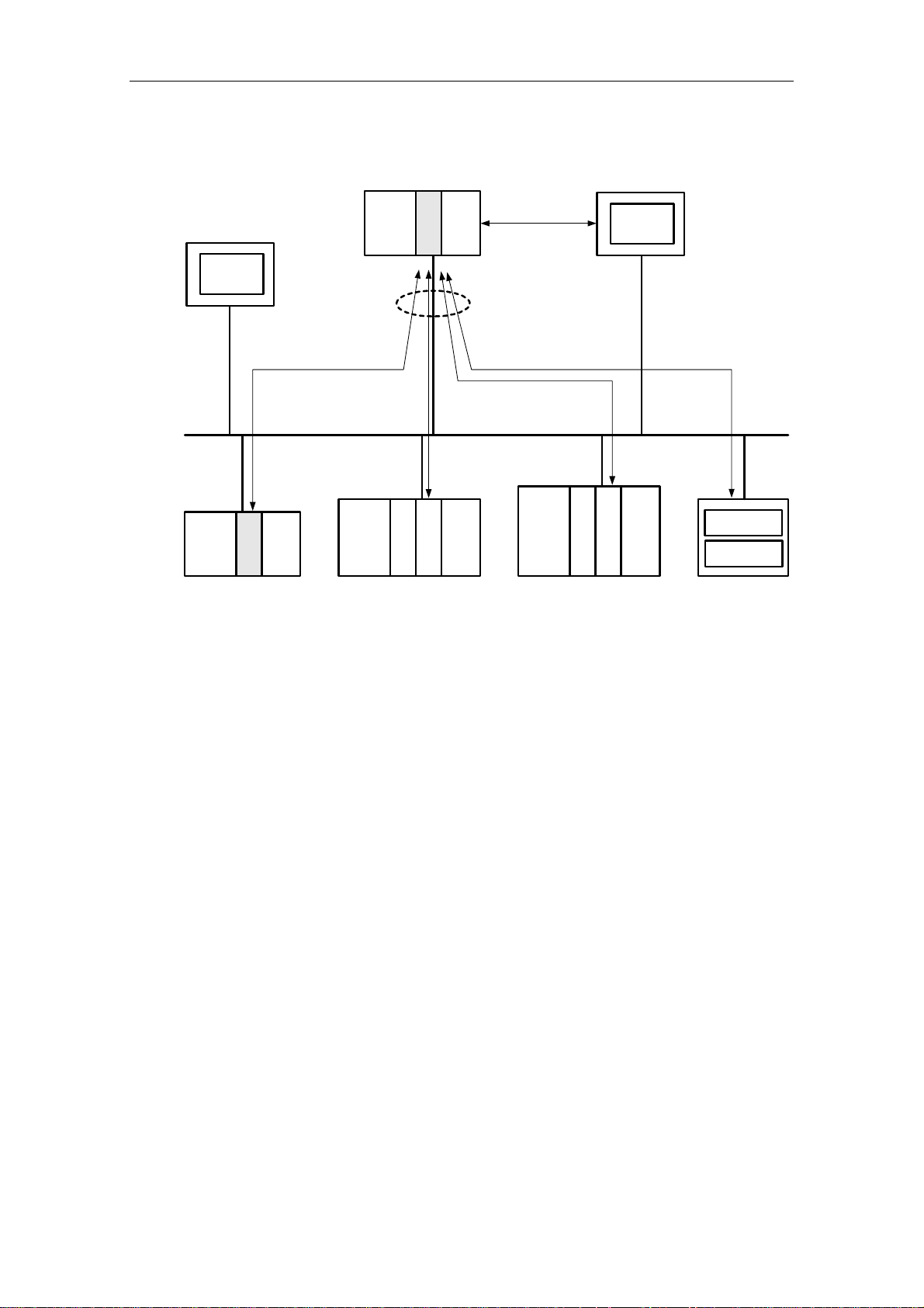
Overview
S7-200
PC
BOOTP-
Server
max. 8 x
xput / xget read / write
...
CPU 22x
CP 243-1/IT
S7-200 S7-300 S7-400
CPU 22x
CPU 3xx
...
CP 243-1 IT
......
CP 343-1/IT
1 x
PC
Micro/WIN
Ethernet
OPC-Server
CPU 4xx
......
CP 443-1/IT
OPC-Client
PC
Fig. 1 System overview
A CPU 22x with CP 243-1 IT can communicate both with other S7-200, S7-300
and S7-400 systems and with an OPC server. A maximum of 8 connections (see
Fig. 1) are possible in addition to a STEP 7 Micro/WIN connection.
Configuring and programming connections for S7 stations
To configure communication between an S7-200 and an S7-300, S7-400 or an
OPC server, you will need both STEP 7 Micro/WIN 32 (starting with version 3.2.3)
and STEP 7 (starting with version 5.1 with service pack 3 or higher, with NCM for
Industrial Ethernet).
The S7-200 station is configured and programmed with STEP 7 Micro/WIN 32. You
will need STEP 7 with NCM for Industrial Ethernet to configure and program the
S7-300 or S7-400 or the OPC server.
CP 243-1 IT
J31069-D0429-U001-A0-7618 19
Page 20

Features and Functions 03/03
Data communication via Industrial Ethernet
Data communication via the CP 243-1 IT is based on Ethernet and is thus not deterministic (i.e., specific response times are not guaranteed). 10 and 100-Mbit networks are supported in full and half-duplex.
In addition, the CP 243-1 IT supports the auto-negotiation function for automatically
negotiating the operating mode and the transmission speed to be used. The mode
and the transmission speed can also be permanently specified by the user when
configuring the CP 243-1 IT. If the CP 243-1 IT doesn't have a valid configuration, it
always uses "auto-negotiation" mode.
Note
Auto-negotiation mode only works when all connected network components support this mode.
Industrial Ethernet and TCP/IP do not allow time-deterministic data flow. There is
no way to know when a geographically remote CPU will execute the requested
jobs. The responses of the geographically removed CPU are asynchronous to the
CPU cycle of the local S7-200 CPU. This is why TCP/IP-based communication is
only partly suitable for use in widespread applications with time requirements (e.g.,
control circuits, cyclic precisely timed scanning).
CP 243-1 IT
20
J31069-D0429-U001-A0-7618
Page 21

03/03 Features and Functions
S7 communication
The XPUT and XGET S7 services are used to communicate data between two
controllers. The CP 243-1 IT can be used both as client and as server.
Communication between a CP 243-1 IT and an OPC server running on a PC/PG
uses the READ and WRITE S7 services. The CP 243-1 IT is always the server
here. Other S7 services (e.g., the service for automatic scanning of objects on an
S7-200 - DBs, and so on) are not supported.
The following data types or data areas are supported by the CP 243-1 IT.
CP 243-1 IT as client
Read and write accesses
• Data type is always BYTE.
• Only variables can be accessed on the local system.
• Accessible memory areas on the partner system are inputs, outputs, markers
and variables with an S7-200 as partner.
• Accessible memory areas on the partner system are inputs, outputs, markers
and data areas with an S7-300 or an S7-400 as partner.
CP 243-1 IT a server
Write accesses
• Data type is BOOL, BYTE, WORD or DWORD.
• Use of data types CHAR, INT, DINT and REAL depends on the firmware status
of the S7-200 CPU being used.
• Accessible memory areas on the local system are inputs, outputs, variables,
markers and status bits.
Read accesses
• Data type is BOOL, BYTE, WORD or DWORD.
• Use of data types CHAR, INT, DINT and REAL depends on the firmware status
of the S7-200 CPU being used.
• Accessible memory areas on the local system are inputs, outputs, variables,
markers, system area and status bits.
Note
When an S7-300 or S7-400 is the server on a client running on an S7-200 system,
the CP 243-1 IT expects this server to always behave passively. This means that,
in such cases, the S7-300 or S7-400 system is not allowed to send S7 jobs to the
S7-200 system.
Communication with STEP 7 Micro/WIN 32
With communication between a CP 243-1 IT and STEP 7 Micro/WIN 32, the CP
243-1 IT is always the server. STEP 7 Micro/WIN 32 is always the client here.
CP 243-1 IT
J31069-D0429-U001-A0-7618 21
Page 22

Features and Functions 03/03
Backplane bus communication
All accesses to all data areas of the S7-200 CPU are always possible. The read
and write accesses are not dependent on whether the CPU is in RUN, TERM or
STOP status.
CP 243-1 IT
22
J31069-D0429-U001-A0-7618
Page 23
03/03 Features and Functions
2.3 IT Communication
2.3.1 Preliminary Remarks
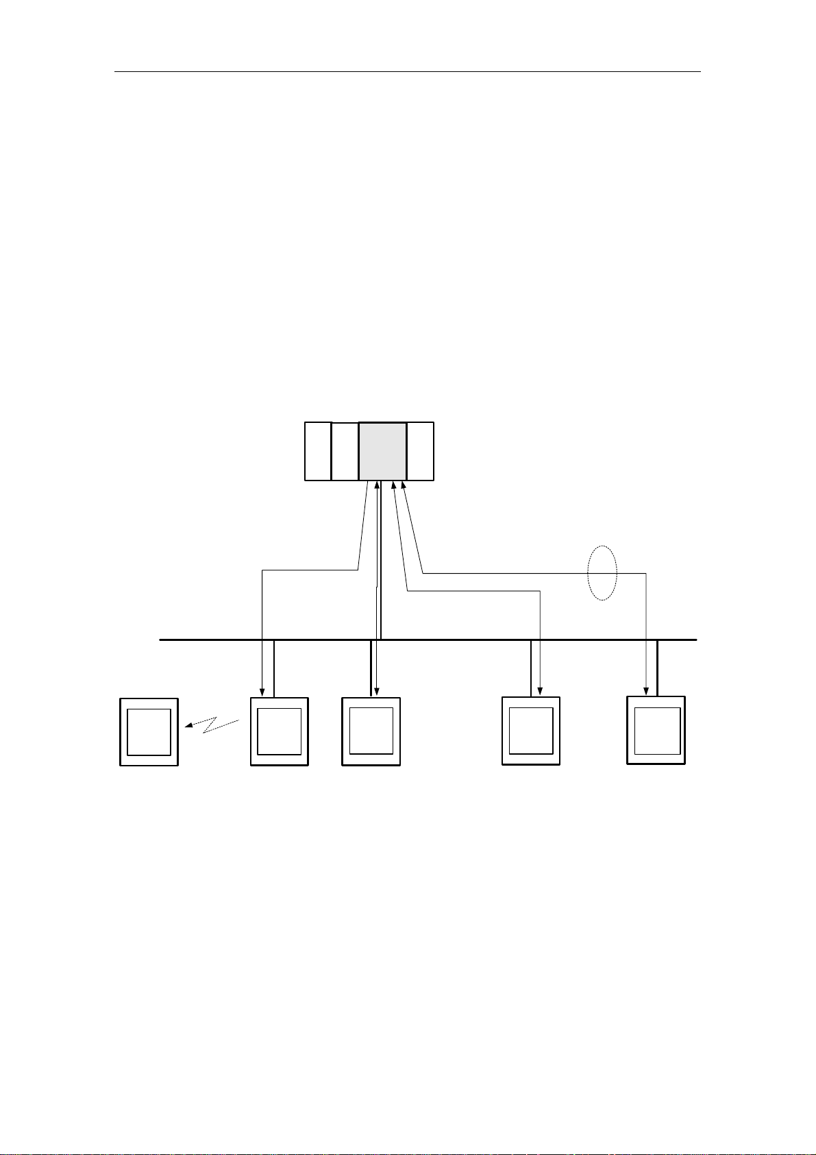
In addition to S7 communication via Industrial Ethernet, the CP 243-1 IT also supports the services XPUT/XGET and READ/WRITE parallel to a variety of IT functions. These include data communication via FTP, sending e-mails, and the capability of permitting up to four Web browsers to access data and status information
on the S7-200 system at the same time. See Fig. 2.
Sending an e-mail or active file access via FTP are initiated by the S7-200 user
program. Only one job at a time can be active for each of these two functions. Not
until the CP 243-1 IT has positively or negatively acknowledged the job can the
user program start another job.
S7-200
E-MailServer
PC
Handy
PC
E-Mail-
Server
SMTP
CPU 2xx
...
FTP
FTP-
Client
PC
S7-200
S7-300
S7-400
...
CP 243-1 IT
Fig. 2 Overview of the IT functions
HTTP
PC
S7-200
S7-300
S7-400
FTP
FTP-
Server
4x
Ethernet
HTTP-
Browser
PC
CP 243-1 IT
J31069-D0429-U001-A0-7618 23
Page 24

Features and Functions 03/03
2.3.2 Types of Communication
In addition to the S7 communication relationships described in chapter 2.2.2, the
CP 243-1 IT offers four types of IT communication relationships which can be used
individually or in combination.
1. Communication with an e-mail server
2. Communication with an FTP client located in a geographically remote system
3. Communication with an FTP server. Such a server is usually located in a geographically remote system. However, a coupling to the FTP server running on
the CP 243-1 IT of the local S7-200 system is also possible.
4. Communication with up to four Web browsers running on geographically remote
systems
CP 243-1 IT
24
J31069-D0429-U001-A0-7618
Page 25

03/03 Features and Functions
2.3.3 E-Mail
How it works
The SMTP protocol controls the transmission of e-mails. An e-mail consists of one
or two address fields, a subject field and a field for the actual text message.
The text message consists of ASCII characters. The text may contain placeholders
for variables which reference a data value of the local S7-200 system. When the email is sent, the CP 243-1 IT reads each such value from the local S7-200 CPU
and inserts it in the desired format at the specified location in the message. The CP
243-1 IT makes it possible to send e-mails preconfigured by a user program to an
e-mail server already specified via IP address and an port during the configuration
phase. The e-mail server then sends the e-mail to the e-mail recipient specified in
the address field of the e-mail.
The e-mail server specified in the configuration by an IP address and a port number must be located in the subnetwork of the CP 243-1 IT or be able to be accessed via a gateway. If this e-mail server cannot be accessed, the e-mail is sent
to a substitute e-mail server which is also specified when the CP 243-1 IT is configured. If this substitute e-mail server is also not accessible, an appropriate error
message is generated.
Caution
The CP 243-1 IT only monitors whether an e-mail could be delivered to the configured e-mail server. It is unable to tell whether this e-mail was forwarded to and
read by the specified recipient.
Note
Since memory areas of the S7-200 CPU must be read out in accordance with the
configuration when an e-mail is sent, a reset in between or power failure of the S7200 CPU may cause the e-mail transmission to be terminated altogether before it
can even be sent.
This means that a message that an S7-200 CPU reset has occurred cannot be
sent via e-mail.
The CP 243-1 IT does not support the receipt of e-mails. The e-mails and the address parameters of the e-mail server are configured by STEP 7 Micro/WIN 32.
CP 243-1 IT
J31069-D0429-U001-A0-7618 25
Page 26

Features and Functions 03/03
Note
Before e-mails can be sent from the CP 243-1 IT, you must make sure that a functioning e-mail server can be accessed from there.
General accessibility of an e-mail server can be tested with the HTML page
"sendmail.htm," among others, which is included with the CP 243-1 IT (see chapter
2.3.6).
Configuration
Configuration of the e-mails and the address parameters of the e-mail server is
performed with the Internet wizard of STEP 7 Micro/WIN 32. The configuration data
entered here are stored permanently in a file with the ending .edb in the file system
of the CP 243.1 IT. Transmission of these data from the system on which the configuration was prepared with STEP 7 Micro/WIN 32 to the CP 243-1 IT is handled
via FTP.
Up to 32 e-mails can be configured. Each e-mail text may consist of up to 1024
characters.
The structure of each e-mail is shown below.
− E-mail number
This number can be used to reference a configured e-mail by the S7-200
user program.
− Receiver address
The e-mail address of the receiver. This address must always be specified.
− Additional receiver address
The address of a recipient who is to receive a copy of the e-mail. This address does not have to be specified.
− Subject
A short description of the e-mail. The subject must always be specified.
− E-mail text including placeholders and formatting characters. The actual in-
formation to be transferred is located here.
Each address field may only contain one receiver address. When an e-mail is to be
sent to several recipients, a distribution list must be set up on the e-mail server and
this list must be specified as the e-mail receiver.
In addition to the control characters for the placeholders of data values, the following format characters are supported in the e-mail text.
− \n Line feed
− \t Tabulator
CP 243-1 IT
26
J31069-D0429-U001-A0-7618
Page 27

03/03 Features and Functions
Note
The maximum length of the e-mail text of 1024 characters refers to the actual message text including all embedded placeholders and all format characters ("\n" and
"\t").
If the maximum permissible length of 1024 characters is exceeded by resolution of
the placeholders when an e-mail is sent, the e-mail text is truncated after 1024
characters and an appropriate error message is returned. The truncated e-mail is
then transferred, however.
Conversion procedures such as MIME or UUENCODE are not supported. In addition, files cannot be appended to e-mails.
The e-mail function of the CP 243-1 IT can always be activated or deactivated with
the configuration.
Communication partners
In addition to conventional PCs, all terminals with e-mail capability are in principle
possible e-mail recipients (e.g., cell phones or FAX machines).
Performance/general conditions
Sending of e-mails is subordinate to S7 communication.
Reaction times when sending an e-mail depend on the configuration and cannot be
specified in general. The greater the number of simultaneous S7 connections and
the larger the amount of data to be transmitted over these connections, the longer
it takes to process and send e-mails.
Caution
The placeholders embedded in the e-mail text are read out individually from the
S7-200 CPU. Only one such value can be transferred per S7 cycle from the S7200 CPU to the CP 243-1 IT. This means that the time needed to set up an e-mail
depends on the amount of data to be included, the cycle time of the S7-200 CPU
and the load of the backplane bus.
2.3.4 FTP Server
How it works
The FTP server of the CP 243-1 IT can be used, among others, to transfer Web
files and configuration files from a geographically remote FTP client via Ethernet to
the file system of the CP 243-1 IT and to read them there.
In this case, the FTP client always initiates the data transfer. The FTP server of the
CP 243-1 IT never initiates FTP transmissions itself.
CP 243-1 IT
J31069-D0429-U001-A0-7618 27
Page 28

Features and Functions 03/03
All types of files can be transferred to the file system of the CP 243-1 IT. Relevance of these files to operation of the CP 243-1 IT is not checked.
Caution
BINARY-type transmission should be used to transfer files between the FTP server
of the CP 243-1 IT and a geographically remote FTP client. The transmission type
must be set on the FTP client side.
Note
Since the CP 243-1 IT does not provide the time, the files stored on or read from
the CP 243-1 IT via FTP all have the date 01.01.1980 and the time 00:00.
Access protection
FTP is a protocol for which the user must authenticate himself before gaining access to the FTP server. This requires a user name and a password which is valid
on the server. After a connection between the FTP client and the FTP server of the
CP 243-1 IT is established, the user name and related password must be entered.
After successful authentication, the user can then access the file system of the CP
243-1 IT. He can move through the directory tree, transmit files and manage directories.
Up to 8 users as well as an administrator can be configured for the CP 243-1 IT.
The administrator is distinguished from the up to 8 users with special rights and the
location at which the fixed user name and the related password are stored.
The user names and passwords are configured with STEP 7 Micro/WIN 32. The
configuration file created by the Internet wizard to be used here is transferred with
FTP to the CP 243-1 IT and stored permanently in the file system there in a file
with the ending .udb. The user name and the password of the administrator are required before the user configuration can be transferred to the CP 243-1 IT.
Note
The CP 243-1 IT does not support an FTP access without specification of a user
name or password.
Auto logout
Simultaneous access of several FTP clients to the FTP server of the CP 243-1 IT is
not supported.
The FTP server is equipped with an auto logout routine to prevent it from being
blocked by an undefined connection termination of an FTP client.
If the FTP server located on the CP 243-1 IT is connected with an FTP client and a
second FTP client wants to establish a connection to the FTP server, the server
checks to determine whether there was FTP-based communication between it and
the first FTP client during the last 60 seconds. If not, the connection to the fist FTP
client is disconnected and the second FTP client's request to establish a connection is accepted. Otherwise, the connection to the first FTP client is continued and
the second FTP client's request for a connection is rejected.
CP 243-1 IT
28
J31069-D0429-U001-A0-7618
Page 29

03/03 Features and Functions
Supported FTP commands
After the HELP command is entered in the console box of the FTP client, a list of
the FTP commands supported by this client usually appears. While these commands are being executed, they can then be converted internally by the FTP client
into subcommands and sent to the FTP server.
Some FTP clients on the market offer additional commands which are not included
in the RFC959 standard or whose specification is not generally binding. You cannot be sure whether the FTP server on the CP 243-1 IT supports each of these
commands.
Communication partners
All FTP clients which communicate via Ethernet and which comply with RFC959
standards are always considered possible communication partners of the FTP
server located on the CP 243-1 IT. This means communication is not only possible
with PC-based FTP clients but also with S7-200, S7-300 or S7-400-supported FTP
clients, for instance.
Performance/general conditions
FTP communication is subordinate to S7 communication. This means that the reaction times of FTP communication depend on the particular configuration and
cannot be generally specified in advance.
Note
Only one FTP client may access the FTP server at a time. When the FTP server of
the CP 243-1 IT is accessed by the S7 user program via the FTP client function, a
geographically remote FTP client cannot be accessed. The reverse also applies.
2.3.5 FTP Client
How it works
The FTP client of the CP 243-1 IT can be used to transfer parts of the DB in an S7200 system to the file system of an FTP server, or the contents of a file can be copied there to the DB of the local S7-200 system.
A distinction can be made as to whether a file is to be completely or only partially
transferred. The number of bytes to be transmitted can be specified in a read or
write job.
When 0 is specified as the number of bytes to be transferred in a write job, an
empty file with the name specified in the write job is set up in the file system of the
addressed FTP server. A length of 0 in a read job means that the specified file is
completely transmitted to the DB of the local S7-200 system if this does not exceed
its storage space. If the number of bytes to be read is specified for a read job, this
must match the length of the file to be read. If not, the CP 243-1 IT reports an error
when the read job is executed.
CP 243-1 IT
J31069-D0429-U001-A0-7618 29
Page 30

Features and Functions 03/03
With the help of the FTP client, it is possible to delete files in the file system of an
FTP server from the local S7-200 system.
During the transmission with FTP, the files to be exchanged are not changed and
the data therein are not converted. All data to be transferred are treated as if they
were in byte format. The data to be written are stored by byte in the specified file.
The FTP client of the CP 243-1 IT always initiates the file transfer, triggered by the
S7-200 user program. An FTP server itself does not generate FTP requests.
The CP 243-1 IT only accepts one FTP client request from the S7-200 user program at a time. As soon as this is completely processed, the CP 243-1 IT prepares
a positive or negative acknowledgment. Not until this happens can the S7-200 user
program issue a new FTP client job.
The FTP servers specified in the configuration with their IP address must be located in the subnetwork of the CP 243-1 IT or must be accessible via a gateway.
Caution
The data transferred from or to the memory of the S7-200 CPU via FTP are transmitted in binary mode. There is no conversion or formatting of these data. The data
to be transferred are not stored permanently on the CP 243-1 IT.
Configuration
The FTP jobs are configured with the Internet wizard of STEP 7 Micro/WIN 32. The
configuration data entered here are permanently stored in the file system of the CP
243-1 IT in a file with the ending .fdb. Transmission of these data from the system
on which the configuration was prepared with STEP 7 Micro/WIN 32 to the CP 2431 IT is handled via FTP.
Up to 32 FTP jobs can be predefined with one file transaction each. Each of these
jobs is described with the following parameter record.
− FTP job number
Every configured FTP job can be referenced from the S7-200 user program
with this number.
− IP address on the FTP server
IP address of the system whose file system is to be accessed
− User name on the FTP server
The login on the FTP server takes place under this name. This means that
the name specified here must have access rights for the addressed FTP
server.
− Password for on the FTP server
The encrypted password specified here is used to log in on the FTP server.
− Path name of the applicable file
The file name including the complete path must be specified here.
− Job type to be executed. Possible job types are:
− Write to file system of the FTP server
− Read from file system of the FTP server
− Delete files from file system of the FTP server
CP 243-1 IT
30
J31069-D0429-U001-A0-7618
Page 31

03/03 Features and Functions
− Start address and length of the data in the data block
Specify here the address starting at which the data to be read are to be
stored in the memory of the S7-200 CPU or the address starting from which
the data to be written are to be sent to the FTP server, and how many bytes
are to be transmitted.
Note
The connection to an FTP server always uses port 20 for data communication and
port 21 for transmission of commands.
Note
The FTP client supports file names in upper case/lower case letters if the FTP
server with which the data are to be exchanged and the applicable file system
permit file names with upper case/lower case letters.
Caution
During configuration, the Internet wizard of STEP 7 Micro/WIN 32 only checks the
correctness of the FTP client configuration's syntax. Checks of this configuration's
semantics cannot be performed until the file transaction takes place.
The FTP client function of the CP 243-1 IT can always be activated/deactivated
with the configuration.
Communication partners
All FTP clients which communicate via Ethernet and which comply with RFC959
standards are always considered possible communication partners of the FTP client. This means communication is not only possible with PC-based FTP servers
but also with FTP servers running on S7-200, S7-300 or S7-400 systems, for instance.
Performance/general conditions
Note
If data from a remote FTP server is stored in the local S7-200 CPU, it is up to the
user to ensure that this data is not stored in memory areas which are already being
used. The CP 243-1 IT only performs rudimentary security checks for this.
The CP 243-1 IT does not ensure that all data to be transferred originate from one
cycle of the local S7-200 CPU or are all effective simultaneously in one cycle since
the transmission of these data to and from the local S7-200 CPU is asynchronous
in time to the cycle of the local S7-200 CPU and the duration cannot be predicted
in general terms.
With FTP write jobs, the CP 243-1 IT can read 246 bytes per cycle from the memory of the S7-200 CPU. With FTP read jobs, the CP 243-1 IT can even transfer up
to 254 bytes per cycle to the memory of the S7-200 CPU.
CP 243-1 IT
J31069-D0429-U001-A0-7618 31
Page 32

Features and Functions 03/03
To ensure consistency with large amounts of data, appropriate measures must be
provided in the S7-200 application program.
When a transmission between the FTP client of the CP 243-1 IT and an FTP
server is interrupted, only part of the transferred data may have been stored on the
destination system. In such cases, an error message is output by the S7-200 user
program. The transaction is not repeated automatically.
On the CP 243-1 IT, data communication via FTP is subordinate to S7 communication. Reaction times vary with the particular configuration as well as the length of
the S7-200 application program and generally cannot be predicted in advance.
Note
The file DB routine of communications processors CP 343-1 IT and CP 443-1 IT is
not supported by the CP 243-1 IT. The CP 243-1 IT reads or writes one binary image of the data block from/to a file. This file contains no other information on
length, source address, and so on.
CP 243-1 IT
32
J31069-D0429-U001-A0-7618
Page 33

03/03 Features and Functions
2.3.6 HTTP Server
Fundamentals
Java Applets are little application programs prepared in the programming language
Java. At a browser's request, such Applets are usually transferred from an HTTP
server to a browser and executed there. The browser must have Java capability
and must permit execution of Applets. All today's browsers usually offer Java capability. They can usually be configured to allow execution of Java Applets.
Java Beans are software components with a standardized interface written in the
programming language Java. It is easy to link these Beans into conventional Java
development environments and connect them with graphic tools for complete Java
applications or Java Applets.
How it works
The functionality of an HTTP server integrated on the CP 243-1 IT permits the user
to access the S7-200 system with one of the popular Web browsers to read status
information or read/change process values, for instance.
Predefined HTML pages and Java Applets stored in the file system of the CP 2431 IT are available to the user. In addition, the user can prepare his own HTML
pages or Java Applets and transfer them to the file system of the CP 243-1 IT with
the help of an external FTP client.
Java Beans are provided on the documentation CD of the CP 243-1 IT for simple
creation of Java Applets. They can be copied from there to a development computer and then, with the aid of a Java development environment (e.g., "Visual Age"
from IBM), linked to your own Java Applets. The Beans included with the CP 243-1
IT are Java components which provide functions which can always be used when
creating a user interface environment. This not only includes functions for read or
write accesses to individual process values but also graphic functions for visualization of such values.
The document "SIMATIC NET IT-CP Programming Help" included with the CP
243-1 IT on the documentation CD contains a more detailed description of the individual Beans. A precise description of how to combine these Beans into Java Applets is provided. If the Java Beans described in this document are used with the
purpose of accessing an S7-200 via a CP 243-1 IT, symbolic addressing cannot be
used in these Beans.
Using the HTML pages and Java Applets supplied in the file system of the CP 2431 IT, the following data areas and data types of the S7-200 system can be accessed.
− Data types
BOOL, BYTE, CHAR, WORD, INT, DWORD, DINT and REAL
− Data areas
Inputs (I), outputs (Q), markers (M), variable area (V) and special markers
(SM)
CP 243-1 IT
J31069-D0429-U001-A0-7618 33
Page 34

Features and Functions 03/03
Note
The availability of the data types CHAR, INT, DINT and REAL depends on the
firmware status of the S7-200 CPU being used.
Access protection
Calling the HTML pages stored in the file system of the CP 243.1 IT with a Web
browser is not subject to access protection. Such protection is not activated until
status or process variables are accessed from a Web browser or when an attempt
is made to send a test e-mail via the applicable HTML page.
The basic access authentication scheme described in RFC2617 is used as the authentication routine for all password-protected HTML pages.
In this case, the user must authenticate himself with his user name and the related
password. Access to the HTTP server of the CP 243-1 IT is then granted or refused depending on the access rights assigned to the user by user administration.
The HTTP server of the CP 243-1 IT can always be activated/deactivated with the
configuration.
HTML pages on the CP 243-1 IT
The file system of the CP 243-1 IT contains already prepared HTML pages in English which already supply status and diagnostic information via integration of the included Java Applets. These HTML pages can be edited or further processed by the
user with an HTML editor such as Netscape Composer or a standard editor.
The following table lists the already predefined HTML pages which are included in
the file system of the CP 243-1 IT or which can be dynamically assembled by the
CP 243-1 IT as soon as a request from a Web browser is received. These HTML
pages have been optimized for monitor screen settings.
• Resolution: 1152 x 864
• Size of type: No type fonts
We recommend using the Internet Explorer 6.0 from Microsoft as your Web
browser.
CP 243-1 IT
34
J31069-D0429-U001-A0-7618
Page 35

03/03 Features and Functions
HTML Page Call Meaning
http://<destination IP address>/index.htm Start page of the CP 243-1 IT with links to further in-
ternal and external HTML pages
If only <destination IP address> is specified on the
Web browser, index.htm is automatically opened.
http://<destination IP address>/__S7Sys/rack Indicates the setup of the S7-200 destination system.
In addition, the available status information for each
module is shown.
This page is not automatically updated. To indicate the
present status of the S7-200 system correctly, this
page must be loaded again to the Web browser.
Note:
"Rack" is not an HTML page located physically in the
file system of the CP 243-1 IT. When the adjacent address is called from a Web browser, the HTTP server
dynamically sets up an HTML page with the systemspecific information. The layout of this page cannot be
changed by the user.
http://<destination IP address>/__S7Sys/sendmail.htm
http://<destination IP address>/__S7Sys/it_info Present status of the CP 243-1 IT. This page indicates
Indicates a page with which a test e-mail can be sent
to a specified receiver. The address fields (TO, CC)
and the fields of the subject and the text are limited to
a maximum of 64 characters each.
When the page is called, the user is asked to authenticate himself with a user name and a password.
Only the administrator is authorized to send a test email. The errors which can occur are described in
chapter 6.3.
data relevant to operation of the CP 243-1 IT. Some
examples are listed below.
• Module name
• Firmware and hardware version
• Network parameters
• Status of the Micro/WIN connection
• Configuration and availability of S7, FTP and
e-mail connections
• Information pertaining to the file system
This information is only provided to users authorized
by user administration. These users must authenticate
themselves with a user name and a password.
This page is not automatically updated. To correctly
indicate the present status of the CP 243-1 IT, the Web
browser must load this page again.
Note:
"It_info" is not an HTML page located physically in the
file system of the CP 243-1 IT. When the adjacent address is called from a Web browser, the HTTP server
dynamically sets up an HTML page with the systemspecific information. The layout of this page cannot be
changed by the user.
CP 243-1 IT
J31069-D0429-U001-A0-7618 35
Page 36

Features and Functions 03/03
HTML Page Call Meaning
http://<destination IP address>/examples/info.htm
http://<destination IP address>/examples/statuschart.htm
General information page of the CP 243-1 IT with external links to the IT CP and SIMATIC NET Web page.
An internal link refers to the Web page readme.htm.
This page can be used to read process values of the
S7-200 system.
The data or data areas to be read are designated by
address.
Remember that the values shown on this page are
read out cyclically. Depending on the cycle time, an indicated value may differ from the value actually in the
S7-200 system at the same time.
Table 1 Predefined HTML pages
Note
Some of the HTML pages included with the CP 243-1 IT link in Java Applets. To
ensure that this functions correctly, the execution of Java Applets must be enabled
on the Web browser.
Communication partners
All HTTP clients (e.g., Web browsers) represent potential communication partners
of the HTTP server. The HTTP server of the CP 243-1 IT supports simultaneous
access of up to 4 Web browsers.
The TCP/IP connection to the HTTP server is always handled by port 80.
Performance/general conditions
On the CP 243-1 IT, HTTP communication is subordinate to S7 communication.
Reaction times vary with the particular configuration and cannot be predicted generally in advance.
The HTTP server located on the CP 243-1 IT has four communication channels
(i.e., it can process up to four requests at the same time). When a request arrives
at the HTTP server when all four communication channels are occupied, the request is rejected. New requests cannot be processed until at least one of the four
communication channels is free again.
CP 243-1 IT
36
J31069-D0429-U001-A0-7618
Page 37

03/03 Features and Functions
2.4 File System
How it works
A file system is available on the CP 243-1 IT to permanently store Web and configuration files. This file system uses flash memory technology and offers a storage
capacity of 8 Mbytes minus the memory needed for administration of the flash file
system.
Note
The amount of memory which is actually available in the file system can be called
with HTML page "CP 143-1 IT Information" (included with the CP 243-1 IT) via a
Web browser under the address:
http://<destination IP address>/__S7Sys/it_info.htm
Due to the formatting of the file system, the amount of memory specified on this
page cannot always be fully utilized.
Access
The file system supports path and file names up to a total length of 254 characters.
The drive name of the flash file system (/flash:) is also added to the 254 characters. This means that, after the drive name is deducted, 247 characters remain for
a maximum path including the file name. The actual file name and every name of a
directory can have a maximum length of 99 characters. The maximum nesting
depth of the directories is 49.
The following characters may not be used in either file or directory names:
\ ; / ; < ; > ; “ ; : ; * ; ?
Note
We recommend always storing files in suitable subdirectories and not in the root directory.
Since the CP 243-1 IT has neither date nor time, all files stored in the file system of
the CP 243-1 IT have the date 01.01.1980 and the time 00:00.
The file system can only be accessed with the FTP server of the CP 243-1 IT. The
file system does not distinguish between upper case and lower case letters.
CP 243-1 IT
J31069-D0429-U001-A0-7618 37
Page 38

Features and Functions 03/03
Restrictions
Caution
The life of a file system based on flash memory technology is primarily determined
by the number of write or deletion operations performed on it. Obviously such a file
system is not suited to highly cyclic write or delete operations.
The file system of the CP 243-1 IT uses an internal optimization routine to assign
all available locations of the flash memory uniformly. When individual memory locations fail due to old age, these locations are detected and marked internally as unusable. Despite this, highly cyclic write or delete accesses to the file system of the
CP 243-1 IT should be avoided.
Structure of the file system
Directory Meaning
/flash:
/flash:/applets
/flash:/config
/flash:/examples
/flash:/__S7Sys
/flash:/user
The root directory of the file system contains a predefined homepage of
the CP 243-1 IT (index.htm) which you can adjust to your specific requirements. This homepage requires files from the directories /__S7Sys and
/examples.
When storing user files, appropriate subdirectories should always be set
up to store these files under.
This directory contains several *.jar files which are required for S7 Applets.
These *.jar files contain the Java Beans (included with the CP 243-1 IT on
the documentation CD) in compressed format.
This directory should not be deleted.
This directory contains the configuration files of the CP 243-1 IT which
were created by STEP 7 Micro/WIN 32.
This directory should not be deleted.
This directory contains HTML files of the CP 243-1 IT which can be accessed via the predefined HTML start page with links. Some HTML pages
contain Java Applets.
This directory contains important, write-protected system pages. These
pages are needed, among others, to assemble the dynamic HTML pages
rack and it-info.
This directory should not be deleted.
Only the administrator has access to this directory.
User-defined HTML pages and user data should be stored in this directory.
Table 2 Directory structure of the CP 243-1 IT
CP 243-1 IT
38
J31069-D0429-U001-A0-7618
Page 39

03/03 Features and Functions
2.5 User Administration
How it works
When process data are exchanged via Intranet/Internet services, security becomes
very important.
To ensure security, user administration with graduated password protection was integrated on the CP 243-1 IT. Up to 8 users can be configured with the Internet wizard of STEP 7 Micro/WIN 32. During configuration, each of these users is assigned
a user name, a password and certain access rights. These access rights control
authorization to access process data and the file system.
The configuration of up to 8 users is stored on the file system of the CP 243-1 IT in
a file with the ending .udb. For security's sake, the passwords assigned during the
configuration are stored encrypted in this file.
Note
The user administration of the CP 243-1 IT does not support user groups.
Administrator
In addition to these 8 users, the user administration of the CP 243-1 IT recognizes
another user with special access rights - the administrator. The administrator is the
only user who may access the directory /__S7Sys and store the .udb configuration
file for user administration via FTP in the file system of the CP 243-1 IT.
The user name and the password of the administrator are configured with the
Internet wizard of STEP 7 Micro/WIN 32. However, unlike the configuration of the 8
users, this configuration is not stored in the file system of the CP 243-1 IT but on
the S7-200 CPU. Before the configuration of the 8 users can be transferred via
FTP to the file system of the CP 243-1 IT, an administrator with user name and
password must be set up for the CP 243-1 IT.
Granting of access rights
Access rights are organized by rights for the administrator and rights for the 8 other
users.
The following user rights can be configured for the administrator.
• Access to all IT functions
• Access to the FTP server
CP 243-1 IT
J31069-D0429-U001-A0-7618 39
Page 40

Features and Functions 03/03
The following user rights can be configured for the 8 other users.
• Read access to process data of the S7-200 system from a Web browser
• Read and write access to process data of the S7-200 system from a Web
browser
• Read access to status information of the CP 243-1 IT from a Web browser
• Access to the file system via the FTP server with the following restrictions
− Only the administrator may access the directory /__S7Sys.
− Only the administrator may store the configuration file for the user ad-
ministration (.udb file) in the file system of the CP 243-1 IT.
Note
HTML pages can be called by a Web browser without password protection. Password protection is not activated until process values of the S7200 system are accessed by such pages.
Note
We recommend not allowing the 8 configurable users access to the FTP. If a user
is permitted access to the FTP, this user has the opportunity to change the configuration data stored in the file system of the CP 243-1 IT.
Note
To keep configuration effort as low as possible with regard to user administration,
we recommend using abstract users with special rights (e.g., "commissioning,"
"maintenance," or "manufacturing") instead of natural users (e.g., "Jack Sprat").
Character set/number for entering user name/password
Role User Name Password
Administrator 1 to 16 characters 8 to 16 characters
User 1 to 32 characters 1 to 32 characters
Table 3 Length of the user names and passwords
All ASCII characters between 0x21
password.
and 0x7E
HEX
HEX
can be used for user name and
CP 243-1 IT
40
J31069-D0429-U001-A0-7618
Page 41

03/03 Features and Functions
2.6 Security
2.6.1 Configuration
Part of the configuration of the CP 243-1 IT is retentively stored on the S7-200
CPU and part in the file system of the CP 243-1 IT. The validity of the portion of the
configuration stored on the S7-200 CPU is secured by a CRC routine. In contrast,
no CRC routine is used for the portion of the configuration stored in the file system
of the CP 243-1 IT.
While storing a configuration on the CP 243-1 IT, STEP 7 Micro/WIN 32 calculates
a CRC checksum. This checksum is stored together with one part of the configuration. While reading out the portion of its configuration stored on the S7-200 CPU,
the CP 243-1 IT checks this checksum so that it can detect undesired changes in
the stored configuration data.
This CRC routine can also be deactivated, however. The configuration can then be
changed manually or by an S7-200 user program.
Caution
Since, after the CRC check is disabled, the CP 243-1 IT is no longer able to check
the configuration data for consistency concerning desired or undesired changes,
there is no guarantee whatsoever that the CP or the components connected to the
network will function correctly.
Caution
The CP 243-1 IT recognizes that the CRC is disabled by a special value of a byte
in its configuration. If precisely this value is set in the configuration either coincidentally or intentionally, this may disable the CRC test. This is why we strongly
recommend only creating the configuration with the Internet wizard integrated in
STEP 7 Micro/WIN 32 and checking the S7-200 program for memory operations
which affect in the data area in which the configuration data of the CP 243-1 IT are
stored.
CP 243-1 IT
J31069-D0429-U001-A0-7618 41
Page 42

Features and Functions 03/03
2.6.2 Data Security
The CP 243-1 IT is a physical connection between the Internet, Ethernet and S7200 backplane bus. It offers:
• No protection against intended or accidental manipulations of the data areas
and/or system states of the local or geographically remote CPUs
• No firewall functionality
Possible Internet access by the CP 243-1 IT to data stored on the S7-200 CPU always harbors the danger of misuse. For this reason, it is a good idea to change the
passwords assigned to the various users at regular intervals.
Additional information on the subject of security can be found in the document on
information technology for the Siemens AG automation technology.
The CP 243-1 IT disconnects an active STEP 7 Micro/WIN 32 connection when no
STEP 7 Micro/WIN job was sent to the CPU during the last 50 seconds. This prevents the Micro/WIN server on the CP 243-1 IT from being blocked by network errors which in turn prevents a new connection to STEP 7 Micro/WIN 32.
Note
Server accesses via the CP 243-1 IT to the S7-200 CPU are possible both in RUN
and STOP modes of the CPU. In STOP mode, however, program variables or I/O
values are not updated.
Caution
The user name and related password required to log in on an FTP server are always transmitted unencrypted over the network in accordance with valid general
specifications of the FTP protocol.
2.6.3 Communication Security
The CP 243-1 IT is equipped with a "Keep Alive" routine. This means that the CP
243-1 IT is able to automatically recognize the failure of a communication partner
or the applicable connection within a configurable period of time.
The Keep Alive time which is specified when the CP 243-1 IT is configured is the
time after which this internal routine is started. The routine attempts to reach the
communication partner. It takes approx. 10 seconds for this routine to be performed. If the communication partner cannot be reached during this time, the CP
243-1 automatically concludes the connection to this partner. If the CP 243-1 IT is
the client, it then attempts to establish this connection again. Failure of the communication partner is reported to the user with the routines described in chapter 6.
You should always activate the Keep Alive monitoring routine on all systems involved in communication (if these systems have such a routine).
Note
The Keep Alive routine will not work unless the communication partner also supports this routine in accordance with RFC1122 and RFC793.
CP 243-1 IT
42
J31069-D0429-U001-A0-7618
Page 43

03/03 Features and Functions
2.7 Connections
Front view
Fig. 3 Connections
The CP 243-1 IT is equipped with the following connections.
• Terminal block for 24 V DC power and grounding connection
• 8-pin RJ45 socket for Ethernet connection
• Pin plug connector for backplane bus
• Integrated ribbon cable with connection socket for the backplane bus
The connections are located under the covers of the front flaps.
CP 243-1 IT
J31069-D0429-U001-A0-7618 43
Page 44

Features and Functions 03/03
2.8 Indicators: Front LEDs
Fig. 4 Front with the LEDs
There are 5 LED indicators on the front.
LED Indicator Color Meaning
SF
LINK Green, continu-
RX/TX Green, flickering Ethernet activity:
RUN Green, continu-
Red, continuously
on
Red, flashing
ously on
System error:
On when an error has occurred
System error:
Flashing (approx. once per second) when configuration is incorrect or no BOOTP server could be found
Connection via the RJ45 interface:
Ethernet connection is established.
Data are received or sent via Ethernet.
Note:
A packet received via Ethernet must not always be
intended for the CP 243-1 IT. The CP 243-1 IT first
accepts all packets transmitted via Ethernet and
then decides whether the packet is intended for itself.
The RX/TX-LED flashes even when the Ethernet
cable is disconnected as soon as the CP 243-1 IT
attempts to send a packet.
Ready for operation:
CP 243-1 IT
44
J31069-D0429-U001-A0-7618
Page 45

03/03 Features and Functions
LED Indicator Color Meaning
ously on The CP 243-1 IT is ready for communication.
CFG Yellow, continu-
ously on
Configuration:
Is on when STEP 7 Micro/WIN 32 actively maintains
a connection to the S7-200 CPU via the CP 243-1
IT.
Table 4 Function of the individual LEDs
During the startup phase of the CP 243-1 IT, the SF LED flashes twice. The LINK
and the RX/TX LEDs then flash several times. As soon as the RUN LED goes on,
the CP 243-1 IT startup is concluded.
CP 243-1 IT
J31069-D0429-U001-A0-7618 45
Page 46

Installation and Commissioning 03/03
CP 243-1 IT
46
J31069-D0429-U001-A0-7618
Page 47

03/03 Installation and Commissioning
3 Installation and Commissioning
Installation
You can install the devices of the S7-200 family either in an operator panel or on a
DIN rail. You can arrange the modules both horizontally and vertically. The S7-200
CPU and the expansion modules are designed for natural heat dissipation via convection. For this reason, leave at least 25 mm of free space above and below the
devices so that the heat is free to escape. Long operating times at maximum ambient temperatures and maximum loads will shorten the lifespan of the electronic
components of the device.
Note
The position in an S7-200 system in which a CP 243-1 IT can be operated depends on the firmware version of the S7-200 CPU you are using.
With a firmware version greater than or equal to 1.2, the CP 243-1 IT can be used
in any position in an S7-200 system. With a firmware version less than 1.2, the CP
243-1 IT must be installed directly next to the S7-200 CPU.
Wiring
!
Warning
If you attempt to install or remove the CP 243-1 IT or other devices while they
are on, you may receive an electric shock or the devices may not work properly.
If the power is not switched off for the CP 243-1 IT and all connected devices
while the devices are being installed/removed, this may cause injury and/or
property damage.
Take all necessary safety precautions and make sure that the power for the S7200 and the CP 243-1 IT is turned off before you begin wiring.
CP 243-1 IT
J31069-D0429-U001-A0-7618 47
Page 48

Installation and Commissioning 03/03
General guidelines
Below are some general guidelines for wiring your programmable controller.
• Be sure to comply with all valid and binding standards when you wire your CP
243-1 IT. When installing and operating the device, adhere to applicable national and regional regulations. Ask your local authorities for the standards and
regulations which apply to your special situation.
• Only wire the S7-200 CPU and the CP 243-1 IT in a de-energized state!
• Use lines with the cross section appropriate for the particular electricity strength.
The 24 V power supply of the CP 243-1 IT can be wired with lines with a cross
section between 0.50 mm² and 1.50 mm². For the wiring of the grounding terminal, use lines with a cross section of 1.50 mm².
• Do not tighten the connection terminals too tight. The maximum tightening mo-
ment is 0.56 Nm.
• Keep the lines as short as possible. Lines should be installed in pairs - one neu-
tral or directly grounded conductor together with a phase conductor or a signal
line.
• Separate alternating current wiring and high voltage direct current wiring with
fast switching sequences from the low voltage signal wiring.
• Provide suitable overvoltage protection for lines which may be hit by lightning.
• The S7-200 CPU and the CP 243-1 IT should be connected to the same power
supply!
• The CP 243-1 IT is equipped with an integrated ribbon cable with connection
socket for fast connection to other S7-200 components.
• The slot on which a CP 243-1 IT can be operated depends on the firmware ver-
sion of the S7-200 CPU being used. See note on page 47.
• A maximum of one CP 243-1 or one CP 243-1 IT is supported per CPU.
Electrical requirements
The input voltage must always be 24 V DC. Apply 24 V direct current only from
current sources which offer secure electrical separation from 120/230 V AC and
similar sources of danger. Secure electrical separation is defined in the following
standards.
− PELV in acc. w. EN60204-1
− Class 2 or current circuit with limited voltage/current in acc. w. UL 508
The power supply on the S7-200 backplane bus is provided by the particular S7200 CPU.
Make sure that the CP 243-1 IT is correctly grounded.
CP 243-1 IT
48
J31069-D0429-U001-A0-7618
Page 49

03/03 Installation and Commissioning
Space requirements during installation
When installing your module, adhere to the following guidelines.
• The CP 243-1 IT is designed for natural heat dissipation by convection. For this
reason, leave at least 25 mm of free space above and below the device so that
the heat is free to escape. Long operating times at maximum ambient temperatures and maximum loads will shorten the lifespan of the electrical components
of the device.
• When installed horizontally, the CP 243-1 IT must always be installed to the
right next to the CPU.
• When installed vertically, the maximum permissible ambient temperature drops
by 10 °C. The CP 243-1 IT must be positioned above the CPU. If you are using
a vertical standard DIN rail, you should use standard DIN rail stoppers to prevent the module from slipping.
• Installation depth is 75 mm.
Note
Set up your devices so that there is still enough space to wire the inputs and outputs and for the connections of the communication cables.
25 mm
Distance to correct
heat dissipation
25 mm
Fig. 5 Space requirements during installation
S7-200
View of front
CP 243-1 IT
Front
covering
CP 243-1 IT
75 mm
View of side
Installation
space
CP 243-1 IT
J31069-D0429-U001-A0-7618 49
Page 50

Installation and Commissioning 03/03
3.1 Dimensions for Installation in a Control Panel
The CP 243-1 IT is equipped with bored holes for installation in a control panel.
96 mm
CPU
Minimum distance of 9.5 mm
between the modules when
installed in the switching
cabinet wirh M4 screws
Fig. 6 Dimensions for installation in a control panel
CP 243-1 IT
63.2 mm
71.2 mm
3.2 Dimensions for Installation on a DIN Rail
The CP 243-1 IT can be mounted on a DIN rail (DIN EN 50 022).
The following figure shows the dimensions of a standard DIN rail.
1.0 mm
35 mm
88 mm
80 mm
7.5 mm
Fig. 7 Dimensions for installation on a DIN rail
CP 243-1 IT
50
J31069-D0429-U001-A0-7618
Page 51

03/03 Installation and Commissioning
3.3 Installation in a Control Panel
What to do/steps
1. Bore holes for the DIN M4 screws on the control panel. Read and follow the
notes and dimensions given in chapters 3 and 3.1 on installation in a control
panel.
2. With horizontal installation to the right next to the CPU and with vertical installation above the CPU, screw the CP 243-1 IT to the control panel. Use DIN M4
screws.
3. Insert the ribbon cable of the CP 243-1 IT in the connection provided under the
front covering flap of the adjacent module or the S7-200 CPU. The shape of the
plug connector prevents it from being incorrectly inserted.
4. Connect the grounding terminal.
Connect the grounding terminal of the CP 243-1 IT with the next available
ground to obtain the highest possible interference immunity. We recommend
connecting all grounding terminals individually. Use lines with a cross section of
1.5 mm
2
for this.
5. Connect the power supply.
6. Connect the Ethernet cable.
The transmission medium is a 2 x 2-core, twisted pair, shielded line with a ripple
resistance of 100 Ohm. The transmission properties of this line must meet category 5 requirements (Cat5Cable). The maximum length of the connection between terminal and network components (link segment) is limited to 100 m with
the components defined in IEEE802.3.
The RJ45 plug connector on the CP 243-1 IT is shielded so that, in combination
with a shielded Ethernet cable, a continuous cable shield is created which ensures interference-free Ethernet transmission. The shield of the RJ45 plug connector is connected via the grounding terminal of the CP 243-1 IT.
We recommend shielding and grounding the Ethernet connection as described
in the document on SIMATIC NET twisted pair and fiber optic networks.
Installation is complete.
Note
Keep the front flap of the CP 243-1 IT closed during operation.
During installation, make sure that the upper and lower ventilation slits of the module are not obstructed and good ventilation is possible.
CP 243-1 IT
J31069-D0429-U001-A0-7618 51
Page 52

Installation and Commissioning 03/03
3.4 Installation on a Standard DIN Rail
What to do/steps
1. Open the snap catch and hang in the CP 243-1 IT on the DIN rail to the right
next to or above the CPU.
2. Close the snap catch to secure the CP 243-1 IT to the rail. Make sure that the
catch is snapped in correctly and the device is firmly secured to the rail.
Note
In environments in which strong vibration occurs or the devices are installed vertically, it may be necessary to use standard DIN rail stoppers to keep the devices
from slipping on DIN hat rail.
3. Insert the ribbon cable of the CP 243-1 IT in the connection provided under the
front covering flap of the adjacent module or the S7-200 CPU. The shape of the
plug connector prevents it from being incorrectly inserted.
4. Connect the grounding terminal.
Connect the grounding terminal of the CP 243-1 IT with the next available
ground to obtain the highest possible interference immunity. We recommend
connecting all grounding terminals individually. Use lines with a cross section of
1.5 mm
2
for this.
5. Connect the power supply.
6. Connect the Ethernet cable.
The transmission medium is a 2 x 2-core, twisted pair, shielded line with a ripple
resistance of 100 Ohm. The transmission properties of this line must meet category 5 requirements (Cat5Cable). The maximum length of the connection between terminal and network components (link segment) is limited to 100 m with
the components defined in IEEE802.3.
The RJ45 plug connector on the CP 243-1 IT is shielded so that, in combination
with a shielded Ethernet cable, a continuous cable shield is created which ensures interference-free Ethernet transmission. The shield of the RJ45 plug connector is connected via the grounding terminal of the CP 243-1 IT.
We recommend shielding and grounding the Ethernet connection as described
in the document on SIMATIC NET twisted pair and fiber optic networks.
Installation is complete.
Note
Keep the front flap of the CP 243-1 IT closed during operation.
During installation, make sure that the upper and lower ventilation slits of the module are not obstructed and good ventilation is possible.
CP 243-1 IT
52
J31069-D0429-U001-A0-7618
Page 53

03/03 Installation and Commissioning
3.5 Replacement Parts
When the CP 243-1 IT (6GK7 243-1GX00-0XE0) module is replaced, no new programming is required on the S7 communication side since configuration data and
the user program are stored retentively on the S7-200 CPU. The CP 243-1 IT must
be programmed again for the IT functions since the configuration files, among others, for the IT services are stored in the file system of the CP 243-1 IT.
CP 243-1 IT
J31069-D0429-U001-A0-7618 53
Page 54

Installation and Commissioning 03/03
3.6 Demounting the CP 243-1 IT
!
!
Warning
If you attempt to install or remove the CP 243-1 IT or other devices while they are
on, you may receive an electric shock or the devices may not work properly.
If the power is not switched off for the CP 243-1 IT and all connected devices while
the devices are being installed/removed, this may cause injury and/or property
damage.
Take all necessary safety precautions and make sure that the power for the S7-200
and the CP 243-1 IT is turned off before you begin wiring.
Proceed as shown below to remove the CP 243-1 IT/another expansion module of
the S7-200.
1. Turn off the power supply of the S7-200 CPU, the CP 243-1 IT and all expansion modules.
2. Disconnect all cables and lines from the device which you want to remove.
3. Open the front covering flap and disconnect the ribbon cable from the adjacent
modules.
4. Disconnect the screws or open the snap catch and remove the module from the
control panel or the DIN rail.
Warning
If you install the wrong device, the S7-200 may become unpredictable.
If the CP 243-1 IT is replaced by a different model or not aligned correctly, this may
cause injury and/or property damage.
Only replace the CP 243-1 IT with the same model and align it correctly.
CP 243-1 IT
54
J31069-D0429-U001-A0-7618
Page 55

03/03 Configuration
4 Configuration
4.1 Possible Configurations
Using the CP 243-1 IT, an S7-200 system can communicate via the S7 protocol
with both another S7-200 system and an S7-300 or S7-400 or an OPC-based system. Using the IT protocols SMTP, FTP and HTTP, communication is also possible
with any computer system which supports this protocol.
There are two ways to configure one of the communication modes for an S7-200
system.
• Configuration via STEP 7 Micro/WIN 32 starting with version 3.2.3
• Configuration via an S7-200 user program
The configuration data for the IT services are kept in the file system of the CP 2431 IT. They are read during startup and then monitored continuously for changes.
This means that every change to these data during running operation is immediately accepted by CP 243-1 IT. All other configuration data are stored in the data
block of the S7-200 CPU. From there, these data are read once each time a new
start of the CP 243-1 IT occurs.
Caution
A change to the configuration stored on the S7-200 CPU by an S7-200 user program is only possible when the CRC routine is disabled.
Since, after being disabled, the CRC routine of the CP 243-1 IT can no longer
completely check these configuration data for consistency of intended or unintended changes, there is no guarantee whatsoever that the CP or the components
connected in the network will function correctly for this application.
Caution
To ensure that the configuration data of the CP 243-1 IT stored on the S7-200 CPU
will also be retained when a power failure occurs, these data must be stored in a
retentive memory area on the S7-200 CPU.
With a standard S7-200 system, the entire data block is defined as retentive. However, this default setting may have been changed on your S7-200 system when the
configuration is modified.
Changes to the configuration data stored on the S7-200 CPU do not take effect until the next new start of the CP 243-1 IT. When STEP 7 Micro/WIN 32 is used for
new/modified configuration of the CP 243-1 IT, this automatically triggers a new
start of the CP 243-1 IT as soon as the operating mode changes from STOP to
RUN. If, in contrast, the configuration of the CP 243-1 IT is done directly by the S7200 user program, this configuration can be activated from the user program by
calling the subprogram "ETHx_CFG." Calling this subprogram also triggers a new
start of the CP 243-1 IT.
CP 243-1 IT
J31069-D0429-U001-A0-7618 55
Page 56

Configuration 03/03
The TCP/IP address parameters (IP address, subnet mask, IP address of a gateway) can be specified during configuration in one of two ways. They can be specified permanently or dynamically (the CP 243-1 IT takes the TCP/IP address parameters from a BOOTP server during startup).
The configuration data stored in the memory of the CP 243-1 IT can be loaded via
the PPI interface to the S7-200 CPU. If the CP 243-1 IT already has a TCP/IP address, these configuration data can also be loaded to the S7-200 CPU via TCP/IP
and the Ethernet interface of the CP 243-1 IT. The CP 243-1 IT must already have
an IP address before the configuration data of the IT services can be loaded to the
CP 243-1 IT.
If an S7-200 system is to communicate via a CP 243-1 IT with an S7-300, an S7400 or an OPC-based system, use an S7-300, S7-400 or OPC-based STEP 7 system with at least version 5.1 with service pack 3 or higher - with NCM S7 for Industrial Ethernet) for configuration.
Note
After startup, the CP 243-1 IT may automatically change the configured gateway
due to special network-based services ("ICMPRedirect"). After approx. 30 seconds,
the CP 243-1 IT returns to the originally configured gateway, however. This means
that the gateway actually used by the CP 243-1 IT may sometimes differ from the
one in the configuration.
You can change the gateway which the CP 243-1 IT is currently using with the diagnostic screen for the CP 243-1 IT in STEP 7 Micro/WIN 32 and a user program,
by reading from the memory area of the S7-200 CPU in which the NPB data block
is stored (see chapter 4.4.3).
CP 243-1 IT
56
J31069-D0429-U001-A0-7618
Page 57

03/03 Configuration
4.2 Value Ranges of the Configuration Data
4.2.1 IP Addresses
The IP addresses which must be specified at various points in the configuration
must comply with the general conventions governing the validity of IP addresses.
According to this convention, the following IP addresses have a special significance.
• Loopback: 127.0.0.0 - 127.255.255.255
• Class D addresses: 224.0.0.0 - 239.255.255.255
• Class E addresses: 240.0.0.0 - 247.255.255.255
• Broadcast addresses: Example: 255.255.255.255
The CP 243-1 IT does not accept these addresses. The only exception is the loopback address 127.0.0.1 which can be used during configuration of the FTP client
service. This causes data to be transferred between the memory of the local S7200 CPU and the file system of the local CP 243-1 IT when the appropriate function is called.
4.2.2 Subnet Mask
If a subnet mask is specified in the configuration, its layout must comply with the
general conventions governing the validity of subnet masks.
Remember that the validity of an IP address and a related subnet mask are dependent on each other.
4.2.3 TSAPs
TSAPs consist of 2 bytes. The first byte specifies the connection. The second byte
is created from the rack number and the slot of the communications module. The
following value ranges apply to the first byte.
• Value range, local TSAP: 16#02, 16#10 - 16#FE
• Value range, remote TSAP: 16#02, 16#03, 16#10 - 16#FE
The CP 243-1 IT does not check the layout of the second byte.
CP 243-1 IT
J31069-D0429-U001-A0-7618 57
Page 58

Configuration 03/03
4.2.4 Ports
Each standard protocol from the TCP/IP protocol family (e.g., HTTP, FTP or
SMTP) is assigned its own fixed port number with which a related communication
service can usually be accessed in a TCP/IP network. These permanently assigned port numbers are called "known" port numbers since they were specified
worldwide in the definition of the protocol. Standard protocols usually use port
numbers between 0 and 1024. Port numbers greater than 1024 are not fixed and
can be assigned by the user programs as desired.
Thanks to modern protective routines on TCP/IP networks (e.g., firewalls), the
ports usually used by standard protocols are rerouted to other ports. To make it
possible for the CP 243-1 IT to also be able to communicate with external SMTP
servers in such environments, you can explicitly specify the port via which such a
server can be accessed when you configure the e-mail service with the Internet
wizard of STEP 7 Micro/WIN 32. Standard SMTP servers can be accessed with
port 25.
4.2.5 E-Mail Tags
An e-mail consists of one or two address fields, a field for the subject and a field for
the text message. The text message is made up of ASCII characters. In addition to
the two control characters \n and \t, the text may contain placeholders defining an
embedded data value. When sending an e-mail, the CP 243-1 IT reads the current
value of such a placeholder from the local S7-200 CPU, formats it and inserts it in
the message.
Such placeholders use the following syntax.
%address:positions_before_decimal.positions_after_decimalFormat%
The percent character (%) marks the beginning and the end of a placeholder. The
colon (:) separates the address from the formatting instructions. The period (.)
separates the positions before the decimal point and the positions after the decimal
point within the formatting instructions.
Note
Use the notation %% to represent individual % characters in a text message.
Example:
Desired text: The filling level is specified in %.
Text to be entered : The filling level is specified in %%.
The address element specifies the address, the data type and the size of the embedded data value (e.g., VD100, VW50 or MB20). Permitted data types: input, output, marker, special marker, variable area and analog input. The CP 243-1 IT supports both the German designations of these data types (E, A, M, SM, V and AE)
and the international notations (I, Q, M, SM, V and AI).
Each of these data types can be addressed as byte, word and double word. The
size of the address depends on the type of data or the type of S7-200 CPU used.
(A CPU 226XM offers a variable memory area of 10,240 bytes.)
CP 243-1 IT
58
J31069-D0429-U001-A0-7618
Page 59

03/03 Configuration
The element "positions_before_decimal" defines the minimum number of digits
which may be indicated to the left of the decimal point. This value should be large
enough to hold the expected data value including a sign if necessary.
If the number of positions specified in the element "positions_before_decimal" is
not sufficient to completely indicate a current value, this value is still presented
completely. The specified format is ignored in such cases. If the representation of a
current value requires fewer positions than specified in the element "positions_before_decimal," the remaining positions are filled with blanks. The valid
range for the element "positions_before_decimal" is between 1 and 10.
The element "positions_after_decimal" defines the number of digits shown to the
right of the decimal point. If a data value to the right of the decimal point contains
zeros, these are represented as defined by the element "positions_after_decimal."
If the element "positions_after_decimal" is zero, the value is indicated without
decimal point. The valid range for the element "positions_after_decimal" is between
01 and 10.
The format element specifies the format for indicating the embedded value. The
format element permits the following characters.
• I,i: Whole number with sign
• U,u: Whole number without sign
• H,h: Hexadecimal
• F,f: Floating point, real
Example:
Below are several examples of how different formatting instructions affect the
presentation of a current value.
Current Value Formatting In-
struction
16#F4 in address VB0 %VB0:1.0I% -12
16#F4 in address VB0 %VB0:6.0I%
16#F4 in address VB0 %VB0:6.3I%
16#0C in address VB0 %VB0:2.0H% 16#0C
16#0C in address VB0
(16#00 for the next byte)
16#0C in address VB0
(16#00 for the next 3 bytes)
%VW0:4.0H% 16#000C
%VD0:8.0H% 16#0000000C
Table 5 Examples of formatting instructions for placeholders in e-mails
Output
( = One Blank)
-12
-0.012
CP 243-1 IT
J31069-D0429-U001-A0-7618 59
Page 60

Configuration 03/03
Note
Whole numbers with sign (format element) and whole numbers without sign (format
element U) can be interpreted as fixed point decimal numbers.
Example:
VD 100 contains the fixed point number for the to-be-interpreted value 12345
dec
.
If the placeholder %VD100:2.3U% is used for this value in an e-mail, this value is
transmitted in the e-mail as 12.345.
Calculation: Result = value / (10^number of desired positions after the decimal
point) 12.345 =12345/10^3
Note
Received e-mails may also contain #### in the placeholder instead of the expected
value. This always happens when a placeholder could not be filled with a value that
conformed to the formatting instructions.
4.3 Configuration of a CP 243-1 IT with STEP 7
Micro/WIN 32
After you have installed and started STEP 7 Micro/WIN 32 on your PC, start the
wizard for the CP 243-1 IT. The wizard is located in "Tools" under the item "Internet-Assistent..." or also in the left-hand boy area of STEP 7 Micro/WIN 32 in the
box with the navigation bar under the item "Tools" (if this view is activated on your
STEP 7 Micro/WIN 32).
You can use the Internet wizard to configure your CP 243-1 IT. You can enter all
relevant configuration data in several screens. User prompting is designed so that
you cannot switch to the next screen until all your entries are correct and complete.
If not, an error message appears.
The Internet wizard consists of four internal wizards which are used to configure
the various IT services. First, open the configuration wizard. In this wizard, basic
configuration data are specified (such as TCP/IP address parameters) and S7
communication is configured. All configuration information specified here are
stored on the S7-200 CPU when loaded to your S7-200 system. After you have
completed this wizard, you can exit the configuration or configure the various IT
services of the CP 243-1 IT with other wizards.
For this the Internet wizard offers an FTP wizard and an e-mail Wizard plus a wizard for configuring user administration. The information specified in these wizards
is stored in the file system of the CP 243-1 IT when loaded to the S7-200 system.
The configuration of each CP 243-1 IT can be concluded after one of these three
wizards has been passed through. If one of these wizards is not passed through
before concluding the configuration, this IT service is not configured.
Below is a short description of the individual wizards and the individual steps of
configuration which these wizards lead you through.
CP 243-1 IT
60
J31069-D0429-U001-A0-7618
Page 61

03/03 Configuration
Note
For detailed information, see the STEP 7 Micro/WIN 32 documentation included
with the STEP 7 Micro/WIN 32.
4.3.1 Basic Configurations
After starting the Internet wizard, you will see the configuration wizards. All specifications which you enter here will be stored on the S7-200 CPU when loaded to the
S7-200 system.
The introductory screen of the configuration wizard gives you general information.
After reading this, click "Next>" to continue with the wizard.
Specification of the Position of the CP 243-1 IT in the S7-200 system
The position of the CP 243-1 IT in the S7-200 system must be specified in the second screen.
This position can be manually specified or the wizard can look for a CP 243-1 IT in
your S7-200 system. If it finds a CP 243-1 IT, its position in the S7-200 system is
automatically indicated. Double-clicking the indicated CP 243-1 IT accepts its position in the configuration.
Specifying TCP/IP address parameters and transmission type
The next screen is used to specify the TCP/IP address parameters and the type of
transmission to be used.
There are two ways to enter the TCP/IP address parameters.
1. Enter these parameters manually in the applicable input boxes.
2. Activate the access to a BOOTP server. In this case, the CP 243-1 IT obtains
the TCP/IP address parameters from a BOOTP server during startup. If the CP
243-1 IT is unable to find a BOOTP server in its TCP/IP network, it performs a
reset, restarts and tries again to establish contact with a BOOTP server. It continues to do this until it finds a BOOTP server from which it can obtain TCP/IP
address parameters.
Specifying the control byte and the number of S7 connections
Afterwards, use the next screen to enter the address of those bytes in the address
area of your S7-200 system via which the CP 243-1 IT can be accessed from the
S7-200 CPU. This address depends on the position of the CP 243-1 IT in your S7200 system and the number of outputs in your S7-200 system. If you "told" the
Internet wizard at the beginning of the configuration to determine the position of the
CP 243-1 IT in your S7-200 system, the wizard will give you the address here.
You can always use STEP 7 Micro/WIN 32 to determine the address areas occupied by the modules in your S7-200 system by activating the entry "Information…"
in the menu "PLC". You will also find the address under which your CP 243-1 IT
can be accessed in your S7-200 system.
CP 243-1 IT
J31069-D0429-U001-A0-7618 61
Page 62

Configuration 03/03
This screen is used to specify how many S7 connections are to be set up on your
CP 243-1 IT. Up to 8 such connections are possible. A screen appears for each
connection that you specify here. You can then configure the connection with this
screen.
Configuring the individual S7 connections
The following screens are used to configure the S7 connections which you set up
in the previous screen. First, specify for each of these connections whether your
S7-200 system is to be a client or a server. Depending on which option you
choose, the layout of the screen changes.
If your S7-200 system is to be a client for a connection, enter the address of the
communication partner and the Transfer Service Access Point ("TSAP") for this
partner. The data to be exchanged between your S7-200 system and the specified
communication partner must also be specified in an extra screen. This is where
you specify whether these data are to be read or written. Up to 32 read/write jobs
can be specified per connection.
If your S7-200 system is to be a server for a connection, you can assign an IP address to specify which communication partner will have access to your system. You
can also set each server so that it allows access from every IP address. In addition, you must specify the communication access point ("TSAP") for that communication partner which you allow to access to your S7-200 system.
Keep Alive monitoring can be activated for both client and server connections.
For the communication access points ("TSAP") of your communication partner, see
the configuration of that particular partner. With an S7-200 system, this is done
with STEP 7 Micro/WIN 32. With an S7-300, S7-400 or OPC-based system, use
STEP 7 (see also chapter 4.4).
Note
Specifications of the communication access points ("TSAPs") in STEP 7 and in
STEP 7 Micro/WIN 32 must be compatible.
CP 243-1 IT
62
J31069-D0429-U001-A0-7618
Page 63

03/03 Configuration
Activating/deactivating the CRC routine and specifying the monitoring time
After you have finished configuring the S7 connection, you must specify in the next
screen whether your configuration data on the S7-200 CPU are to be protected
with a CRC routine against accidental overwriting.
If the CRC routine is activated, the CP 243-1 IT checks during startup to determine
whether its configuration data which it reads from the memory of the S7-200 CPU
were overwritten from the user program. If so, it terminates startup and attempts to
obtain its TCP/IP address parameters from a BOOTP server. If it succeeds, startup
is continued. However, only the MicroWN channel is activated afterwards. The CP
243-1 IT can then only communicate with STEP 7 Micro/WIN 32 but not with other
controllers.
We recommend always activating the CRC routine. This is the only way in which
the CP 243-1 IT can detect that the user program has made undesired changes to
the configuration data.
If the CRC routine is not activated, your user program can change the configuration
data of the CP 243-1 IT. However, the CP 243-1 IT does not "notice" when this
data is accidentally overwritten.
Caution
An S7-200 user program can only change the configuration data on the S7-200
CPU when the CRC routine is off.
Since, after the CRC routine is disabled, the CP 243-1 IT is no longer able to completely check the configuration data for consistency concerning desired and undesired changes, there is no guarantee whatsoever that the CP or the components
connected in the network will function correctly.
In the same screen you also can set a common monitoring time (Keep Alive time)
for all configured connections. If a connection partner can suddenly no longer be
accessed (e.g., because the TCP/IP network has malfunctioned or because an error occurred at the communication partner's), the value entered here determines
the time after which the CP 243-1 IT recognizes this problem.
You already specified which connections are to be monitored with this time when
you configured the individual connections.
CP 243-1 IT
J31069-D0429-U001-A0-7618 63
Page 64

Configuration 03/03
Setting up an administrator
The next screen is used to specify the user identifier and the password for the administrator. You also specify whether the administrator will have the right to access
the process data of the S7-200 system with a Web browser.
Activating the individual IT services
The next screen can be used to activate various IT services of the CP 243-1 IT individually. Every IT service which is to be used later with the CP 243-1 IT must be
marked active in this screen. All unmarked services on this screen will not be
started when the CP 243-1 IT starts up and thus will also be unavailable.
Exception: the FTP server on the CP 243-1 IT which is always activated.
When configuring the CP 243-1 IT, only activate those IT services which will actually be used in your application.
At this point in the configuration, activation or non-activation of an IT service has no
effect on the configuration steps below.
Specifying the area in which to store the configuration
In the next screen, specify the memory area in which your configuration data are to
be stored on the S7-200 CPU. The wizard will prompt you through.
Information on the subprograms
In the next screen, the wizard tells you which subprograms it has set up for your
configuration and where their configuration data are stored.
Caution
Make sure that the memory area in which the configuration data of the Internet
wizard are stored is not used by your S7-200 user program.
Concluding the first configuration phase
You have now gone through all the screens of the configuration wizard and concluded the first phase of configuration. The next screen offers you the opportunity
to call the wizards of the IT services. Click the appropriate icon in the left-hand box
of the screen.
If you don't want to use any of the IT services on your CP 243-1 IT, conclude the
configuration at this point and click "Finish."
CP 243-1 IT
64
J31069-D0429-U001-A0-7618
Page 65

03/03 Configuration
4.3.2 Configuration of User Administration
To branch to the wizard to configure user administration, click the appropriate icon
in the left-hand box of the screen. All the information entered in this wizard is
stored in the file system of the CP 243-1 IT in a file with the ending .udb when the
configuration is loaded to the S7-200 system.
Configuring the users
Using the screens which appear, you can configure up to 8 users. You must assign
a user identifier, a password and user-specific access rights to each user.
Make sure that the user identifiers are unique.
As soon as you have configured the desired number of users, you can click "Next"
to conclude user configuration.
Then you can either branch to another wizard or conclude the configuration of the
CP 243-1 IT by clicking "Finish".
4.3.3 Configuration of the E-Mail Functions
To branch to the wizard to configure the e-mail functions, click the appropriate icon
in the left-hand box of the screen. All the information entered in this wizard is
stored in the file system of the CP 243-1 IT in a file with the ending .edb when the
configuration is loaded to the S7-200 system.
Configuring the e-mail address and the e-mail server to be used
In the first screen of the e-mail wizard, assign an e-mail address to your S7-200
system. The e-mail address specified here will be entered as the sender address in
all transmitted e-mails.
Then choose an e-mail server to which your CP 243-1 IT is to transmit the e-mails
to be sent. Enter the IP address and the port of this e-mail server. An e-mail server
can usually be accessed via port 25. This port is preset. If the e-mail server you
specified uses a different port, enter this port in the appropriate box.
For reliability's sake, you can enter a second e-mail server. The CP 243-1 IT attempts to send an e-mail to the e-mail server specified first. If this server cannot be
reached (e.g., due to a network malfunction), the CP 243-1 IT then attempts to
send the -mail to the second e-mail server. If the second e-mail server also cannot
be reached, the CP 243-1 IT terminates its attempts to send the e-mail and generates an appropriate error message.
Configuring the e-mails
The next screen is used to configure the e-mails. The address to which the e-mail
is to be sent must be entered in this screen for every e-mail which is to be sent
from the CP 243-1 IT. In addition, a second recipient of a copy of the e-mail can be
specified. The subject can also be entered here.
CP 243-1 IT
J31069-D0429-U001-A0-7618 65
Page 66

Configuration 03/03
Placeholders for data from the S7-200 system can be inserted in the actual e-mail
text to be sent. When the e-mail is sent, the CP 243-1 IT replaces each of these
placeholders with the current value of the data.
To insert such a placeholder in your e-mail, click "Insert Data". In the screen which
appears, create the placeholder to be inserted. Specify the address of the data to
be transferred and the format in which this piece of data is to be indicated in the email.
A total of up to 32 different e-mails can be configured.
As soon as you have configured the desired number of e-mails, click "Next" to exit
the e-mail wizard.
Then either branch to another wizard or conclude the configuration of the CP 243-1
IT by clicking "Finish".
4.3.4 Configuration of the FTP Functions
To branch to the wizard for configuring the FTP functions, click the appropriate icon
in the left-hand box of the screen. All the information entered in this wizard is
stored in the file system of the CP 243-1 IT in a file with the ending .fdb when the
configuration is loaded to the S7-200 system.
Using the FTP wizard, you can configure the FTP jobs which are to be sent from
your S7-200 user program via the FTP client on the CP 243-1 IT.
The FTP server does not need to be configured. This server is automatically
started by the CP 243-1 IT during startup. Access rights to this FTP server are
specified in the configuration of the user administration.
Configuring the FTP jobs
To configure an FTP job, you must first specify whether this is a read, write or delete job and the FTP server to which the job is to be sent.
With write jobs, enter which data from the memory of your S7-200 CPU you want to
send to the specified FTP server. The start address and the length of the data to
be transferred are required.
With read jobs, specify whether the received data are to be stored in the memory
of your S7-200 CPU. Also specify how many bytes are to be transmitted. If you enter a zero as the length, the entire contents of the specified file are copied to the
memory of your S7-200 CPU, starting at the specified start address.
Caution
The CP 243-1 IT and the FTP wizard are only able to perform very limited plausibility checks on the address and length information entered when the FTP jobs are
configured.
In particular with read jobs, only a rudimentary check can be made as to whether
system or user data are overwritten in the memory of the S7-200 CPU based on
the specified address and length information. This is the general responsibility of
the user.
CP 243-1 IT
66
J31069-D0429-U001-A0-7618
Page 67

03/03 Configuration
For each FTP job, you must specify the FTP server to which the job is to be sent
and the name of the file which is to be processed by the job. For this, enter the IP
address of the FTP server and the name of the file including any required path information. Execution of an FTP job also requires the specification of a valid user
identifier for the FTP server including the related password.
Up to 32 FTP jobs can be configured.
As soon as you have configured the desired number of FTP jobs, click "Next" to
exit the FTP wizard.
Then either branch to another wizard or conclude the configuration of the CP 243-1
IT by clicking "Finish".
4.3.5 Conclusion of Configuration
During conclusion of the configuration of the CP 243-1 IT, the Internet wizard sets
up all required subprograms so that an S7-200 user program can access the CP
243-1 IT in the manner specified in the configuration. This means that the subprogram required to activate a certain service is only set up if this service was actually
activated in the configuration.
4.4 Additional Ways to Configure a CP 243-1 IT
Some of the configuration data of the CP 243-1 IT are stored in the memory of the
S7-200 CPU while some are stored in the file system of the CP 243-1 IT.
The memory of the S7-200 CPU contains the Ethernet configuration and the basic
settings (e.g., activation or deactivation of individual IT services) made for an IT
configuration. While it is booting, the CP 243-1 IT reads this part of the configuration from the memory of the S7-200 CPU and evaluates it.
The IT-specific configurations consisting of the configuration of the e-mail client,
the FTP client and the user administration are stored in the file system of the CP
243-1 IT in the directory /flash:/config in files ending with .edb, .fdb and .udb.
While booting, the CP 243-1 IT evaluates these configurations and then, during
running operation, monitors them continuously for changes.
Each one of these configuration files has a TIMESTAMP element containing a time
stamp which is cyclically read by the CP 243-1 IT. If the CP 243-1 IT determines
that a TIMESTAMP element has changed since it was read the last time, the applicable file is completely read and the CP 243-1 IT reconfigures itself dynamically
with the configuration in this file. This means that a change in one of the three configuration files only affects the CP 243-1 IT if the TIMESTAMP element also
changed.
CP 243-1 IT
J31069-D0429-U001-A0-7618 67
Page 68

Configuration 03/03
Access to the configuration data in the memory of the CPU
The configuration data stored in the memory of the S7-200 CPU can also be
changed directly from an S7-200 user program. Before the CP 243-1 IT can accept
configuration data which have been changed like this when it boots again, the CRC
protective routine for configuration data must be disabled. The value 16#AC must
be entered in byte 13 of the CDB data structure. This takes place automatically as
soon as the CRC routine is disabled in the Internet wizard.
Caution
Configuration of the CP 243-1 IT from a user program is only recommended for
experienced programmers.
Since, after the CRC check is disabled, the CP 243-1 IT is no longer able to completely check the configuration data on the S7-200 CPU for consistency in relation
to desired and undesired changes, there is no guarantee whatsoever for this application that the CP or the components connected on the network will function correctly.
Note
Data of type "WORD" (2 bytes) or "DWORD" (4 bytes) are stored on an S7-200 in
"big endian" format.
Address n: MSB
Address n+1: LSB (for DWORD accordingly)
Alternate configuration of the IT functions
STEP 7 Micro/WIN 32 creates the configuration files for the IT functions. In principle, these files could also be created or manipulated by a conventional text editor
without STEP 7 Micro/WIN 32. For the structures of the configuration files, see
chapters 4.4.6, 4.4.7 and 4.4.8.
Caution
Only STEP 7 Micro/WIN 32 should be used to create and change the IT configuration files. If other tools (e.g., text editors) are used to create or change these files,
configuration errors may not be detected. If you do this anyway, there is no guarantee whatsoever that the CP 243-1 IT or the components connected in the network
will function correctly.
CP 243-1 IT
68
J31069-D0429-U001-A0-7618
Page 69

03/03 Configuration
4.4.1 Assigned System Marker Area (SM Area)
The CP 243-1 IT occupies 50 bytes in the system marker area of the S7-200 CPU.
The address of these 50 bytes depends on the current position a CP 243-1 IT occupies in an S7-200 system. These 50 bytes primarily contain general information
and status information of the CP 243-1 IT. The last four bytes contain a pointer with
which the configuration data of the CP 243-1 IT can be accessed. These configuration data are located consecutively in the variable memory of the S7-200 CPU.
These data are divided into the following data blocks.
• Configuration Data Block (CDB)
• Network Parameter Block (NPB)
• Network Data Block (NDB)
• Internet Data Block (IDB)
The following table shows the relationship between the position of a module in the
S7-200 system and the related system marker area.
Position in S7-200
System
CPU - -
0 200 to 249 -
1 250 to 299 Only supported for CPU firmware versions
2 300 to 349 Only supported for CPU firmware versions
3 350 to 399 Only supported for CPU firmware versions
4 400 to 449 Only supported for CPU firmware versions
5 450 to 499 Only supported for CPU firmware versions
6 500 to 549 Only supported for CPU firmware versions
Occupied
Marker Area
Remarks
starting with 1.2
starting with 1.2
starting with 1.2
starting with 1.2
starting with 1.2
starting with 1.2
Table 6 System marker area
CP 243-1 IT
J31069-D0429-U001-A0-7618 69
Page 70

Configuration 03/03
4.4.2 Structure of Configuration Data Block (CDB)
The CDB is created by the Internet wizard in STEP 7 Micro/WIN 32. The structure
of the CDB is shown below in the following table.
Byte Offset
in Variable
Memory
Header
0-4 Module name 5 bytes, ASCII 16#4350323433
5-6 Length of the CDB 2 bytes, hex 16#006C
7-8 Length of the NPB 2 bytes, hex 16#0014
General information
9 Internal system use 1 byte, hex
10 Internal system use 1 byte, hex
11-12 Reserved for STEP 7 Micro/WIN 32 2 bytes, hex
13-14 Common flag
Bit [0] Duplex mode
0: Half duplex
1: Full Duplex
Bit [1] Data rate
0: 10 Mbit/sec
1: 100 Mbit/sec
Bit [2] Auto negotiation
0: No auto negotiation
1: Auto negotiation
Bit [3] BOOTP
0: Use configured network pa-
rameters
1: BOOTP
Bit [4-7] Not used
Bit [8-15] CRC validation
16#00 CRC check activated
16#AC CRC check deactivated
15-18 Configured IP address
This field should be set to
16#00000000 when BOOTP is being
used.
19-22 Configured subnet mask
This field should be set to
Description Data Format Example
“CP243”
(108, decimal)
(20, decimal)
2 bytes, hex 16#0004:
Auto negotiation
Use configured network parameters
CRC check activated
16#AC04:
Auto negotiation
Use configured network parameters
CRC check activated
4 bytes, hex 192.12.45.23:
16#C00C2D17
4 bytes, hex 255.255.255.0:
16#FFFFFF00
CP 243-1 IT
70
J31069-D0429-U001-A0-7618
Page 71

03/03 Configuration
Byte Offset
Description Data Format Example
in Variable
Memory
16#00000000 when BOOTP is being
used.
23-26 IP address of the gateway
16#00000000 means: Don't use
4 bytes, hex 192.12.45.24:
16#C00C2D18
gateway.
This field should be set to
16#00000000 when BOOTP is being
used.
27-28 Keep Alive time parameter in sec-
onds
2 bytes, hex
16#001E:
30 seconds
S7 connection 0 section (If not all bytes of this section are used, fill them with16#00.)
29 Flag byte
Bit [0] Server/client
0: Server
1: Client
1 byte, hex 16#82:
Server. Keep Alive
support. S7 connection
0 is being used and
contains valid data.
Bit [1] Keep Alive
0: No Keep Alive support
1: Keep Alive support
Bit [2-6] Not used
Bit [7] Section valid
0: Section not used
1: Section used
30-33 With server functionality:
IP address area of client for access
4 bytes, hex 192.12.45.22:
16#C00C2D16.
protection
16#00000000: No protection
16#XXXXXX00 Client of same classC segment is permitted.
16#XXXXXXXX Only exactly the
same address is permitted.
With client functionality:
IP address of the S7 server
34-35 Local TSAP 2 bytes, hex 16#1000
S7 connection 1 section (If not all bytes of this section are used, fill them with16#00.)
38 Flag byte
See S7 connection 0 section.
39-42 IP address of the partner
See S7 connection 0 section.
1 byte, hex See S7 connection 0
section.
4 bytes, hex See S7 connection 0
section.
43-44 Local TSAP 2 bytes, hex 16#1100
45-46 Remote TSAP 2 bytes, hex See S7 connection 0
section.
CP 243-1 IT
J31069-D0429-U001-A0-7618 71
Page 72

Configuration 03/03
Byte Offset
Description Data Format Example
in Variable
Memory
S7 connection 2 section (If not all bytes of this section are used, fill them with16#00.)
47 Flag byte
See S7 connection 0 section.
48-49 IP address of the partner
See S7 connection 0 section.
1 byte, hex See S7 connection 0
section.
4 bytes, hex See S7 connection 0
section.
52-53 Local TSAP 2 bytes, hex 16#1200
54-55 Remote TSAP 2 bytes, hex See S7 connection 0
section.
S7 connection 3 section (If not all bytes of this section are used, fill them with16#00.)
56 Flag byte
See S7 connection 0 section.
57-60 IP address of the partner
See S7 connection 0 section.
1 byte, hex See S7 connection 0
section.
4 bytes, hex See S7 connection 0
section.
61-62 Local TSAP 2 bytes, hex 16#1300
63-64 Remote TSAP 2 bytes, hex See S7 connection 0
section.
S7 connection 4 section (If not all bytes of this section are used, fill them with16#00.)
65 Flag byte
See S7 connection 0 section.
66-69 IP address of the partner
See S7 connection 0 section.
1 byte hex See S7 connection 0
section.
4 bytes, hex See S7 connection 0
section.
70-71 Local TSAP 2 bytes, hex 16#1400
72-73 Remote TSAP 2 bytes, hex See S7 connection 0
section.
S7 connection 5 section (If not all bytes of this section are used, fill them with16#00.)
74 Flag byte
See S7 connection 0 section.
75-78 IP address of the partner
See S7 connection 0 section.
1 byte, hex See S7 connection 0
section.
4 bytes, hex See S7 connection 0
section.
79-80 Local TSAP 2 bytes, hex 16#1500
81-82 Remote TSAP 2 bytes, hex See S7 connection 0
section.
S7 connection 6 section (If not all bytes of this section are used, fill them with16#00.)
83 Flag byte
See S7 connection 0 section.
84-87 IP address of the partner
See S7 connection 0 section.
1 byte, hex See S7 connection 0
section.
4 bytes, hex See S7 connection 0
section.
CP 243-1 IT
72
J31069-D0429-U001-A0-7618
Page 73

03/03 Configuration
Byte Offset
in Variable
Memory
88-89 Local TSAP 2 bytes, hex 16#1600
90-91 Remote TSAP 2 bytes, hex See S7 connection 0
S7 connection 7 section (If not all bytes of this section are used, fill them with16#00.)
92 Flag byte
See S7 connection 0 section.
93-96 IP address of the partner
See S7 connection 0 section.
97-98 Local TSAP 2 bytes, hex 16#1700
99-100 Remote TSAP 2 bytes, hex See S7 connection 0
STEP 7 Micro/Win server section
101 Flag byte
Bit [0] Server
0: Server
1: Not supported
Bit [1] Keep Alive
0: No Keep Alive support
1: Keep Alive support
Bit [2-6] Not used
Bit [7] Section valid
0: Not supported
1: Section used
102-105 Internal system use 4 bytes, hex
CRC section
106-107 CRC covering all CDB bytes without
the CRC section itself
Description Data Format Example
section.
1 byte, hex See S7 connection 0
section.
4 bytes, hex See S7 connection 0
section.
section.
1 byte, hex 16#82:
Server. Keep Alive
support. STEP 7 Micro/WIN server section
is being used and contains valid data.
2 bytes, hex
Table 7 Structure of the CDB
CP 243-1 IT
J31069-D0429-U001-A0-7618 73
Page 74

Configuration 03/03
4.4.3 Structure of the Network Parameter Block (NPB)
The CP 243-1 IT creates this data block automatically based on the current record
of the network parameters. It contains the currently used TCP/IP parameter values
if the CP 243-1 IT was configured correctly. If configuration errors occurred, the
NPB does not contain valid entries.
Byte Offset
in Variable
Memory
108-109 Common flag byte
Bit [0] Duplex mode
0: Half duplex
1: Full duplex
Bit [1] Data rate
0: 10 Mbit/sec
1: 100 Mbit/sec
Bit [2] Auto negotiation
0: No auto negotiation
1: Auto negotiation
Bit [3] BOOTP
0: Use configured
1: BOOTP
Bit [4-15] Not used
110-113 Current IP address Varies with the cur-
114-117 Current subnet mask Varies with the cur-
118-121 IP address of the current
gateway
122-127 MAC address Read from hard-
Description Calculation of the
Value
Varies with the current configuration
network parameters.
rent configuration
rent configuration
Varies with the current configuration
ware
Data Format Example
2 bytes, hex 16#04: Auto nego-
tiation
Use configured
network parameters.
4 bytes, hex 192.12.45.23:
16#C00C2D17
4 bytes, hex 255.255.255.0:
16#FFFFFF00
4 bytes, hex 192.12.45.24:
16#C00C2D18
6 bytes, hex 16#080006021F04
08-00-06-02-1F-04
Table 8 Structure of the NPB
4.4.4 Structure of the Network Data Block (NDB)
The NDB is created by the Internet wizard in STEP 7 Micro/WIN 32. The read/write
jobs possible for clients are configured in this data block. Up to 32 read/write jobs
can be configured for each of the 8 possible S7 transmission channels. When the
CP 243-1 IT is the server on a channel, there is no entry in the NDB structure for
this channel.
CP 243-1 IT
74
J31069-D0429-U001-A0-7618
Page 75

03/03 Configuration
The structure of the NDB is shown in the following table. The identifiers for
read/write jobs are represented by the letters n, m, p = 0, ..., 31 and the channel
identifiers with the letters r = 0, ...,7.
Byte Offset in
Variable Memory
Header
128-129 NDB_LENGTH Specifies the length of the NDB 2 bytes, hex
Entries for the first client
130 COM_CH0_ID Identifier of the first client channel 1 byte, hex
131 COM_CH0_OFF Specifies the offset to the first communication
132 COM_CH0_LEN0 Specifies the length of the first communica-
... n bytes
n+132 COM_CH0_LENn Specifies the length of the COMn structure 1 byte, hex
n+5 COM_CH0_0 COM0 structure for read/write job 0 for first
... ... ... ASCII
+
5
n
−
1
n
+
∑
=
0
i
_0_
COM_CH0_n COMn structure for read/write job n for first
LENiCHCOM
Entries for the second client channel
... COM_CH1_ID Identifier of the second client channel 1 byte, hex
... COM_CH1_OFF 1 byte, hex
... COM_CH1_LEN0 1 byte, hex
... ... 1 byte, hex
... COM_CH1_LENm 1 byte, hex
... COM_CH1_0 ASCII
... ... ASCII
... COM_CH1_m ASCII
Name Description Data
Format
1 byte, hex
block (COM0)
1 byte, hex
tion block (COM0)
ASCII
client channel
"<op>=<cnt>,<local_buffer>,<remote_buffer>"
(For a description, see Table 10)
ASCII
client channel
"<op>=<cnt>,<local_buffer>,<remote_buffer>"
(For a description, see Table 10)
... ... (up to 8 channels)
Entries for the rth client channel
... COM_CHr_ID Identifier of the last client channel 1 byte, hex
... COM_CHr_OFF 1 byte, hex
... COM_CHr_LEN0 1 byte, hex
... ... 1 byte, hex
... COM_CHr_LENp 1 byte, hex
... COM_CHr_0 ASCII
CP 243-1 IT
J31069-D0429-U001-A0-7618 75
Page 76

Configuration 03/03
Byte Offset in
Variable Memory
... ... ASCII
... COM_CHr_p ASCII
CRC section
The last two bytes
of the NDB
CRC for all NDB
bytes without the
CRC section itself
Name Description Data
Format
2 bytes, hex The last two
bytes of the
NDB
Table 9 Structure of the NDB
Name Description Data
Format
<op>
<cnt>
<local_buffer> Address of the memory area in the local system
<remote_buffer> Address of the memory area on the communication partner
Job type
Value range: R for read
W for write
Number of bytes to be transferred
Value range: 1 to 212
Value range:
VB0 to VBx, whereby x is the max. V address
Value range:
IB0 to IBx, whereby x is the max. input address
(S7-200 / S7-300 / S7-400)
QB0 to QB, whereby x is the max. output address
(S7-200 / S7-300 / S7-400)
MB0 to MBx, whereby x is the max. marker address
(S7-200 / S7-300 / S7-400)
VB0 to VBx, whereby x is the max. variable address
(S7-200)
DB0.DBB0 to DBx.DBBy, whereby x is the max DB
number, and y is the highest address in the data block
within the DB (S7-300 / S7-400)
ASCII
ASCII
ASCII
ASCII
Table 10 Configuration of the read/write jobs
4.4.5 Structure of the Internet Data Block (IDB)
The IDB is created by the Internet wizard in STEP 7 Micro/WIN 32. The structure of
the IDB is shown in the following table.
The IDB immediately follows the NDB in variable memory. Since the length of the
NDB varies with the current configuration, no general start address can be given
for the IDB. The byte offsets in the table below all refer to this start address.
CP 243-1 IT
76
J31069-D0429-U001-A0-7618
Page 77

03/03 Configuration
Byte Offset
Description Data Format Example
in Variable
Memory
Header
0-1 Length of the IDB
2 bytes, hex 16#43 = 67 bytes
(with CRC)
2 Length of the general section 1 byte, hex 16#32 = 50 bytes
3 Length of the SMTP client section 1 byte, hex 16#02 = 2 bytes
4 Length of the FTP client section 1 byte, hex 16#02 = 2 bytes
5 Length of the FTP sever section 1 byte, hex 16#02 = 2 bytes
6 Length of the HTTP sever section 1 byte, hex 16#02 = 2 bytes
General section
7 Internal system use 1 byte, hex
8 Global flag byte
Bit [0] Admin rights flag
0: Access only to FTP
1 byte, hex 16#01
Admin. is enabled for
all IT functions.
server
1: Access to all IT
functions (incl. Web)
Bit [1] - [7] Reserved
9 - 24 CP 243-1 IT admin. user name
User name, min. of 1, max. of 16
characters long
Unused bytes are filled with 16#00.
16 ASCII characters
(bytes)
"admin"
16#61 'a' Byte 0
16#64 'd' Byte 1
16#6d 'm' Byte 2
16#69 'i' Byte 3
16#6e 'n' Byte 4
16#00 '\0' Bytes 5 - 15
25 - 56 CP 243-1 IT admin password
The password is encrypted and
stored with a character length of up
to 32 characters.
The actual password length is a min.
of 8 and a max. of 16 characters.
Unused bytes are filled with 16#00.
32 ASCII characters
(bytes)
"admin123"
16#31 '1' Byte 0
16#72 'r' Byte 1
16#4A 'J' Byte 2
16#7B '{' Byte 3
16#66 'f' Byte 4
16#77 'w' Byte 5
16#79 'y' Byte 6
16#72 'r' Byte 7
16#00 '\0' Bytes 8 - 31
SMTP client section
57- 58 SMTP client flag
Bit [0] Enable bit
2 bytes, hex
16#0001
SMTP client enabled
0: Disabled
1: Enabled
Bit [1] - [15] Reserved
CP 243-1 IT
J31069-D0429-U001-A0-7618 77
Page 78

Configuration 03/03
Byte Offset
Description Data Format Example
in Variable
Memory
FTP client section
59 - 60 FTP client flag
Bit [0] Enable bit
2 bytes, hex
0: Disabled
1: Enabled
Bit [1] - [15] Reserved
FTP server section
61 - 62 FTP server flag
Bit [0] - [15] Reserved
2 bytes, hex
HTTP client section
63 - 64 HTTP server flag
Bit [0] Enable bit
2 bytes, hex
0: Disabled
1: Enabled
Bit [1] - [15] Reserved
CRC section
65 - 66 CRC 2 bytes, hex
16#0001
FTP client enabled
16#0000
16#0001
HTTP client enabled
Table 11 Structure of the IDB
CP 243-1 IT
78
J31069-D0429-U001-A0-7618
Page 79

03/03 Configuration
4.4.6 Structure of the Configuration File for User Administration
(.udb File)
The configuration file for the user administration is created by the Internet wizard in
STEP 7 Micro/WIN 32 and stored in a file with the ending .udb. The structure of
this file is shown in the following table.
Only the administrator set up in the configuration of the CP 243-1 IT is permitted to
transmit a .udb file via FTP to the file system of the CP 243-1 IT. It is thus not possible to transfer the configuration file for the user administration to the file system of
the CP 243-1 IT until such an administrator is set up.
Key Word in
the .udb File
General information
TIMESTAMP Time stamp
Time in seconds since 01.01.1970,
in hexadecimal format (PC time with
reference to the creation of the file
*.udb by STEP 7 Micro/WIN 32)
During running operation, the CP
243-1 IT continuously monitors this
element for change. When a change
is determined, the .udb file is completely read and the user administration of the CP 243-1 IT is reconfigured.
FILETYPE File type
Used internally by the system
FILEFORMAT File format
Used internally by the system
User 00 (identification of the 8 possible users with 00, 01, ...06, 07)
00| Parameter record of user 00
Access rights, user name, password, each separated by |
User 01 (identification of the 8 possible users with 00, 01, ...06, 07)
01| Parameter record of user 01
Access rights, user name, password, each separated by |
... ... ...
... ... ...
User 07 (identification of the 8 possible users with 00, 01, ...06, 07)
07| Parameter record of user 07
Access rights, user name, password, each separated by |
END End identifier
Description Example
TIMESTAMP=3D2C4E48
Corresponds to 15:10:00 o'clock on
07.10.2002
FILETYPE=UDB
Don't change. Fixed value!
FILEFORMAT=xx
Don't change. Fixed value!
00|<access rights>|<User
name>|<password>
For a description, see Table 13
01|<Access rights>|<User
name>|<Password>
For a description, see Table 13
07|<Access rights>|<User
name>|<Password>
For a description, see Table 13
Table 12 Structure of the configuration file for user administration
CP 243-1 IT
J31069-D0429-U001-A0-7618 79
Page 80

Configuration 03/03
Parameter Description Example
Access rights The access rights are represented in
hexadecimal format.
Bit [0-1] Not used
Bit [2] Read access to data of the S7-
200 CPU via the HTTP server
0: No
1: Yes
Bit [3] Read and write access to data of
the S7-200 CPU via the HTTP
server
0: No
1: Yes
Bit [4-5] Not used
Bit [6] Access to status page of the CP
243-1 IT via HTTP server
0: No
1: Yes
Bit [7-15] Not used
Bit [16] Access to all FTP functions
0: No
1: Yes
Bit [17-31] Not used
User name The user name is presented in plain text
and consists of 1 to 32 characters.
Password The password is encrypted and stored
with a character length of up to 64 characters (actual password length is between 1 and 32 characters).
00|00010048|<User name>|<Password>
- Read and write access via HTTP
- Access to status page of the CP 243-1
IT via HTTP server
- Access to all FTP functions
00|00000040|Status_CP|<Password>
The user with the user name Status_CP
is authorized to read the status of the
CP 243-1 IT.
00|00010000|<User name>|W9vQ}G cfH
The user with the password
!state_Cp1 (encrypted: W9vQ}G cfH) is
authorized to execute all FTP functions.
Table 13 Structure of the parameter record of a user
CP 243-1 IT
80
J31069-D0429-U001-A0-7618
Page 81

03/03 Configuration
Example of a user configuration file
# This is a comment
TIMESTAMP=3D2C4E48
FILETYPE=UDB
FILEFORMAT=01
00|00010048|Benutzer_mit_allen_Rechten|C~WB1"
01|00000040|Status_CP|UX3MUppLjRzn*R
02|00010000|FTP_Zugriff|W9vQ}G cfH
03|00000000||
04|00000000||
05|00000000||
06|00000000||
07|00000000||
END
# End of File
Note
− Commentary is added to the file with the # character.
− A blank user entry is rejected in the .udb file as follows: 0x|00000000|||
(whereby x stands for the running user number)
− The last character of a line is a \n.
− All ASCII characters between 0x21
and 0x7E
HEX
can be used for the user
HEX
name and password if they are acceptable to the communication partners
involved.
− Blank lines are not permitted.
Caution
When you change the .udb file manually, be sure to use a unique user name. Also
adhere to the specified lengths for the user names and the passwords. The maximum number of users may not be exceeded.
CP 243-1 IT
J31069-D0429-U001-A0-7618 81
Page 82

Configuration 03/03
4.4.7 Structure of the Configuration File for the E-Mail Client
(.edb File)
The configuration file for the e-mail client is created by the Internet wizard in STEP
7 Micro/WIN 32 and stored in a file with the ending .edb. The table below shows
the structure of this file.
Key Word in
the .edb File
General
TIMESTAMP Time stamp
Time in seconds since 01.01.1970,
in hexadecimal format (PC time with
reference to the creation of the file
*.edb by STEP 7 Micro/WIN 32)
During running operation, the CP
243-1 IT continuously monitors this
element for change. When a change
is determined, the .edb file is completely read and the e-mail service
of the CP 243-1 IT is reconfigured.
FILETYPE File type
Used internally by the system
FILEFORMAT File format
Used internally by the system
FROM Sender address of the station sending
the e-mail
SMTPSA1 IP address of the e-mail server SMTPSA1=192.168.1.10
SMTPSP1 Port address of the e-mail server SMTPSP1=25
SMTPSA2 IP address of the substitute e-mail
server
SMTPSP2 Port address of the substitute e-mail
server
E-mail 00 (identification of the 32 possible e-mails with 00, 01, 02...30, 31)
00|TO| Recipient address of e-mail 00 00|TO|Name.Name@provider.de
00|CC| Optional recipient address
which is to receive a copy of e-mail
00 (max. of 64 characters)
00|SU| Subject 00|SU|Status Station 4
00|TX| Text 00|TX|Malfunction in system section 10
E-mail 01 (identification of the 32 possible e-mails with 00, 01, 02...30, 31)
01|TO| Recipient address of e-mail 01 01|TO|Name.Name@provider.de
01|CC| Optional recipient address
which is to receive a copy of e-mail
01
01|SU| Subject 01|SU|Note for station 4
Description Example
TIMESTAMP=3D2C4E48
Corresponds to 15:10:00 o'clock on
07.10.2002
FILETYPE=EDB
Don't change. Fixed value!
FILEFORMAT=xx
Don't change. Fixed value!
FROM=Anlage.Werk2@Firma.com
SMTPSA2=192.168.162.97
SMTPSP2=25
00|CC|Name.Name@provider.de
01|CC|Name.Name@provider.de
CP 243-1 IT
82
J31069-D0429-U001-A0-7618
Page 83

03/03 Configuration
Key Word in
the .edb File
01|TX| Text 01|TX|This is a \n\t text with formatting.
... ... ...
... ... ...
E-mail 31(identification of the 32 possible e-mails with 00, 01, 02...30, 31)
31|TO| Recipient address of e-mail 31 31|TO|Name.Name@provider.de
31|CC| Optional recipient address
which is to receive a copy of e-mail
31
31|SU| Subject 31|SU|Temperature station 4
31|TX| Text 31|TX|Temperature = %VD100:4.2F%°C
END End identifier
Description Example
31|CC|Name.Name@provider.de
Table 14 Structure of the configuration file for the e-mail client
Example of an e-mail configuration file
# This is a comment
TIMESTAMP=3D2C4E48
FILETYPE=EDB
FILEFORMAT=01
FROM=
Anlage.Werk2@Firma.com
SMTPSA1=192.168.1.10
SMTPSP1=25
SMTPSA2=192.168.162.97
SMTPSP2=25
00|TO|Name.Name@provider.de
00|CC|Name.Name@provider.de
00|SU|Status Station 4
00|TX|Störung im Anlagenabschnitt 10
01|TO|Name.Name@provider.de
01|CC|Name.Name@provider.de
01|SU|Hinweis Station 4
01|TX|Dies ist ein Text \n\t mit Formatierung
02|TO|
02|CC|
02|SU|
02|TX|
....
30|TO|
30|CC|
30|SU|
30|TX|
31|TO|Name.Name@provider.de
31|CC|Name.Name@provider.de
31|SU|Temperatur Station 4
31|TX|Temperatur = %VD100:4.2F%°C
END
# End of File
CP 243-1 IT
J31069-D0429-U001-A0-7618 83
Page 84

Configuration 03/03
Note
− Commentary is added to the file with the # character.
− Valid e-mails must have entries in the fields TO, SU and TX.
− The last character of a line is \n.
− The recipient address TO and CC may not contain more than 64 ASCII
characters.
− The subject SU may not contain more than 128 ASCII characters.
− The e-mail text TX may not contain more than 1024 ASCII characters (incl.
e-mail tags and formatting characters).
− The sender address FROM may not contain more than 64 ASCII characters.
− All characters between 0x21
and 0x7E
HEX
HEX
and TX if this is acceptable to the e-mail partners involved.
− Blank lines are not permitted.
can be used for TO, CC, SU
CP 243-1 IT
84
J31069-D0429-U001-A0-7618
Page 85

03/03 Configuration
4.4.8 Structure of the Configuration File for the FTP Client (.fdb File)
The configuration file for the FTP client is created by the Internet wizard in STEP 7
Micro/WIN 32 and stored in a file with the ending .fdb. The structure of this file is
shown in the table below.
Key Word for
the .fdb File
General
TIMESTAMP Time stamp
Time in seconds since 01.01.1970,
in hexadecimal format (PC time with
reference to the creation of the file
*.fdb by STEP 7 Micro/WIN 32)
During running operation, the CP
243-1 IT continuously monitors this
element for change. When a change
is determined, the .fdb file is completely read and the FTP client service of the CP 243-1 IT is reconfigured.
FILETYPE File type
Used internally by the system
FILEFORMAT File format
Used internally by the system
FTP job 00 (identification of the 32 possible FTP jobs with 00, 01, ...30, 31)
00| Parameter record of FTP job 00
Action, number of bytes, DB start
address, path/file name, server address, user name, password, all
separated by a |
FTP job 01 (identification of the 32 possible FTP jobs with 00, 01, ...30, 31)
01| Parameter record of FTP job 01
Action, number of bytes, DB start
address, path/file name, server address, user name, password, all
separated by a |
... ... ...
... ... ...
FTP job 32 (identification of the 32 possible FTP jobs with 00, 01, ...30, 31)
31| Parameter record of FTP job 31
Action, number of bytes, DB start
address, path/file name, server address, user name, password, all
separated by a |
END End identifier
Description Example
TIMESTAMP=3D2C4E48
Corresponds to 15:10:00 o'clock on
07.10.2002
FILETYPE=FDB
Don't change. Fixed value!
FILEFORMAT=xx
Don't change. Fixed value!
00|<Action>|<Number of bytes>|<DB start
address >|<Path/file name>|<Server address >|<User name>|<Password>
For a description, see Table 16
01|<Action>|<Number of bytes>|<DB start
address >|<Path/file name>|<Server address >|<User name>|<Password>
For a description, see Table 16
31|<Action>|<Number of bytes>|<DB start
address >|<Path/file name>|<Server address >|<User name>|<Password>
For a description, see Table 16
Table 15 Structure of the configuration file for the FTP client
CP 243-1 IT
J31069-D0429-U001-A0-7618 85
Page 86

Configuration 03/03
Parameter Description Example
Action The FTP client supports the following ac-
tions.
W: Read the data block or part of the
data block and store in a file in binary format. This file is then transferred to an FTP server and copied
to the file system there.
R: Request file from an FTP server.
Contents of the file are then copied
to this data block or parts of this
data block.
D: Delete file from file system of the
FTP server.
00|W|<Number of bytes>|<DB start ad-
dress>|<Path/file name>|<Server ad-
dress >|<User name>|<Password>
00|R|<Number of bytes>|<DB start ad-
dress>|<Path/file name>|Receiver ad-
dress >|<User name>|<Password>
00|D|||<Path/file name>|<Receiver address>|<User name>|<Password>
Number of
bytes
Number of bytes (0 to max. of 10240
with CPU226XM) which can be written to
the DB or read from the DB.
DB start
address
Start address starting at which the DB
block can be read or written.
The value range refers to the size of
the actual DB block (varies with the
CPU, with CPU226XM between 0
and 10239).
Path/file name Specification of the file in which/to which
data are to be read or written, including
the related path information.
The file name may contain up to
254 characters. The complete path
including file name may not exceed
1024 characters.
00|W|5354|<DB start address>|<Path/file
name>|Server address>|<User
name>|<Password>
Starting with address <DB start ad-
dress>, 5354 bytes are read from the DB
of the CPU and, using <User name> and
<Password>, written to the file <Path/file
name> on the computer specified by
<Server address>.
00|R|5354|VB2308|<Path/file name>|<Server
address>|<User name>| <Password>
The file <Path/file name> is transferred
from the file system of the FTP server
addressed via the IP <Server address>
(stating <User name> and <Password>)
to the FTP client of the CP 243-1 IT.
There 5354 bytes from the file are written to the DB of the CPU starting at address VB2308.
00|R|23|VB11|
/flash:/dat/CPU10_VB11_23.dat|
<Server address>|<User name>|
<Password>
The file
/flash:/dat/CPU10_VB11_23.dat is
transferred from the file system of the
FTP server addressed via the IP
<Server address> (stating <User name>
and <Password>) to the CP 243-1 IT.
There 23 bytes from the file are written
to the DB of the CPU starting at address
VB11.
CP 243-1 IT
86
J31069-D0429-U001-A0-7618
Page 87

03/03 Configuration
Parameter Description Example
Server address Entry of the IP address under which the
FTP server can be accessed
User Name Valid user name on the addressed FTP
server
Is written in plain text and consists
of 1 to 32 characters.
Password The password belonging to the specified
user name
Is encrypted and stored with a character length of up to 64 characters.
The actual password length is between 1 and 32 characters.
00|R|23|VB11|
192.168.162.65|<User name>| <Password>
The file
transferred from the file system of the
FTP server which can be accessed via
IP address 192.168.162.65 (stating
<User name> and <Password>) to the
CP 243-1 IT. There 23 bytes from the
file are written to the DB of the CPU
starting at address VB11
00|R|23|VB11|
192.168.162.65|FTP_Server_4|
<Password>
The file
transferred from the file system of the
FTP server which can be accessed via
IP address 192.168.162.65 (stating user
name FTP_Server4 and <Password>) to
the CP 243-1 IT. There 23 bytes from
the file are written to the DB of the CPU
starting at address VB11
00|R|23|VB11|
192.168.162.65|FTP_Server_4|
W9vQ}G cfH
The file
transferred from the file system of the
FTP server which can be accessed via
IP address 192.168.162.65 (stating user
name FTP_Server4 and password
Istate_Cp1) to the CP 243-1 IT. There
23 bytes from the file are written to the
DB of the CPU starting at address VB11
/flash:/dat/CPU10_VB11_23.dat|
/flash:/dat/CPU10_VB11_23.dat is
/flash:/dat/CPU10_VB11_23.dat|
/flash:/dat/CPU10_VB11_23.dat is
/flash:/dat/CPU10_VB11_23.dat|
/flash:/dat/CPU10_VB11_23.dat is
Table 16 Structure of the parameter record for an FTP job
CP 243-1 IT
J31069-D0429-U001-A0-7618 87
Page 88

Configuration 03/03
Example of an FTP client configuration file
# This is a comment
TIMESTAMP=3D2C4E48
FILETYPE=FDB
FILEFORMAT=01
00|W|1|VB0|station99_VB0_1.dump|192.168.232.13|FTP_Server_2|3AqW&4Cv
01|W|1024|VB256|/station36_VB256_1024.data|192.168.232.13|FTP_Server_2|3AqW&4Cv
02|R|5|VB2|/data/station36_VB2_5.err|192.168.232.2|FTP_Server_3|asw345Df
03|R|23|VB11|/flash:/dat/CPU10_VB11_23.dat|192.168.162.65|
04|||||||
05|||||||
06|||||||
07|D|||/data/station36_VB2_5.err|192.168.232.2|FTP_Server_3|asw345Df
08|||||||
.....
30|||||||
31|||||||
END
# End of File
Note
FTP_Server_4| W9vQ}G cfH
− Commentary is added to the file with the # character.
− A blank user entry in the .fdb file is stored as follows: xx||||||| (whereby xx
stands for the running FTP client job number)
− The last character of a line is \n.
− All characters between 0x21
and 0x7E
HEX
can be used for path, file
HEX
name, user name and password if this is acceptable to the communication
partners involved.
− The following additional restrictions apply to directory and file names.
Not supported: blanks ; \ ; / ; | ; < ; > ; “ ; : ; * and ?
− Blank lines are not permitted.
Caution
With a READ action, <Number of bytes> is usually between 0 and 10240 (maximum with the CPU 226XM).
When the value 0 is entered, the CP 243-1 IT does not check the actual file length.
All data in the file are read and, starting with <DB start address>, copied to the DB
of the S7-200 CPU if this does not exceed the memory size.
If the number of data bytes to be read is not 0, the CP 243-1 IT checks during the
data transmission to determine whether the specified number of bytes has already
been reached and, if so, concludes the copy procedure. This procedure offers a
high degree of security and protects the unsecured memory area of the S7-200
CPU from being overwritten accidentally.
CP 243-1 IT
88
J31069-D0429-U001-A0-7618
Page 89

03/03 Configuration
4.5 Configuration of a Communication Partner with STEP 7
Using the example of an S7-300 system, this chapter describes the configuration
steps that must be performed in STEP 7 so that such a system is able to communicate with an S7-200 system via the related Ethernet communications processor.
The procedure is similar for S7-400 systems.
For detailed information on the configuration steps, see the STEP 7 description or
the manuals of the CP 343-1 and CP 443-1.
With S7-300 and S7-400 systems, a distinction is made between configured and
free connections. With configured connections, the connection parameters are
specified by the user. Free connections must not be configured in STEP 7.
CP 243-1 IT
J31069-D0429-U001-A0-7618 89
Page 90

Configuration 03/03
Configured connections
If you want to use a configured connection, first insert a new S7 connection in the
STEP 7 program packet NetPro. In the screen "Insert new connection," specify the
type of station with which you want to establish a connection. As connection partner, select the type "unspecified."
The next step is to configure this connection. In the screen "Properties - S7connection" (see Fig. 8), specify whether your S7-300 or S7-400 system is to be
the active or passive station. If your S7-300 or S7-400 system is to communicate
with an S7-200 system, you must also specify whether your system is the client or
the server. If you want your S7-300 or S7-400 to be the client, activate the entry
"activ connection generation." If this entry is not activated, your system will be the
server. Then specify that your S7 connection is to be handled via TCP/IP. Select
the item "TCP/IP." Also specify its IP address so that a TCP/IP connection can be
established with your partner.
Fig. 8 Screen "Properties – S7 connection"
CP 243-1 IT
90
J31069-D0429-U001-A0-7618
Page 91

03/03 Configuration
In the screen "Adress details," specify the communication access points ("TSAPs")
to be used. You will find the TSAP of a connection in the S7-200 system in STEP 7
Micro/WIN 32 in the screen in which you configured the individual connections under the entry "Local Properties." Enter the communication access point specified
there in the screen "Adress details" in the fields provided for the TSAP of the partner. The communication access point assigned in your S7-300 or S7-400 system
for the connection is located in the same screen under the entry "Local" in the field
"TSAP." Take the value indicated there and enter it in the entry "Remote Properties" in the field "TSAP" with STEP 7 Micro/WIN 32 in the screen from which you
took the communication access point used there.
S7-300 system as client
If you want to use an S7-300 system as client (i.e., you have activated "Active connection generation" in the screen " Properties - S7 connection "), you can't just use
STEP 7 Micro/WIN 32 and enter the TSAP specified in STEP 7 in the entry "Local"
as the connection access point for your S7-300 system. Instead you must first reshape this TSAP according to the following rules.
1st byte of the TSAP:
Is taken from STEP 7, screen "Adress details," entry "Local," field "TSAP" 2nd byte
of the TSAP:
Is derived from the rack and the slot of your Ethernet communications processor
on your S7-300 system. The first 3 bits contain the number of the rack in which
your Ethernet communications processor is installed on your S7-300 system. The
remaining 5 bits contain the slot of your Ethernet communications processor in
your S7-300 system.
You will find these two pieces of information in the STEP 7 program packet HWConfig.
Example
Your S7-300 system contains a CP 343-1 in slot 4 of rack 0. When you configure a
connection with STEP 7, this is indicated as local TSAP value 10.02. With STEP 7
Micro/WIN 32 use TSAP 10.04 as the communication access point on the S7-300
system. 1st byte (10 in our example) is accepted. 2nd byte is derived from the rack
(0 in our example) and the slot (4 in our example).
Caution
The specifications of communication access points ("TSAPs") in STEP 7 and in
STEP 7 Micro/WIN 32 must be compatible with each other.
CP 243-1 IT
J31069-D0429-U001-A0-7618 91
Page 92

Configuration 03/03
Free connections
A free connection can only be used when your S7-300 or S7-400 system is to be
the server. Free connections do not have to be configured in STEP 7. Standard
S7-300 and S7-400 systems are designed so that they can communicate via free
connections.
If you want to take advantage of the free connection routine on you S7-300 or S7400 system, the client side must still be configured for each of these connections.
STEP 7 Micro/WIN 32 does not distinguish between the use of such connections
and communication via connections which were configured on the S7-300 or S7400 system. Just remember that, with free connections, the first byte of the TSAP
with which such connections run on S7-300 and S7-400 systems must always
have the value 0x03. The second byte of the TSAP is derived similar to the above
described procedure from the rack and the slot number of the CPU used on your
S7-300 or S7-400 system. This means that, with a free connection, the communication access point on the S7-300 or S7-400 system is always located on the CPU
and not on the Ethernet communications processor.
Note
S7-200 systems do not support free connections. This means that, with an S7-200
system, you will always have to configure each connection no matter whether your
system is being used as a client or a server.
CP 243-1 IT
92
J31069-D0429-U001-A0-7618
Page 93

03/03 Configuration
4.6 Reaction of the CP 243-1 IT to Configuration Errors
When the CP 243-1 IT detects an invalid configuration, it tries to obtain its TCP/IP
address parameters (IP address, subnet mask and IP address of the gateway) via
a BOOTP service. The CP 243-1 IT continues to attempt this for approx. 1 minute.
When it fails to receive a reply from a BOOTP service within this time or the reply is
invalid or has errors, the red LED ("SF") flashes for approx. 30 seconds. This procedure continues cyclically until the CP 243-1 IT either finds a valid configuration in
the memory of the S7-200 CPU or receives a valid reply from a BOOTP server.
When the CP 243-1 IT receives a valid BOOTP response, it configures itself as
shown below.
• IP address, subnet mask and IP address of the gateway are taken from the
BOOTP response.
• The transmission type is set to "Auto Negotiation."
• The monitoring time for connections (Keep Alive) is set to 30 seconds.
With this configuration, the CP 243-1 IT is finally able to access the S7-200 CPU
via Ethernet from STEP 7 Micro/WIN 32. A new valid configuration can now be obtained in this way. Communication with other controllers is not possible in this
state. After a reset, the CP 243-1 IT then accepts the settings of the new configuration.
Note
Auto Negotiation mode will only work when all connected network components
support this mode.
Note
If no valid CDB/NDB/IDB configuration exists but the CP 243-1 IT will boot with the
aid of a BOOTP server, the functions FTP server and client, e-mail client and HTTP
server are not supported. Not until configuration of the administrator with STEP 7
Micro/WIN 32 can the file system of the CP 243-1 IT be accessed. Not until then
can the configuration files be transferred to the CP 243-1 IT via FTP again.
Caution
The configuration files stored in the file system of the CP 243-1 IT are detected by
the CP 243-1 IT with their endings (.edb, .udb and .fdb). The configuring user must
make sure that only one file of each configuration file type is located in the file system of the CP 243-1 IT.
If the file system contains several configuration files with the same ending, there is
no way to predict which of these files will be loaded by the CP 243-1 IT.
CP 243-1 IT
J31069-D0429-U001-A0-7618 93
Page 94

Programming 03/03
CP 243-1 IT
94
J31069-D0429-U001-A0-7618
Page 95

03/03 Programming
5 Programming
Use STEP 7 Micro/WIN 32 to develop S7-200 user programs. The version STEP 7
Micro/WIN 32 must be V3.2.3 or higher so that you can use the functions of the CP
243-1 IT in these programs.
To be able to use the CP 243-1 IT as an S7, e-mail or FTP client, at least one of
the communication channels of the CP 243-1 IT must be configured appropriately.
In addition, the user program of the S7-200 must be programmed appropriately.
The CP 243-1 IT is programmed in the S7-200 user program with the following
subprograms. The subprograms are named for the position in which a CP 243-1 IT
is located in the S7-200 system.
• ETHx_CTRL (x corresponds to the slot position, possible values: 0,1, ...6)
• ETHx_CFG (x corresponds to the slot position, possible values: 0,1, ...6)
• ETHx_XFR (x corresponds to the slot position, possible values: 0,1, ...6)
• ETHx_EMAIL (x corresponds to the slot position, possible values: 0,1, ...6)
• ETHx_FTPC (x corresponds to the slot position, possible values: 0,1, ...6)
At the end of configuration, these subprograms are generated by the Internet wizard integrated in STEP 7 Micro/WIN 32. You will find these subprograms in STEP 7
Micro/WIN 32 in the box with the operations tree under the entry "Subroutine". The
data which you entered during configuration determine which subprograms the
wizard creates at the end of the configuration.
Note
Regardless of the timeouts defined in appendix C, we urgently advise all application programs to define a user-specific timeout time in the user program for these
functions after the S7, e-mail or FTP client jobs are started. When this time is exceeded, the job can be terminated by the "abort command" of subprograms
ETHx_XFR, ETHx_EMAIL or ETHx_FTPC.
Calls of a Web browser to the HTTP server of the CP 243-1 IT can usually be cancelled by clicking a button in the Web browser screen.
Caution
The subprograms for programming the CP 243-1 IT may not be called from interrupt routines in the S7-200 user program.
CP 243-1 IT
J31069-D0429-U001-A0-7618 95
Page 96

Programming 03/03
5.1 ETHx_CTRL
The subprogram ETHx_CTRL initializes and monitors the CP 243-1 IT. You must
call this subprogram in your S7-200 user program at the beginning of every cycle if
you want to utilize the functions of a CP 243-1 IT. After a iser program or a new
configuration is downloaded by SETP 7 Micro/Win 32 to the S7-200 CPU and the
S7-200 CPU is started again, this subroutine commands the Cp 243-1 IT to check
for changes in the configuration data. If the CRC checking is enabled the CP243-1
IT will only restart if a new configuraton is detected. If the CRC checking is disabled then the CP 243-1 It will always restart.
The return values contain information on the general state of the CP 243-1 IT, the
state of up to eight possible S7 communication channels and the state of the IT
services.
When an error occurs on the CP 243-1 IT, you can read out the error or message
code with the Error return parameter. This code is available for a maximum of 60
seconds. The CP 243-1 IT assumes that, during this time, the S7-200 user program has evaluated the error or message code and sets the Error return parameter
back to 0 after 60 seconds. This routine prevents outdated error or message codes
of the CP 243-1 IT from being returned via the Error parameter for a long period of
time.
The subprogram ETHx_CTRL is always created by the Internet wizard of STEP 7
Micro/WIN 32 as soon as the configuration CP 243-1 IT is concluded.
Call:
ETHx_CTRL
Always_On
EN
CP_Ready
CH_Ready
Error
CP_READY
CH_READY
ERR
Fig. 9 Calling the subprogram ETHx_CTRL
Input parameters:
Name Type Meaning
- - -
Table 17 Input parameters (ETHx_CTRL)
CP 243-1 IT
96
J31069-D0429-U001-A0-7618
Page 97

03/03 Programming
Return parameters:
Name Type Meaning
CP_Ready BOOL Status of the CP 243-1 IT
0: CP not ready
1: CP ready
CH_Ready WORD Status of the individual channels or IT services
Bit 0 corresponds to e-mail service
Bit 1 corresponds to FTP client service
Bit 2 corresponds to FTP server service
Bit 3 corresponds to HTTP server service
Bit 4 – 7: Reserved
Bit 8 corresponds to channel 0
Bit 9 corresponds to channel 1
Bit 10 corresponds to channel 2
Bit 11 corresponds to channel 3
Bit 12 corresponds to channel 4
Bit 13 corresponds to channel 5
Bit 14 corresponds to channel 6
Bit 15 corresponds to channel 7
0: Channel or service not ready
1: Channel or service ready
Error WORD Error or message code
0x0000: No error
Other: Error (for a description, see chapter
6.2)
The error or message code is only available for
a maximum of 60 seconds.
Table 18 Return parameters (ETHx_CTRL)
The value 1 in a bit of the CH_Ready return parameter indicates that the related
channel or service is ready. This means that a communication connection to the
partner specified in the configuration could be established with the communication
parameters specified there (IP address, TSAPs, and so on) or an appropriate service was started on the CP 243-1 IT.
CP 243-1 IT
J31069-D0429-U001-A0-7618 97
Page 98

Programming 03/03
5.2 ETHx_CFG
Calling the subprogram ETHx_CFG causes the CP 243-1 IT to read in the configuration data which are stored in the memory of the S7-200 CPU. The CP 243-1 IT
then automatically performs a reset after the subprogram ETHx_CFG is called. The
configuration read from the memory of the S7-200 CPU takes effect after the restart following the reset.
You will need this subprogram if you want to reconfigure a CP 243-1 IT dynamically from this program while your S7-200 user program is running. This program is
only created by the Internet wizard on STEP 7 Micro/WIN 32 when the CRC routine is not activated there for your configuration. When the subprogram ETHx_CFG
is called, the CP 243-1 IT terminates all existing connections and performs a reset.
As soon as the CRC routine is activated, however, you can no longer change the
configuration from a user program. This is then only possible via the Internet wizard in STEP 7 Micro/WIN 32.
Call:
ETHx_CFG
Always_On
START_BIT
EN
START
Done
Error
DONE
ERR
Fig. 10 Call of the subprogram ETHx_CFG
Input parameters:
Name Type Meaning
START BOOL Input conditions for triggering a new configura-
tion
0: Don't trigger new configuration
1: Trigger new configuration
Table 19 Input parameters (ETHx_CFG)
CP 243-1 IT
98
J31069-D0429-U001-A0-7618
Page 99

03/03 Programming
Return parameters:
Name Type Meaning
Done BOOL Status of the subprogram call
0: Subprogram not executed yet
1: Subprogram executed, ready for next
execution
Error BYTE Error code
16#00: No error
Other: Error (for a description, see chapter 6.2)
Table 20 Return parameters (ETHx_CFG)
5.3 ETHx_XFR
Calling the subprogram ETHx_XFR causes the CP 243-1 IT to transfer data to another S7 system or to request data from such a system. The type of data access
which your CP 243-1 IT uses is specified by you in the configuration. This means
that you have already specified the following during configuration.
• What data are to be accessed
• Whether these data are to be read or written
• The communication partner from which these data are obtained or to which
these data are transferred
When you call the subprogram ETHx_XFR, you specify which of the configured client channels you want to use for which configured data accesses.
The subprogram ETHx_XFR is only created by the Internet wizard in STEP 7 Micro/WIN 32 if you have configured at least one of the channels of the CP 243-1 IT
as client. Only then can you trigger data accesses from a S7-200 user program via
a CP 243-1 IT.
Only one subprogram ETHx_XFR per channel can be active at a time. Since parallel execution of several data accesses to one channel is impossible, we recommend linking the input "START" with both the return value "Done" of the subprogram ETHx_XFR and the applicable bit of the return value "CH_Ready" from the
subprogram ETHx_CTRL.
CP 243-1 IT
J31069-D0429-U001-A0-7618 99
Page 100

Programming 03/03
Call:
ETHx_XFR
Always_On
EN
START_BIT
CHANNEL
DATA
START
Chan_ID
Data
AbortABORT
Done
Error
DONE
ERR
Fig. 11 Call of the subprogram ETHx_XFR
Input parameters:
Name Type Meaning
START BOOL Input condition for triggering a read/write job
0: Don't trigger read/write job
1: Trigger read/write job
Chan_ID BYTE Number of the channel via which the data is to
be accessed. This channel must be configured
as client.
Value range: 0 to 7
Data BYTE Number of the channel-specific data block from
the configuration which describes the read/write
job to be executed.
Value range: 0 to 31
Abort BOOL Input condition for canceling a data access
0: Don't cancel data access
1: Cancel data access
Table 21 Input parameters (ETHx_XFR)
CP 243-1 IT
100
J31069-D0429-U001-A0-7618
 Loading...