

Page 1

SITRANS F
Coriolis Flowmeters
FCT030 HART (From firmware 4.0)
Introduction
HART Communication
Interface
1
2
Function Manual
Commissioning
HART commands
Specification
Definitions
3
4
5
A
06/2018
A5E39931617-AB
Page 2
Legal information
Warning notice system
This manual contains notices you have to observe in order to ensure your personal safety, as well as to prevent
damage to property. The notices referring to your personal safety are highlighted in the manual by a safety alert
symbol, notices referring only to property damage have no safety alert symbol. These notices shown below are
graded according to the degree of danger.
DANGER
indicates that death or severe personal injury will result if proper precautions are not taken.
WARNING
indicates that death or severe personal injury may result if proper precautions are not taken.
CAUTION
indicates that minor personal injury can result if proper precautions are not taken.
NOTICE
indicates that property damage can result if proper precautions are not taken.
If more than one degree of danger is present, the warning notice representing the highest degree of danger will be
used. A notice warning of injury to persons with a safety alert symbol may also include a warning relating to property
damage.
Qualified Personnel
The product/system described in this documentation may be operated only by personnel qualified for the specific
task in accordance with the relevant documentation, in particular its warning notices and safety instructions. Qualified
personnel are those who, based on their training and experience, are capable of identifying risks and avoiding
potential hazards when working with these products/systems.
Proper use of Siemens products
Note the following:
WARNING
Siemens products may only be used for the applications described in the catalog and in the relevant technical
documentation. If products and components from other manufacturers are used, these must be recommended or
approved by Siemens. Proper transport, storage, installation, assembly, commissioning, operation and
maintenance are required to ensure that the products operate safely and without any problems. The permissible
ambient conditions must be complied with. The information in the relevant documentation must be observed.
Trademarks
All names identified by ® are registered trademarks of Siemens AG. The remaining trademarks in this publication
may be trademarks whose use by third parties for their own purposes could violate the rights of the owner.
Disclaimer of Liability
We have reviewed the contents of this publication to ensure consistency with the hardware and software described.
Since variance cannot be precluded entirely, we cannot guarantee full consistency. However, the information in
this publication is reviewed regularly and any necessary corrections are included in subsequent editions.
Siemens AG
Division Process Industries and Drives
Postfach 48 48
90026 NÜRNBERG
GERMANY
Document order number: A5E39931617
Ⓟ 05/2018 Subject to change
Copyright © Siemens AG 2018.
All rights reserved
Page 3

Table of contents
1 Introduction...................................................................................................................................................5
1.1 Purpose of this documentation.................................................................................................5
1.2 Document history.....................................................................................................................5
1.3 Product compatibility................................................................................................................6
2 HART Communication Interface...................................................................................................................7
2.1 HART Communication Interface..............................................................................................7
2.2 Connecting the Current HART, CH1......................................................................................10
3 Commissioning...........................................................................................................................................13
3.1 General requirements............................................................................................................13
3.2 Operating via SIMATIC PDM.................................................................................................13
3.3 Functions in SIMATIC PDM...................................................................................................13
3.4 Commissioning steps.............................................................................................................13
3.5 Initial Setup............................................................................................................................14
3.6 Adding device to communication network..............................................................................15
3.7 Configuring a new device.......................................................................................................18
3.8 Wizard - Quick Start via PDM................................................................................................18
3.9 Wizard - Zero Point adjustment..............................................................................................27
3.10 Changing parameter settings using SIMATIC PDM...............................................................28
3.11 Parameters accessed via drop-down menus.........................................................................29
4 HART commands.......................................................................................................................................33
4.1 Device Variables....................................................................................................................33
4.2 Universal commands..............................................................................................................34
4.3 Common practice commands................................................................................................36
4.4 Burst Mode.............................................................................................................................37
4.4.1 Catch Device Variable............................................................................................................37
4.5 Device-specific commands....................................................................................................37
4.5.1 Command #130: Read. User Login........................................................................................37
4.5.2 Command #131: Read, Current HART Access Level............................................................38
4.5.3 Command # 140: Read Parameter(s)....................................................................................39
4.5.4 Command # 141: Write Parameter(s)....................................................................................40
4.5.5 Command # 142: Write Parameter(s)....................................................................................41
4.5.6 Command # 143: Write Parameter(s)....................................................................................42
4.5.7 Command # 144: Read Device Variable Information.............................................................43
4.5.8 Command # 145: Read Unit Related Parameter(s)...............................................................45
FCT030 HART (From firmware 4.0)
Function Manual, 06/2018, A5E39931617-AB 3
Page 4

Table of contents
4.5.9 Command # 146: Write Unit Related Parameter(s)...............................................................46
4.6 Supported Engineering Units.................................................................................................47
4.7 HART specific information table.............................................................................................50
4.8 Example using HART command............................................................................................54
4.8.1 Reset totalizer 1.....................................................................................................................54
5 Specification...............................................................................................................................................57
A Definitions...................................................................................................................................................59
Index...........................................................................................................................................................63
FCT030 HART (From firmware 4.0)
4 Function Manual, 06/2018, A5E39931617-AB
Page 5

Introduction
1.1 Purpose of this documentation
This manual contains all information needed to integrate the process instruments into a
communications network. The manual is aimed at control system designers, system
integrators, instrument engineers.
In order to operate safety and for more detailed information you need the product specific
manual. Available for download from Flow documentation (http://www.siemens.com/
flowdocumentation).
This manual applies to the SITRANS FCT030 transmitter HART version only. The FCT030
transmitter can be used in combination with the following sensors:
Mass 2100
FC300
FCS400 and FCS300
In order to operate a Coriolis flow meter, you also need Operating Instructions. See Flow
documentation (http://www.siemens.com/flowdocumentation)
1
1.2 Document history
The following table shows major changes in the documentation compared to the previous
edition.
The most important changes in the documentation when compared with the respective
previous edition are given in the following table.
Edition Note
06/2018 Second edition
06/2017 First edition
Use the device to measure process medium in accordance with the information in the
Operating Instructions.
Note
Use in a domestic environment
This Class A Group 1 equipment is intended for use in industrial areas.
In a domestic environment this device may cause radio interference.
FCT030 HART (From firmware 4.0)
Function Manual, 06/2018, A5E39931617-AB 5
Page 6

Introduction
1.3 Product compatibility
1.3 Product compatibility
Edition Remarks Product compatibility Compatibility of device integration package
06/2017 First revision HW revision 03
Compact FW revision 4.xx.xx-xx
Remote FW revision 4.xx.xx-xx
HART: SIMATIC V8.2 Service Pack 1 or
later
HART: SITRANS DTM V4.1 5.00.xx-xx
HART: AMS Device manager V12 5.00.xx-xx
Defice integration package for Field De‐
vice Communicator (Handheld FC375/
FC475 V3.8)
5.00.xx-xx
5.00.xx-xx
FCT030 HART (From firmware 4.0)
6 Function Manual, 06/2018, A5E39931617-AB
Page 7

HART Communication Interface
2))
21
+$57
DGGUHVV
2.1 HART Communication Interface
System communication
Table 2-1 HART protocol identification data
Manufacturer ID 42 (2A Hex) Manufacturer ID parameter
Device type 34 (22 Hex) Device type parameter
HART protocol revision 7.5 HART protocol revision parameter
Device revision 5 Device revision parameter
Note: Version numbers and other references shown above are typical or example values.
Device description files
Available EDD drivers:
● SIMATIC PDM
2
● FDT/DTM
● AMS suite
● 375 Field Communicator
The drivers can be downloaded here:
Download EDD Files (http://www.siemens.com/flowdocumentation)
Configuration of the HART polling address
The HART address can be set either via hardware (DIP switch) or via software (HMI or
SIMATIC PDM).
The DIP switch is located on the transmitter cassette.
FCT030 HART (From firmware 4.0)
Function Manual, 06/2018, A5E39931617-AB 7
Figure 2-1 HART slave address switch
Page 8

HART Communication Interface
2.1 HART Communication Interface
● Configuration via DIP switch (HW polling address)
Set 1 to 15 on the DIP switch if you wish to set a fixed (hardware-defined) HART polling
address (SW polling address will be ignored). The configured HW polling address can be
read via HMI in menu item 4.2.
● Configuration via HMI or SIMATIC PDM (SW polling address)
Disable the HW polling address by setting all switches to "OFF" on the HART DIP switch.
The device starts up with default slave address = 0. The SW polling address can be changed
to a value between 0 and 63 via HMI (menu item 4.1) or SIMATIC PDM
DIP switch configuration
Table 2-2 HW polling address
Address Switch 1 Switch 2 Switch 3 Switch 4
"SW polling ad‐
dress"
1 On Off Off Off
2 Off On Off Off
3 On On Off Off
4 Off Off On Off
5 On Off On Off
6 Off On On Off
7 On On On Off
8 Off Off Off On
9 On Off Off On
10 Off On Off On
11 On On Off On
12 Off Off On On
13 On Off On On
14 Off On On On
15 On On On On
Off Off Off Off
Mapping of measured process variables
The assignment of the measured process values to HART device variables (PV - primary
variable; SV - secondary variable; TV - tertiary variable; and QV - quaternary variable) can be
modified and assigned as desired via local user interface or via HART interface using SIMATIC
PDM.
FCT030 HART (From firmware 4.0)
8 Function Manual, 06/2018, A5E39931617-AB
Page 9

HART Communication Interface
2.1 HART Communication Interface
PV: The process value assigned to current output 1 (HMI menu item 2.4.1.1) is automatically
assigned to PV.
● Measured values for PV
– Mass flow
– Volume flow
– Density
– Process media temperature
– Standard volume flow
– Fraction flow Media A (mass or volume flow)
– Fraction flow Media B (mass or volume flow)
– Fraction A %
– Fraction B %
– Frame Temperature
SV, TV, QV: Freely selectable (HMI menu item 4.6) from the list below.
● Measured values for SV, TV and QV
– Massflow
– Volumeflow
– Density
– Process media temperature
– Standard volumeflow
– Fraction A massflow
– Fraction A volumeflow
– Fraction B massflow
– Fraction B volumeflow
– Fraction A %
– Fraction B %
– Frame temperature
– Totalized batch amount
– Totalized value of totalizers 1, 2 or 3
FCT030 HART (From firmware 4.0)
Function Manual, 06/2018, A5E39931617-AB 9
Page 10
HART Communication Interface
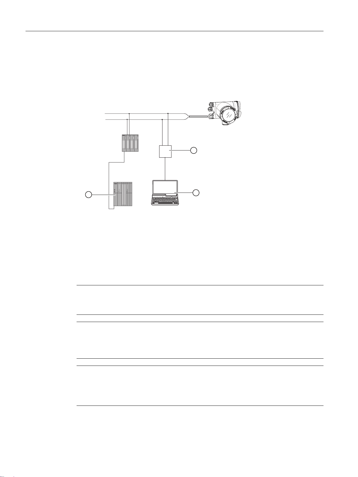
2.2 Connecting the Current HART, CH1
Communication is via the HART protocol, using:
● HART Communicator (load 230 to 500 Ω)
● PC with HART modem, on which appropriate software is installed, for example
SIMATIC PDM (load 230 to 500 Ω)
● Control system which can communicate via the HART protocol, for example SIMATIC PCS7
① SIMATIC PLC system with HART interface
② HART modem
③ PC with SIMATIC PDM or similar application
Figure 2-2 Possible system configurations
2.2 Connecting the Current HART, CH1
Note
4 to 20 mA output
It is not required to use shielded cables for the pure 4 to 20 mA current output.
Note
HART communication
It is recommended by the FieldComm Group (FCG) to use shielded cables for the HART
communication.
Note
Passive channels only
Channel 1 power supply must be separated from that for channels 2 to 4.
Signal return (or common) can be joined.
FCT030 HART (From firmware 4.0)
10 Function Manual, 06/2018, A5E39931617-AB
Page 11
5
4
5
6
,VLJQDO
U
0
)&
Ca+
Cp-
C
8
LQW
+
-
,VLJQDO
8
H[W
8
Ca+
+
-
Cp-
)&
C
HART Communication Interface
2.2 Connecting the Current HART, CH1
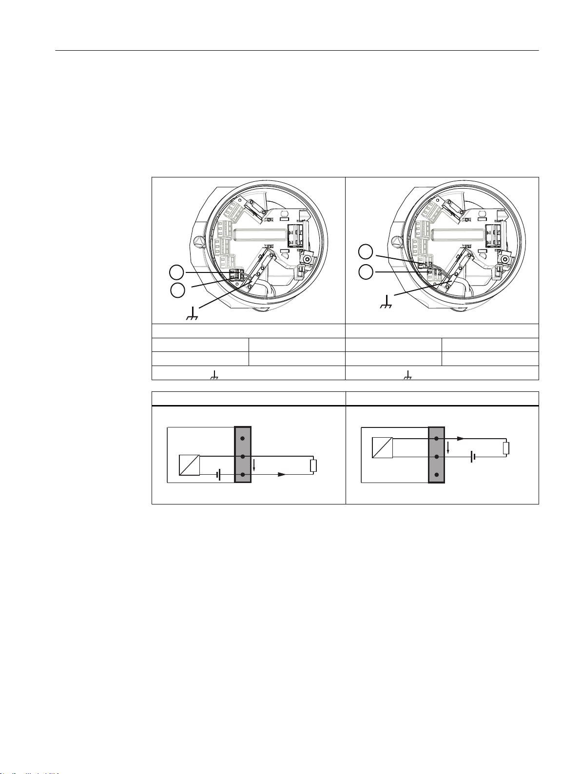
1. Remove cap and ferrule from cable gland and slide onto cable.
2. Push cable through open gland and cable path.
3. Restore ferrule and tighten cap to lightly hold cable in place.
4. Signal cable screen is folded back over outer sheath and grounded beneath cable clamp.
5. Connect wires to terminals using wiring tool, field mount transmitter
Active current output Passive current output
⑤ C ⑥ Cp-
④ Ca+ ⑤ C
Functional Earth Functional Earth
Active current output Passive current output
FCT030 HART (From firmware 4.0)
Function Manual, 06/2018, A5E39931617-AB 11
Page 12
)
)
HART Communication Interface
2.2 Connecting the Current HART, CH1
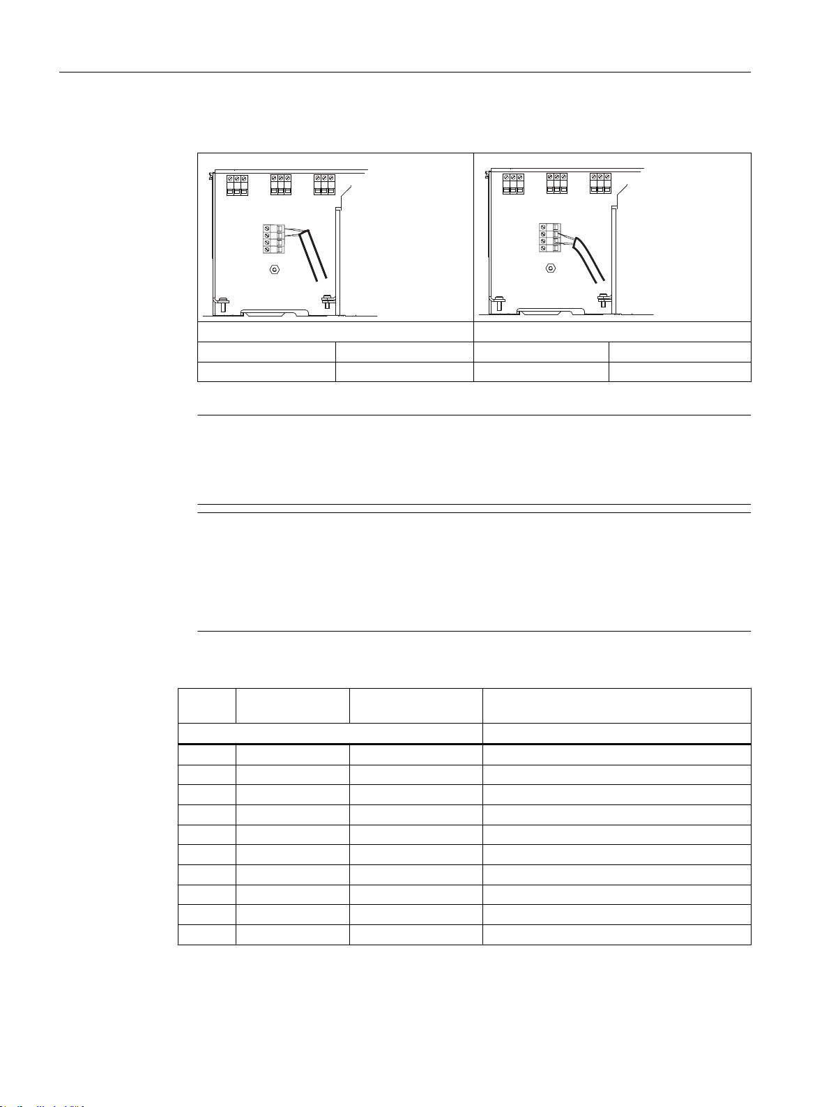
6. Connect wires to terminals, wall mount transmitter.
Active current output Passive current output
5 Ca+ 6 Cp4 C 5 C
7. Tighten cable gland.
Note
For Ex versions active or passive current output is preselected at ordering and cannot be
changed.
Non-Ex versions can be connected as either active or passive.
Note
Load
Signal output: < 500 Ω at 14 to 24 VDC (active), 14 to 30 VDC (passive)
Relay output: 30 VAC/VDC, 100 mA
Passive signal input: 15 to 30 VDC, 2 to 15 mA
Table 2-3 HW polling address
Load [Ω] Voltage (active
Ex) [V]
Measurered
100 3 3 17.7
200 5.9 5.9 19.6
500 11.4 14.9 21.0
1000 14.8 19.2 21.6
2000 17.4 20.1 21.9
5000 19.4 20.4 22.2
10000 20.3 21 22.3
20000 20 20.4 22.4
50000 20.4 20.6 22.5
100000 20.6 20.7 22.6
Voltage (active non
Ex) [V]
24 V DC Voltage supply (passive) [V] Ex and
Non Ex
FCT030 HART (From firmware 4.0)
12 Function Manual, 06/2018, A5E39931617-AB
Page 13

Commissioning
3.1 General requirements
Before commissioning it must be checked that:
● The device has been installed and connected in accordance with the guidelines provided
in the Operating Instruction for FCT030 transmitter
3.2 Operating via SIMATIC PDM
SIMATIC PDM is a software package used to commission and maintain process devices.
See also
www.siemens.com/simatic-pdm. (www.siemens.com/simatic-pdm.)
3
3.3 Functions in SIMATIC PDM
SIMATIC PDM monitors the process values, alarms and status signals of the device. It allows
you to display, compare, adjust, verify, and simulate process device data; also to set schedules
for calibration and maintenance.
3.4 Commissioning steps
In the following it is described how to commission the device with SIMATIC PDM.
The steps are divided into the following sections:
1. Initial Setup (Page 14)
2. Adding device to communication network (Page 15)
3. Wizard - Quick Start via PDM (Page 18)
4. Wizard - Zero Point adjustment (Page 27)
5. Configuring a new device (Page 18)
6. I/O configuration
7. Summary
FCT030 HART (From firmware 4.0)
Function Manual, 06/2018, A5E39931617-AB 13
Page 14
Commissioning
3.5 Initial Setup
3.5 Initial Setup
To ensure that SIMATIC PDM connects properly, please complete the two processes outlined
below:
1. Deactivating buffers
2. Updating the Electronic Device Description (EDD)
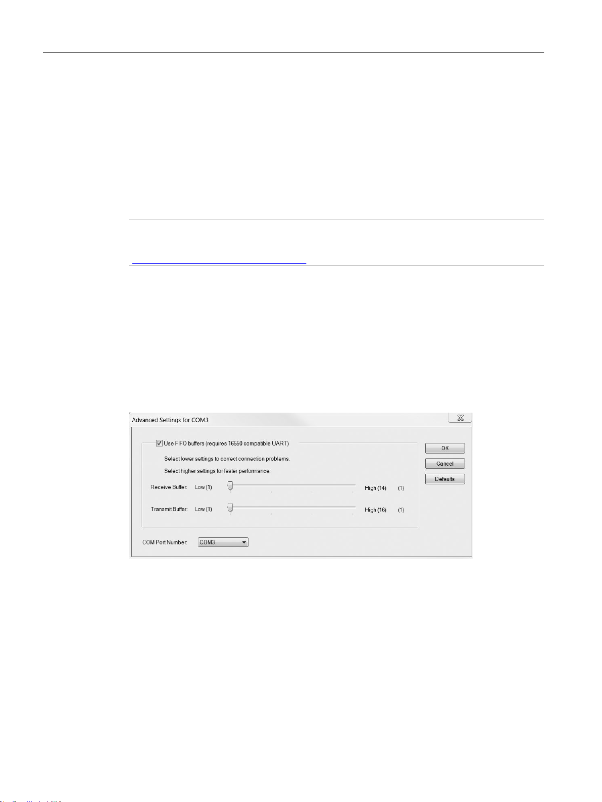
Deactivating buffers for RS 485 COM port
This deactivation is required to align SIMATIC PDM for Windows® operating systems.
Note
Support for Windows operating systems can be found here: support.automation.siemens.com
(http://support.automation.siemens.com)
1. Click Start → Control Panel to begin configuration.
2. Click on Hardware and Sound and then on Device Manager.
3. Open Ports folder and double-click the COM Port used by the system to open the
Communications Port Properties window.
4. Select the Port Settings tab and click the Advanced button.
5. If the Use FIFO buffers check box is deselected, click to select.
6. Set Receiver Buffer and Transmitter Buffer to Low (1).
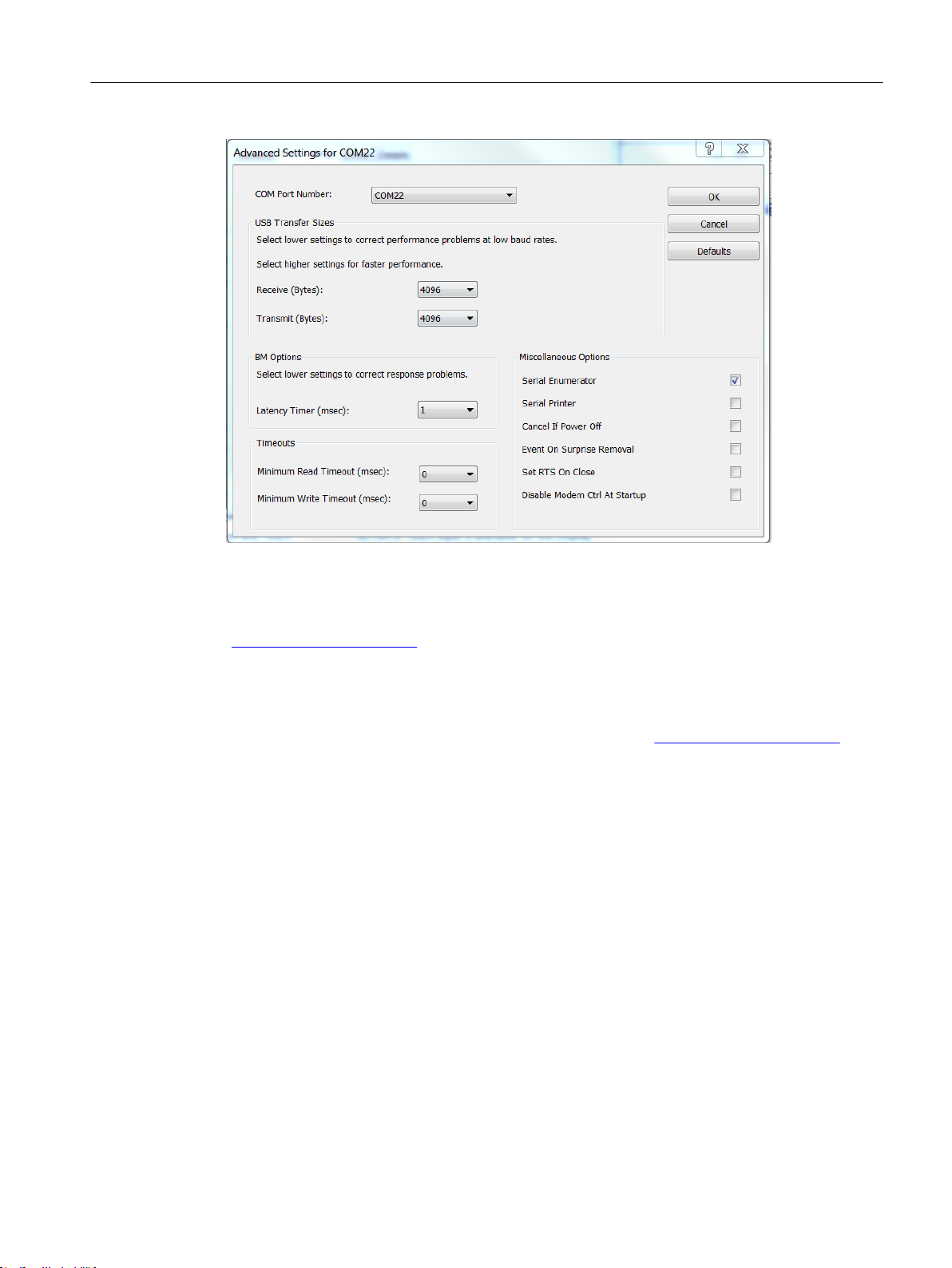
Figure 3-1 COM Port Setting
For serial adapters it can be required to change the Latency Timer (msec) to 1
FCT030 HART (From firmware 4.0)
14 Function Manual, 06/2018, A5E39931617-AB
Page 15
Commissioning
3.6 Adding device to communication network
See also
Updating the Electronic Device Description (EDD)
You can locate the EDD in the SIMATIC PDM Device Library under Devices → HART → Sensors
→ Flow → Coriolis → Siemens AG → SITRANS FC430. Check the product page of our website
(www.siemens.com/FC430) under Support > Software downloads, to make sure you have the
latest version of SIMATIC PDM, the most recent Service Pack (SP) and the most recent hot
fix (HF).
Installing a new EDD:
1. Download the EDD from the product page of our website (www.siemens.com/FC430) and
save the files to your computer.
2. Launch the SIMATIC PDM Device Integration Manager, browse to the EDD file and select
it.
3. Select the check boxes for the devices whose device descriptions are to be integrated. The
check box is automatically selected for devices that have not been integrated or have been
integrated with an older version. You can work with a split device list window.
4. Select Catalog → Integration. The device descriptions are transferred to the PC.
Commissioning steps (Page 13)
Wizard - Quick Start via PDM (Page 18)
3.6 Adding device to communication network
Before setting the parameters, it is necessary to configure the FC430 project in PDM.
FCT030 HART (From firmware 4.0)
Function Manual, 06/2018, A5E39931617-AB 15
Page 16
Commissioning
3.6 Adding device to communication network
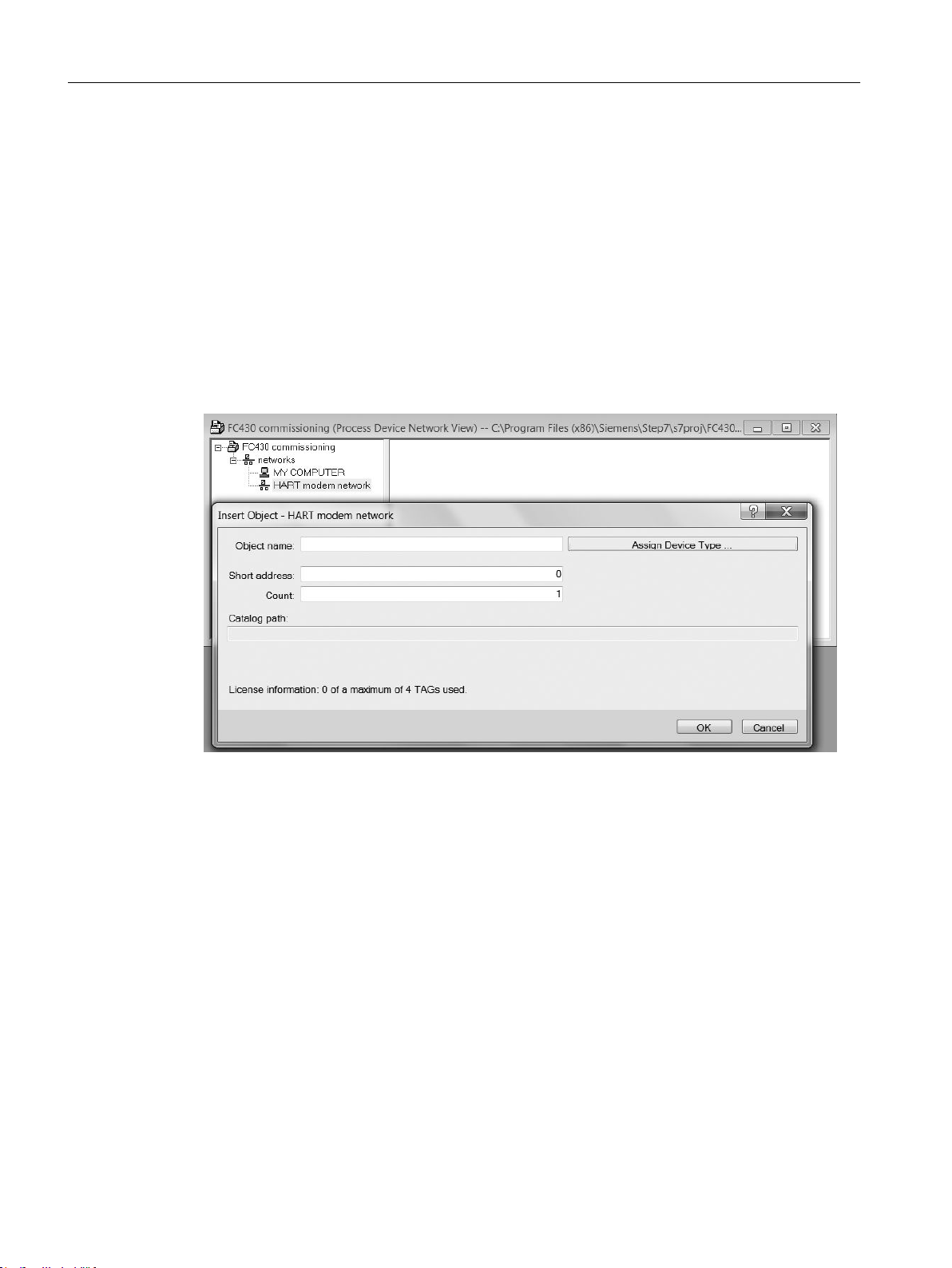
1. Add the device to SIMATIC HART network:
– Select File → New. Type in a project name, for example FC430 commissioning.
– Go to View and select Process Device Network view.
– Right-click on the typed in Project name and select Insert New Object → Networks.
– Right-click on Networks and Insert New Object → Communication Network.
– Click on Assign Device Type and select HART Modem Network. Click OK two times. Your
PC is now added to the HART Modem Network.
– Right-click on HART Modem Network and select Insert New Object → Object.
– Click on Assign Device Type, and select Devices → HART → Sensors → Flow → Coriolis →
SIEMENS AG → SITRANS FC430 Click OK two times.
Figure 3-2 Assigning a HART modem network
2. Set up the communication parameters for SIMATIC HART modem network:
– Select Networks → My computer, right-click on COM Port Interface and select Object
Properties.
– Select the Communication tab and configure the communication parameters.
FCT030 HART (From firmware 4.0)
16 Function Manual, 06/2018, A5E39931617-AB
Page 17
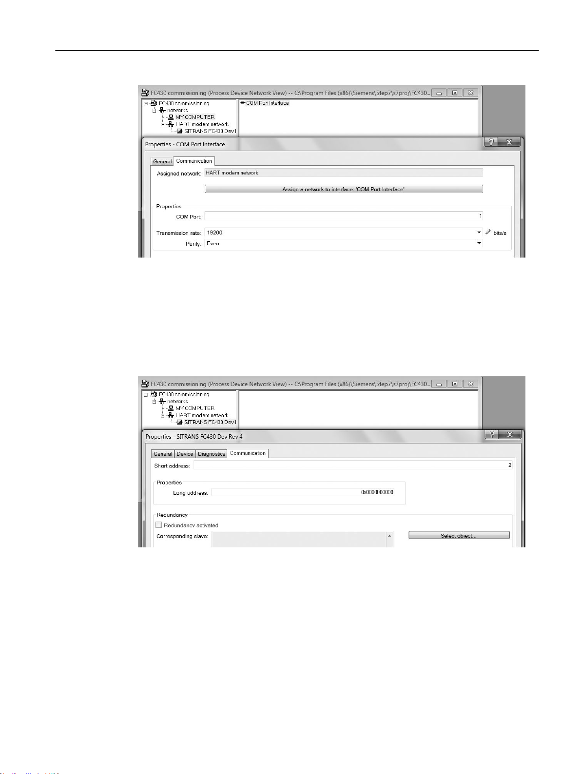
Figure 3-3 HART modem properties
– Click OK.
3. Set up the HART address:
– Select HART modem network.
Commissioning
3.6 Adding device to communication network
– Right-click on the object name SITRANS FC430 and select Object Properties.
– Select the Communication tab and configure the HART address.
Figure 3-4 Set the HART address
– Click OK.
FCT030 HART (From firmware 4.0)
Function Manual, 06/2018, A5E39931617-AB 17
Page 18

Commissioning
3.8 Wizard - Quick Start via PDM
3.7 Configuring a new device
Note
Clicking on "Cancel" during an upload from device to SIMATIC PDM will result in some
parameters NOT being updated.
1. Check that you have the most recent EDD, and if necessary update it, see "Updating the
Electronic Device Description (EDD)" in Initial Setup (Page 14).
2. Launch SIMATIC Manager.
3. Right-click on SITRANS FC430 and select Open Object to open SIMATIC PDM.
4. Click on the device and select Upload to the PG/PC to upload the configuration from he
device.
3.8 Wizard - Quick Start via PDM
The graphic Quick Start Wizard provides an easy 7-step procedure that configures the device
for a simple application.
Please consult the SIMATIC PDM operating instructions or online help for details on using
SIMATIC PDM.
Access level control
Some parameters are protected against changes by access level control. To gain access,
select Access Management from the device menu, select User or Expert mode and enter the
PIN code.
● User
Allows configuration and service of all parameters except calibration parameters. Default PIN
code is 2457.
● Expert
Allows configuration and service of all parameters including flow and density adjustment
parameters. Default PIN code is 2834.
Quick start
Note
● The Quick Start wizard settings are inter-related and changes apply only after you click on
● Do not use the Quick Start Wizard to modify individual parameters.
● Click on "Back" to return and revise settings or "Cancel" to exit the Quick Start.
"Apply" at the wizard to transfer settings to save settings offline and transfer them to the
device.
FCT030 HART (From firmware 4.0)
18 Function Manual, 06/2018, A5E39931617-AB
Page 19

Commissioning
3.8 Wizard - Quick Start via PDM
Launch SIMATIC PDM, open the menu "Device – Wizard - Quick Start", and follow steps.
Figure 3-5 Wizard Quick Start
Step 1 - Identification
Note
The layout of the dialog boxes shown may vary according to the resolution setting for your
computer monitor. The recommended resolution is 1280 x 960.
1. The parameter settings are read from device automatically so the Quick Start wizard starts
with the values stored in device.
FCT030 HART (From firmware 4.0)
Function Manual, 06/2018, A5E39931617-AB 19
Page 20
Commissioning
3.8 Wizard - Quick Start via PDM
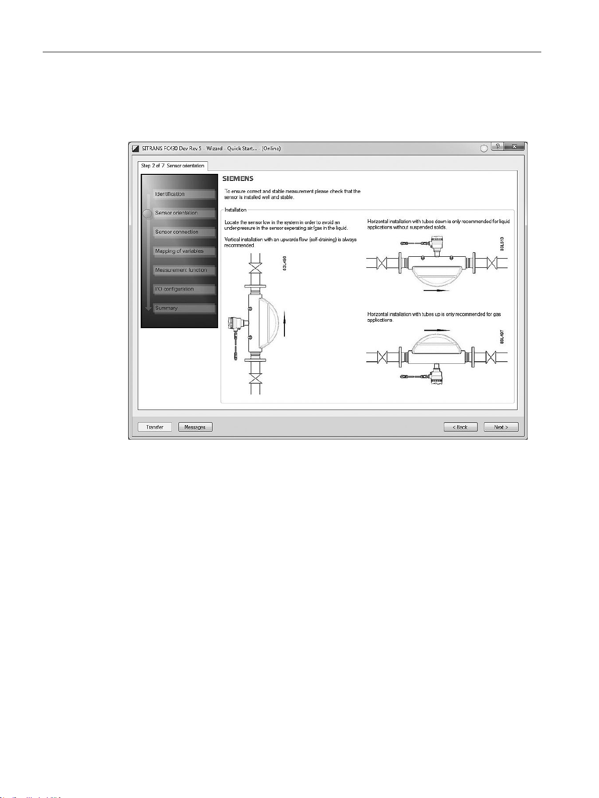
Step 2 - Sensor orientation
Step 2 shows an overview of the various recommended installation orientations depending on
the application.
Figure 3-6 Quick start step 2
FCT030 HART (From firmware 4.0)
20 Function Manual, 06/2018, A5E39931617-AB
Page 21

Step 3 - Sensor connection (remote version only)
Step 3 shows connection of compact and remote systems.
Commissioning
3.8 Wizard - Quick Start via PDM
Figure 3-7 Quick start step 3
FCT030 HART (From firmware 4.0)
Function Manual, 06/2018, A5E39931617-AB 21
Page 22

Commissioning
3.8 Wizard - Quick Start via PDM
Step 4 - Mapping of variables
Set the process values (PV, SV, TV, and QV) to be used in the HART system integration and
click on "Next".
Figure 3-8 Quick start step 4
FCT030 HART (From firmware 4.0)
22 Function Manual, 06/2018, A5E39931617-AB
Page 23

Step 5 - Measurement conditions
Configure the measurement conditions for the selected process variables. Change "Flow
Direction" if necessary.
Commissioning
3.8 Wizard - Quick Start via PDM
Figure 3-9 Quick start step 5
FCT030 HART (From firmware 4.0)
Function Manual, 06/2018, A5E39931617-AB 23
Page 24

Commissioning
3.8 Wizard - Quick Start via PDM
Figure 3-10 Filter setting selection
FCT030 HART (From firmware 4.0)
24 Function Manual, 06/2018, A5E39931617-AB
Page 25

Step 6 - I/O configuration
Configure the current output (channel 1). The process value is selected as PV in step 4
"Mapping of variables".
Commissioning
3.8 Wizard - Quick Start via PDM
Figure 3-11 Quick start step 6
FCT030 HART (From firmware 4.0)
Function Manual, 06/2018, A5E39931617-AB 25
Page 26

Commissioning
3.8 Wizard - Quick Start via PDM
Step 7 - Summary
Check parameter setting in Summary and apply to transfer the settings to the device.
Figure 3-12 Quick start step 7
The settings have been transferred to the device successfully.
FCT030 HART (From firmware 4.0)
26 Function Manual, 06/2018, A5E39931617-AB
Page 27

3.9 Wizard - Zero Point adjustment
Open the menu Device – Wizard - Zero Point Adjustment.
Figure 3-13 Wizard - Zero point adjustment
Select "Auto". Click on "Next".
Commissioning
3.9 Wizard - Zero Point adjustment
Figure 3-14 Zero point adjustment step 1
It is recommended to use the default settings. Change the "Zero Point Adjustments Settings",
if necessary.
Click on "Perform".
FCT030 HART (From firmware 4.0)
Function Manual, 06/2018, A5E39931617-AB 27
Page 28

Commissioning
3.10 Changing parameter settings using SIMATIC PDM
Figure 3-15 Zero point adjustment step 2
3.10 Changing parameter settings using SIMATIC PDM
Note
For a complete list of parameters upload all parameters from the device first.
Clicking on "Cancel" during an upload from device to SIMATIC PDM will result in some
parameters NOT being updated.
FCT030 HART (From firmware 4.0)
28 Function Manual, 06/2018, A5E39931617-AB
Page 29

Commissioning
3.11 Parameters accessed via drop-down menus
Many parameters are accessed via the online menus in PDM, see "Parameters accessed via
drop-down menus" for the others.
1. Launch SIMATIC PDM, connect to the appropriate device and upload data.
2. Adjust parameter values in the parameter value field then click on "Enter". The status fields
read "Changed".
3. Open the "Device" menu, click on "Download to device", then use "File – Save" to save
settings offline. The status fields are cleared.
Figure 3-16 Changing parameter settings using SIMATIC PDM
3.11 Parameters accessed via drop-down menus
Click on "Device" or "View" to open the associated drop-down menus.
FCT030 HART (From firmware 4.0)
Function Manual, 06/2018, A5E39931617-AB 29
Page 30

Commissioning
3.11 Parameters accessed via drop-down menus
Device drop-down menus
Figure 3-17 Device drop-down menus
Menu Description
Download to Device Downloads all writable parameters to the device
Upload to PC/PG Uploads all parameters from the device to the parameter
table
Assign address and TAG Assign communication address and TAG name
Value comparison Compare values between device / project
Object properties Properties for device and project
Calibration log Create calibration logs for field devices.
Cange log The change log records which actions have been per‐
formed with SIMATIC PDM on devices
Set the device checked The device can be set to checked / or unchecked
Check configuration Check configuration if it contains errors
Wizard - Quick Start Guide for a quick commissioning
Wizard - Zero Point Adjustment Guide for zero point adjustment (automatic and manual)
D/A Trim Calibration of current output (channel 1)
FCT030 HART (From firmware 4.0)
30 Function Manual, 06/2018, A5E39931617-AB
Page 31

Commissioning
3.11 Parameters accessed via drop-down menus
Menu Description
Totalizer Controlling totalizers 1, 2 and 3
Maintenance Setup of maintenance functions
Enable Alarms Enables individual alarms
Audit Trail Lists parameter changes, FW updates, and alarm history
logs
Simulation Simulation of process values, alarms, and inputs/outputs
(channels 2 to 4)
Loop Test Simulation of current output (channel 1)
Security Possibility to upgrade access level from “restricted” to
“user” or “expert” and to change PIN code for “user” and
"expert" level
Reset Restore order configuration
Device restart
Configuration Flag Reset Commands reset the configuration flag
HART Communication Number of preambles
Trim signal inputs/outputs Calibration of current output (channels 2 to 4)
Dosing Controlling and calibration of dosing
Firmware update This function allows the user to install firmware that has
been placed on the SDcard
FCT030 HART (From firmware 4.0)
Function Manual, 06/2018, A5E39931617-AB 31
Page 32

Commissioning
3.11 Parameters accessed via drop-down menus
FCT030 HART (From firmware 4.0)
32 Function Manual, 06/2018, A5E39931617-AB
Page 33

HART commands
4.1 Device Variables
All four dynamic variables PV, SV, TV and QV are supported. Except for PV, they can all be
freely mapped to all dynamic device variables. The following table shows the possible
mappings.
Default values:
PV = Mass flow
SV = Volume flow
TV = Density
QV = Media temperature
Table 4-1 Device Variables
4
Device Varia‐
ble Number
0 Mass flow X X X X
1 Volume flow X X X X
2 Density X X X X
3 Fluid Temperature X X X X
4 Standard Volume Flow X X X X
5 Fractional Flow A X X X X
6 Fractional Flow B X X X X
7 Fractional Percentage Flow A X X X X
8 Fractional Percentage Flow B X X X X
9 Reference Density X X X X
10 Electronics Temperature TRN X X X X
11 Totalized Value 1 X X X
12 Totalized Value 2 X X X
13 Totalized Value 3 X X X
14 Frame Temperature X X X X
15 Totalized batch amount X X X
Device Variable Name PV SV TV QV
FCT030 HART (From firmware 4.0)
Function Manual, 06/2018, A5E39931617-AB 33
Page 34

HART commands
4.2 Universal commands
4.2 Universal commands
The device supports the following universal commands:
Table 4-2 Universal commands
Com‐
mand
num‐
ber
0 Read Unique Identifier 254, device_type, request_pream‐
1 Read Primary Variable PV.DEVICE_VARIABLE.DIGI‐
2 Read Loop Current And Percent Of Range PV.DAQ.ANALOG_VALUE,
3 Read Dynamic Variables And Loop Current PV.DAQ.ANALOG_VALUE,
6 Write Polling Address polling_address, loop_cur‐
7 Read loop configuration polling_address, loop_cur‐
8 Read Dynamic Variable Classification PV.DEVICE_VARIABLE.CLASSI‐
9 Read Device Variable With Status Read
Function Parameters
bles, universal_revision, transmit‐
ter_revision, software_revision,
hardware_revision <0xf8>, physi‐
cal_signaling_code <0x07>, de‐
vice_flags, device_id, re‐
sponse_preambles,
max_num_device_variables, con‐
fig_change_counter, exten‐
ded_fld_device_status, manufac‐
turer_id, private_label_distributor,
device_profile
TAL_UNITS, PV.DEVICE_VARI‐
ABLE.DIGITAL_VALUE
PV.RANGING.PER‐
CENT_RANGE
PV.DEVICE_VARIABLE.DIGI‐
TAL_UNITS,
SV.DEVICE_VARIABLE.DIGI‐
TAL_UNITS, SV.DEVICE_VARI‐
ABLE.DIGITAL_VALUE, TV.DE‐
VICE_VARIABLE.DIGI‐
TAL_UNITS, TV.DEVICE_VARIA‐
BLE.DIGITAL_VALUE, QV.DE‐
VICE_VARIABLE.DIGI‐
TAL_UNITS, QV.DEVICE_VARI‐
ABLE.DIGITAL_VALUE
rent_mode
rent_mode
FICATION, SV.DEVICE_VARIA‐
BLE.CLASSIFICATION, TV.DE‐
VICE_VARIABLE.CLASSIFICA‐
TION, QV.DEVICE_VARIA‐
BLE.CLASSIFICATION
Read /
Write /
Command
Read
Read
Read
Read
Write
Read
Read
FCT030 HART (From firmware 4.0)
34 Function Manual, 06/2018, A5E39931617-AB
Page 35

HART commands
4.2 Universal commands
Com‐
mand
num‐
ber
11 Read Unique Identifier Associated With Tag 254, device_type, request_pream‐
12 Read Message message
13 Read Tag, Descriptor, Date tag, descriptor, date
14 Read Primary Variable Transducer Informa‐
15 Read Device Information PV.DAQ.ALARM_CODE,
16 Read Final Assembly Number final_assembly_number
17 Write Message message Write
18 Write Tag, Descriptor, Date tag, descriptor, date
19 Write Final Assembly Number final_assembly_number
20 Read Long Tag longTag Read
Function Parameters
bles, universal_revision, transmit‐
ter_revision, software_revision,
hardware_revision <0xf8>, physi‐
cal_signaling_code <0x07>, de‐
vice_flags, device_id, re‐
sponse_preambles,
max_num_device_variables, con‐
fig_change_counter, exten‐
ded_fld_device_status, manufac‐
turer_id, private_label_distributor,
device_profile
PV.DEVICE_VARIABLE.SEN‐
tion
SOR_SERIAL_NUMBER, PV.DE‐
VICE_VARIABLE.DIGI‐
TAL_UNITS, PV.DEVICE_VARI‐
ABLE.UPPER_SENSOR_LIMIT,
PV.DEVICE_VARIABLE.LOW‐
ER_SENSOR_LIMIT, PV.DE‐
VICE_VARIABLE.MINI‐
MUM_SPAN
PV.RANGING.TRANS‐
FER_FUNCTION, PV.RANG‐
ING.RANGE_UNITS, PV.RANG‐
ING.UPPER_RANGE_VALUE,
PV.RANGING.LOW‐
ER_RANGE_VALUE, PV.DE‐
VICE_VARIABLE.DAMP‐
ING_VALUE, write_protect, 250,
PV.DAQ.ANALOG_CHAN‐
NEL_FLAGS
Read /
Write /
Command
Read
Read
Write
Write
FCT030 HART (From firmware 4.0)
Function Manual, 06/2018, A5E39931617-AB 35
Page 36

HART commands
4.3 Common practice commands
Com‐
mand
num‐
ber
21 Read Unique Identifier Associated With
22 Write Long Tag longTag Write
38 Reset Configuration Changed Flag Command
48 Read Additional Device Status device_specific_status_0, de‐
Function Parameters
254, device_type, request_pream‐
Long Tag
bles, universal_revision, transmit‐
ter_revision, software_revision,
hardware_revision <0xf8>, physi‐
cal_signaling_code <0x07>, de‐
vice_flags, device_id, re‐
sponse_preambles,
max_num_device_variables, con‐
fig_change_counter, exten‐
ded_fld_device_status, manufac‐
turer_id, private_label_distributor,
device_profile
vice_specific_status_1, de‐
vice_specific_status_2, de‐
vice_specific_status_3, de‐
vice_specific_status_4, de‐
vice_specific_status_5,
extended_fld_device_status,
0x00
Read /
Write /
Command
Read
Read
Note
Command #15: Read Device Information / Write Protect Code
The device does not support Write Protection. Therefore the response to command #15
contains the Write Protect Code 251 (as specified in the HART specification).
4.3 Common practice commands
The device supports the following common practice commands:
Table 4-3 Common practice commands
Command number Function
33 Read Device Variables
34 Write Primary Variable Damping Value
35 Write Primary Variable Range Values
36 Set Primary Variable Upper Range Value
37 Set Primary Variable Lower Range Value
40 Enter/Exit Fixed Current Mode
42 Perform Device Reset
44 Write Primary Variable Units
FCT030 HART (From firmware 4.0)
36 Function Manual, 06/2018, A5E39931617-AB
Page 37

Command number Function
45 Trim Loop Current Zero
46 Trim Loop Current Gain
50 Read Dynamic Variable Assignments
51 Write Dynamic Variable Assignments
53 Write Device Variables Units
54 Read Device Variables Information
59 Write Number Of Response Preambles
60 Read Analog Channel And Percent Of Range
63 Read Analog Channel Information
70 Read Analog Channel Endpoint Values
95 Read Device Communications Statistics
4.4 Burst Mode
This device does not support Burst-Mode.
HART commands
4.5 Device-specific commands
4.4.1 Catch Device Variable
This device does not support Catch Device Variable.
4.5 Device-specific commands
4.5.1 Command #130: Read. User Login
Operation: READ
The access level of the HART fieldbus interface can be changed with this command.
By writing a wrong PIN or by timeout the HART-Access-Level falls back to the default access
level.
The HART Access-Level is falling back to RUP after 10 minutes. Timeout is restarted with
every Write-Access over HART.
Byte Format Description
None
FCT030 HART (From firmware 4.0)
Function Manual, 06/2018, A5E39931617-AB 37
Page 38

HART commands
4.5 Device-specific commands
Byte Format Description
0...1
2
Code Class Description Explanation
0 Success No Command-Specific Errors
5 Error Too few Data Bytes Received Not enough data for User PIN
6 Error Device Specific Command Error
Quintessence
The device supports the following device-specific commands:
Unsigned-16
Enrum
Written User PIN
Resulting Access-Level
16 (RUP)
32 (EUP)
64 (SUP)
Command
number
130 User Login
131 Read Current HART Access Level
140 Read Parameter(s)
141 Write Parameter(s)
142 Read Unit Related Parameter(s)
143 Write Unit Related Parameter(s)
144 Read Device Variable Information
145 Read Unit Related Parameter(s)
146 Write Unit Related Parameter(s)
Description
4.5.2 Command #131: Read, Current HART Access Level
Operation: READ
This command reads the currently set HART Access Level from the device.
Byte Format Description
None
Byte Format Description
0 Enum Current Access Level
16 (RUP)
32 (EUP)
64 (SUP)
FCT030 HART (From firmware 4.0)
38 Function Manual, 06/2018, A5E39931617-AB
Page 39

Code Class Description Explanation
0 Success No Command-Specific Errors
6 Error Device Specific Command Error
4.5.3 Command # 140: Read Parameter(s)
Operation: READ
This command is a general read access command, used to read one or more parameters from
the device. The parameters to read are specified by MODBUS registers that are provided in
the request data.
The value returned when reading a parameter is in its base unit e.g. m³/s, kg/s, kg, m³, °C
(depending on the parameter definition).
For unit related readings of parameters see command #142.
Table 4-4 Request Data Bytes
HART commands
4.5 Device-specific commands
Byte Format Description
0…1 Unsigned-16 MODBUS register of parameter 1
2...3 Unsigned-16 MODBUS register of parameter 2
…
2*n-2…
Unsigned-16 MODBUS register of parameter n
2*n-1
Table 4-5 Response Data Bytes
Byte Format Description
0…? <parameter-specific> Value of parameter 1
<parameter-specific> Value of parameter 2
…
<parameter-specific> Value of parameter n
Code Class Description Explanation
0 Success No Command-Specific Errors
2 Error Invalid Selection Register does not exist
5 Error Too Few Data Bytes Received Not enough data for a Mod‐
bus register
6 Error Device Specific Command Error
16 Error Access Restricted Modbus register is not read‐
able
30 Error Command Response Truncated Response would be too large
FCT030 HART (From firmware 4.0)
Function Manual, 06/2018, A5E39931617-AB 39
Page 40

HART commands
4.5 Device-specific commands
4.5.4 Command # 141: Write Parameter(s)
Operation: WRITE
This command is a general write access command, used to write one or more parameters to
the device. The parameters to write are specified by MODBUS registers that are provided in
the request data.
When writing floating-point values that are related to a unit (e.g. process value limits) the written
value must be related to its base unit e.g. m³/s, kg/s, kg, m³, °C.
For unit related writings of parameters see command #143.
Table 4-6 Request Data Bytes
Byte Format Description
0…1 Unsigned-16 MODBUS register of parameter 1
2…? <parameter-specific> value of parameter 1 to be written
Unsigned-16 MODBUS register of parameter 2
<parameter-specific> value of parameter 2 to be written
…
Unsigned-16 MODBUS register of parameter n
<parameter-specific> value of parameter n to be written
Table 4-7 Response Data Bytes
Byte Format Description
0…1 Unsigned-16 MODBUS register of parameter 1
2…? <parameter-specific> value of parameter 1 as stored
Unsigned-16 MODBUS register of parameter 2
<parameter-specific> value of parameter 2 as stored
…
Unsigned-16 MODBUS register of parameter n
Table 4-8 Command-Specific Response Codes
Code Class Description Explanation
0 Success No Command-Specific Errors
2 Error Invalid Selection Register does not exist
3 Error Parameter too large Value is too large
4 Error Parameter too small Value is too small
5 Error Too Few Data Bytes Received not enough data for a Mod‐
bus register with data
6 Error Device Specific Command Error Invalid value
7 Error Write Protected Device is in write-protect-
mode
FCT030 HART (From firmware 4.0)
40 Function Manual, 06/2018, A5E39931617-AB
Page 41

Code Class Description Explanation
8 Warning Set to Nearest Possible Value Value was adapted
16 Error Access Restricted Modbus register is not write‐
4.5.5 Command # 142: Write Parameter(s)
Operation: READ
This command is a general read access command, used to read one ore more parameters
from the device in a specified unit (only for float-types, has no effect on other parameter types).
The parameters to read are specified by MODBUS registers that are provided in the request
data.
Table 4-9 Request Data Bytes
Byte Format Description
0..1 Unsigned-16 MODBUS register of parameter 1
2 Unsigned-8 Unit Classification to read parameter 1
3 Unsigned-8 Unit Code to read parameter 1
4…5 Unsigned-16 MODBUS register of parameter 2
6 Unsigned-8 Unit Classification to read parameter 2
7 Unsigned-8 Unit Code to read parameter 2
…
4*n-4… 4*n-3 Unsigned-16 MODBUS register of parameter n
4*n-2 Unsigned-8 Unit Classification to read parameter n
4*n-1 Unsigned-8 Unit Code to read parameter n
HART commands
4.5 Device-specific commands
able
Table 4-10 Response Data Bytes
Byte Format Description
0…? <parameter-specific> Value of parameter 1
<parameter-specific>
Value of parameter 2
…
Table 4-11 Command-Specific Response Codes
Code Class Description Explanation
0 Success No Command-Specific Errors
2 Error Invalid Selection
FCT030 HART (From firmware 4.0)
Function Manual, 06/2018, A5E39931617-AB 41
<parameter-specific>
Value of parameter n
● Register does not exist
● Register is not readable
● invalid unit classification/
unit code combination
Page 42

HART commands
4.5 Device-specific commands
Code Class Description Explanation
5 Error Too Few Data Bytes Received Not enough data for a Mod‐
6 Error Device Specific Command Error
30 Error Command Response Truncated Response would be too large
The product ignores the Unit Classification request bytes. They are kept for compatibility
reasons.
The supported unit codes are listed in chapter 11 Supported Engineering Units.
4.5.6 Command # 143: Write Parameter(s)
Operation: WRITE
This command is a general write access command, used to write one or more parameters in
to the device in a specified unit (only for float-types, has no effect on other parameter types).
The parameters to write are specified by MODBUS registers that are provided in the request
data.
bus register
Table 4-12 Request Data Bytes
Byte Format Description
0...1 Unsigned-16 MODBUS register of parameter 1
2 Unsigned-8 Unit Classification to write parameter 1
3 Unsigned-8 Unit Code to write parameter 1
4…x <parameter-specific> value of parameter 1 to be written
Unsigned-16 MODBUS register of parameter 2
Unsigned-8 Unit Classification to write parameter 2
Unsigned-8 Unit Code to write parameter 2
<parameter-specific>
value of parameter 2 to be written
…
Unsigned-16 MODBUS register of parameter n
Unsigned-8 Unit Classification to write parameter n
Unsigned-8 Unit Code to write parameter n
Table 4-13 Response Data Bytes
Byte Format Description
0...1 Unsigned-16 MODBUS register of parameter 1
2 Unsigned-8 Unit Classification of written parameter 1
3 Unsigned-8 Unit Code of written parameter 1
4…x <parameter-specific> value of parameter 1 as stored
<parameter-specific>
value of parameter n to be written
Unsigned-16 MODBUS register of parameter 2
Unsigned-8 Unit Classification of written parameter 2
FCT030 HART (From firmware 4.0)
42 Function Manual, 06/2018, A5E39931617-AB
Page 43

HART commands
4.5 Device-specific commands
Byte Format Description
Unsigned-8 Unit Code of written parameter 2
…
Unsigned-16 MODBUS register of parameter n
Unsigned-8 Unit Classification of written parameter n
Unsigned-8 Unit Code of written parameter n
Table 4-14 Command-Specific Response Codes
Code Class Description Explanation
0 Success No Command-Specific Errors
2 Error Invalid Selection
3 Error Parameter too large provided TRN parameter val‐
4 Error Parameter too small provided TRN parameter val‐
5 Error Too Few Data Bytes Received not enough data for a Mod‐
6 Error Device Specific Command Error Invalid value of SEN param‐
7 Error Write Protected Device is in write-protect-
8 Warning Set to Nearest Possible Value Value was adapted
16 Error Access Restricted Modbus register is not write‐
<parameter-specific>
<parameter-specific>
value of parameter 2 as stored
value of parameter n as stored
● Register does not exist or
● invalid unit classification/
unit code combination
ue is too large
ue is too small
bus register with data
eter
mode
able
The product ignores the Unit Classification request bytes. They are kept for compatibility
reasons.
The supported unit codes are listed in chapter 11 Supported Engineering Units.
The unit code is only evaluated if the specified parameter is an floating-point parameter. If a
unit code unequal to 0 is used for another data type the request is responded with an error.
4.5.7 Command # 144: Read Device Variable Information
Operation: READ
The request is analog to HART Universal Command 9: For each requested PV send one byte
defining the PV of interest, incl. the dynamic variables (see Common Table 34).
FCT030 HART (From firmware 4.0)
Function Manual, 06/2018, A5E39931617-AB 43
Page 44

HART commands
4.5 Device-specific commands
This command can be used to get the required information to use Commands 142+143
properly.
Table 4-15 Request Data Bytes
Byte Format Description
0 Unsigned-8 Device Variable Number for Slot 1
1 Unsigned-8 Device Variable Number for Slot 2
…
n
-1 Unsigned-8 Device Variable Number for Slot n
Table 4-16 Response Data Bytes
Byte Format Description
0…1 Unsigned-16 MODBUS register of process value
2…3 Unsigned-16 MODBUS register of process value unit
4…5 Unsigned-16 MODBUS register of process value status
6 Unsigned-8 Unit Classification
7 Unsigned-8 Unit Code
8…11 Float Process value related to the unit code
12 Unsigned-8 Process value status
13…16 Float Lower process value limit related to the unit code
17…20 Float Upper process value limit related to the unit code
21..41 <See 0…20> Slot 2
...
(n-1)*21
…(n*21)-1
<See 0…20> Slot n
Table 4-17 Command-Specific Response Codes
Code Class Description Explanation
0 Success No Command-Specific Errors
2 Error Invalid Selection Device Variable does not ex‐
ist
5 Error Too Few Data Bytes Received At least one variable must be
requested
6 Error Device Specific Command Error
30 Error Command Response Truncated Response would be too large
FCT030 HART (From firmware 4.0)
44 Function Manual, 06/2018, A5E39931617-AB
Page 45

4.5.8 Command # 145: Read Unit Related Parameter(s)
This command is a general read access command, used to read one or more parameters from
the device. Each unit related parameter has a reference to a unit parameter that is valid for
the HART interface. The currently set unit is used to convert the returned parameter value
(only for float-types, has no effect on other parameter types). The parameters to read are
specified by HART registers that are provided in the request data.
Table 4-18 Request Data Bytes
Byte Format Description
0..1 Unsigned-16 HART register of parameter 1
2…3 Unsigned-16 HART register of parameter 2
…
2*n-2… 2*n-1 Unsigned-16 HART register of parameter n
Table 4-19 Response Data Bytes
Byte Format Description
0…? <parameter-specific> Value of parameter 1
…
<parameter-specific>
<parameter-specific>
Value of parameter 2
Value of parameter n
HART commands
4.5 Device-specific commands
Table 4-20 Command-Specific Response Codes
Code Class Description Explanation
0 Success No Command-Specific Errors
2 Error Invalid Selection Register does not exist
5 Error Too Few Data Bytes Received Not enough data for a HART
register
6 Error Device Specific Command Error
16 Error Access Restricted HART register is not readable
30 Error Command Response Truncated Response would be too large
FCT030 HART (From firmware 4.0)
Function Manual, 06/2018, A5E39931617-AB 45
Page 46

HART commands
4.5 Device-specific commands
4.5.9 Command # 146: Write Unit Related Parameter(s)
This command is a general read access command, used to read one or more parameters from
the device. Each unit related parameter has a reference to a unit parameter that is valid for
the HART interface. The currently set unit is used to convert the returned parameter value
(only for float-types, has no effect on other parameter types). The parameters to read are
specified by HART registers that are provided in the request data.
Table 4-21 Request Data Bytes
Byte Format Description
0...1 Unsigned-16 HART register of parameter 1
2…x <parameter-specific> value of parameter 1 to be written
Unsigned-16 HART register of parameter 2
…
Unsigned-16 HART register of parameter n
<parameter-specific>
<parameter-specific>
value of parameter 2 to be written
value of parameter n to be written
Table 4-22 Response Data Bytes
Byte Format Description
0...1 Unsigned-16 HART register of parameter 1
2…x <parameter-specific> value of parameter 1 as stored
Unsigned-16 HART register of parameter 2
<parameter-specific>
value of parameter 2 as stored
…
Unsigned-16 HART register of parameter n
Table 4-23 Command-Specific Response Codes
Code Class Description Explanation
0 Success No Command-Specific Errors
2 Error Invalid Selection Register does not exist
3 Error Parameter too large provided value is too large
4 Error Parameter too small provided value is too small
5 Error Too Few Data Bytes Received not enough data for a HART
6 Error Device Specific Command Error
7 Error Write Protected Device is in write-protect-
8 Warning Set to Nearest Possible Value Value was adapted
16 Error Access Restricted Parameter is not writeable
<parameter-specific>
value of parameter n as stored
register with data
mode
FCT030 HART (From firmware 4.0)
46 Function Manual, 06/2018, A5E39931617-AB
Page 47

4.6 Supported Engineering Units
The following table lists all engineering units supported by this device.
Table 4-24 Request Data Bytes
Byte Format Description
15 Volumetric Flow cubic feet per minute
16 Volumetric Flow US gallons per minute
17 Volumetric Flow liters per minute
18 Volumetric Flow imperial gallons per minute
19 Volumetric Flow cubic meters per hour
22 Volumetric Flow US gallons per second
23 Volumetric Flow million US gallons per day
24 Volumetric Flow liters per second
25 Volumetric Flow million liters per day
26 Volumetric Flow cubic feet per second
27 Volumetric Flow cubic feet per day
28 Volumetric Flow cubic meters per second
29 Volumetric Flow cubic meters per day
30 Volumetric Flow imperial gallons per hour
31 Volumetric Flow imperial gallons per day
32 Temperature Degrees Celsius
33 Temperature Degrees Fahrenheit
34 Temperature Degrees Rankine
35 Temperature Kelvin
36 Voltage millivolts
38 Frequency Hertz
39 Current milliamperes
40 Volume US gallons
41 Volume liters
42 Volume imperial gallons
43 Volume cubic meters
46 Volume barrels (= 42 US gallons)
51 Time seconds
57 Ratio percent
60 Mass grams
61 Mass kilograms
62 Mass metric tons
63 Mass pounds
64 Mass short tons
65 Mass long tons
70 Mass Flow grams per second
71 Mass Flow grams per minute
HART commands
4.6 Supported Engineering Units
FCT030 HART (From firmware 4.0)
Function Manual, 06/2018, A5E39931617-AB 47
Page 48

HART commands
4.6 Supported Engineering Units
Byte Format Description
72 Mass Flow grams per hour
73 Mass Flow kilograms per second
74 Mass Flow kilograms per minute
75 Mass Flow kilograms per hour
76 Mass Flow kilograms per day
77 Mass Flow metric tons per minute
78 Mass Flow metric tons per hour
79 Mass Flow metric tons per day
80 Mass Flow pounds per second
81 Mass Flow pounds per minute
82 Mass Flow pounds per hour
83 Mass Flow pounds per day
84 Mass Flow short tons per minute
85 Mass Flow short tons per hour
86 Mass Flow short tons per day
87 Mass Flow long tons per hour
88 Mass Flow long tons per day
91 Density grams per cubic centimeter
92 Density kilograms per cubic meter
93 Density pounds per US gallon
94 Density pounds per cubic foot
95 Density grams per milliliter
96 Density kilograms per liter
97 Density grams per liter
98 Density pounds per cubic inch
99 Density short tons per cubic yard
110 Volume bushel
111 Volume cubic yards
112 Volume cubic feet
113 Volume cubic inches
121 Standard Volumetric Flow normal cubic meter per hour
122 Standard Volumetric Flow normal liter per hour
123 Standard Volumetric Flow standard cubic feet per minute
124 Volume liquid barrels (= 31.5 US gallons)
125 Mass ounces
130 Volumetric Flow cubic feet per hour
131 Volumetric Flow cubic meters per minute
132 Volumetric Flow barrels (= 42 US gallons) per second
133 Volumetric Flow barrels (= 42 US gallons) per minute
134 Volumetric Flow barrels (= 42 US gallons) per hour
135 Volumetric Flow barrels (= 42 US gallons) per day
136 Volumetric Flow US gallons per hour
137 Volumetric Flow imperial gallons per second
FCT030 HART (From firmware 4.0)
48 Function Manual, 06/2018, A5E39931617-AB
Page 49

4.6 Supported Engineering Units
Byte Format Description
138 Volumetric Flow liters per hour
146 Density micrograms per liter
147 Density micrograms per cubic meter
166 Standard Volume normal cubic meters
167 Standard Volume normal liters
168 Standard Volume standard cubic feet
170 Density milligrams per liter
Volume beer barrel
Volumetric Flow beer barrel per second
171 Standard Volume standard liter
Volumetric Flow beer barrel per minute
172 Standard Volume standard cubic meter
Volumetric Flow beer barrel per hour
173 Volumetric Flow beer barrel per day
174 Standard Volumetric Flow normal liter per day
175 Standard Volumetric Flow normal liter per minute
176 Standard Volumetric Flow normal liter per second
177 Standard Volumetric Flow standard liter per day
178 Standard Volumetric Flow standard liter per hour
179 Standard Volumetric Flow standard liter per minute
180 Standard Volumetric Flow standard liter per second
181 Standard Volumetric Flow normal cubic meter per day
182 Standard Volumetric Flow normal cubic meter per minute
183 Standard Volumetric Flow normal cubic meter per second
184 Standard Volumetric Flow standard cubic feet per day
185 Standard Volumetric Flow standard cubic feet per hour
186 Standard Volumetric Flow standard cubic feet per second
187 Standard Volumetric Flow standard cubic meter per day
188 Standard Volumetric Flow standard cubic meter per hour
189 Standard Volumetric Flow standard cubic meter per minute
190 Corrected Volumetric Flow standard cubic meter per second
235 Volumetric Flow US gallons per day
236 Volume hectoliters
253 Volume Special (custom unit)
Volumetric Flow Special (custom unit)
Standard Volumetric Flow Special (custom unit)
Mass Special (custom unit)
Mass Flow Special (custom unit)
HART commands
FCT030 HART (From firmware 4.0)
Function Manual, 06/2018, A5E39931617-AB 49
Page 50

HART commands
4.7 HART specific information table
4.7 HART specific information table
In the following table available Modbus device parameters of the SITRANS FCT030 are
described.
Table 4-25 Operating conditions
Modbus
Register
2100 Unsigned / 1Flow
2130 Unsigned / 1Process
Data type
Size [bytes]
Parameter Description Default
Direction
Noise
Damping
Define positive and negative
flow direction.
Default positive flow direction
is indicated by the arrow
on the sensor.
Possible selections:
● 0: Negative:
The flow is measured '+' in
default
negative direction and '-'
in default positive direction.
● 1: Positive:
The flow is measured '+' in
default
positive direction and '-'
in default negative direction
Select process noise
damping level:
0: 55 ms filtering
(Centrifugal Pump)
1: 110 ms filtering
(Triplex Pump)
2: 220 ms filtering
(Duplex Pump)
3: 400 ms filtering
(Simplex Pump)
4: 800 ms filtering
(Cam Pump)
Value
value
1 0 to 1 Read /
2 0 Low to 4
range
High
Access
level
Write
Read /
Write
FCT030 HART (From firmware 4.0)
50 Function Manual, 06/2018, A5E39931617-AB
Page 51

HART commands
4.7 HART specific information table
Modbus
Register
2125 Float / 4 Low Mass‐
2426 Float / 4 Massflow
Table 4-26 Volume flow
Modbus
Register
2170 Float / 4 Low Volu‐
Data type
Size [bytes]
Data type
Size [bytes]
Parameter Description Default
flow CutOff
Correction
Factor
Parameter Description Default
meflow
Cut Off
Set massflow limit for low
flow cut-off.
Below this limit massflow
output is forced to zero.
If Low Flow Cut-Off is set to
0, the cut-off functionality is
disabled.
Notice:
It is recommended to set a
lower value for gas applica‐
tions.
Specify correction factor for
use in the massflow calcula‐
tion
Define the numerical volume‐
flow value below which the
volume flow output is forced
to zero.
Value
value
Sen‐
sor
size
Specif‐
ic
1 -1.999 to
value
Sen‐
sor
size
specif‐
ic
range
0 to 1023 Read /
+1.999
Value
range
0 to 0.177 Read /
Access
level
Write
Read /
Write
Access
level
Write
Table 4-27 Density
Data type
Modbus
Register
2127 Float / 4 Empty
2129 Unsigned / 1Empty
FCT030 HART (From firmware 4.0)
Function Manual, 06/2018, A5E39931617-AB 51
Size [bytes]
Parameter Description Default
value
Tube Limit
Tube
Detection
Define threshold value of
empty tube
Set automatic detection of
Empty Tube On/Off
0 = off (Empty tube is off).
1 = on
(a density value below Empty
Tube Limit triggers an alarm.
All flow rate values are forced
to zero %).
500
[kg/m3]
0 0 to 1
Value
range
-14 000 to
+14 000
Access
level
Read /
Write
Read /
Write
Page 52

HART commands
4.7 HART specific information table
Data type
Modbus
Register
2442 Float / 4 Density
2444 Float / 4 Density
Table 4-28 Totalizers
Modbus
Register
8303 Unsigned / 1TOT1_SET Control totalizer 1 0 0: TOTALIZE
8403 Unsigned / 1TOT2_SET Control totalizer 2 0 0: TOTALIZE
8503 Unsigned / 1TOT3_SET Control totalizer 3 0 0: TOTALIZE
Size [bytes]
Data type
Size [bytes]
Parameter Description Default
value
Set density compensation
Correction
Factor
Correction
Offset
Parameter Description Default
value (gain) in order to make
a density correction (scale
factor).
To increase the displayed
density value with +0.5 %,
set the density factor to 1.005.
The displayed density value
will now be 0.5 % higher than
before
Set density compensation
value (offset) in order to
make an offset on the meas‐
ured density.
1 -1.999 to
0
[kg/m3]
value
Value
range
+1.999
-1 400 to
+1 400
Value
range
1: RESET
2: PRESET
3: HOLD
1: RESET
2: PRESET
3: HOLD
1: RESET
2: PRESET
3: HOLD
Access
level
Read /
Write
Read /
Write
Access
level
Read /
Write
Read /
Write
Read /
Write
Note
After the command Reset or Preset has been send to the device, the command Totalize must
be send, to continue totalizing
FCT030 HART (From firmware 4.0)
52 Function Manual, 06/2018, A5E39931617-AB
Page 53

Table 4-29 Fraction
HART commands
4.7 HART specific information table
Modbus
Register
7869 Unsigned / 1ACTIVE_
Data type
Size [bytes]
Parameter Description Default
FRAC‐
TION
Selection of the currently
used fraction calibration pa‐
rameter set
Value
value
0 0: no fraction
range
Standard
Fractions:
1: American
Petroleum In‐
stitute (API)
number
2: Balling
3: °Baumé
light
4: °Baumé
heavy
5: °Brix
6: °Oechsle
7: °Plato
8: Specific
Gravity
9: °Twaddell
10: % High
Fructose
Corn Syrup
HFCS42
11: % High
Fructose
Corn Syrup
HFCS55
12: % High
Fructose
Corn Syrup
HFCS90
13: EthanolWater 0% to
20%
14: EthanolWater 15% to
35%
15: EthanolWater 30% to
55%
16: EthanolWater 50% to
100%
17...127: re‐
served
Customized
Fraction:
Access
level
Read /
Write
FCT030 HART (From firmware 4.0)
Function Manual, 06/2018, A5E39931617-AB 53
Page 54

HART commands
4.8 Example using HART command
Modbus
Register
Data type
Size [bytes]
Parameter Description Default
4.8 Example using HART command
4.8.1 Reset totalizer 1
Use the HART command 141: Write Parameter(s)
Command #141: Operation: WRITE
Table 4-30 Request Data Bytes
Byte Format Description
0…1 Unsigned-16 Modbus register of parameter 1
2…? <parameter-specific> value of parameter 1 to be written
Unsigned-16 Modbus register of parameter 2
<parameter-specific> value of parameter 2 to be written
…
Unsigned-16 Modbus register of parameter n
<parameter-specific> value of parameter n to be written
value
Value
range
128: custom‐
ized fraction
Access
level
Table 4-31 Response Data Bytes
Byte Format Description
0…1 Unsigned-16 Modbus register of parameter 1
2…? <parameter-specific> value of parameter 1 as stored
Table 4-32 Command-Specific Response Codes
Code Class Description Explanation
0 Success No Command-Specific Errors
2 Error InHartvalid Selection Register does not exist
3 Error Parameter too large provided value is too large
4 Error Parameter too small provided value is too small
Unsigned-16 Modbus register of parameter 2
<parameter-specific> value of parameter 2 as stored
…
Unsigned-16 Modbus register of parameter n
<parameter-specific> value of parameter n as stored
FCT030 HART (From firmware 4.0)
54 Function Manual, 06/2018, A5E39931617-AB
Page 55

HART commands
4.8 Example using HART command
Code Class Description Explanation
5 Error Too Few Data Bytes Received not enough data for a HART-
register with data
6 Error Device Specific Command Error
7 Error Write Protected Device is in write-protect-
mode
8 Warning Set to Nearest Possible Value Value was adapted
16 Error Access Restricted HART-register is not writea‐
ble
Request Data Bytes for Reset totalizer 1
Table 4-33 The HART information for Totalizer 1 is (8303 Dec) / (206F Hex)
Byte Format Description
0…1 Unsigned-16 206F
2…? <parameter-specific> 01
Hereafter the Totalizer must be set to totalize, to continue totalizing
Response Data Bytes for Totalize totalizer 1
Table 4-34 The HART information for Totalizer 1 is (8303 Dec) / (206F Hex)
Byte Format Description
0…1 Unsigned-16 206F
2…? <parameter-specific> 01
FCT030 HART (From firmware 4.0)
Function Manual, 06/2018, A5E39931617-AB 55
Page 56

HART commands
4.8 Example using HART command
FCT030 HART (From firmware 4.0)
56 Function Manual, 06/2018, A5E39931617-AB
Page 57

Specification
This device has the following specifications:
Table 5-1 HART communication
Description Specification More information
Manufacturer ID 42 (2A Hex) Manufacturer ID parameter
Device ID 34 (22 Hex) Device type parameter
HART protocol revision 7.5 HART protocol revision parameter
Device revision 5 Device revision parameter
Number of device variables 16 Number of process values, both
Physical layers supported FSK Frequency Shift Keyed
5
measured and derived
FCT030 HART (From firmware 4.0)
Function Manual, 06/2018, A5E39931617-AB 57
Page 58

Specification
FCT030 HART (From firmware 4.0)
58 Function Manual, 06/2018, A5E39931617-AB
Page 59

Definitions
A
Acyclic Data – data read over the acyclic communication channel, and this data could take
several bus scans to be read. The total amount of time that this process takes is random and
therefore acyclic.
Baud Rate – the speed of the network in bits per second.
Class 1 Master – a type of device on a PROFIBUS network and the traditional master in process
control systems. Refers to a Distributed Control System (DCS) or Programmable Logic
Controller (PLC).
Class 2 Master – a type of device on a PROFIBUS network and the traditional engineering
work station. An example of a class 2 master is SIMATIC PDM.
Cyclic Data – data that is read in every bus scan. It’s the input and output data used for control
and is time sensitive.
Deterministic – the knowledge that something is going to occur with a fixed time period. This
is a requirement of advanced control systems.
EDD – the Electronic Device Description is a collection of text files describing all the acyclic
data in a field device and how to read and write them. EDDs are used by configuration software
such as SIMATIC PDM to configure field instruments.
EDDL – Electronic Device Description Language is the language that EDDs are written in.
EDDL is an international standard defined in IEC 61804-2 and IEC 61804-3.
Ethernet – Ethernet is a type of physical layer defined in the IEEE 802.3 standard used for
communications in a local area network.
FDT – Field Device Tool is standard program interface (software) for configuring field devices.
FDT uses Device Type Managers to program field devices. FDT software is an alternative to
EDD based software such as SIMATIC PDM.
FDI – Field Device Integration is the evolution of FDT and EDD technology. It is for configuration
of field devices and is based on OPC-UA (Object Linking and Embedding for Process Control
– Unified Architecture) and EDD technology.
FF – Foundation Fieldbus is a digital protocol used to configure and troubleshoot field
instruments.
FISCO – Fieldbus Intrinsic Safe Concept. A standard that makes it easy to place FISCO
approved instruments into zone 0 and above environments.
FNICO – Fieldbus Non-Incendive Concept. A similar standard to FISCO. It is makes it easy to
place FISCO approved instruments into zone 2 environments.
Full-duplex – Full-duplex refers to a communication link that is bi-directional allowing for both
devices to talk and listen at the same time.
GSD – General System Data (or Generic Slave Description) is a text file in PROFIBUS and a
XML file in PROFINET defining all the protocol information and cyclic data of a field device. It
is used by the network configuration software to identify the slave and to set up the data
exchanged between the master and the slave during cyclic data exchange. GSD was also
originally the German acronym for Gerätestammdaten.
FCT030 HART (From firmware 4.0)
Function Manual, 06/2018, A5E39931617-AB 59
Page 60

Definitions
Gateway – A gateway is a device that joins two different networks together. For example, to
connect a Modbus device to a PROFIBUS network, a Profibus to Modbus gateway is needed.
HART – Highway Addressable Remote Transducer is an industrial protocol used to configure
and troubleshoot field instruments. It is often considered a transition between the 4–20mA
technology and full digital technology since it uses both.
IEC – International Electrical Congress is an international standards organization committed
to creating and maintaining international and open standards for use in the electrical industries.
I/O-Controller – A type of device on a PROFNET network and the traditional master in process
control systems. Refers to a Distributed Control System (DCS) or Programmable Logic
Controller (PLC).
I/O-Device – A type of device on PROFINET that provides input data or realizes output data
into the real world.
I/O-Supervisor – A type of device on a PROFINET network and the traditional engineering
work station. An example is SIMATIC PDM.
ISA – Instrumentation, Systems, and Automation Society is a world wide organization that
develops standards, certifies industry professionals, provides education and training,
publishes books and technical articles, and hosts conferences and exhibitions.
Interchangeability – The ability to switch from one vendor’s device to another vendor’s similar
device. Interchangeability is a key benefit of PROFIBUS Profile standard.
Intrinsically Safe – An intrinsically safe device keeps the voltage and current low enough so
that it cannot generate a spark of sufficient energy to ignite the gas/particles in the atmosphere
making it safe for use.
Interoperability – The ability to connect different devices from different manufacturers on the
same network and have them work correctly. This is a core strength of PROFIBUS.
Managed Switch – A type of switch that provides additional advanced diagnostics.
Master – A type of device on PROFIBUS that controls communication to slave devices. One
PROFIBUS network can have several Masters on it, and they share communications by using
a token ring protocol.
MBP – Manchester encoded Bus Powered. This is the physical layer defined in IEC-61158-2
that is used for PROFIBUS PA
MBP-IS – This is the same physical layer as MBP, with the addition of power limiters on the
power supply so that the power draws will not exceed those defined for intrinsically safe
operation.
Modem – This is a device that translates a signal from one transmission technology to another.
For example an optical modem converts an electrical signal into light and then back again.
Physical Layer – Refers to medium used to get the ones and zeros from point A to point B.
This layer of the protocol is all about wires and voltage and current levels.
PROFIBUS – Process Fieldbus. Automation communication protocol designed to meet all
industrial and process communication needs.
PROFIBUS DP – DP stands for Decentralized Peripheral and was designed for remote input
output devices. This forms the core protocol of PROFIBUS. If PROFIBUS were a book, it would
be called PROFIBUS DP.
FCT030 HART (From firmware 4.0)
60 Function Manual, 06/2018, A5E39931617-AB
Page 61

Definitions
PROFidrive – A chapter in the PROFIBUS book or PROFINET book that adds functions to the
core protocol for high speed drive applications.
PROFIsafe – A chapter in the PROFIBUS book or PROFINET book that adds functions to the
core protocol for safety applications.
PROFIBUS PA – A chapter in the PROFIBUS book or PROFINET book that adds functions to
the core protocol for process control applications. PA refers to Process Automation.
PROFINET – A second book by the same authors as PROFIBUS. PROFINET is an Ethernet
based protocol that makes use of many sections of the PROFIBUS protocol and make optimal
use of Ethernet.
Profile – A profile is a standardization of a field device from the bus point of view. It defines the
output and the core device parameters.
Protocol – Refers to a set of rules. In industrial communications, it simply refers to a set of
rules defining how something is done. For example, how to get information from point A to
point B. Since one set of rules can be made up of many different sets of rules, one protocol
can be made up of different sub-protocols.
Proxy – A type of gateway defined in PROFINET which, aside from joining two networks
together, also defines how the date is set as well. Think of it as a very easy-to-use gateway.
Slave – A type of device on PROFIBUS that will only talk on the network after a Master device
has requested information.
Switch – A device that directs the traffic on an Ethernet network. It reads the incoming packet
and directs it to the correct port where the target device is located.
TCO – Total Cost of Ownership is a financial term used in asset management referring to all
the costs associated with ownership. In process automation, it is the sum of the cost of the
device plus the cost of commissioning plus the cost of maintaining the device.
Token Ring – A type of protocol using a virtual token that is passed from master to master.
The master can only talk on the bus when it has the token. When it is has finished talking on
the bus, the master passes the token onto another master.
FCT030 HART (From firmware 4.0)
Function Manual, 06/2018, A5E39931617-AB 61
Page 62

Definitions
FCT030 HART (From firmware 4.0)
62 Function Manual, 06/2018, A5E39931617-AB
Page 63

Index
D
Document history, 5
Documentation
Edition, 5
H
HART
Modem, 10
FCT030 HART (From firmware 4.0)
Function Manual, 06/2018, A5E39931617-AB 63
Page 64

Index
FCT030 HART (From firmware 4.0)
64 Function Manual, 06/2018, A5E39931617-AB
 Loading...