

Page 1
Fire Safety & Security Products
Siemens Building Technologies
¼” High Speed Dome Camera CCDA1435-DNX
Quick Installation Guide
5
COM
Alarm1
Alarm2
Alarm3
N.O(Normal Open)
Alarm4
GND
N.C(Normal Close)
Data+
Data-
7
6
9
8
10
D
E
5
11
134
Unit:mm
1
4
3
2
220
164
C
AB
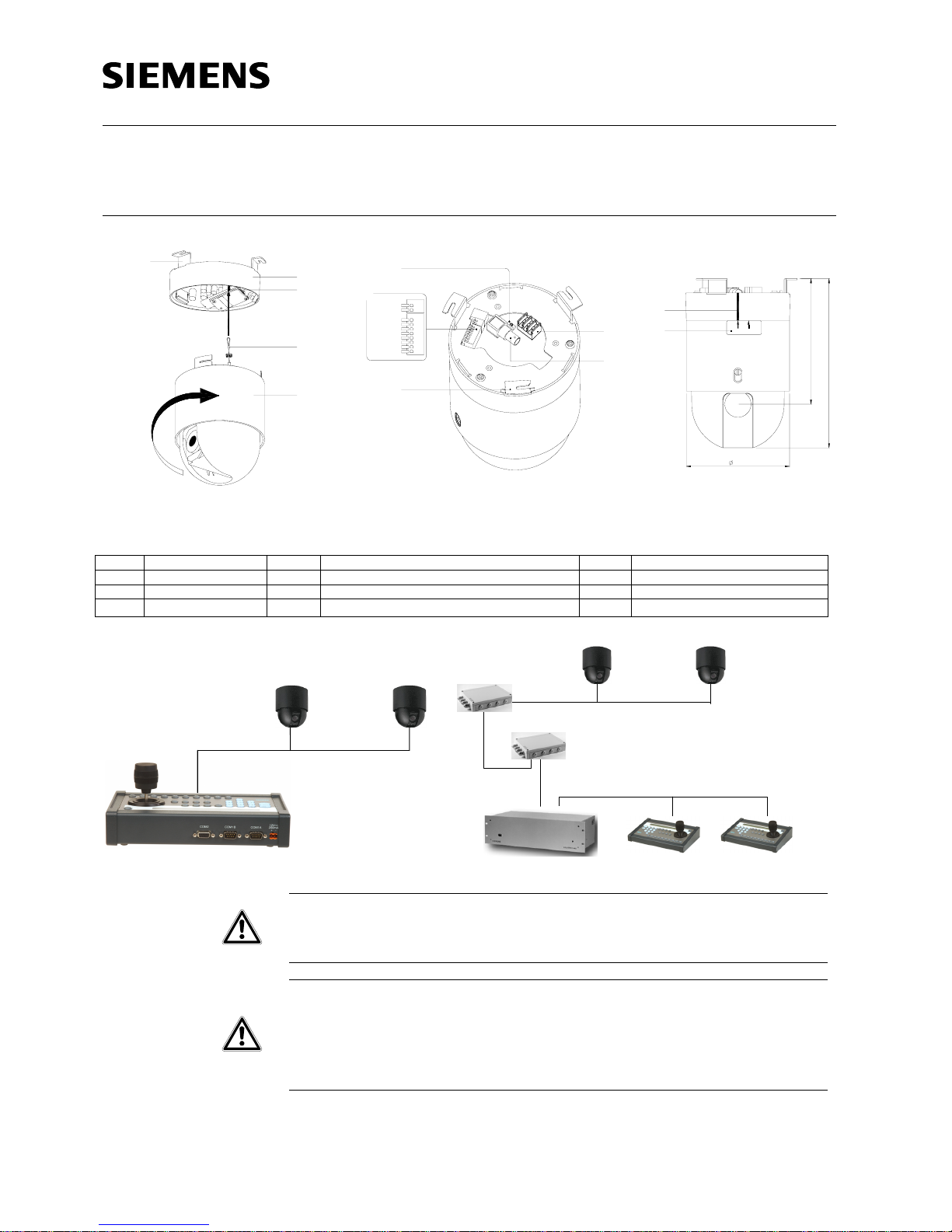
1 Dome base 5 Mounting brackets 9 BNC connector
2 Hook 6 Switch for termination 10 Notch for installation
3 Support wire 7 Terminal for control & Alarm IN/OUT 11 Installation label
4 Dome drive 8 Terminal for power
Control unit CKA482 0
Dome 1 Dome 10
. . .
RS485
TTY
TTY
SIMATRIX 648 Control unit CKA4820 Control unit CKA4820
DomeConverter CAC0103
Dome 1 Dome 10
. . .
RS485
RS485
Interface multiplier
CAD0485-AA
WARNING
1. To reduce the risk of fire or electrical shock, do not expose this product to
rain or moisture.
2. This installation should be made by a qualified service person and should
conform to all local codes.
3. Connect the equipment to 24 VAC UL Listed Class 2 Power Supply.
CAUTION
1. To reduce the risk of electric shock, do not remove cover (or back). No user-
serviceable parts inside.
2. Servicing should only be carried out by qualified service personnel.
3. Ensure that the safety wire (located in the dome base) is engaged.
4. Align notch with "OPEN" arrow and turn dome until notch meets arrow in
"LOCKED" position.
5. Check assembly by pulling on dome. Assembly should not come apart.
6. Only use the supplied EMI core for the power supply.
Page 2

© Siemens Building Technologies AG
Document No.: A24205-A336-B323, Issue: 04.2006 Data subject to change without notice
Package contents
z Dome base
z Dome drive
z 3 mounting screws
z Installation and operating instructions
z EMI-Core
Installation
1. Setup the DIP switch on Dome base
and Dome drive to select baud rate,
address and protocol (see chap. 3.3
in installation manual for details).
2. Refer to Fig. A to install the dome
base and dome drive. Connect the
support wire (3) to the hook (2) of
the dome base (1) carefully to
prevent the dome from dropping.
3. To lock the dome drive (4) to the
dome base, line up the notch (10) to
the right arrow on the label (11) then
turn dome drive to right with both
hands (see figure C) till the notch
lines up to left arrow.
4. Various accessories are available
for indoor or outdoor installation
(see Section 9 in the instruction
manual for installation details).
5. Connect video cable: connect BNC
connector VIDEO OUT (9) to the
monitor with a coax cable.
6. Connect RS485 interface: Connect
RS485 wire from control device to
the Data+/Data- terminal (7).
7. Ensure that only last dome in
RS485-chain is terminated by
setting termination switch (6) to
position on.
8. Connect control signal: 4 alarm IN
and 2 alarm OUT terminals are
available (7)
9. Connect power supply (8): Only 24
V AC ±10% power can be supplied
for this product, voltage over this
range will damage the product.
Connections
One or multiple speed domes can be
controlled via a control panel (see Fig.
D) or a matrix connection (see Fig. E).
Start up procedure
When powered up, the Speed dome will
perform a brief homing routine during
which it checks its function and will then
go its start position. The camera
information including model number,
software version, protocol, address
setting and communication baud rate
are displayed on the screen.
Operation
After power-up, you can use the control
panel to control the pan/tilt and zoom
functions. Some speed dome functions
are operated via preset commands.
Please refer to the table below.
Camera OSD Setup
Press 65 POS to enter the OSD menu.
Most camera settings including pan/tilt
settings, preset settings and others are
configured here. Please refer to the
installation manual for details.
Maintenance
All electrical and electronic
products should be disposed
of separately from the
municipal waste stream via
designated collection
facilities appointed by the
government or the local
authorities.
Technical Data
Part no. 2GF1193-8AD
Description ¼-inch CCD Day Night High Speed Dome
Operating temperature
0 – 50 °C / (32 – 122 °F)
Storage temperature
-20 –+ 60 °C / (-4 –+140 °F)
Weight 1.75 k
g
Power supply
24 V AC ±10% / 50 Hz
Power consumption 20 VA
Interface RS485
Protocol* Siemens, Pelco-D/-P, VCL, Kalatel, Ernitec, Sensomatic, Molynx-D
Data rate 2400, 4800, 9600, 19200 (DIP SW selectable)
* 3rd party protocols may vary without further notice.
English
For more detailed information please refer to the Instruction Manual for ¼" Speed Dome Cameras.
Deutsch
Nähere Informationen hierzu finden Sie im Installationshandbuch für ¼" Speed Dome Kameras.
Français
Veuillez consultez le guide d'opération des cameras ¼" Speed Dome pour d’information plus détaillée.
Nederlands
Uitgebreide Informatie find u in het instruktie handboek voor ¼ Speed Dome Kameras.
Italiano
Per maggiori dettagli si rimanda al manuale specifico di istruzione della telecamera Speed Dome ¼".
Polski
Więcej informacji zawiera instrukcja obsługi zintegrowanej kamery szybkoobrotowej ¼”.
Svenska
För ytterligare information hänvisas till installationsmanualen för ¼" Speed Dome Cameras.
Español
Por favor, para una información más detallada, consulte con el manual de instrucciones de los domos
de alta velocidad de ¼”.
Česky
Pro podrobnější informace se prosím podívejte do návodu pro obsluhu ¼" Speed Dome kamery.
Portugues
Para mais informações, consulte o Manual do utilizador das Câmaras ¼" Speed Dome.
→ <CAMERA SETUP>
<PAN/TILT SETUP>
<PRESET TITLES>
<OTHERS>
EXIT
SIEMENS
(Model)
VERSION***
PROTOCOL***
ADDRESS**
COMM***
 Loading...