

Page 1

Siemens AG
High-Resolution, Day/Night,
Wide-Dynamic, Autofocus
All-In-One Camera with
22x Optical / 16x Digital Zoom
CCAW1417-LPI
Configuration Manual
Page 2

Liefermöglichkeiten und technische Änderungen vorbehalten.
Data and design subject to change without notice. / Supply subject to availability.
© 2011 Copyright by Siemens AG
Wir behalten uns alle Rechte an diesem Dokument und an dem in ihm dargestellten Gegenstand vor. Der Empfänger erkennt diese Rechte
an und wird dieses Dokument nicht ohne unsere vorgängige schriftliche Ermächtigung ganz oder teilweise Dritten zugänglich machen oder
außerhalb des Zweckes verwenden, zu dem es ihm übergeben worden ist.
We reserve all rights in this document and in the subject thereof. By acceptance of the document the recipient acknowledges these rights
and undertakes not to publish the document nor the subject thereof in full or in part, nor to make them available to any third party without our
prior express written authorization, nor to use it for any purpose other than for which it was delivered to him.
Page 3

3
Siemens AG 04.2011
Contents
1 Safety .......................................................................................................5
1.1 Target readers...........................................................................................5
1.2 Work safety information ............................................................................5
1.2.1 Transport...................................................................................................5
1.2.2 Installation .................................................................................................5
1.2.3 Service and maintenance .........................................................................6
1.3 Meaning of the written warning notices ....................................................6
1.4 Meaning of the hazard symbols................................................................6
2 Directives and standards .......................................................................7
3 Technical data .........................................................................................8
4 Details for ordering...............................................................................10
5 Package contents..................................................................................10
6 Description of the camera....................................................................11
6.1 Camera features .....................................................................................11
6.2 Camera parts ..........................................................................................12
7 System installation ...............................................................................13
8 Connection ............................................................................................14
8.1 General ...................................................................................................15
8.1.1 Automatic switching between colour and B/W mode..............................15
8.1.2 RS-485 connection .................................................................................15
8.1.3 Twisted-pair video output........................................................................16
8.1.4 Alarm output............................................................................................16
8.2 Remote configuration..............................................................................17
9 Camera settings ....................................................................................18
9.1 OSD main screen....................................................................................18
9.2 Main menu ..............................................................................................18
9.2.1 FOCUS....................................................................................................18
9.2.2 WB (White Balance)................................................................................19
9.2.3 AE (Auto Exposure) ................................................................................20
9.2.4 BLC / WDR (Back Light Compensation / Wide Dynamic Range)...........20
9.2.5 ALARM / MD (Motion Detection) / FD (Face Detection).........................21
9.2.6 PRIVACY ................................................................................................21
9.2.7 SPECIAL .................................................................................................22
9.2.8 EFFECT ..................................................................................................22
9.2.9 CAMSET .................................................................................................23
10 Troubleshooting and maintenance .....................................................24
10.1 Troubleshooting ......................................................................................24
10.2 Maintenance............................................................................................24
11 Disposal .................................................................................................25
Page 4

Page 5

Safety
5
Siemens AG 04.2011
1 Safety
1.1 Target readers
The instructions in this document are designed only for the following target
readers:
Target readers Qualification Activity Condition of the
equipment
Start-up personnel Has appropriate
technical training with
regard to the tasks
and the products,
devices or systems to
be put in service.
Puts the device or
system which is readily
assembled and installed
on site into service.
New, readily assembled
and installed device or
modified device.
1.2 Work safety information
z Read the general safety precautions before operating the unit.
z Follow all warnings and instructions marked on the device.
z Keep this document available for reference.
z Always pass this document on together with the product.
z Please also take into account any additional country-specific, local safety
standards or regulations concerning project planning, operation and disposal of
the product.
Liability claim
z Do not connect the device if it is damaged or any parts are missing.
z Do not make any changes or modifications to the device that are not mentioned
in this manual and that have not been approved by the manufacturer.
z Use only spare parts and accessories that have been approved by the
manufacturer.
1.2.1 Transport
Damage during transport
z Keep the packaging material for future transportation.
z Do not expose the device to mechanical vibrations or shocks.
1.2.2 Installation
Damage due to unsuitable mounting location
z The environmental conditions recommended by the manufacturer must be
observed.
z Do not operate the device in excessively dusty places.
z Do not expose the device to mechanical vibrations or shocks.
Page 6
Safety
6
Siemens AG 04.2011
Danger of electric shock
z Connect the device only to power sources with the specified voltage. Voltage
supply requirements can be found on the type label and on the mains adapter.
z Connect the device only to a power source that complies with the Limited Power
Source requirements to EN 60950-1.
z Connect the device only to a power source that complies with SELV
requirements.
Risk of cable damage due to stress
z Do not apply tensile stress to the cable.
z Make sure that cables are not under stress, kinked or damaged.
1.2.3 Service and maintenance
Damage to the device
z Do not attempt to service this device yourself. Refer this work to qualified service
personnel.
z Always disconnect the power cable and other cables from the main power
supply before performing maintenance.
z Disconnect the device from the mains supply before cleaning it.
z Do not use liquid cleaners or sprays that contain alcohol, spirit or ammonia.
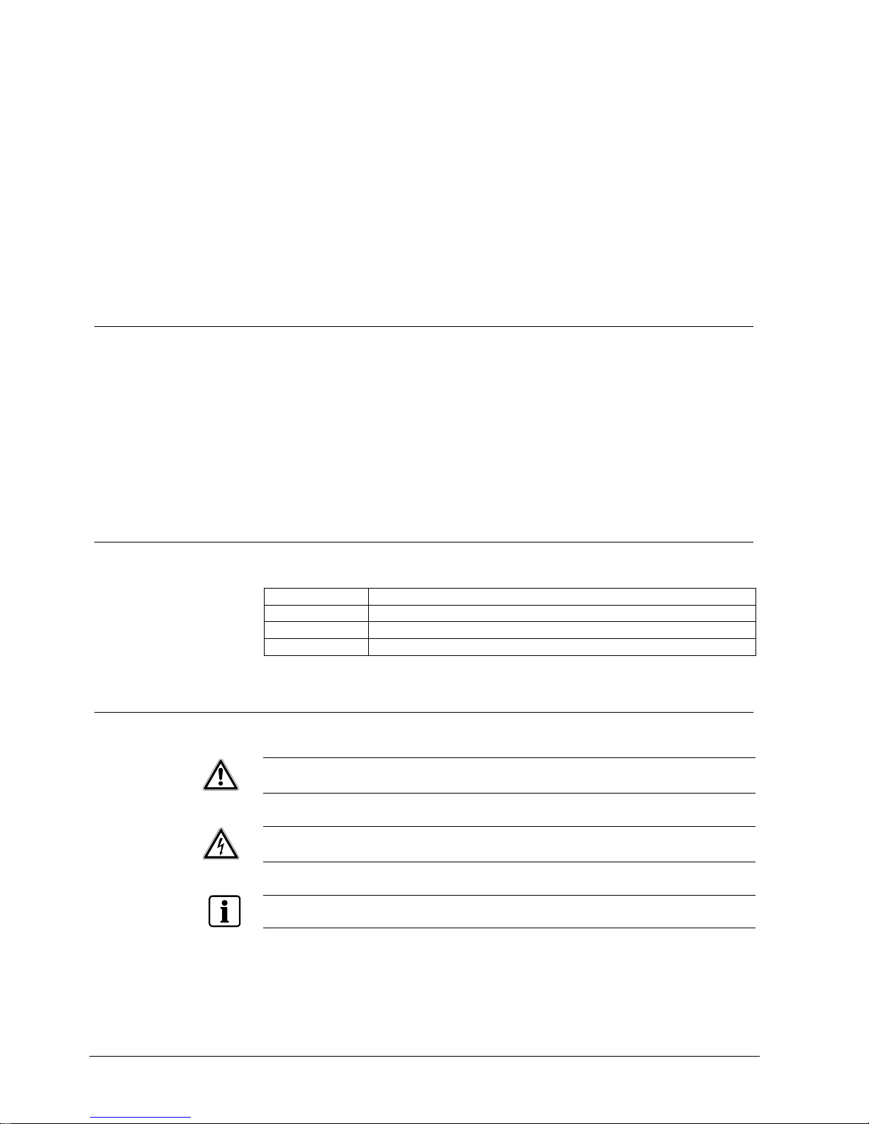
1.3 Meaning of the written warning notices
The severity of a hazard is indicated by the following written warning notices.
Warning notice Type of risk
WARNING Death or severe bodily injury may result
CAUTION There is a risk of minor injuries or damage to property
IMPORTANT Malfunctioning may result
1.4 Meaning of the hazard symbols
The nature of the hazard is indicated by icons.
CAUTION Dangerous area!
CAUTION Dangerous electrical voltage!
Important information
Page 7

Directives and standards
7
Siemens AG 04.2011
2 Directives and standards
The product complies with the requirements of the following EU directives. The EU
declaration of conformity is available from:
Siemens AG
Siemensallee 84
76181 Karlsruhe
European Directive 2004/108/EC "Electromagnetic Compatibility"
Compliance with the European Directive 2004/108/EC has been proven by testing
according to the following standard:
Emitted interference: EN 55022 Class A
Resistance to interference: EN 50130-4
CAUTION
This is a Class A device. This equipment may cause radio interference in a
residential installation. In this case the user is encouraged to perform
appropriate measures to correct the interference.
Page 8

Technical data
8
Siemens AG 04.2011
3 Technical data
A
B
C
121.4
72.0
66.0
23.031.0
20.0
1
Abb. 1 Dimensions
1 ¼-inch 20 UNC female thread
A Front view
B Side view
C Bottom view
Power supply
Power requirement 12 V DC / 24 V AC, 0.6 A, 50 Hz
General
Image sensor ¼-inch SONY 760H EXview HAD CCD
Pixels 795 (H) x 596 (V)
Scanning system 2:1 interlace
Scanning frequency 15,625 kHz (H), 50 Hz (V)
Synchronization Internal/external: line lock
Horizontal resolution Colour: 560 TV lines
B/W: 600 TV lines
Min. illumination Colour: 0.5 lux
B/W: 0.05 lux
Slow shutter: 0.001 lux
0.5 lux at F=1.6 (AGC on, 50 IRE video output)
Video output 1.0 Vpp (75 Ω, composite)
Signal/noise ratio 50 dB (AGC off)
Functions
Wide dynamic range (WDR) On/Off/Level (x512, 48 dB)
Back-light compensation (BLC) Auto/Manual (Area, Level)/Off
Day/night Colour/BW/Auto/EXT
Page 9

Technical data
9
Siemens AG 04.2011
Motion detection (MD) On/Off (Area/Sensitivity)
Slow-speed shutter 2x – 128x
Digital noise reduction (DNR) 2D/3D
Face detection (FD) On/Off
Privacy masking (PM) Max. 16 zones, mosaic function
White balance (WB) AWB/WAWB/Indoor/Outdoor/Manual/CRS
(Colour Rolling Suppression)
Auto exposure (AE) Auto1/Auto2/Shutter Priority/Manual
Iris control Automatic
Automatic gain control (AGC) MIN/LOW/MID/HIGH (max. 30 dB)
Shutter speed Normal: 1/100000 s
Title A – Z / 0 – 9
Display On/Off/Push On (DISP1/DISP2)
Brightness Adjustable in steps from 10 – 50
Sharpness Adjustable in steps from 0 – 15
Zoom presets 10
Zoom tour 1 tour / 10 presets
Alarm mode On/Off/Dwell Time
Remote configuration RS-232: Siemens B (parameter setting)
RS-485: Siemens B, S; Molynx; Pelco D/-P
Bit rate 2400/4800/9600/19200
Camera ID 1 – 255
Effect Sharpness, Nega/Posi, D-FLIP, Freeze,
HI-RES, 2-3 DNR
Home preset Off/Home Preset Select/Dwell Time
Lens
Focus mode Auto/Manual/Push AF
Distance 0.1 m/1.0 m/1.5 m/2.5 m/6.0 m
Total zoom 22x optical zoom, 16x digital zoom (video AF)
Focal length 3.9 – 85.8 mm
Aperture F1.6 (wide-angle) – F3.7 (tele)
Angle of view Horizontal: 49.5° (wide-angle) – 2.6° (tele)
Connections and environmental conditions
Power input 2-pin connection terminal
Video output BNC connector / TP output
Environmental operating
temperature
-10 to +50 °C
Relative humidity 0 – 96% (non-condensing)
Storage temperature -20 to +60 °C
Dimensions (W x H x D) 72 x 66 x 121.4 mm
Weight 0.40 kg
TP output
Video output Adjustable: 2.0 Vpp, 2.6 Vpp, 3.2 Vpp
Frequency accentuation Adjustable: 0 dB, 6 dB, 12 dB
Page 10

Details for ordering
10
Siemens AG 04.2011
4 Details for ordering
Type Part no. Designation Weight
CCAW1417-LPI S54561-C34-A1 ¼-inch Camera D/N WD AF 0.4 kg
5 Package contents
z Camera
z Installation Instruction
z 12-pin interface cable
z Software and documentation on CD
Page 11

Description of the camera
11
Siemens AG 04.2011
6 Description of the camera
6.1 Camera features
The high-resolution, day/night, autofocus all-in-one camera is particularly suited for
closed circuit television (CCTV) and security surveillance applications.
z High-performance SONY ¼-inch 760H EXview HAD CCD
z 352x zooming capability (optical: 22x / digital: 16x)
z Ultra-sensitivity minimum illumination of 0.5 lux at F1.6
(AGC on, 50 IRE video output)
z Excellent picture quality
z Various picture effects
z Flexible configuration
z Camera control via RS-485
z Twisted-pair video output
z Dual-power operation 12 V DC / 24 V AC
CAUTION Use only certified class 2 power supply units.
Functions:
z Day/Night (D/N)
z Wide dynamic range (WDR)
z Digital noise reduction (DNR)
z Auto exposure (AE)
z Back-light compensation (BLC)
z Digital zoom (D-Zoom)
z Day/Night switching (D/N)
z Freeze
z Digital slow shutter (DSS)
z Automatic white balance (AWB)
z Automatic gain control (AGC)
z On-screen menu (OSD)
z Negative/Positive switching (NEGA/POSI)
z E function (H/V flip, rotation)
z High resolution
z Motion detection and face detection
z Privacy masking
z Zoom preset and tour function
z Home preset
Page 12

Description of the camera
12
Siemens AG 04.2011
CAUTION
The user of this camera is responsible for checking and complying with local,
state, and federal laws and statutes concerning the recording and monitoring of
audio and video signals.
6.2 Camera parts
8
9
7
3
5
6
4
13
15
10
11
12
14
1
2
Abb. 2 Camera parts definition
1 Zoom lens Integrated lens with 22x optical zoom
2 Filter mount For standard filters with diameter 37 mm
3 Front part of the
housing
4 Mounting adapter For mounting the camera, ¼-inch 20 UNC thread
5 Housing body
6 Rear part of the housing
7 Camera module
8 Connector Connection of control signals
9 TELE, WIDE keys Press "WIDE" for wide-angle view and "TELE" to zoom in
10 MENU key Press to activate the OSD menu
11 NEAR, FAR keys Press the "NEAR" button to focus on near objects and the "FAR"
button to focus on distant objects. The focus keys are activated when
AF mode is Off.
12 BNC connector Monitor connection port
13 Power input terminal 24 V AC / 12 V DC
14 Power indicator LED
15 DIP switch Twisted-pair video output parameters
A Front view
B Side view
C Rear view
Page 13

System installation
13
Siemens AG 04.2011
7 System installation
Installation of the camera must be performed by qualified service personnel in
accordance with all local national electrical and mechanical codes.
Typical system configuration with DVR Typical system configuration with SIMATRIX
1
1
1
C1
C2
C10
A
B
B
234
C
1
1
1
.....
C1
C2
C10
A
B
2
4
3
C
1 Camera C1..C10 A RS485
2 Keyboard B Video
3 DVR C RS232/485
4 Monitor
1 Camera C1..C10 A RS485
2 Keyboard B Video
3 SIMATRIX C TTY
4 Monitor
When using the camera in conjunction with a video matrix switcher (SIMATRIX SYS, 648, 164) or
other telemetry equipment (different protocol), an interface converter CAC0103 is required.
Typical system configuration with directly controlled cameras
1
1
.....
C1
C2
C10
2
3
33
B
B
B
A
1 Camera C1..C10 A RS485
2 Keyboard B Video
3 Monitor
Page 14

Connection
14
Siemens AG 04.2011
8 Connection
CAUTION
Do not connect the power cable until all other connections have been
completed. Any unused wires should be trimmed and insulated.
Abb. 3 Connection
1 Monitor BNC
2 Video BNC
3 DVR/VCR BNC
A Pink RS-485(-) 4 RS-485 connection
B Black RS-485(+)
C Blue TP-A(+) 5 Twisted-pair video output
D Green TP-B (-)
E Grey Ext. input 6 Aut. switching between
colour and B/W /
Alarm input
F Red GND
G Yellow GND 7 Remote control
H Orange Control
Light blue TxD RS-232 connection,
PC configuration
Brown RxD
MD output Violet MD/FD off: 0 V, on: 3.3 V
Red +12 V DC / 24 V AC Power supply
White - 12 V DC / 24 V AC
Page 15

Connection
15
Siemens AG 04.2011
8.1 General
8.1.1 Automatic switching between colour and B/W mode
The camera must be connected to an external sensor to receive day/night
detection signals.
2
3
4
1
1 External sensor switch
2 External input (EXT-In) Grey
3 External output (EXT-Out) White
4 GND Red
Positions of the external sensor switch (1)
Activate alarm: closed
EXT-IN
Deactivate alarm: open
Alarm activated: 5 V
EXT-OUT
Alarm deactivated: 0 V
To activate the sensor inputs, select the mode EXT in the function menu B/W.
8.1.2 RS-485 connection
The camera can be controlled remotely by an external device or control system,
such as a control keyboard, using RS-485 half-duplex. Connect marked Rx+, Rxto Tx+ and Tx- of the RS-485 control system.
1 RS-485(+) Black
2 RS-485(-) Pink
Page 16

Connection
16
Siemens AG 04.2011
8.1.3 Twisted-pair video output
1 TP-A(+) Blue
2 TP-B (-) Green
Switch description S1 S2 S3 S4 Note
Off Off 2.0 Vpp
On Off 2.6 Vpp
Output voltage without
accentuation
On On 3.2 Vpp
Off Off 0 dB
Off On 6 dB
On Off 6 dB
Frequency-dependent
accentuation at 5 MHz
On On 12 dB
ON
1234
Condition on delivery On Off Off Off
8.1.4 Alarm output
The alarm output (motion detection result or face detection result or external signal
fed in) is active high.
1 Alarm output Violet
2 GND Red
Page 17

Connection
17
Siemens AG 04.2011
8.2 Remote configuration
3
1
1
2
2
1
1
2
2
1
1
2
2
1
1
2
2
1
1
2
2
R22
150
R20
12K
R21
5.6K
Sw10
TELE
R19
22K
Sw11
WIDE
Sw13
FAR
Sw12
NEAR
R18
33K
Sw9
MENU
1
2
A
3
MENU
TELE
NEAR
FAR
WIDE
4
3
1M95mm
42mm
4
Abb. 4 Remote configuration – circuit diagram
Camera
1 GND Yellow
2 Remote control Orange
Remote control unit
3 Remote control White
4 GND Black
A Remote control unit
The remote control cable must not be extended.
Page 18

Camera settings
18
Siemens AG 04.2011
9 Camera settings
9.1 OSD main screen
CAMERA TEXT
001x CAM 001
1
23
1 Camera title
2 Status of the zoom position
3 Camera ID
9.2 Main menu
<MAIN MENU>
FOCUS
WB
AE
BLC/WDR
ALARM/MD/FD
PRIVACY
SPECIAL
EFFECT
CAM SET
END <EXIT>
Navigate the camera menu using the remote control (see Section 8.2 Remote configuration).
9.2.1 FOCUS
<FOCUS MENU>
MODE
DISTANCE
D-ZOOM
D-ZOOM END
ZOOM PRESET
SET PRESET
TOUR CONFIG
HOME PRESET
HOME DWELL
END
MODE Focus mode: Auto, Manual, PushAF
DISTANCE Min. distance in focus between camera and object
D-ZOOM 0.1 / 1.0 / 1.5 / 2.5 / 6.0 m
D-ZOOM END Digital zoom function On/Off
ZOOM PRESET Max. digital zoom factor: x2 – x16
SET PRESET Zoom preset number: 1 – 10
Page 19

Camera settings
19
Siemens AG 04.2011
TOUR CONFIG Zoom position of zoom preset
HOME PRESET Press ENTER to save the tour configuration (preset combination)
HOME WAIT Home preset On/Off
END Waiting time after which the camera returns to start position (HOME PRESET)
Move the cursor using the "Far/Near", "Tele/Wide" keys.
Press MENU to enter the next level for configuration.
12
<TOUR CONFIG MENU>
01* 02* 03 04 05
06 07 08 09 10
< S E
DWELL TIME 010
CMD description
* : User-saved preset
< : Deletes the character at the cursor position and
moves one position to the left
S : Save the present tour setting
E : Exit
DWELL TIME
Zoom preset dwell time (10 – 180 s)
When ZOOM PRESET is selected, you can adjust the preset zoom position using the “Tele” and
“Wide” buttons.
When a ZOOM PRESET has been selected press the MENU button to save the preset.
9.2.2 WB (White Balance)
<WB MENU>
MODE
R GAIN
B GAIN
FRAME ADJ
END
MODE WB modes:
z AWB: Auto White Balance: 2500K – 9500K
z WAWB: Wide Auto White Balance: 1800K – 10500K
z INDOOR: Indoor white balance mode
z OUTDOOR: Outdoor white balance mode
z MANUAL: You can change R and B gain manually
z CRS (Colour Rolling Suppression): Decrease colour rolling effect; useful in
SHUTTER mode in AE menu
R GAIN Red gain: 0 – 255
B GAIN Blue gain: 0 – 255
FRAME ADJ Since the colour rolling path differs depending on the fluorescent lamp used, it has to
be adjusted individually. To do so, select the WB menu.
After about 10 s, the adjust mode will be finished automatically.
END Back to the next higher menu level
Page 20

Camera settings
20
Siemens AG 04.2011
9.2.3 AE (Auto Exposure)
<AE MENU>
MODE
SHUTTER
GAIN
DSS
MAX DSS
FLICKERLESS
BRIGHTNESS
END
MODE AE modes:
z Auto1: For use in normal environments: Indoor (shutter speed 1/50 s)
z Auto2: For use in high-brightness environments: Outdoors
z Shutter Pri.: Shutter priority exposure mode
z Manual: Manual exposure mode
SHUTTER Shutter speed: 1/50 – 1/100 000 s
Can be changed while in "Shutter Pri" and "Manual" mode
GAIN Maximum Auto Gain Control (AGC) value
DSS Digital slow shutter On/Off (enable in low light)
MAX DSS Digital slow shutter range: x2 – x128
FLICKERLESS Flicker-less function On/Off
BRIGHTNESS Brightness level: 10 – 50
END Back to the next higher menu level
9.2.4 BLC / WDR (Back Light Compensation / Wide Dynamic Range)
<BLC/WDR MENU>
BLC MODE
AREA
LEVEL
WDR MODE
LEVEL
END
1 2 3
4 5 6
7 8 9
<BLC area number>
BLC MODE BLC mode: OFF, AUTO, MANUAL:
AUTO: Automatic back-light compensation (area & level)
MANUAL: Back-light compensation (area & level reserved)
BLC AREA Select BLC area: 1-9, activated only in manual BLC mode
BLC LEVEL Back-light compensation level: LOW, MID, HIGH
WDR MODE WDR (Wide Dynamic Range) function On/Off
WDR LEVEL WDR level: 10 – 50
END Back to the next higher menu level
Page 21

Camera settings
21
Siemens AG 04.2011
9.2.5 ALARM / MD (Motion Detection) / FD (Face Detection)
<ALARM/MD/FD MENU>
MODE
AREA SEL
DEFAULT
ADJ TOP/LEFT
ADJ BOT/RIGHT
SENSITIVITY
DWELL TIME
PRESET SEL
END
MODE ALARM and MD/FD mode: MD/EXT/FD/MD+EXT/FD+EXT
AREA SEL Area number: 1 – 4, MD/FD On/Off
DEFAULT Default setting for motion area
ADJ TOP/LEFT Adjust the location of the MD area with boundary top and left
ADJ BOT/RIGHT Adjust the location of the MD area with boundary bottom and right
SENSITIVITY Adjust sensitivity of MD/FD: MD: 1 – 10 / FD: 1 – 64
DWELL TIME Dwell time setting of zoom preset: 10 – 180 s
PRESET SEL Zoom preset number: Off, 1 – 10
END Back to the next higher menu level
The quality of face detection depends on the environmental conditions.
9.2.6 PRIVACY
<PRIVACY MENU>
MASK SEL
DEFAULT
ADJ TOP/LEFT
ADJ BOT/RIGHT
COLOUR
MOSAIC
MOSAIC TYPE
END
MASK SEL Mask area number: 1 – 16
Mask On/Off
DEFAULT Default setting for mask area
ADJ TOP/LEFT Adjust the location of the mask area with boundary top and left
ADJ BOT/RIGHT Adjust the location of the mask area with boundary bottom and right
COLOUR Mask colour: 1 – 8
MOSAIC Mosaic display On/Off
MOSAIC TYPE Mosaic roughness setting: 1 – 4
END Back to the next higher menu level
Page 22

Camera settings
22
Siemens AG 04.2011
9.2.7 SPECIAL
<SPECIAL MENU>
SYNC
PHASE
D/N MODE
D/N DELAY
WHITE DET.
LEVEL
END
SYNC INTERNAL or LINE LOCK mode
PHASE Adjust SYNC PHASE in LINE LOCK MODE
D/N MODE D/N, COLOUR, BW, or EXT mode
D/N DELAY Delay of IR filter in D/N mode: 5 s, 10 s, 20 s
WHITE DET Start of white pixel detection function. The iris will be closed automatically and
return to the normal state once white detection is finished.
LEVEL Threshold level: 1 – 15
END Back to the next higher menu level
9.2.8 EFFECT
<EFFECT MENU>
SHARPNESS
NEGATIVE
D-FLIP
FREEZE
HI-RES
2DNR
3DNR
END
SHARPNESS Image sharpness: 0 – 15
The lower the value, the softer the image, and the higher the value, the sharper
the image
NEGATIVE Negative or positive mode
D-FLIP Digital flip function: vertical flip/horizontal flip/180° rotation
FREEZE Real or still mode
HI-RES High-resolution mode: Low/Mid/High
2DNR 2D noise reduction level: Off/01 – 07
3DNR 3D noise reduction level: Off/01 – 31
END Back to the next higher menu level
Page 23

Camera settings
23
Siemens AG 04.2011
9.2.9 CAMSET
<CAMSET MENU>
CAM ID
BAUD RATE
PROTOCOL
DISP MODE
DISP ITEM
TITLE
ALARM TEXT
SAVE
END
CAM ID Camera ID: 1 – 255
BAUD RATE Serial communication speed: 2400/4800/9600/19200
PROTOCOL Operating protocol:
z COMMAND: for factory use only
z SIEMENS – B (Parity = Even)
z SIEMENS – S (Parity = Even)
z MOLYNX (Parity = Even)
z PELCO – D (Parity = None)
z PELCO – P (Parity = None)
DISP MODE OSD display mode: Off/Push, On/On
DISP ITEM Display elements:
1: Camera title and camera number
2: Camera title, zoom factor and camera number
TITLE Press ENTER to configure camera name
ALARM TEXT Press ENTER to configure alarm text
SAVE Press ENTER to save CAMSET configuration
END Back to the next higher menu level
Move the cursor using the "Far/Near", "Tele/Wide" keys.
Press the MENU key to open a sub-menu.
TITLE TEXT
<TITLE MENU>
A B C D E F G H I J
K L M N O P Q R S T
U V W X Y Z 0 1 2 3
4 5 6 7 8 9 ( ) :
; . - ! < > , `
CMD < > S E
CMD description
← : One position to the left
→ : One position to the right
< : Deletes character at cursor position and
moves to the left
> : Deletes character at cursor position and
moves to the right
S : Save the present setting
E : Exit
If you make any changes in the BPS or PROTOCOL submenus, be sure to select SAVE PROTOCOL
& BPS to save your changes.
Do not disconnect the camera from the power source while saving.
Page 24

Troubleshooting and maintenance
24
Siemens AG 04.2011
10 Troubleshooting and maintenance
10.1 Troubleshooting
If problems occur, check to ensure the camera is installed in accordance with the
instructions in this manual. Isolate the problem to a specific piece of equipment in
the system and refer to the equipment manual for further information.
PROBLEM POSSIBLE SOLUTION
Nothing appears on the screen. Are all cables between the camera and the monitor
connected properly?
The image on the screen is too dark. Is the lens dirty?
If so, clean the lens with a soft, clean cloth.
The camera is not working properly and
the surface of the camera case is hot.
Is the camera connected to the proper power source?
The contrast on the screen is too weak. Adjust the contrast feature of the monitor. Is the camera
exposed to strong light? If so, change the camera
position.
10.2 Maintenance
Preventive maintenance allows minor faults to be detected and corrected before
they become serious and cause equipment failure. Therefore, the following
maintenance tasks should be performed on a three-monthly basis:
z Inspect all connection cables for deterioration or other damage.
z Clean all components with a soft, clean cloth.
z Check that all fixings are secure.
Page 25

Disposal
25
Siemens AG 04.2011
11 Disposal
All electrical and electronic products should be disposed of separately from the
municipal waste stream via designated collection facilities appointed by the
government or the local authorities.
This crossed-out wheeled bin symbol on the product means the product is
covered by the European Directive 2002/96/EC.
The correct disposal and separate collection of your old appliance will help
prevent potential negative consequences for the environment and human health.
It is a precondition for reuse and recycling of used electrical and electronic
equipment. For more detailed information about disposal of your old appliance,
please contact your city office, waste disposal service or the shop where you
purchased the product.
Page 26

Issued by
Siemens AG
Siemensallee 84
D-76187 Karlsruhe,
Tel. +49 721 595 1
www.buildingtechnologies.siemens.com
© 2011 Copyright by Siemens AG
Data and design subject to change without notice.
Supply subject to availability.
Document No. A6V10321762
Edition 19.04.2011
 Loading...