

Siemens BB814 Datasheet
BB 814
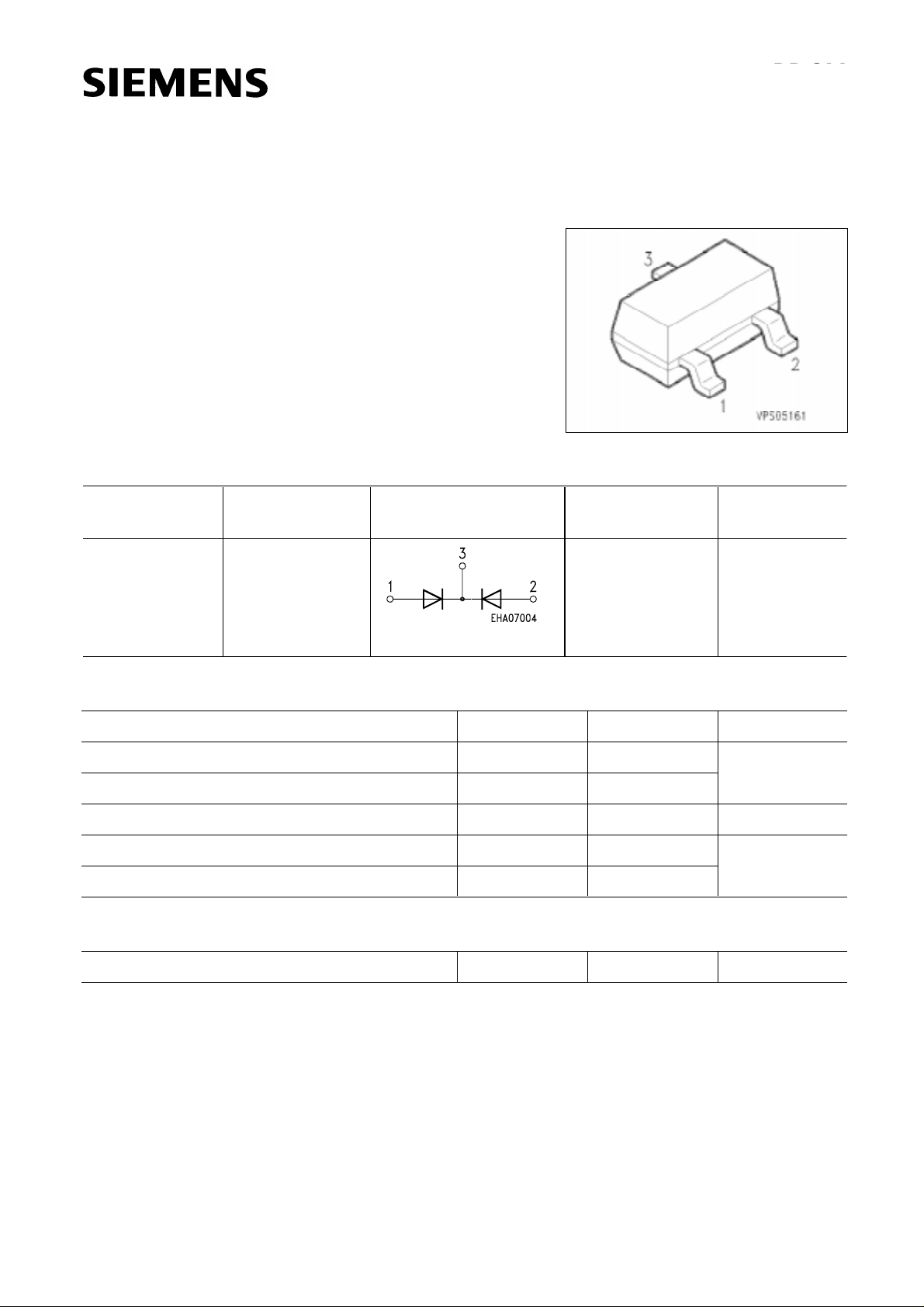
Silicon Variable Capacitance Diode BB 814
● For FM radio tuners
with extended frequency band
● High tuning ratio at low supply voltage
(car radio)
● Monolithic chip (common cathode)
for perfect dual diode tracking
● Coded capacitance groups and
group matching available
Type Ordering Code
Pin Configuration PackageMarking
(tape and reel)
BB 814 Q62702-B404 SH (see
SOT-23
Characteristics
for marking of
capacitance
subgroups)
Maximum Ratings per Diode
Parameter Symbol Values Unit
Reverse voltage V
R 18 V
Peak reverse voltage VRM 20
Forward current, TA ≤ 60 ˚C IF 50 mA
Operating temperature range T
Storage temperature range T
op – 55 … + 125 ˚C
stg – 55 … + 150
Thermal Resistance
Junction - ambient R
Semiconductor Group 1
th JA ≤ 600 K/W
10.94

Electrical Characteristics
A = 25 ˚C, unless otherwise specified.
at T
BB 814
Parameter Symbol
DC Characteristics
Reverse current
R = 16 V
V
R = 16 V, TA = 60 ˚C
V
Diode capacitance
f = 1 MHz
1)
R nA
I
CT pF
VR = 2 V
R = 8 V
V
Capacitance ratio
R = 2 V, 8 V, f = 1 MHz
V
Capacitance matching
R = 2 V, 8 V
V
Series resistance
R = 2 V, f = 100 MHz
V
Q factor
R = 2 V, f = 100 MHz
V
C
T2
CT8
∆CT
CT
r
S
Q
min. typ.
–
–
43
19.1
–
–
44.75
20.8
––
–
–
0.18
200
max.
20
200
46.5
22.7
3
–
–
UnitValues
–2.05 2.15 2.25
%
Ω
–
1)
Capacitance groups, coded 1, 2
Code C
1 43 … 45 19.1 … 21.95
2 44.5 … 46.5 19.75 … 22.7
T (2 V)
C
T (8 V)
Unit
pF
pF
Semiconductor Group 2
 Loading...