

Page 1

QPA63 Series
CO2/VOC Sensors
Technical Instructions
Document No. CM1N1958E-P25
November 21, 2006
QPA63.1 QPA63.2
Description
Application
Sensors designed for sensing indoor air quality in rooms or air du cts; microprocessorbased units consisting of a selective photo-acoustic CO
with a heated stannic dioxide semiconductor.
Operating voltage: 24 Vac
Output signals: 0 to 10 Vdc
The QPA63 VOC Sensor can detect any of the following gases:
Alcohol Ethylene Oxide n-Hexane 2
Acetone Formaldehyde n-Patene
Acrylonitriles Hydrogen Propane
Ammonia Hydrogen Sulfide R-11
Benzene Isobutane R12
Carbon Dioxide Methane R123
Carbon Monoxide Methanol R502
Chlorides Methyl Acetate Sulfur Dioxide
Dimethyl Amines Methyl Chloride Vinyl Chloride
Ethane Methyl Ether
Ethylene Methyl Ketone
1. VOC = Volatile Organic Compounds (also called mixed gas)
The QPA63 Series sensors are used in HVAC applications to enhance room comfort
and to optimize energy consumption by providing demand-controlled ventilation.
sensor and a VOC1 sensor
2
The sensor monitors the following:
• • CO
concentration as an indicator for occupancy in rooms where smoking is
2
prohibited.
VOC concentration as an indicator for combustible gases and room odors (tobacco
smoke, body odor, material fumes) in the air.
Siemens Building Technologies, Inc.
Page 2

Technical Instructions QPA63 Series CO2/VOC Sensors
Document Number CM1N1958E-P25
November 21, 2006
Application,
Continued
Product Numbers
The sensor can be used as the following:
•
Room sensor to measure room air quality.
•
Duct sensor in conjunction with the ARG64 duct mo unting kit to measure
exhaust air quality.
Typical areas of use:
•
Measuring CO
and VOC concentration.
2
In party rooms, lounges, exhibition halls, restaurants, canteens, shopping malls,
gymnasiums, sales rooms, and conference rooms. In this case, the AQP63.1
ventilation demand processor, which calculates the ventilation demand signal for the
ventilation controller based on the CO
and VOC signal, is required. For more
2
information on the AQP63.1, see Technical Instructions (CM1N1959E-P25).
• Measuring CO
concentration.
2
In rooms with varying occupancy at different hours where smoking is prohibited
such as museums, theaters and auditoriums.
NOTES: 1. The sensors cannot be used as safety devices, such as gas or smoke
warning devices.
2. The sensors cannot be used on rooftop air ducts (solar radiation).
Table 1.
Product Number Description
QPA63.1
QPA63.2
CO
/VOC Sensor Without LEDs
2
CO
/VOC Sensor With LEDs
2
ARG64 Duct Mounting Kit for QPA63 Series
ARG70 Wall Mounting Kit for QPA63 Series
Ordering
Compatibility
You must order the ARG64 Duct Mounting Kit separately.
The sensors are suited for use with all systems, controllers and devices capable of
acquiring and handling the 0 to10 Vdc output signal.
Function
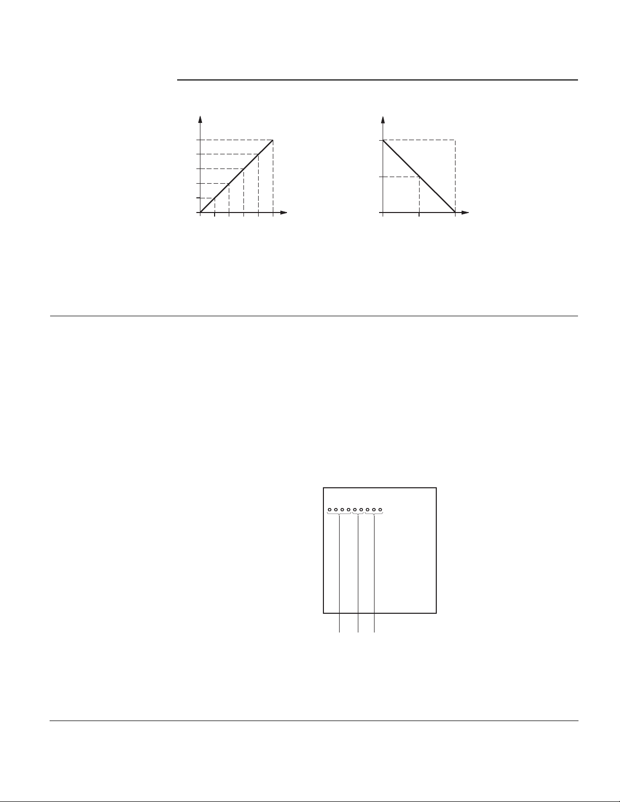
The sensor detects the CO2 and VOC concentrations in the room or in the exhaust air
duct.
The CO
(connection terminal U2) is proportional to the CO
concentration is evaluated by the sensor. The output signal delivered
2
content of the ambient air.
2
The number of LEDs lit is proportional to the CO2 concentration. The poorer the air
quality, the more LEDs are lit.
The acquired VOC concentration is also passed on to a sensor output (connection
terminal U1). The output signal provided is inversely proportional to the concentration of
oxidizable gases (VOCs), such as tobacco smoke, CO, alcohol and body odo rs. This
means that when the VOC concentration increases, the signal voltage will drop towards
0V, and when the VOC concentration decreases, the signal voltage will rise towards
10V. The AQP63.1 is required to evaluate the output signal.
Page 2 Siemens Building Technologies, Inc.
Page 3
QPA63 Series CO2/VOC Sensors Technical Instructions
Document Number CM1N1958E-P25
November 21, 2006
Function, Continued
CO2 Output VOC Output
10
8
6
4
2
0
U2 [V]
0
400
800
1200
1600
2000
CO
[ppm]
2
10
5
0
U1
clean
air
[V]
polluted
SSEN0006R1
VOC concentration
air
Legend:
U1 Signal voltage at output U1 (VOC) in volts
U2 Signal voltage at output U2 (CO
) in volts
2
1 ppm = 1 part per million
Figure 1. Function Diagram.
Mechanical Design
The sensors have been designed for wall mounting. They are suitable for use with most
commercially available recessed conduit boxes. The cables can be introduced from the
Sensor QPA63…
rear (concealed wiring) or from below or above (surface-mounted wires) through
knockout openings.
All terminals are protected against incorrect wiring.
The units consist of two major parts: four-sectional housing and base. Both snap
together, but can be detached again.
The housing accommodates two sensing elements, the electronics and d epending on
the type of sensor, various setting elements and LEDs.
Connection terminals are in the base.
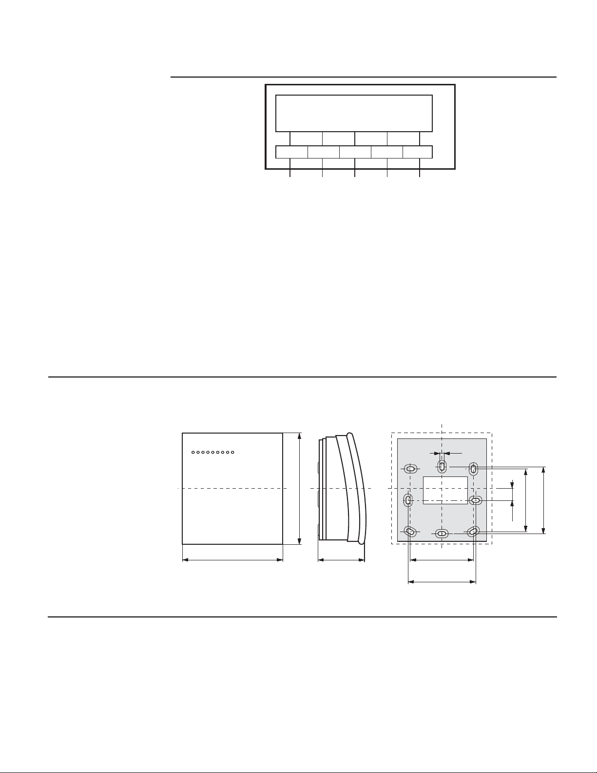
Front View
SSEN0015R1
123
Legend:
1 Green LEDs = 0 to 1000 ppm CO
2 Yellow LEDs = 1000 to 1400 ppm CO
3 Orange LEDs = 1400 to 2000 ppm CO
2
2
2
Figure 2. Indicator Lights (Only with QPA63.2).
Siemens Building Technologies, Inc. Page 3
Page 4
Technical Instructions QPA63 Series CO2/VOC Sensors
Document Number CM1N1958E-P25
November 21, 2006
Duct Mounting Kit
ARG64
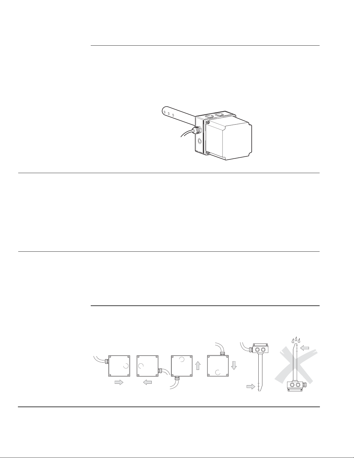
The duct mounting kit has been designed to mount the sensor in an exhaust air duct.
The kit consists of a two-section plastic housing and an attached metal rod with a
clamped-on, adjustable duct-mounting flange. There is an air inlet (three holes) and an
air outlet at the bottom of the rod. The sensor mounting plate is installed in the lower
part of the housing; the plate corresponds to the mounting plate of the QPA63... The
upper part of the housing consists of a high, grey, removable cover, rubber seal and
four mounting screws. The housing is supplied complete with a ready wired five-wire
connecting cable.
Engineering Notes
Mounting
Sensor QPA63…
Room mounting
Duct mounting with an
ARG64 duct mounting kit
SSEN0331R1
Figure 3. ARG64.
• • The CO2/VOC sensors cannot be used for safety-related measurements of gas
concentrations.
The CO
/VOC sensors cannot be used for rooftop air ducts (solar radiation).
2
Duct mounting with an ARG64:
1. Install the rod in the direction of flow. Do not twist more than 10°.
2. Maximum permissible air velocity in the duct = 16 feet/second (5 m/second).
3. Maximum permissible temperature inside and outside the duct:= 95°F (35°C)
4. Minimum duct immersion depth = 6-11/16 inches.
When mounting in a room, a location with typical air quality should be chosen such as
on an open wall, approximately five to ten feet (1.5 to 3 m) above the floor. The sensor
should not be mounted in niches, shelves, behind curtains, and so on, or in locations
where people are constantly present.
Observe permissible ambient conditions.
Mounting instructions are included.
Install the rod in the exhaust air duct as close as possible to the air outlet, in the
direction of flow.
Mounting instructions are included in the mounting kit.
SSEN0016R1
Figure 4. Permissible and Non-permissible Mounting Positions.
Page 4 Siemens Building Technologies, Inc.
Page 5

QPA63 Series CO2/VOC Sensors Technical Instructions
Document Number CM1N1958E-P25
November 21, 2006
Commissioning
Notes
Check the CO2/VOC sensor functions 30 minutes after applying operating voltage as
follows:
•
Check the CO
•
Check the VOC function: touch the sensor with a cotton ball dowsed in alcohol
function: exhale on the sensor.
2
(possibly gas from lighter, without flame).
Ventilation should start as soon as the preset switching level of the connected controller
is reached.
After supplying power to the QPA63.2, the LEDs will flash for about one minute.
Specifications
Power Supply
Operating voltage (Class 2) 24 Vac ± 20%
Frequency 50/60 Hz
Power consumption Maximum 6 VA
Range of use CO2 measuring range 0 to 2000 parts per million
CO
tolerance ± 100 ppm
2
VOC measuring range 0 to 10 V
VOC
Permissible air velocity in the duct <16 feet per second
(<5 m per second)
Electrical Voltage 0 to 10 Vdc
Current ± 1 mA
Permissible wire lengths:
Copper cable 20 AWG 197 feet (60 m)
Copper cable 18 AWG 722 feet (220 m)
Copper cable 16 AWG 984 feet (300 m)
Copper cable 14 AWG 1,475 feet (450 m)
Connection Terminals Screw terminals for 2 × 16 AWG or 1 × 14 AWG
Environmental Conditions Operation
Temperature
Wall mounting 23°F to 113°F (−5°C to 45°C)
Duct mounting 14°F to 95°F (− 10°C to 35°C)
Humidity (non-condensing) 5% to 95% rh
Transport
Temperature –13°F to 158°F (− 25°C to 70°C)
Humidity <95% rh
Weight QPA63… Approximately 0.22 lb (3.5 oz) [0.1 kg]
ARG64 1.5 lbs (24 oz) [0.69 kg]
Siemens Building Technologies, Inc. Page 5
Page 6

Technical Instructions QPA63 Series CO2/VOC Sensors
Document Number CM1N1958E-P25
November 21, 2006
Installation
Drywall Mounting
1. Place a small screwdriver into bottom of sensor and press in the two locking tabs
located in the second air vent to remove cover.
2. Remove sub-base from back of sensor.
3. Using the sub-base (packed with sensor) as a template, mark the hole locations
with a pencil.
4. Drill two 1/4-inch diameter holes for plastic wall anchors.
5. Using a mallet, tap in the plastic wall anchors flush with wall.
6. Pull the wiring through the opening in the upper portion of the sub-base.
7. Level mounting plate. Using two wood screws, fasten sub-base to wall. The sensor
is not position sensitive.
8. Pull the wiring through the sub-base.
9. Position sensor housing over the two mounting lugs located at the top of the subbase and press down on cover until bottom lugs snap in place.
10. Terminate wires per wiring instructions on the inside of sensor cover.
11. Insert the top of the sensor cover into the slots located on the top of the sensor and
press down until the two locking tabs snap into the second ventilation slot.
4 × 4-inch Electrical Wall
Box Mounting
See Figure 5
The installation is now complete.
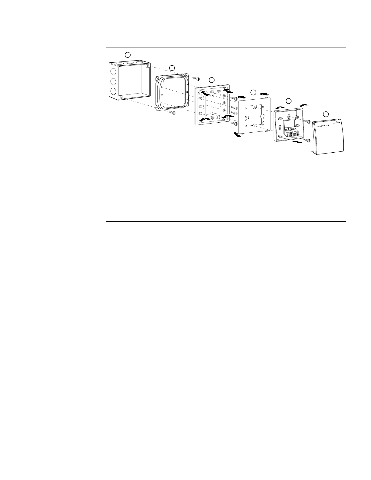
An ARG70 wall plate adapter is required to mount a QPA63 Series sensor to a 4 × 4-
inch electrical wall box. The ARG70 must be ordered separately.
1. Place small screwdriver into bottom of sensor and press in two tabs located in the
second air vent to remove cover.
2. Using the four screws provided, fasten wall box adapter (3) to plaster ring (2),
supplied by others.
3. Flex adapter mask (4) and snap in place inside wall box adapter (3).
4. Fasten sub-base (5), included with the QPA63, to wall box adapter assembly (3)
and (4) with the two screws provided.
5. Pull wires through plaster ring (2).
6. Follow Drywall Mounting Steps 6 through 11.
The installation is now complete.
Page 6 Siemens Building Technologies, Inc.
Page 7
QPA63 Series CO2/VOC Sensors Technical Instructions
Document Number CM1N1958E-P25
November 21, 2006
Installation,
Continued
1
2
3
4
5
6
8 7 6 5 4 3 2 1
SSENO314R1
Figure 5. 4 × 4-inch Electrical Wall Box Installation.
2 × 4-inch Electrical Wall
Box Mounting
See Figure 6
1 Electrical wall box
2 Plaster ring
3 Wall box adapter *
4 Adapter mask *
5 Sub-base
6 Sensor cover
* Included with ARG70
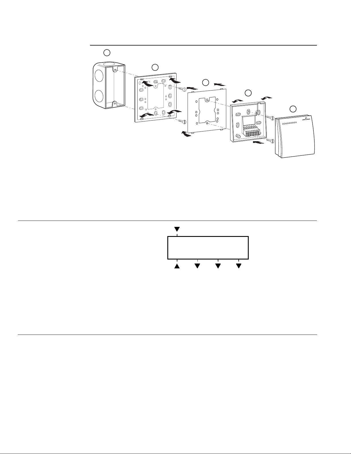
An ARG70 wall plate adapter is required to mount QPA63 Series sensor to a 2 × 4-inch
electrical wall box. The ARG70 must be ordered separately.
1. Place small screwdriver into bottom of sensor and press in two tabs located in the
second air vent to remove cover.
2. Using the two screws provided, fasten wall box adapter (3) to plaster ring (2),
supplied by others.
3. Flex adapter mask (4) and snap in place inside wall box adapter (3).
4. Fasten sub-base (5), included with the QPA63, to wall box adapter assembly (3)
and (4) with the two screws provided.
5. Pull wires through plaster ring (2).
6. Follow Drywall Mounting Steps 6 through 11.
The installation is now complete.
Siemens Building Technologies, Inc. Page 7
Page 8
Technical Instructions QPA63 Series CO2/VOC Sensors
Document Number CM1N1958E-P25
November 21, 2006
Installation,
Continued
1
SSENO315R1
Figure 6. 2 × 4-inch Electrical Wall Box Installation.
1 Electrical wall box
3 Wall box adapter *
4 Adapter mask *
* Included with ARG70
3
4
5
6
4 3 2 1
8 7 6 5
5 Sub-base
6 Sensor cover
Wiring Diagrams
(1)
G
VOC CO
M
SSEN0007R2
U1 U2
(2) (5) (4) (3)
Figure 7. Wiring Terminals.
G, M Operating voltage 24 Vac (Class 2)
G System potential
M System neutral
U1 Signal output "Measured value VOC", 0 to 10 Vdc
U2 Signal output "Measured value CO
2
M Measuring neutral (terminals M are interconnected inside the sensor)
2
M
", 0 to 10 Vdc
Page 8 Siemens Building Technologies, Inc.
Page 9
QPA63 Series CO2/VOC Sensors Technical Instructions
Document Number CM1N1958E-P25
November 21, 2006
Wiring Diagrams,
Continued
CO2 VOC
G
M
M
U2
U1
B1
Dimensions
All dimensions in inches
(millimeters)
12345
X1
A1
B2
(WH)
B1
(GY)
", 0 to 10 Vdc
2
M
(YE)
(BN)
SSEN0321R1
G
M
(GN)
Figure 8. ARG64 with QPA63… Wiring Diagram.
A1 Duct mounting kit ARG64
B1 CO
/VOC sensor QPA63...
2
X1 Terminal strip in the duct mounting kit ARG64
Wire code on connection cable of the ARG64:
G/brown (1) System potential 24 Vac (Class 2)
M/green (2) System neutral 24 Vac (Class 2)
M/yellow (3) Measuring neutral (System neutral)
B1/grey (5) Signal output "Measured value VOC", 0 to 10 Vdc
B2/white (4) Signal output "Measured value CO
NOTE: For individual panel wiring details, see the appropriate hardware manual.
SSEN0008R2
3.54
(90)
3.94
(100)
1.65
(42)
2.20
(56)
2.36
(60)
Figure 9. QPA63 Series Dimensions.
0.165
(4.2)
0.375
(9.5)
2.20
(56)
2.36
(60)
Siemens Building Technologies, Inc. Page 9
Page 10
Technical Instructions QPA63 Series CO2/VOC Sensors
Document Number CM1N1958E-P25
November 21, 2006
Dimensions,
Continued
All dimensions in inches
(millimeters)
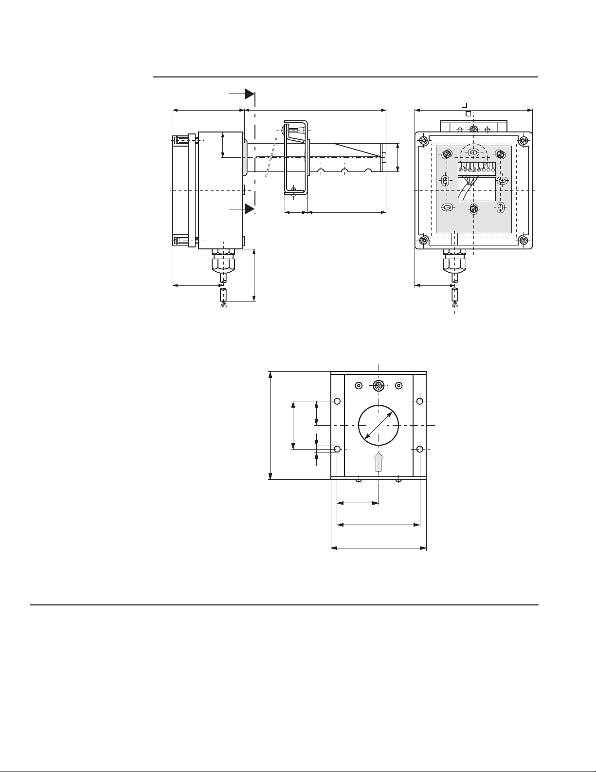
SSEN0009R2
2.11
(53.5)
4.92
(125)
A
1.08
B
(27.5)
12.60
(320)
59
0.98
(25)
(1500)
max. 11.61 (295)
min. 6.69 (170)
Figure 10. ARG64 Dimensions.
1.18
ø
30)
ø
(
4.92
( 125)
12345678
1.65
(42)
0.69
3.15
(80)
1.38
(35)
0.20
(17.5)
(5)
1.18
(30)
1.18
(30)
2.36
SEEN0010R2
(60)
2.76
(70.2)
Figure 11. Cross-section A – B Dimensions.
Page 10 Siemens Building Technologies, Inc.
Page 11
QPA63 Series CO2/VOC Sensors Technical Instructions
Document Number CM1N1958E-P25
November 21, 2006
Dimensions,
Continued
4.72(120)
0.91(23) 0.91(23)
4.21(107)
1.17(29.6) 1.1(28)
All dimensions in inches
(millimeters)
1.64(41.75)1.64(41.75)
0.91(23)0.91(23)
4.72(120)
TH0512R1
3.29(83.5)
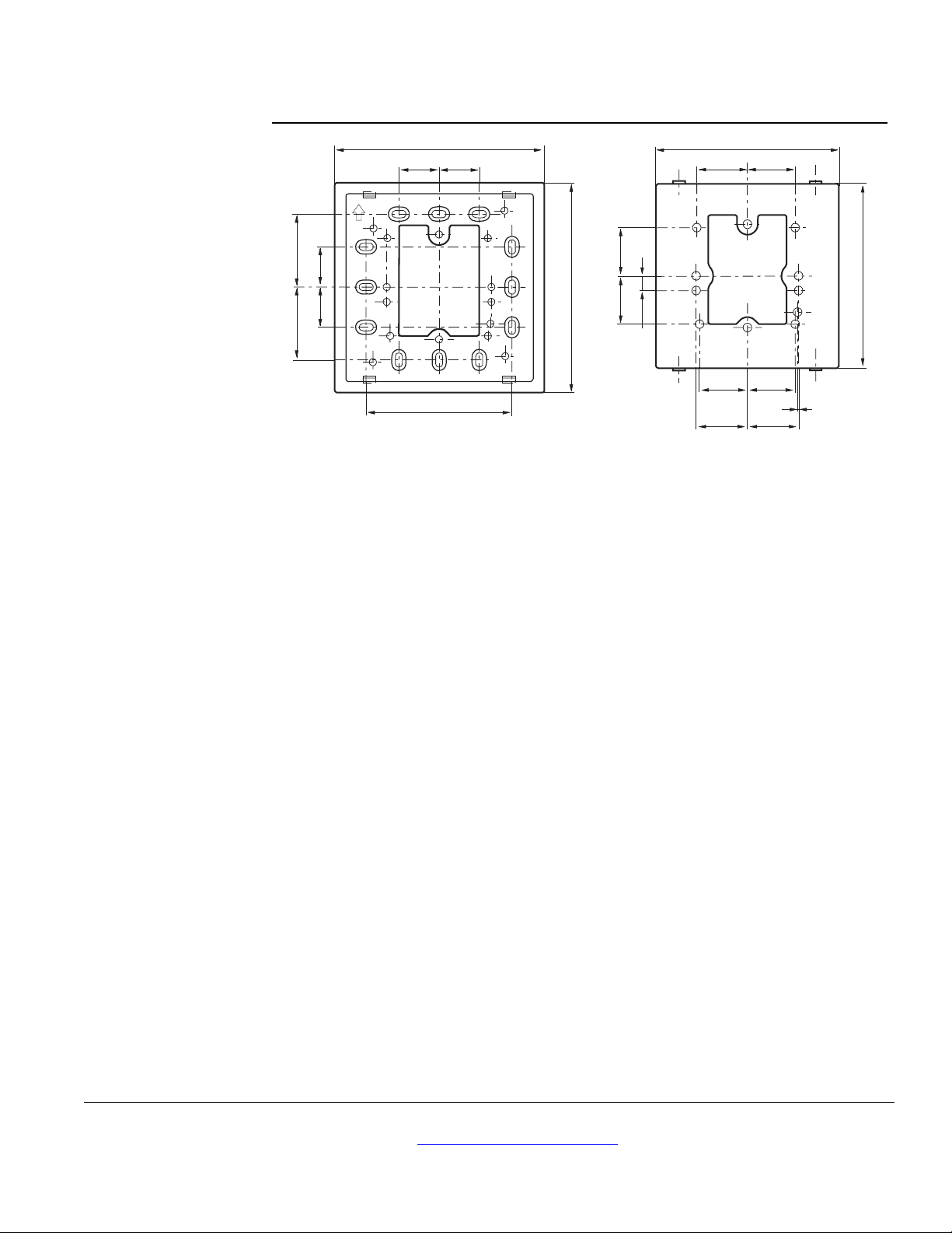
Figure 12. ARG70 Dimensions.
1.1(28)1.1(28)
TH0513R1
0.33(8.5)
4.21(107)
1.1(28)1.1(28)
1.18(30)1.18(30)
0.04(1)
Information in this publication is based on current specifications. The company reserves the right to make changes in specifications and models as
design improvements are introduced. Other product or company names mentioned herein may be the trademarks of their respective owners.
© 2006 Siemens Building Technologies, Inc.
Siemens Building Technologies, Inc.
1000 Deerfield Parkway
Buffalo Grove, IL 60089-4513
U.S.A.
Your feedback is important to us. If you have
comments about this document, please send
them to [email protected]
Document No. CM1N1958E-P25
Country of Origin: US
Page 11
 Loading...