

Page 1
TM
Flowrite
AP 599 Series
8-inch Pneumatic Valve Actuator
Technical Instructions
Document No. 155-161P25
AP 599-1
June 17, 2008
Description
Features
Application
Product Numbers
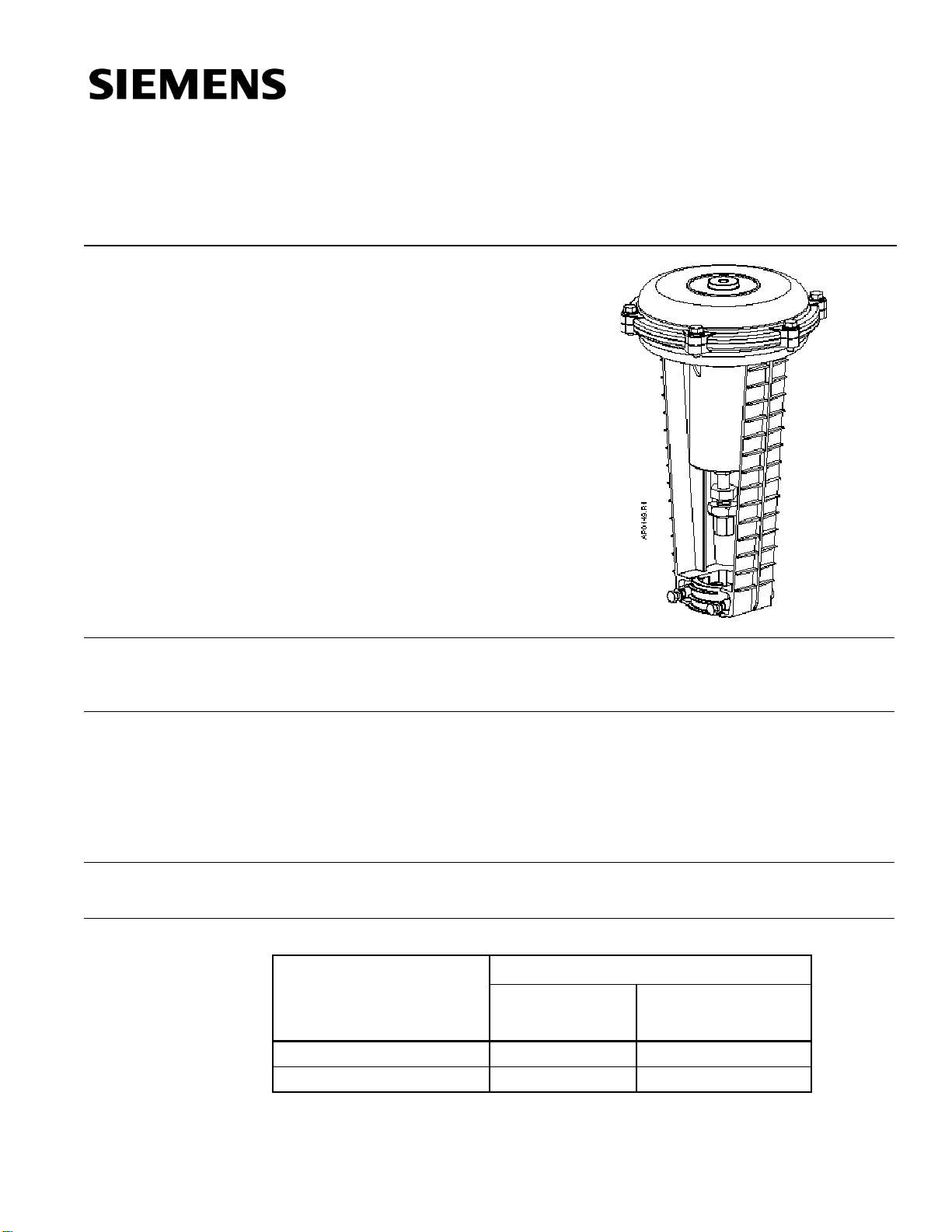
The Flowrite AP 599 Series 8-inch pneumatic valve actuator is designed for use with the
Flowrite VF 599 Series valves with a 3/4-inch (20 mm) stroke. This actuator is available
with two diaphragm options.
• Completely enclosed actuator housing protects the diaphragm, spring, and start
point adjuster.
• Positioning relay is available factory mounted or as an accessory.
• Start point of the actuator spring is adjustable. This allows the valve to be
sequenced.
• Easy installation.
These 8-inch actuators are designed to be used on Flowrite VF 599 Series valves in
liquid service and steam service applications.
Table 1.
Actuator Codes Product Numbers
8-inch Pneumatic
8-inch Pneumatic
599-01050 Normal Duty 277 283
599-01051 High Temperature 278 284
with Factory Mounted
Positioner
Siemens Building Technologies, Inc.
Page 2
Technical Instructions Flowrite™ 8-inch Pneumatic Valve Actuator
Document Number 155-161P25
June 17, 2008
Warning/Caution
Notations
Specifications
Operating
Temperatures
Operating
Miscellaneous
Accessories
WARNING
:
CAUTION:
Effective diaphragm area 28 inches2 (180 cm2)
Normal duty service – media temperatures Buna-N
25°F to 300°F (–4°C to 149°C)
High temperature service – media temperatures Silicone rubber
25°F to 366°F (–4°C to 186°C)
Ambient operating and storage temperature 35°F to 180°F (2°C to 85°C)
Nominal spring range
Fixed span
Normal duty service 5 psi (34 kPa)
High temperature service 10 psi (68 kPa)
Adjustable start point 3 to 10 psi (21 to 69 kPa)
Factory setting 3 to 8 psig (21 to 55 kPa) NO valves
10 to 15 psig (69 to 103 kPa) NC valves
Nominal stroke 3/4-inch (20 mm)
Maximum diaphragm pressure 35 psi (241 kPa)
Air Connection 1/8-inch NPT
Mounting location NEMA 1 (interior only)
Dimensions 14-1/8-in H x 8-3/4-in diameter
(359 mm H x 222 mm diameter)
Shipping weight 8.7 lbs. (4 kg)
Packing Heater Kit 599-00418
Positioning Relay and Mounting Kit 599-00426
Instructions for mounting are included with the accessory.
Spring Clamp (secures 1/4-inch O.D. polytubing to barb-fitting 531-833
at higher control pressures or elevated temperatures)
Personal injury/loss of life may occur if a
procedure is not performed as specified.
Equipment damage, or loss of data may
occur if the user does not follow a
procedure as specified.
Service Kits
Page 2 Siemens Building Technologies, Inc.
Diaphragm replacement kit (package of one)
Normal duty 599-01060
High temperature service 599-01061
Stem adapter kit for 8-inch Pneumatic Actuator 599-00435
Stem retainer kit 599-10048
Actuator Retainer Kit 599-00436
Page 3
Flowrite™ 8-inch Pneumatic Valve Actuator Technical Instructions
Document Number 155-161P25
June 17, 2008
Operation
Mounting and
Installation
The control air signal upon the diaphragm causes the valve to modulate whenever the
air pressure is within the spring range of the actuator. The actuator spring provides the
necessary force to hold the stem in the stem up (direct acting) position.
Allow 12 inches (300 mm) headroom and six inches (150 mm) on either side for
servicing the actuator.
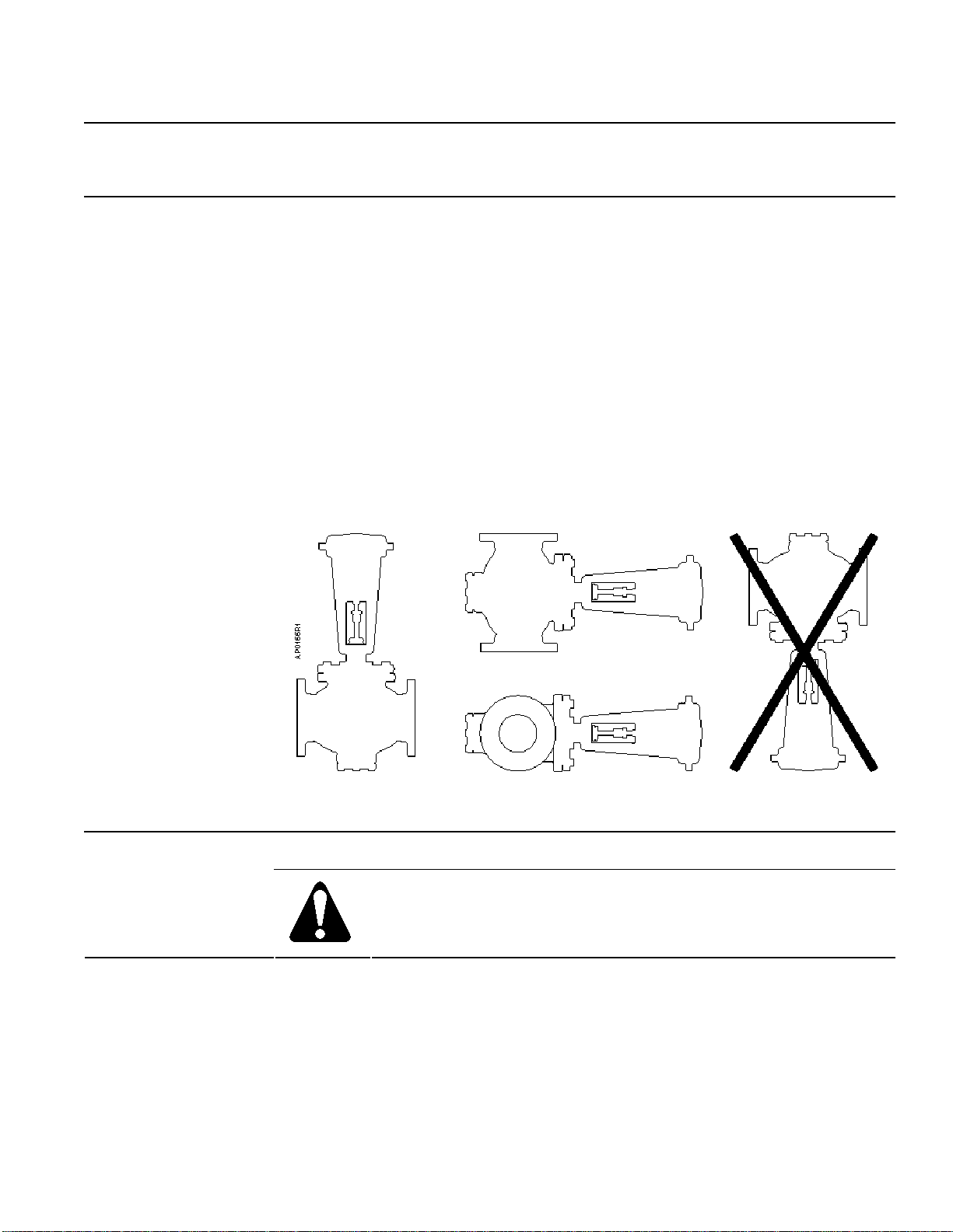
For best performance install the actuator vertically above the valve. The actuator may be
installed in any position between vertical and horizontal. Siemens Building Technologies
does not recommend installing the actuator below horizontal or up side down. See
Figure 1 for allowable mounting positions.
Complete instructions for field mounting the actuator are included with the actuator.
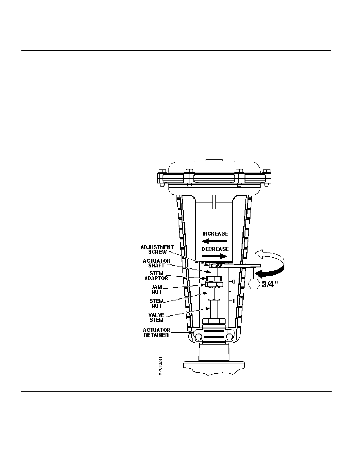
The top edge of the stem nut indicates the valve stem position. The “0” marking on the
actuator yoke indicates stem up position. The “1” mark indicates stem down position.
See Figure 2.
Figure 1. Acceptable Mounting Positions.
Service
Diaphragm
Replacement
Siemens Building Technologies, Inc. Page 3
Complete instructions are included in the diaphragm replacement kit.
WARNING:
Relieve spring tension before removing the actuator upper housing.
Page 4
Technical Instructions Flowrite™ 8-inch Pneumatic Valve Actuator
Document Number 155-161P25
June 17, 2008
Spring Adjustment
With the actuator in an upright position and the stem visible as shown in Figure 2, use a
3/4-inch (.75 mm) open end wrench to turn the adjustment screw.
• Normally Open Valves: To increase the start to close pressure, turn the adjustment
screw from right to left. To decrease, turn the adjustment screw from left to right.
• Normally Closed Valves: To increase the start to open pressure, turn the adjustment
screw from right to left. To decrease, turn the adjustment screw from left to right.
NOTE: As the line pressure differential across the valve increases, the spring span
decreases.
Figure 2. Spring Adjustment.
Page 4 Siemens Building Technologies, Inc.
Page 5
Flowrite™ 8-inch Pneumatic Valve Actuator Technical Instructions
Document Number 155-161P25
June 17, 2008
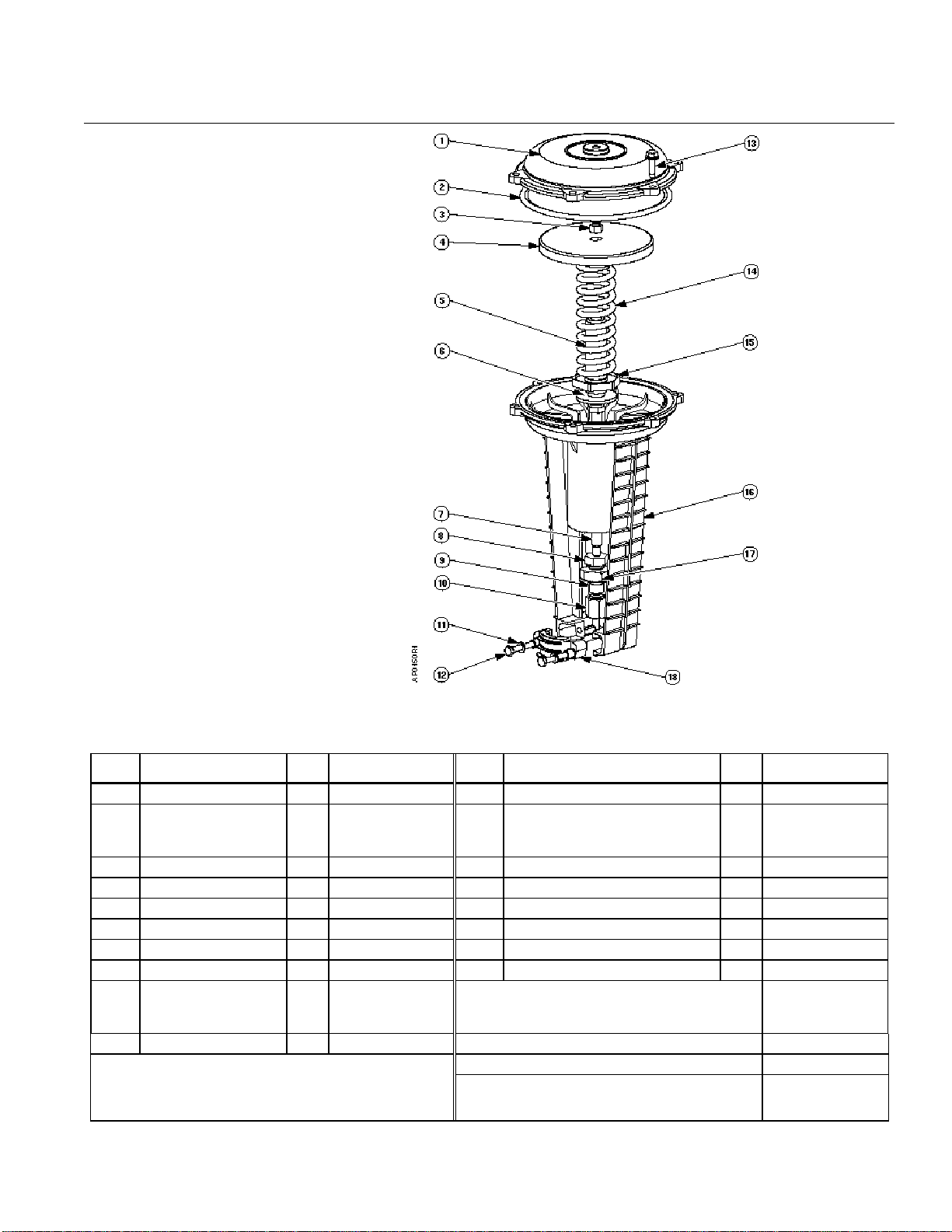
Parts of the 8-inch
Actuator
Figure 3. Flowrite AP 599 Series 8-inch Pneumatic Valve.
Item Description Q’ty Material Item Description Q’ty Material
1 Upper housing 1 Aluminum 11 1/4-20 external tooth lock washer 2 Plated Steel
Diaphragm
2
(Normal duty)
(High temperature)
3 3/8 x 24 hex nut 1 Plated steel 13 5/16-18 thread forming screws 6 Plated Steel
4 Piston plate 1 Aluminum 14 Spring 1 Chrome Van. Steel
5 Adjust. Screw Ass’y 1 Steel and bronze 15 Spring seat 1 Carbon Steel
6 Thrust washer 1 Carbon steel 16 Lower housing 1 Aluminum
7 Actuator shaft 1 Plated steel 17 Jam nut 1 Plated Steel
8 Stem adapter 1 Plated steel 18 Actuator retainer 1 Aluminum
Stem retainer clip 1 Stainless steel Diaphragm replacement kit
9
10 Stem nut 1 Stainless steel Stem retainer kit (One each of items 9 and 10) 599-10048
Siemens Building Technologies, Inc. Page 5
1
Neoprene
silicone
Stem adapter kit (items 8,9,10, and 17) 599-00435
Actuator retainer kit ( items 11, 12, and 18) 599-00436
1/4-20 hex head cap screw 2 Plated Steel
12
Normal duty
High temperature
Item 2
599-01060
599-01061
Page 6

Technical Instructions Flowrite™ 8-inch Pneumatic Valve Actuator
Document Number 155-161P25
June 17, 2008
Dimensions
8 3/4"
14 1/8"
AP0240R1
Figure 4. Dimensions in Inches (Millimeters).
Information in this publication is based on current specifications. The company reserves the right to make changes in specifications and models as
design improvements are introduced. Flowrite is a registered trademark of Siemens Building Technologies, Inc. Products or company names
mentioned herein may be the trademarks of their respective owners.
© 2008 Siemens Building Technologies, Inc.
Siemens Building Technologies, Inc.
1000 Deerfield Parkway
Buffalo Grove, IL 60089-4513
U.S.A.
Your feedback is important to us. If you have comments
about this document, please send them to
Document No. 155-161P25
Country of Origin: US
Page 6
 Loading...