

Page 1
s
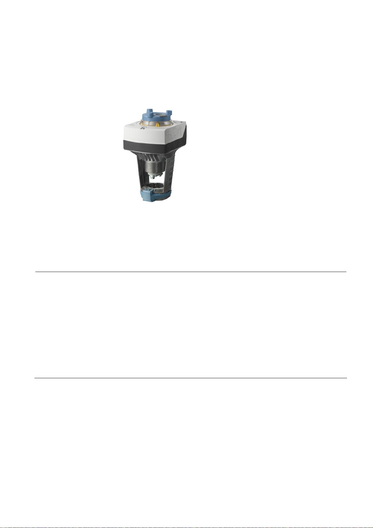
ACVATIX™
Electromotoric actuators for
SAY..P..
with a 15 mm stroke
A6V10628469
Use
valves
∂ SAY31P03 Operating voltage AC 230 V, 3-position control signal
∂ SAY61P03 Operating voltage AC/DC 24 V, control signal DC 0…10 V,
4…20 mA
∂ SAY81P03 Operating voltage AC/DC 24 V, 3-position control signal
∂ SAY61P03 Position feedback, override control,
choice of flow characteristic
∂ For direct mount ing on valves; no adjustments required
∂ Manual adjuster, position indicator and status indication per LED
∂ Optional functions with auxiliary switches,
function module
Electromotoric actuators for the operation of Siemens combi valves of type
VPI46.40F9.5Q and VPI46.50F12Q with 15 mm stroke as control valves in ventilation, air conditioning, and district heating systems.
A6V10628469_de--_c
2018-03-12
Building Technologies
Page 2
Type summary
Product no. Stock no. Stroke
SAY31P03
SAY61P03
SAY81P03
S55150A132
S55150A133
S55150A134
15 mm 200 N
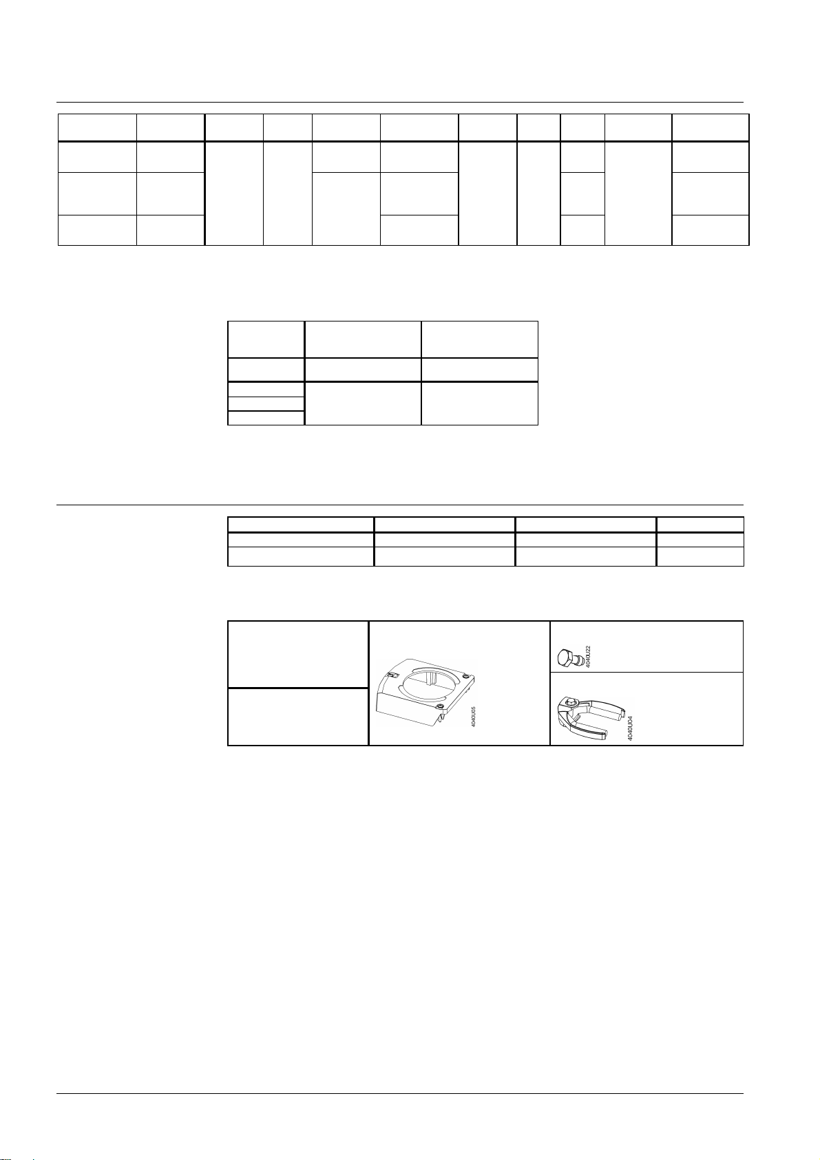
Electrical accessories
Mechanical Accessory
Ordering
Pos.
force
1)
Optional accessories: Auxiliary switch ASC10.51
2)
Positioning feedback, forced control, characteristic curve changeover
3)
Optional accessories: Auxiliary switch ASC10.51, s equence control, control action changeover
AZX61.1
Product no.
Stock no. S55845-Z103 S55845-Z107
SAY31P..
SAY61P..
SAY81P..
Operating
voltage
AC 230 V 3-position
AC/DC 24 V
Auxiliary switch
ASC10.51
Max. 2 Max. 1 AZX61.1
Positioning
signal
DC 0…10 V
DC 4…20 mA
0…1000 Ω
3-position
Function module
Spr. ret.
time
- 30 s
AZX61. 1
Pos.
time
LED
-
Ο
-
Manual
adjuster
Push and fix
Weather shield ASK39.1
Extra
functions
1)
2), 3)
1)
Example
Delivery
Spare parts
Product no. Stock no. Description Quantity
SAY81P03 S55150-A 134 Actuator 1
ASC10.51 S55845-Z103
Auxiliary switch
Actuators, valves and accessories are supplied in individual packs.
Housing cover Screw (valve stem c oupling)
Product nu mber /
Stock number
8000060843
U-brac ket
1
2 / 10
Siemens Electromotoric actuators for valves A6V10628469_de--_c
Building Technologies 2018-03-12
Page 3
Combinations
100
min
1)
Type Stock no. DN [mm] [l/h] [l/h] [kPa] Data shee t
VPI46. 40F 9.5Q S55264-V129 40
VPI46.50F12Q S55264-V130 50 1400 11500 36
Product docume nta tion
Notes
Engineering
SAY31P03 and
SAY81P03
SAY61P03
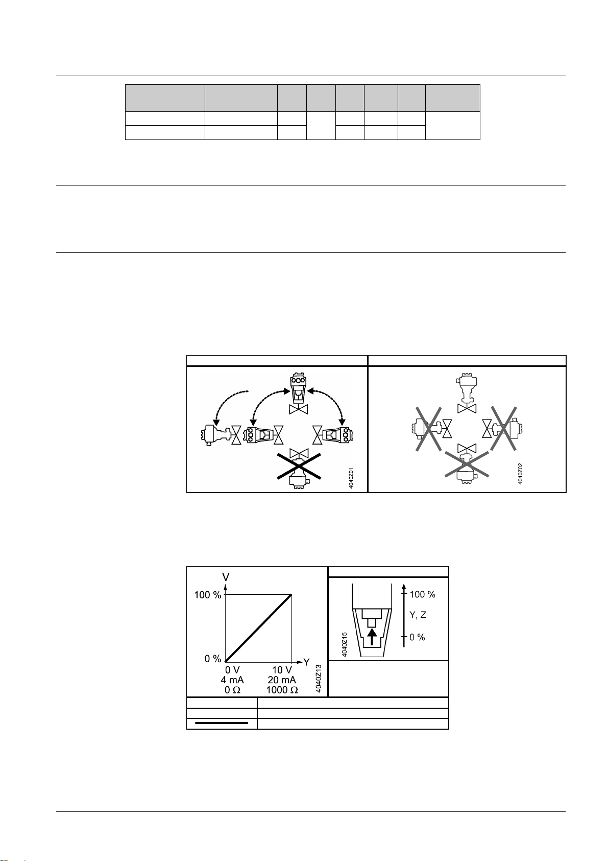
Mounting
Mounting positions
%
V
H
1370 9500 25
15
%
V
min
100
∆p
N4855
Detailed Informations about the New Generation actuators can be found in the Basic
documentation for actuators (P4040).
3-position actuators must have their own specific controller, refer to "Connection
Diagrams" (page 8).
Up to 10 actuators can drive in parallel on a controller output with a rating of 1 mA.
Modulating actuators have an input impedance of 100 kΩ.
Indoor use Outdoor use
Acting direction
Maintenance
1)
Only in connection wit h weather shield ASK39.1
With valves whose stem is retracted in the fully closed position, "direct acting" means
that the valve is fully closed (100 %) when positioning signal Y = 0 V and Z = 0 Ω respectively.
Direct acting
Pos. signal Y DC 0…10 V
Pos. signal Z 0...1000 Ω
Y, Z P ositioning signal
V Volumetric flow
Acting dir ection: direct
4...20 mA
The actuators are maintenance-free.
3 / 10
Siemens Electromotoric actuators for valves A6V10628469_de-- _c
Building Technologies 2018-03-12
Page 4

Warranty
The engineering data specified in chapter "Combinations" (page 3) are only
guaranteed in connection with the Siemens valves listed.
Note
Disposal
When using the actuators in connection with valves of other manufacture,
correct functioning must be ensured by the user, and Siemens will assume
no responsibility.
The device is considered electrical and electronic equipment for disposal in terms of the applicable European Directive and may not be
disposed of as domestic garbage.
∂ Dispose of the device through channels provided for this
purpose.
∂ Comply with all local and currently applicable laws and regu-
lations.
4 / 10
Siemens Electromotoric actuators for valves A6V10628469_de--_c
Building Technologies 2018-03-12
Page 5

Technical Data
1)
1)
2)
SAY..P
Power supply Operating voltage
Frequenc y 45…65Hz
External supply line protection (EU)
Power consumption at 50 Hz
SAY31P03 Stem retracts / extends 6 VA / 3.5 W
SAY61P03 Stem retracts / extends 8 VA / 3.75 W
SAY81P03 Stem retracts / extends 5 VA / 3.75 W
Function data Positioning times (with the specified nominal stroke)
The positioning time can vary, depending on the type
of valve -> refer chapter "Type summary" (page 2)
Positioning force 200 N
Nominal stroke 15 mm
Permissible medium temperature (valve fitted) 1…120 °C
Signal inputs Positioning signal ”Y” SAY31P03, SAY81P03 3-position
SAY61P03 (DC 0...10 V) Current draw ≤ 0.1 mA
SAY61P03 (DC 4...20 mA) Current draw DC 4...20 mA ± 1%
Parallel operation SAY61P03 ≤ 10 (depending on c ontroler output)
Forced control Positioning signal ”Z” SAY61P03 R = 0…1000 Ω, G, G0
Position feedback Position f eedback U SAY61P03 DC 0...10 V
Connecting cable Wire cross-sectional areas
Cab le entries SAY..P..
SAY31P03 AC 230 V ±15%
SAY61P03 AC 24 V ± 20% / DC 24 V + 20% / -15%(SE LV)
SAY81P03 AC 24 V ±20% / DC 24 V + 20 % / -15%(SELV)
∂ Fuse slow 6…10 A
∂ Circuit breaker max. 13 A, Characteristic B, C,
D according to EN 60898
∂ Power s ource with curr ent limitation of
max. 10 A
SAY31P03, SAY61P03, SAY81P03 30 s
SAY31P.. Voltage AC 230 V ±15%
SAY81P.. Voltage AC 24 V ± 20 % / DC 24 V + 20 % / -15%
Input impedance ≥ 100 kΩ
Input impedance ≤ 500 Ω
R = 0…1000 Ω Stroke proportional to R
Z connected to G Max. stroke 100%
Z connected to G0 Min. stroke 0%
Voltage Max. AC 24 V ± 20%
Max. DC 24 V + 20% / -15%
Current draw ≤ 0.1 mA
Load impedance > 10 kΩ res.
Load Max. 1 mA
0.75…1.5 mm2, AWG 20…16
EU: 2 entries ⊕ 20.5 mm (f or M20)
1 entry ⊕ 25.5 mm (for M25)
1)
Observe acting direction of DIL switches
2)
AWG = Americ an wire gauge
5 / 10
Siemens Electromotoric actuators for valves A6V10628469_de-- _c
Building Technologies 2018-03-12
Page 6

Degree of protection Protection degree of housing from vertic al to
1)
2)
2)
3)
IP54 as per EN 60529
horizontal
Protection class As per EN 60730-1
Actuators SAY31P03Y AC 230 V II
Actuators SAY61P03Y AC / DC 24 V III
Actuators SAY81P03Y AC / DC 24 V III
Environmental conditions Operation IEC 60721-3-3
Climatic conditions Class 3K5
Mounting location Indoors (weather-protected)
Temperature General 5…55 °C
Humidity (noncondensing) 5…95% r.h.
Transport IEC 60721-3-2
Climatic conditions Class 2K3
Temperature -25…70 °C
Humidity <95% r.h.
Storage
Climatic conditions
IEC 60721-3-1
Class 1K3
Temperature -15…55 °C
Humidity 5…95% r.h.
Max. media temperatur when mounted on valve 120 °C
Directives and Standards Product standard EN 60730-x
Electromagnetic compatibility (Applic ation) For residential, commercial and industrial
environments
EU Conformity (CE) A5W00000333
RCM Conf ormit y AC 230VA5W00000334
EAC Conf ormity Eurasia Conformity for all SA Y..P..
UL, cUL AC 230V-
AC / DC 24VUL 873 http://ul.com/database
Environmental compatibility The product environmental declaration
7173310559Ben2) contains data on environmen-
tally compatible product design and ass essments
(RoHS complianc e, materials composition, pack-
aging, environmental benefit, dispos al).
Dimensions See "Dimensions" (page 9)
Accessories
Auxiliary switch ASC10.51 Switching capacity
External supply line protection
US installation, UL & cUL
1)
Also with weather shield ASK39.1
2)
The documents can be downloaded from http://siemens.com/bt/download.
AC 24…230 V, 6 (2) A, floating
See section power supply
AC 24 V class 2, 5 A general purpose
3)
UL recognized component
6 / 10
Siemens Electromotoric actuators for valves A6V10628469_de--_c
Building Technologies 2018-03-12
Page 7

Connection Diagrams
Internal Diagrams
SAY31P03
SAY61P03
SAY81P03
Accessor ies
1x ASC10.51
Accessor i es
1x ASC10.51
Accessor i es
1x ASC10.51
Connection terminals
SAY31P03
SAY61P03
SAY81P03
AC 230 V, 3-position
Sytem neutral (SN)
Positioning signal (actuator’s stem retracts)
Positioning signal (actuator’s stem extends)
AC/DC 24 V, DC 0…10 V / 4…20 mA / 0…1000 Ω
Sytem neutral (SN)
Sytem potential (S P)
Positioning signal for DC 0…10 V / 4…20 mA
Measuring neutral
Position f eedback DC 0...10 V
Positioning signal forced c ontrol
AC/DC 24 V, 3-position
Sytem potential (S P)
Positioning signal (actuator’s stem retracts)
Positioning signal (actuator’s stem extends)
7 / 10
Siemens Electromotoric actuators for valves A6V10628469_de-- _c
Building Technologies 2018-03-12
Page 8

Connection Diagrams
SAY31P03
SAY61P03
A Actuator
L Phase
N Neutral
N1 Controll er
Y1, Y2 Positioning signals
A Actuator
F2 Frost protection thermostat; terminals:
1 – 2 frost hazard / sensor is interrupted (thermostat closes with frost)
1 – 3 normal operation
F3 Temperature detector
F4 Frost protection monitor with 0…1000 Ω signal output, does NOT support QAF21.. or QAF61..
M Measuring neutral
N1 C ontrol ler
SN S ystem neutral
SP System potential AC/DC 24 V
U Position f eedback
Y Position signal
Z Positioning signal forc ed control
SAY81P03
A Actuator
N1 controller
SN System neutral
SP System potential AC/DC 24 V
Y1, Y2 Positioning signals
8 / 10
Siemens Electromotoric actuators for valves A6V10628469_de--_c
Building Technologies 2018-03-12
Page 9

Dimensions
Revision numbers
Type
SAY..P..
With ASK39.1
Dimensions in mm
Product no. Valid from rev. no.
SAY31P03 ..A
SAY61P03 ..A
SAY81P03 ..A
A B C C1 C2 D E ► ►►
242 124 150 68 82 80 100 100 200
+25 154 300 200 100 - - - -
1.780
2.010
9 / 10
Siemens Electromotoric actuators for valves A6V10628469_de-- _c
Building Technologies 2018-03-12
Page 10

Issued by
www.siemens.com/buildingtechnologies
Siemens Switzerland Ltd
Building Technologies Division
International Headquarters
Theilerstrasse 1a
6300 Zug
Switzerland
Tel. +41 58-724 24 24
10 / 10
Siemens Electromotoric actuators for valves A6V10628469_de--_c
Building Technologies 2018-03-12
© Siemens Switzerland Ltd, 2015
Technical specific ations and availability subject to change without notice.
 Loading...