

Page 1

ACUSON S1000
ACUSON S2000
ACUSON S3000
Diagnostic Ultrasound System
Instructions for Use
Siemens Medical Solutions USA, Inc. 11286694-ABS-001-01-01
Page 2

siemens.com/healthcare
ACUSON S1000
ACUSON S2000
ACUSON S3000
Product Version VE10
©2008-2017 Siemens Medical Solutions USA, Inc.
All Rights Reserved.
February 2017
3-Scape, AcuNav, ACUSON, ACUSON AcuNav,
ACUSON S1000, ACUSON S2000, ACUSON S3000,
ACUSON S Family, Advanced fourSight,
Advanced SieClear, Axius, Cadence, Clarify,
Color SieScape, Contrast Dynamics, DTI, DTO,
Dynamic TCE, ElastoGrip, ErgoDynamic, eSieCalcs,
eSieCrypt, eSieFusion, eSieImage, eSieLink,
eSieScan, eSie Touch, Evolve Package, fourSight,
HELX, microCase, Multi-D, MultiHertz, SieClear,
Siemens Remote Service, SieScape, SpaceTime,
SuppleFlex, SwiftLink, TCE, TEQ, Vector, Velocity
Vector Imaging, and Virtual Touch are trademarks of
Siemens Medical Solutions USA, Inc.
syngo is a trademark of Siemens Healthcare GmbH.
All other product names are references to third-party
products and are trademarks of their respective
companies. Siemens includes references to
third-party products in the user documentation for
informational purposes only. Siemens does not
endorse third-party products referenced in the user
documentation. Siemens does not assume
responsibility for the performance of third-party
products.
Siemens reserves the right to change its products and
services at any time. In addition, this publication is
subject to change without notice.
CE Declaration
This product is provided with a CE marking in
accordance with the regulations stated in Council
Directive 93/42/EEC of June 14, 1993 concerning
Medical Devices. The CE marking only applies to
medical devices that have been put on the market
according to the above referenced Council Directive.
Unauthorized changes to this product are not covered
by the CE marking and the related Declaration of
Conformity.
EU Authorized Representative
Siemens Healthcare GmbH
Henkestr. 127
91052 Erlangen
Germany
Legal Manufacturer
Siemens Medical Solutions USA, Inc.
Ultrasound
685 East Middlefield Road
Mountain View, CA 94043
U.S.A.
Phone: +1-888-826-9702
Siemens Healthcare Headquarters
Siemens Healthcare GmbH
Henkestr. 127
91052 Erlangen
Germany
Phone: +49 9131 84-0
siemens.com/healthcare
Page 3

Contents
Chapter 1
Introduction
Chapter 2
Safety and Care
Chapter 4
Examination Fundamentals
Chapter 6
Transesophageal Transducer
Chapter 7
Specialty Transducers
Chapter 8
Physiologic Function
Chapter 9
eSieFusion Imaging
Chapter 10
Virtual Touch Applications
General overview of the diagnostic ultrasound imaging system.
Detailed information on system safety and how to care for and maintain the
system, transducers, and transducer accessories.
Chapter 3 System Setup
Detailed descriptions of how to transport, set up, and prepare the system for use,
including transducer connection and system startup procedures.
Information on starting an examination, including instructions for entering and
editing patient data and selecting an exam type, imaging mode, and transducer.
Chapter 5 Transducer Accessories and Biopsy
Attachment procedures for transducer accessories and an explanation of the
biopsy (puncture) function, including a procedure for needle path verification.
Description of the transesophageal transducer, including cleaning and care
information for the transducer.
Description of the following specialty transducers:
9EVF4
Explanation of the Physiologic function.
Explanation of eSieFusion imaging for viewing real-time ultrasound images aligned
with reference data acquired using another imaging modality. Includes procedures
for setting up the tracking system for eSieFusion imaging and procedures for
cleaning, disinfecting, and care of the tracking system.
Explanation of the following feature and options:
Virtual Touch imaging
Virtual Touch quantification
Virtual Touch IQ
Instructions for Use i
Page 4

Appendix A
Technical Description
Technical description of the ultrasound system.
Appendix B
Control Panel and Touch Screen
Appendix C
Control Panel
Appendix D
On-screen Controls
Appendix F
Acoustic Output Reference
Description of the controls on the control panel including the special keys on the
alphanumeric keyboards.
See also: An overview and example of the control panel is located in Chapter 1 of
this manual.
(For systems without a touch screen)
Explanation of all controls and keys on the control panel, alphanumeric keyboard,
and optional footswitch.
Explanation of the on-screen controls for imaging, review, measurements, and
patient data management.
Appendix E Advanced Feature Controls
Explanation of the on-screen controls for advanced imaging features and clinical
application programs.
Acoustic output reporting tables.
Note: Not all features and options described in this publication are available to all users. Please
check with your Siemens representative to determine the current availability of features and options.
ii Instructions for Use
Page 5

About the User and Reference Manuals
Acoustic output data
Manufacturer's Declaration*
The user and reference manuals contain descriptions for the following ultrasound systems:
ACUSON S1000 diagnostic ultrasound system
ACUSON S2000 diagnostic ultrasound system
ACUSON S3000 diagnostic ultrasound system
Features and options unique to an ultrasound system are identified in Chapter 1 and
Appendix A of the Instructions for Use.
The user and reference manuals consist of the following publications.
Publication Includes
Instructions for Use Conventions and typographical conventions used in the manuals
Intended Audience
Technical description of the ultrasound system
Safety and care information for the system and compatible transducers
Procedures for system setup, examination fundamentals, and the biopsy function
Procedures and descriptions of specialty transducers, the physiologic function, and
the following imaging features:
– eSieFusion imaging
– Virtual Touch applications
Descriptions of system controls
Features and Applications
Reference*
System Reference* Description of customizable system settings
Electromagnetic Emissions
and Immunity: Guidance and
Descriptions of image acquisition and optimization, including optional imaging
features
General and exam-specific measurements and calculations
Data management
Explanation of the clinical software programs for use on the ultrasound system
Information about DICOM connectivity, network capabilities, and external devices
Clinical references
Information regarding the electromagnetic compatibility (EMC) testing of this
system
*Languages supported by the user interface include a translation of this publication.
Instructions for Use iii
Page 6

Conventions
Take a moment to familiarize yourself with these conventions.
The user and reference manuals include procedures and descriptions for ultrasound systems
with and without a touch screen. Except where noted in the manuals, descriptions apply to both
systems.
The following bullet symbols indicate procedures or descriptions for systems with and without a
touch screen:
● This bullet symbol indicates a procedure specific to systems with a touch screen.
○ This bullet symbol indicates a procedure specific to systems without a touch screen.
This bullet symbol indicates a procedure or description for systems with and without a
touch screen.
– This bullet symbol indicates a procedure or description for systems with and without a
touch screen.
Except where noted in the manuals, numbered steps apply to both systems.
Warnings, Cautions, and
Notes
WARNING: Warnings are intended to alert you to the importance of following the
correct operating procedures where risk of injury to the patient or system user
exists.
Caution: Cautions are intended to alert you to the importance of following
correct operating procedures to prevent the risk of damage to the system.
Note: Notes contain information concerning the proper use of the system and/or
correct execution of a procedure.
Cross-References Examples:
See also: Biohazards, Safety and Care, Chapter 2, Instructions for Use
See also: Documentation Devices, Chapter 2, System Reference
See also: Alphanumeric Keyboard, p. 26
Customizable System
Settings
System settings available for customization are depicted as shown.
Example:
Use the system configuration menu to customize the registration form.
System Config > Patient Registration
iv Instructions for Use
Page 7
Examples of Interacting with the Control Panel
Example
Convention
Convention
The following conventions are used in this manual to provide you with a description of how to
identify and use the controls and keys located on the control panel, including the alphanumeric
keyboard.
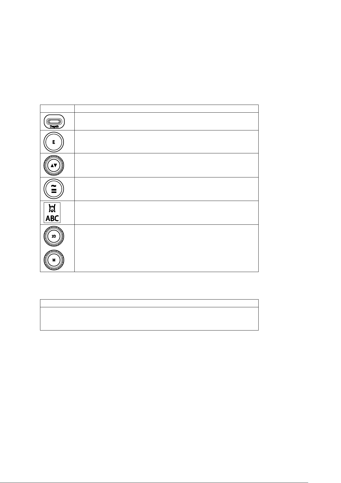
Push Controls, Press Controls, and Press or Rotate Controls
The labels on the control panel are depicted in this manual with text in upper case, boldface
type, as shown below.
Push DEPTH.
Press E to access the advanced imaging features.
Rotate the FORWARD/BACKWARD control to skip the current view in a protocol.
Press TEQ to activate or deactivate tissue equalization optimization.
To insert a body marker, press ANNOTATION and then select the required body
marker.
Rotate 2D to adjust the 2D gain.
Press M to activate the M cursor (line) on the 2D image.
Keys on the Alphanumeric Keyboard
The labels on the alphanumeric keyboard are depicted in this manual with text in boldface type,
as shown below.
Press Delete.
Press Help on the keyboard.
○ For systems without a touch screen, press F1.
Instructions for Use v
Page 8
Touch Screen Controls
Example
Convention
Example
Convention
Example
Convention
THI
Resize Full
The six controls directly below the touch screen are not labeled on the control panel. In this
manual, you can identify the function assigned to the control by the text in boldface type within
brackets, as shown below.
Press or rotate [EI Color] to select a color map.
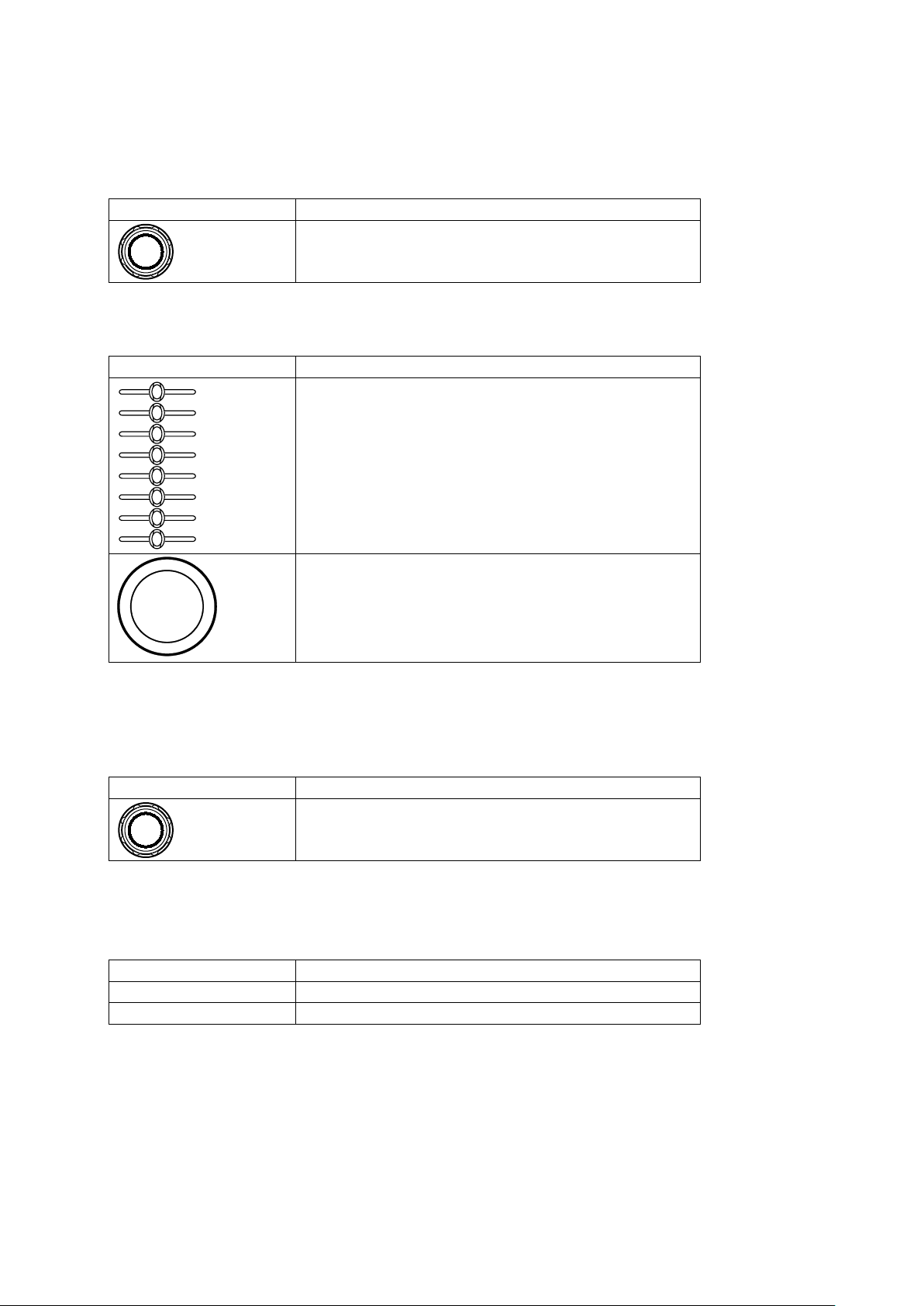
Other Controls
These controls do not have labels on the control panel. In this manual, you can identify the
function assigned to the control with descriptive text.
Slide the DGC sliders to adjust the depth gain compensation.
Roll the trackball to adjust the size of the field of view.
LED Controls
(For systems without a touch screen)
The six controls directly below the LED panel are not labelled on the control panel. In this
manual, you can identify the function assigned to the control by the text in boldface type within
brackets, as shown below.
Example Convention
Press or rotate [EI Color] to select a color map.
Soft Key Controls and Scroll Wheel
(For systems without a touch screen)
Soft key controls are located above the trackball with corresponding selections on the image
screen. In this manual, the on-screen labels are depicted with boldface type, as shown below.
Soft keys Press the
Scroll wheel Rotate the scroll wheel to select
soft key.
.
vi Instructions for Use
Page 9

Examples of Interacting with On-screen Objects
Example
Convention
Example
EI Color
Term
Description
Also, the action of tapping the touch screen.
quickly.
In this manual, the following conventions are used to provide you with a description of how to
identify and use menu selections and other software selections, including on-screen icons and
objects.
Toolbar Controls
Controls located on the toolbar are indicated by boldface type, as shown below.
Click Patient Registration on the toolbar.
Touch Screen Controls
Except for the labels on the lowest row, the labels on the touch screen are depicted in this
manual with text in boldface type, as shown below.
In this manual, procedures describe how to interact with objects on the touch screen.
Example Convention
TEQ Set Select TEQ Set.
---
The labels on the lowest row of the touch screen are depicted in this manual with text in
boldface type within brackets, as shown below. Press or rotate the control directly below the
label to activate the function assigned to the control.
To change the orientation of the transducer marker, drag the dot around the circle
on the touch screen.
Press or rotate [
] to select a color map.
Procedures
In this manual, procedures include the following conventions to describe user actions.
Note: Press POINTER to display the cursor on the image screen, if necessary.
Press The action of pressing a control on the control panel.
Rotate The action of rotating a control on the control panel.
Select
Click
Double-click
Drag
The action of highlighting an on-screen object, making a selection from a list, or
enabling an on-screen selection.
The action of rolling the trackball to position the pointer on an on-screen
selection in a list or menu and then pressing the left or right key on either side
of the trackball.
The action of rolling the trackball to position the pointer on an on-screen control or
object and then either pressing the left or right key on either side of the trackball.
The action of pressing the left or right key on either side of the trackball twice
The action of rolling the trackball to position the pointer on an on-screen object
and then pressing and holding the left key next to the trackball to move the
object around the screen.
The action of using your finger to touch and position or resize an object on the
touch screen.
Instructions for Use vii
Page 10

Intended Audience
User
Interaction with Ultrasound Equipment
Expected Experience and Other Characteristics
care subjects
The intended audience for the user and reference manuals includes the following users.
Sonographer
Cardiologist
Maternal-fetal
Medicine
Obstetrician/
Perinatologist
Radiologist
and Internist
System
Administrator
and Customer
Service
Engineer
Acquires diagnostic views of anatomy,
blood flow, and related pathology
Performs measurements and analysis of
the acquired images
Prepares exam data for review and
interpretation by a qualified physician
Performs invasive and non-invasive
ultrasound exams
Interprets exam data, including
echocardiography exam data
Writes and assembles exam findings in
a report
Performs ultrasound exams
Interprets exam data
Writes and assembles exam findings in
a report
Performs ultrasound exams
Interprets exam data
Writes and assembles exam findings in
a report
Configures the ultrasound system for
use in a networked environment
Ranges from novices (for example, students) to
advanced practitioners with certification in multiple
subspecialties
Educated in anatomy, physiology, patient care, and
identification of pathology in ultrasound images
Many sonographers have a Bachelor's degree;
some have advanced degrees in related health
Medical doctor
Expert in diagnostic imaging, including computed
tomography (CT), magnetic resonance imaging
(MRI), X-ray, ultrasound, and nuclear medicine
Advanced training in imaging physics with typically
four to six years of post-doctoral training in the field
of cardiology
Medical doctor
Manages high-risk obstetrical patients for the safe
and successful delivery of the fetus
Skilled in interpreting ultrasound exam data
Medical doctors
Expert in diagnostic imaging, including CT, MRI, X-
ray, ultrasound, and nuclear medicine
Advanced training in imaging physics with typically
two to six years of post-doctoral training in the field
of radiology
A System Administrator is an individual within your
organization who is designated to set up system
parameters to connect the ultrasound system or
workstation to a picture archiving and
communication system (PACS).
Customer Service Engineers are Siemens
representatives who configure the ultrasound
system or workstation during software installation
and support troubleshooting activities.
viii Instructions for Use
Page 11

1 Introduction
System Overview ................................................................................................ 3
System Review .............................................................................................. 4
Control Panel ...................................................................................................... 7
Example of Control Panel .............................................................................. 7
Intended Use ....................................................................................................... 9
Contraindications ........................................................................................... 9
ACUSON S1000 Ultrasound System ............................................................. 9
Indications for Use Statement .............................................................. 10
ACUSON S2000 Ultrasound System ........................................................... 11
Indications for Use Statement .............................................................. 11
ACUSON S3000 Ultrasound System ........................................................... 12
Indications for Use Statement .............................................................. 12
Transducers and Intended Applications ...................................................... 13
Image Screen Layout ........................................................................................ 19
Screen Saver ............................................................................................... 19
Sample Image Screens ............................................................................... 20
Instructions for Use 1 - 1
Page 12

1 Introduction
1 - 2 Instructions for Use
Page 13

1 Introduction
System Overview
The ACUSON S Family ultrasound systems are designed to streamline clinical workflow from
image acquisition to archival in a diagnostic setting for general imaging, vascular, and cardiac
applications. The system supports software-based applications, exam-specific imaging presets,
measurements, body markers, annotations, patient reports, and system diagnostics. The
system design is based upon image quality, knowledge-based workflow, adaptive ergonomics,
and innovative applications.
Operating modes for the system include:
2D-mode
2D-mode with THI (Tissue Harmonic Imaging)
Dual mode
2D/M-mode
M-mode with THI
M-mode with CDV
Pulsed Wave Doppler
Color Doppler Energy (CDE)
Color Doppler Velocity (CDV)
Steerable Continuous Wave Doppler
Auxiliary Continuous Wave Doppler
See also: Technical Description, Appendix A, Instructions for Use
Instructions for Use 1 - 3
Page 14
1 Introduction
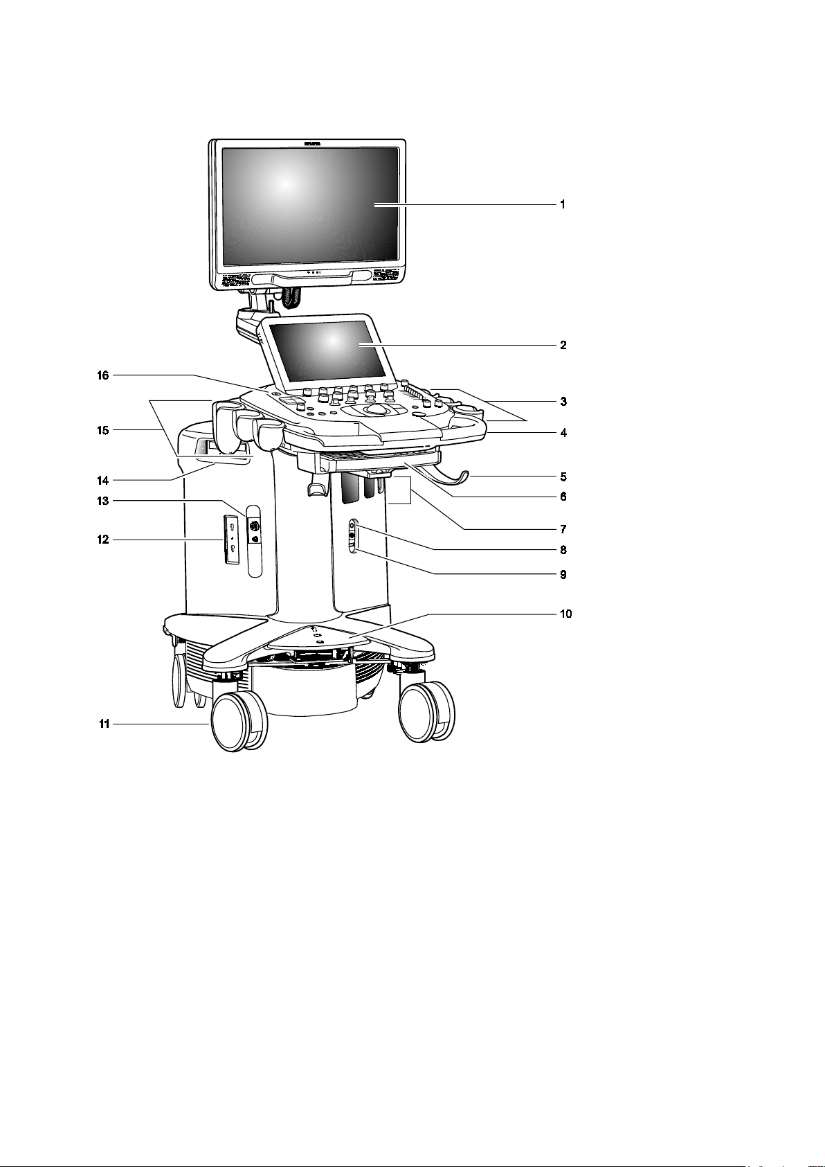
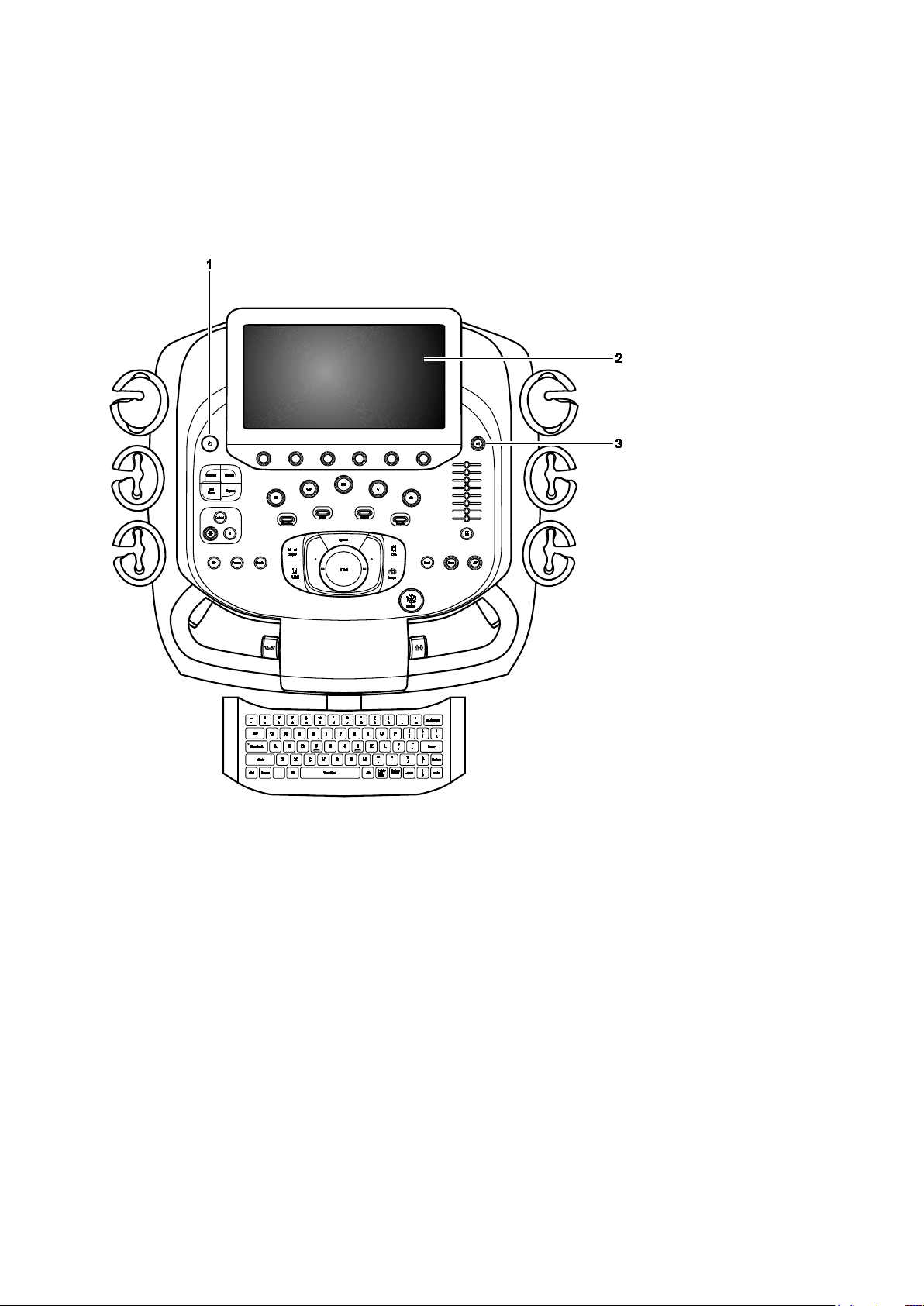
System Review
Example of the ultrasound system.
1 - 4 Instructions for Use
Page 15

1 Introduction
1 User-adjustable high-resolution flat panel monitor with two forward-facing speakers
2 Touch screen
For systems without a touch screen, this is the location of the alphanumeric keyboard
3 User-adjustable control panel (height and swivel)
4 Front handle
5 Cable hanger
6 Retractable alphanumeric keyboard (for systems with a touch screen)
7 Transducer ports
8 Auxiliary continuous wave Doppler transducer port
9 Footswitch connector
10 Central brakes
11 Front swivel wheels
12 Parking port for transducers
13 Physio panel
14 CD/DVD-RW drive
15 Transducer and gel holders
16 Power ON/OFF
(Standby)
Instructions for Use 1 - 5
Page 16
1 Introduction
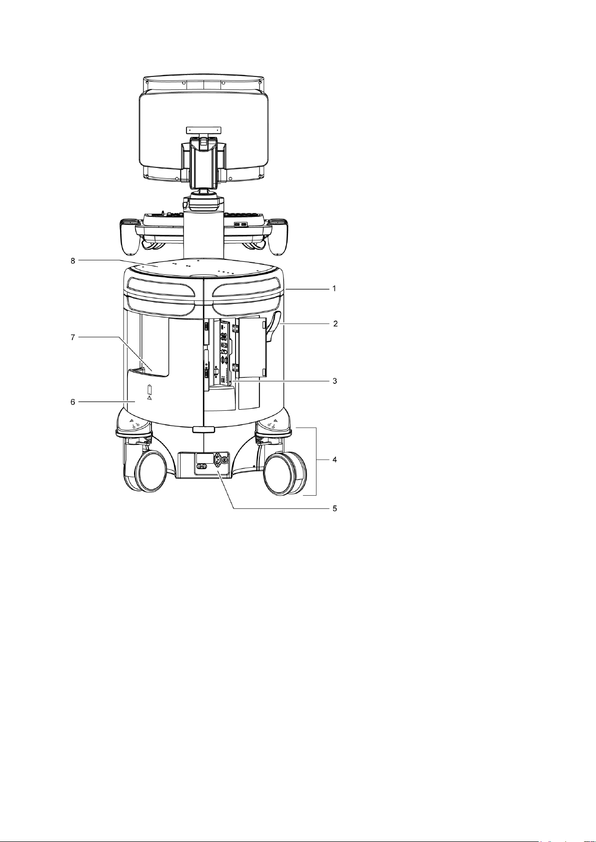
Example of the ultrasound system, back view.
1 Rear handle
2 Cable hanger
3 Input/output panel with audio and video connections
4 Rear swivel wheel with brake
5 AC tray panel
6 Back panel
7 Storage bin
8 Shelf
1 - 6 Instructions for Use
Page 17
1 Introduction
Control Panel
The ultrasound imaging system has a combination of keys, rotary knobs, push and rotate
controls, and toggle controls. A trackball provides access to on-screen objects. The keys and
controls are logically arranged to require a minimum number of hand and eye movements.
Example of Control Panel
Example of the control panel and touch screen on the ultrasound system.
1 Power on/off
For systems without a touch screen, the power on/off control, the backlighting and task lighting control,
the volume control and microphone control, and transmit power control are located above the
alphanumeric keyboard.
Instructions for Use 1 - 7
Page 18

1 Introduction
2 Touch screen with selections for each operating mode's optimization parameters and functions,
measurement labels and tools, review selections, and selections for exam types and transducers. You
can tap the touch screen to make a selection.
Six controls are located on the control panel with corresponding selections on the touch screen. Press,
rotate, or press and then rotate these controls to select a setting.
For systems without a touch screen, six controls on the control panel have corresponding selections on
the LED panel. Additionally, the image menu includes the mode-specific optimization parameters and
functions, measurement labels and tools, review selections, and the access to exam types and
transducers.
For systems without a touch screen, this location includes soft key selections available for the active
mode or function. Soft key selections correspond to the controls and scroll wheel on the control panel
directly above the trackball.
3 Doppler audio volume control
For systems without a touch screen, this control includes a microphone and is located above the
alphanumeric keyboard.
1 - 8 Instructions for Use
Page 19

1 Introduction
Intended Use
WARNING: The analysis of results from an ultrasound examination requires that you are trained
in the interpretation of diagnostic ultrasound studies and are qualified to make clinical
diagnoses.
Caution: In the United States of America, federal law restricts this device to sale or use by, or
on the order of, a physician.
Caution: Ultrasound is used as an imaging aid, but may have further restrictions specific to
in-vitro fertilization (IVF), chorionic villus sampling (CVS), and percutaneous umbilical cord blood
sampling (PUBS) procedures. Observe local laws and regulations.
Contraindications
The ultrasound system is not intended for ophthalmic use or any ophthalmic application causing
the acoustic beam to pass through the eye.
ACUSON S1000 Ultrasound System
The ACUSON S1000 ultrasound system supports the following applications:
Abdominal (Renal)
Obstetrics (Fetal Echo)
Gynecology
Small Parts (Breast, Testicle, Thyroid)
Musculoskeletal
Pediatric (Abdomen, Infant Hip, and Neonatal Cephalic)
Cardiac
Vascular (Arterial and Venous)
Digital
Urology (Penile, Pelvis, Prostate)
Instructions for Use 1 - 9
Page 20

1 Introduction
adult and pediatric patients.
Indications for Use Statement
Product Indications for Use Statement
ACUSON S1000
Ultrasound System
syngo Arterial Health
Package (AHP)
ACUSON AcuNav
Ultrasound Catheter
The S1000™ ultrasound imaging systems are intended for the following applications: Fetal,
Abdominal, Intraoperative, Pediatric, Small Parts, Transcranial, OB/GYN (useful for
visualization of the ovaries, follicles, uterus, and other pelvic structures), Cardiac, Pelvic,
Neonatal/Adult Cephalic, Vascular, Musculoskeletal, Superficial Musculoskeletal, and
Peripheral Vascular applications.
The system also provides the ability to measure anatomical structures {fetal, abdominal,
intraoperative, pediatric, small organ, neonatal cephalic, adult cephalic, cardiac, transesophageal, transrectal, transvaginal, peripheral vessel, musculo-skeletal (conventional),
musculo-skeletal (superficial) and neonatal cardiac} and calculation packages that provide
information to the clinician that may be used adjunctively with other medical data obtained
by a physician for clinical diagnosis purposes.
The Arterial Health Package (AHP) software provides the physician with the capability to
measure Intima Media Thickness and the option to reference normative tables that have
been validated and published in peer-reviewed studies. The information is intended to
provide the physician with an easily understood tool for communicating with patients
regarding state of their cardiovascular system.
This feature should be utilized according to the "ASE Consensus Statement; Use of Carotid
Ultrasound to Identify Subclinical Vascular Disease and Evaluate Cardiovascular Disease
Risk: A Consensus Statement from the American Association of Echocardiography; Carotid
Intima-Media Thickness Task Force, Endorsed by the Society for Vascular Imaging."
The catheter is intended for intracardiac and intraluminal visualization of cardiac and great
vessel anatomy and physiology, as well as visualization of other devices in the heart of
1 - 10 Instructions for Use
Page 21

1 Introduction
Product
Indications for Use Statement
ACUSON S2000 Ultrasound System
The ACUSON S2000 ultrasound system supports the following applications:
Abdominal (Renal)
Obstetrics (Fetal Echo)
Gynecology
Small Parts (Breast, Testicle, Thyroid)
Musculoskeletal
Pediatric (Abdomen, Infant Hip, and Neonatal Cephalic)
Cardiac
Vascular (Arterial and Venous)
Digital
Urology (Penile, Pelvis, Prostate)
Indications for Use Statement
ACUSON S2000
Ultrasound System
syngo Arterial Health
Package (AHP)
ACUSON AcuNav
Ultrasound Catheter
The S2000™ ultrasound imaging systems are intended for the following applications: Fetal,
Abdominal, Intraoperative, Pediatric, Small Parts, Transcranial, OB/GYN (useful for
visualization of the ovaries, follicles, uterus, and other pelvic structures), Cardiac, Pelvic,
Neonatal/Adult Cephalic, Vascular, Musculoskeletal, Superficial Musculoskeletal, and
Peripheral Vascular applications.
The system also provides the ability to measure anatomical structures {fetal, abdominal,
intraoperative, pediatric, small organ, neonatal cephalic, adult cephalic, cardiac, transesophageal, transrectal, transvaginal, peripheral vessel, musculo-skeletal (conventional),
musculo-skeletal (superficial) and neonatal cardiac} and calculation packages that provide
information to the clinician that may be used adjunctively with other medical data obtained
by a physician for clinical diagnosis purposes.
The Arterial Health Package (AHP) software provides the physician with the capability to
measure Intima Media Thickness and the option to reference normative tables that have
been validated and published in peer-reviewed studies. The information is intended to
provide the physician with an easily understood tool for communicating with patients
regarding state of their cardiovascular system.
This feature should be utilized according to the "ASE Consensus Statement; Use of Carotid
Ultrasound to Identify Subclinical Vascular Disease and Evaluate Cardiovascular Disease
Risk: A Consensus Statement from the American Association of Echocardiography; Carotid
Intima-Media Thickness Task Force, Endorsed by the Society for Vascular Imaging."
The catheter is intended for intracardiac and intraluminal visualization of cardiac and great
vessel anatomy and physiology, as well as visualization of other devices in the heart of
adult and pediatric patients.
Instructions for Use 1 - 11
Page 22

1 Introduction
Product
Indications for Use Statement
ACUSON S3000 Ultrasound System
The ACUSON S3000 ultrasound system supports the following applications:
Abdominal (Renal)
Obstetrics (Fetal Echo)
Gynecology
Small Parts (Breast, Testicle, Thyroid)
Musculoskeletal
Pediatric (Abdomen, Infant Hip, and Neonatal Cephalic)
Cardiac
Vascular (Arterial and Venous)
Digital
Urology (Penile, Pelvis, Prostate)
Indications for Use Statement
ACUSON S3000
Ultrasound System
syngo Arterial Health
Package (AHP)
ACUSON AcuNav
Ultrasound Catheter
The S3000™ ultrasound imaging systems are intended for the following applications: Fetal,
Abdominal, Intraoperative, Pediatric, Small Parts, Transcranial, OB/GYN (useful for
visualization of the ovaries, follicles, uterus, and other pelvic structures), Cardiac, Pelvic,
Neonatal/Adult Cephalic, Vascular, Musculoskeletal, Superficial Musculoskeletal, and
Peripheral Vascular applications.
The system also provides the ability to measure anatomical structures {fetal, abdominal,
intraoperative, pediatric, small organ, neonatal cephalic, adult cephalic, cardiac, transesophageal, transrectal, transvaginal, peripheral vessel, musculo-skeletal (conventional),
musculo-skeletal (superficial) and neonatal cardiac} and calculation packages that provide
information to the clinician that may be used adjunctively with other medical data obtained
by a physician for clinical diagnosis purposes.
The Arterial Health Package (AHP) software provides the physician with the capability to
measure Intima Media Thickness and the option to reference normative tables that have
been validated and published in peer-reviewed studies. The information is intended to
provide the physician with an easily understood tool for communicating with patients
regarding state of their cardiovascular system.
This feature should be utilized according to the "ASE Consensus Statement; Use of Carotid
Ultrasound to Identify Subclinical Vascular Disease and Evaluate Cardiovascular Disease
Risk: A Consensus Statement from the American Association of Echocardiography; Carotid
Intima-Media Thickness Task Force, Endorsed by the Society for Vascular Imaging."
The catheter is intended for intracardiac and intraluminal visualization of cardiac and great
vessel anatomy and physiology, as well as visualization of other devices in the heart of
adult and pediatric patients.
1 - 12 Instructions for Use
Page 23
1 Introduction
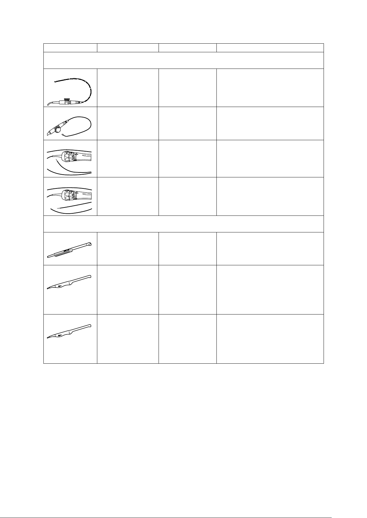
Transducer Name
Operating Frequency1
Modes of Operation2
Intended Applications
(Available on the ACUSON S1000 system, ACUSON S2000 system, and ACUSON S3000 system)
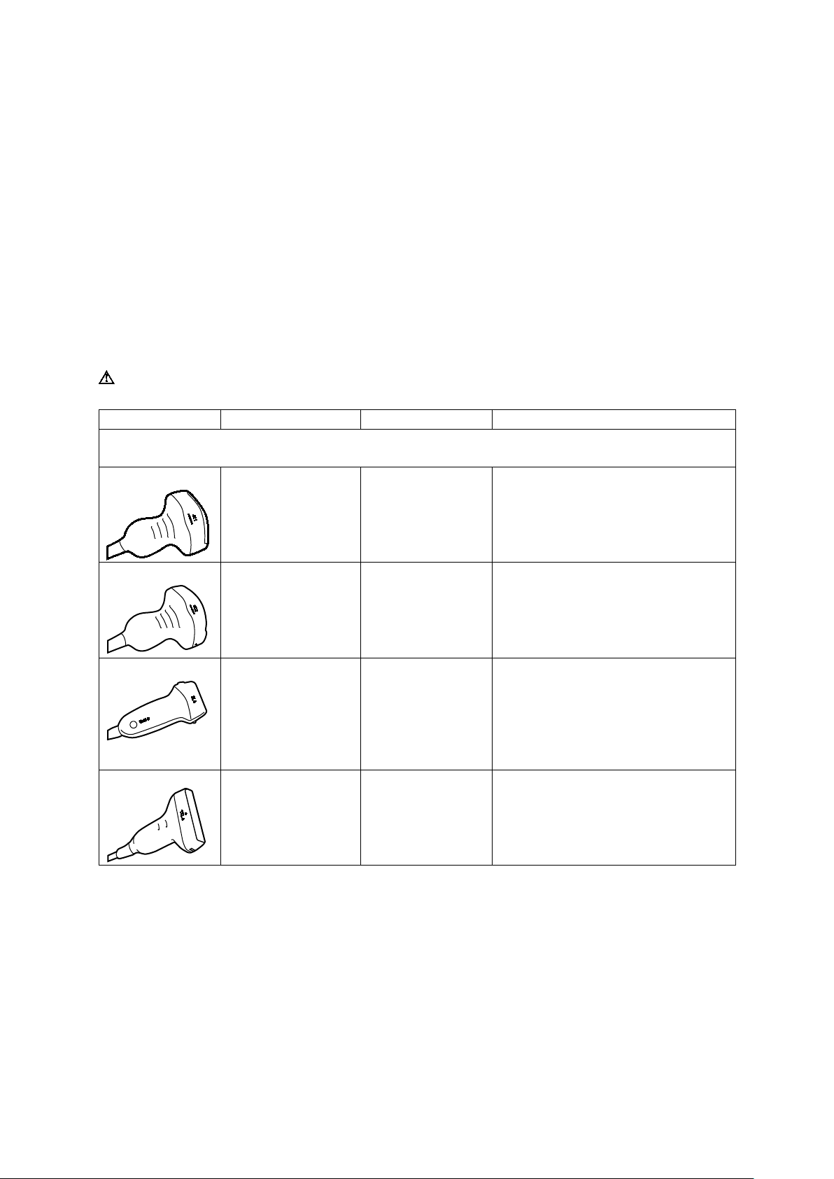
Transducers and Intended Applications
Refer to the table below for transducers compatible with these ultrasound systems:
ACUSON S1000 ultrasound system
ACUSON S2000 ultrasound system
ACUSON S3000 ultrasound system
Only the following transducers from Siemens are compatible with your ultrasound system.
EMC Note: Operating the transducer in close proximity to sources of strong electromagnetic fields,
such as radio transmitter stations or similar installations, may lead to temporary degradation or
interference visible on the monitor screen. A lightening of image background may be noticed while
visualizing hypoechoic structures, or color spectral interference, or jitter, or horizontal lines in the
image screen may occur. The transducer and the system have been designed and tested to
withstand such interference and will not be permanently damaged.
See also: Electromagnetic Emissions and Immunity: Guidance and Manufacturer's Declaration
WARNING: In accordance with Canadian law, the 14L5 SP transducer is not licensed for use
with the ACUSON S1000 ultrasound system or the ACUSON S3000 ultrasound system.
Curved and Linear Array Transducers
4C1
6C2
9L4
12L4
2D-mode:
2.0 MHz–4.5 MHz
Doppler:
2.0 MHz–3.5 MHz
2D-mode:
2.5 MHz–6.0 MHz
Doppler:
2.5 MHz–3.75 MHz
2D-mode:
4.0 MHz–9.0 MHz
Doppler:
4.0 MHz–6.75 MHz
2D-mode:
6.0 MHz–12.0 MHz
Doppler:
4.0 MHz–7.5 MHz
2D, C, D, M Fetal
Abdominal
2D, C, D, M Fetal
Abdominal
Pediatric
Peripheral Vessel
2D, C, D, M Fetal
Pediatric
Small Organ
Neonatal Cephalic
Peripheral Vessel
Musculo-skeletal Conventional
2D, C, D, M Pediatric
Small Organ
Peripheral Vessel
Musculo-skeletal Conventional
Instructions for Use 1 - 13
Page 24
1 Introduction
Transducer Name
Operating Frequency1
Modes of Operation2
Intended Applications
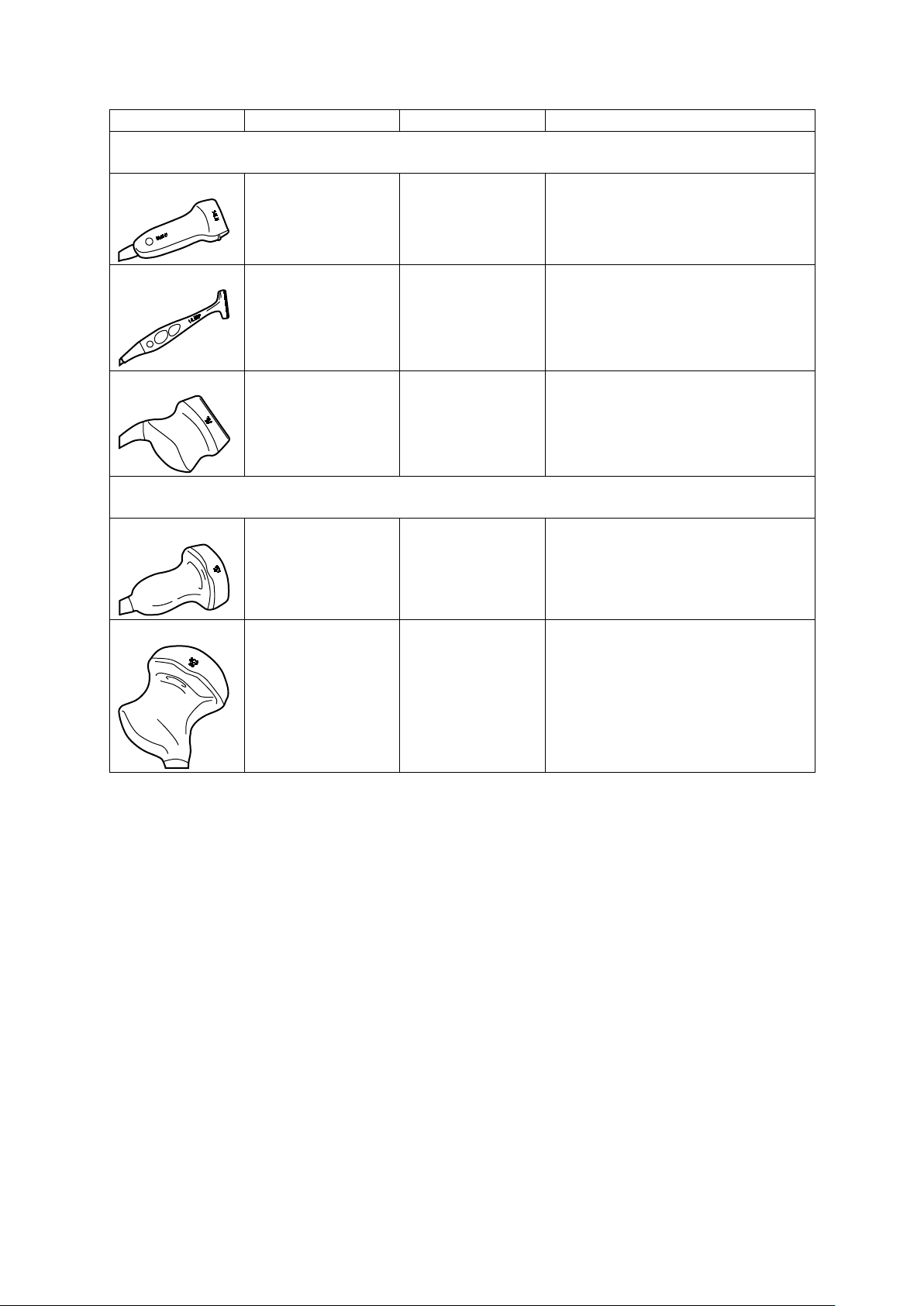
(Available on the ACUSON S1000 system, ACUSON S2000 system, and ACUSON S3000 system)
(Available only on the ACUSON S2000 system and the ACUSON S3000 system)
Curved and Linear Array Transducers
14L5
14L5 SP
18L6 HD
6C1 HD
8C3 HD
2D-mode:
6.0 MHz–14.0 MHz
Doppler:
5.5 MHz–7.5 MHz
2D-mode:
6.0 MHz–14.0 MHz
Doppler:
5.5 MHz–9.0 MHz
2D-mode:
7.0 MHz–17.0 MHz
Doppler:
5.5 MHz–10.0 MHz
Curved and Linear Array Transducers
2D-mode:
1.5 MHz–5.5 MHz
Doppler:
2.0 MHz–3.5 MHz
2D-mode:
3.0 MHz–8.0 MHz
Doppler:
2.85 MHz–3.75 MHz
2D, C, D, M Small Organ
Peripheral Vessel
Musculo-skeletal Conventional
2D, C, D, M Intraoperative
Small Organ
Peripheral Vessel
Musculo-skeletal Conventional
2D, C, D, M Small Organ
Peripheral Vessel
Musculo-skeletal Conventional
Musculo-skeletal Superficial
2D, C, D, M Fetal
Abdominal
2D, C, D, M Fetal
Abdominal
Pediatric
Small Organ
Peripheral Vessel
1 - 14 Instructions for Use
Page 25
1 Introduction
Transducer Name
Operating Frequency1
Modes of Operation2
Intended Applications
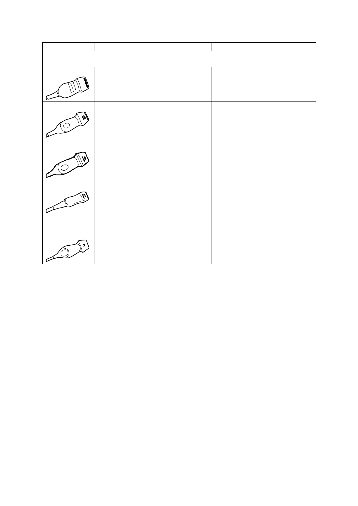
(Available on the ACUSON S1000 system, ACUSON S2000 system, and ACUSON S3000 system)
Other (Neonatal Cardiac)
Phased Array Transducers
4V1
4V1c
8V3
10V4
4P1
2D-mode:
2.0 MHz–4.5 MHz
Doppler:
2.0 MHz–3.5 MHz
2D-mode:
1.75 MHz–4.64 MHz
Doppler:
1.8 MHz–3.5 MHz
2D-mode:
4.0 MHz–8.0 MHz
Doppler:
2.5 MHz–5.0 MHz
2D-mode:
4.0 MHz–10.0 MHz
Doppler:
4.5 MHz–6.0 MHz
2D-mode:
1.75 MHz–4.64 MHz
Doppler:
2.0 MHz–3.5 MHz
2D, C, D, M Fetal
Abdominal
2D, C, D, M, CW Abdominal
Pediatric
Adult Cephalic
Cardiac
Other (Neonatal Cardiac)
2D, C, D, M, CW Fetal
Pediatric
Neonatal Cephalic
Cardiac
2D, C, D, M, CW Fetal
Abdominal
Pediatric
Neonatal Cephalic
Cardiac
Peripheral Vessel
2D, C, D, M, CW Fetal
Abdominal
Adult Cephalic
Cardiac
Instructions for Use 1 - 15
Page 26
1 Introduction
Transducer Name
Operating Frequency1
Modes of Operation2
Intended Applications
(Available on the ACUSON S1000 system, ACUSON S2000 system, and ACUSON S3000 system)
(Available on the ACUSON S1000 system, ACUSON S2000 system, and ACUSON S3000 system)
4.2 MHz–6.75 MHz
Phased Array Transducers
V5Ms
V7M
AcuNav 8F
AcuNav 10F
EV-8C4
2D-mode:
4.0 MHz–7.0 MHz
Doppler:
3.5 MHz–4.0 MHz
2D-mode:
4.0 MHz–8.0 MHz
Doppler:
3.5 MHz–4.75 MHz
2D-mode:
4.0 MHz–10.0 MHz
Doppler:
4.0 MHz–6.5 MHz
2D-mode:
4.0 MHz–10.0 MHz
Doppler:
4.0 MHz–6.5 MHz
2D-mode:
4.0 MHz–9.0 MHz
Doppler:
2D, C, D, M, CW Transesophageal
2D, C, D, M, CW Transesophageal
2D, C, D, M, CW Pediatric
Cardiac
Intracardiac
Other (Intraluminal)
2D, C, D, M, CW Pediatric
Cardiac
Intracardiac
Other (Intraluminal)
Endocavity Transducers
2D, C, D, M Fetal
Abdominal
Transvaginal
EC9-4
MC9-4
2D-mode:
4.0 MHz–8.0 MHz
Doppler:
3.75 MHz–6.75 MHz
2D-mode:
4.0 MHz–8.0 MHz
Doppler:
3.75 MHz–6.75 MHz
2D, C, D, M Fetal
Abdominal
Small Organ
Neonatal Cephalic
Transrectal
Transvaginal
2D, C, D, M Fetal
Abdominal
Small Organ
Neonatal Cephalic
Transrectal
Transvaginal
1 - 16 Instructions for Use
Page 27
1 Introduction
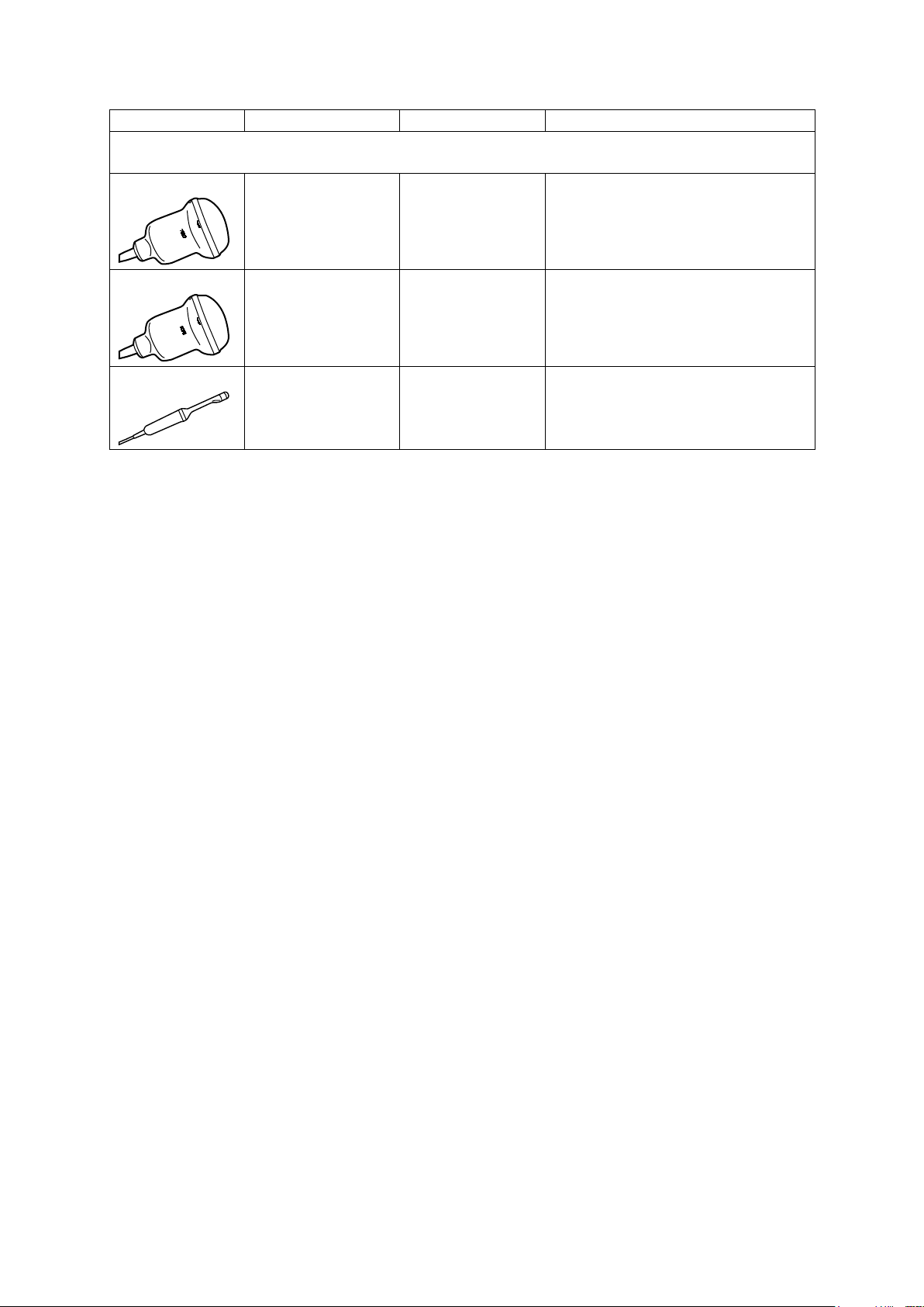
Transducer Name
Operating Frequency1
Modes of Operation2
Intended Applications
(Available on the ACUSON S1000 system, ACUSON S2000 system, and ACUSON S3000 system)
fourSight 4D Transducers
7CF1
7CF2
9EVF4
2D-mode:
3.0 MHz–7.0 MHz
Doppler:
2.5 MHz–3.75 MHz
2D-mode:
3.0 MHz–7.0 MHz
Doppler:
2.5 MHz–3.75 MHz
2D-mode:
4.0 MHz–9.0 MHz
Doppler:
4.0 MHz–7.5 MHz
2D, C, D, M Fetal
Abdominal
2D, C, D, M Fetal
Abdominal
2D, C, D, M Fetal
Neonatal Cephalic
Transvaginal
Instructions for Use 1 - 17
Page 28

1 Introduction
Transducer Name
Operating Frequency1
Modes of Operation2
Intended Applications
(Available on the ACUSON S1000 system, ACUSON S2000 system, and ACUSON S3000 system)
1
Operating Frequency
Range of selectable operating frequencies for:
2
Modes of Operation
Includes one or more of the following system operating modes
Continuous Wave Transducers
CW2
2.0 MHz CW Adult Cephalic
Cardiac
Peripheral Vessel
CW5
5.0 MHz CW Adult Cephalic
Cardiac
Peripheral Vessel
2D-mode Fundamental and harmonic imaging, not including contrast
Doppler Pulsed wave, continuous wave, and color imaging
2D (brightness mode) 2D-mode, 2D-mode with Tissue Harmonic Imaging (THI)
C (color flow Doppler) Color Doppler Velocity (CDV), Color Doppler Energy (CDE)
D (Doppler)
Pulsed Wave Doppler, 2D/Doppler, 2D/Doppler with CDV,
2D/Doppler with CDE
M (motion mode)
M-mode, M-mode with THI, 2D/M-mode, 2D/M-mode with CDV,
2D/M-mode with CDE
CW (continuous wave Doppler)
Steerable Continuous Wave Doppler (for phased array transducers),
Auxiliary Continuous Wave Doppler (for continuous wave [pencil]
transducers)
1 - 18 Instructions for Use
Page 29

1 Introduction
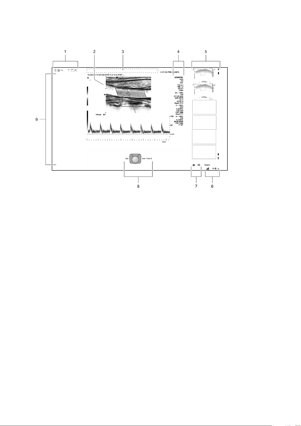
Image Screen Layout
The monitor on the ultrasound system displays clinical images together with important
operating parameters and patient data.
You can hide the thumbnail panel to increase the space available on the screen for the image.
For systems without a touch screen, you can also hide the soft key selections and menu
located on the left side of the screen.
Use the system configuration menu to customize the location of information within the patient
banner.
System Config > Patient Banner
Use the system configuration menu to configure the parameter settings in the imaging
parameters section of the screen.
System Config > Image Text Editor
Screen Saver
The screen saver feature automatically freezes the system and replaces the active display with
a screen-saver display after the system has been inactive for a specified number of minutes.
Exit the active screen saver display by pressing any key, adjusting any control, or rolling the
trackball. When the security package is activated on the ultrasound system, a user name and
password are required to exit the active screen-saver display and access the system.
Use the system configuration menu to select the duration of operational inactivity needed to
activate the screen saver.
System Config > Basic System
Note: The screen saver feature is not available when the system is in external video playback or
during the Biopsy function.
Instructions for Use 1 - 19
Page 30
1 Introduction
1 Toolbar buttons. Displays controls for system functions,
8 Trackball status. Indicates the function currently
Sample Image Screens
Example of a typical image screen.
for example, displaying or hiding the menu, accessing
the patient browser, and displaying information about
using the ultrasound system.
Displays the security icon when the security package is
activated.
2 Measured Results. Displays values for measurements
and calculations.
Drag the measured results to the required location.
3 Patient banner. Customizable information for identifying
the patient, operator, institution, date, and time.
4 Imaging Parameters. Displays a list of imaging
parameter settings for each active mode. Displays a clip
icon when the clip store function is activated.
5 Thumbnail Display. Displays reference images
(reduced-size images) of stored clips, images, and
volumes. Use the arrows on either end of the thumbnail
panel to scroll the thumbnails.
6 Displays information about the network connection and
network job status.
7 Controls for printing and deleting thumbnails.
assigned to the trackball and the controls adjacent to the
trackball.
For systems without a touch screen, this location
includes soft key selections available for the active mode
or function. Soft key selections correspond to the
controls and scroll wheel on the control panel directly
above the trackball.
9 Image menu. Displays controls and functions of the
optional software programs available during review.
Use the trackball pointer to expand or collapse the
display of selections for each section in the menu.
For systems without a touch screen, this location
includes mode-specific optimization parameters and
functions, measurement labels and tools, review
selections, and access to exam types and transducers.
1 - 20 Instructions for Use
Page 31

2 Safety and Care
Operating Safety and Environment ................................................................... 3
System Symbols ............................................................................................ 3
Labels .......................................................................................................... 11
Biohazard Considerations............................................................................ 13
Note on Fetal Examinations ................................................................. 14
Acoustic Output — Mechanical and Thermal Indices .................................. 15
Mechanical and Thermal Indices .......................................................... 16
Transmit Power Control ........................................................................ 16
Transmit Power Display........................................................................ 17
Imaging Functions that Change Acoustic Output ................................. 18
Transducer Surface Temperature Limits ..................................................... 19
Electrical Safety ........................................................................................... 20
Level of Protection Against Electrical Shock — System ....................... 21
Level of Protection Against Electrical Shock — Transducers ............... 21
Defibrillators ......................................................................................... 22
Defibrillator Use and the ACUSON AcuNav Ultrasound Catheter ........ 22
Implantable Devices ............................................................................. 22
Possible Combinations with Other Equipment ...................................... 23
Maintaining Data Integrity ............................................................................ 23
Data Compression ....................................................................................... 23
Caring for the Ultrasound System ................................................................... 24
Daily Checklist ............................................................................................. 24
Maintenance ................................................................................................ 25
Repair ................................................................................................... 25
Siemens Authorized Care..................................................................... 25
Caring for Documentation and Storage Devices .......................................... 26
Caring for the Battery Pack .......................................................................... 26
Recharging the Battery Pack ................................................................ 26
Battery Pack Replacement ................................................................... 26
Battery Pack Location .......................................................................... 27
Removing the Battery Pack .................................................................. 28
Installing a Battery Pack ....................................................................... 28
Recycling the Battery Pack ................................................................... 28
Cleaning and Disinfecting ............................................................................ 29
Cleaning Ultrasound System Surfaces ................................................. 29
Approved Disinfectant Wipes for the Ultrasound System Surfaces ...... 33
Cleaning the Air Filter ........................................................................... 34
Instructions for Use 2 - 1
Page 32

2 Safety and Care
Caring for Transducers .................................................................................... 36
Methods for Cleaning and Disinfecting Transducers ................................... 38
Examples of Transducer Components ................................................. 39
Cleaning and Disinfecting Transducers ................................................ 42
Approved List of Cleaners .................................................................... 44
Approved List of Disinfectants .............................................................. 45
Sterilizing Transducers — 14L5 SP ............................................................. 46
Caring for Transducer Accessories ................................................................ 47
Transducer Sheaths .................................................................................... 47
Storage ................................................................................................. 47
Gel Pad........................................................................................................ 48
Storage ................................................................................................. 48
Needle Guide Bracket Kits........................................................................... 48
Storage and Transportation .................................................................. 48
Cleaning, Disinfecting, and Sterilizing Transducer Accessories .................. 49
Needle Guide Bracket Kits ................................................................... 49
Environmental Protection ................................................................................ 51
Product Recycling and Disposal .................................................................. 51
Hazardous Substances ........................................................................ 51
Caring for Batteries ...................................................................................... 51
Recycling Batteries ...................................................................................... 52
Disposing of the Packaging Materials .......................................................... 52
Disposing of Components and Accessories ................................................ 53
Energy Conservation ................................................................................... 53
2 - 2 Instructions for Use
Page 33

2 Safety and Care
Symbol
Explanation
Operating Safety and Environment
Do not operate the ultrasound imaging system until you fully understand the safety
considerations and procedures presented in this manual.
System Symbols
The table below is provided for your identification of important symbols located on the
ultrasound imaging system and transducers:
Danger: Risk of explosion if used in the presence of flammable
anesthetics.
Caution: Risk of electric shock.
Do not open. Refer servicing to qualified service personnel.
Consult instructions for use
It is mandatory you refer to the manual.
(blue illustration)
Caution
(black illustration)
Note: For systems and transducers shipped from the factory
prior to 1 October 2010, the symbol means "Caution, consult
accompanying documents."
General Warning
(yellow and black illustration)
Standby — ON
ON only for MAINS control
OFF only for MAINS control
Monitor Tint
Monitor Brightness
USB Connection
Ethernet Connection
Instructions for Use 2 - 3
Page 34

2 Safety and Care
Symbol
Explanation
Control Panel Light or Indicator Light
Yellow Indicator Light
Status Indicator for DC Power Good (Green) or Green Indicator
Light
Printer Connection
Type BF Defibrillator-proof Patient Connection
Type BF Applied Part
Type B Patient Connection
Continuous Wave Transducer Port
Transducer Port
ECG Signal Connection
Electrocardiogram (EKG)
Signal Input
Signal Output
2 - 4 Instructions for Use
Page 35

2 Safety and Care
Symbol
Explanation
Footswitch Connector
Equipotential Connection
Protective Earth Ground
Do not install wet
Location of Air Filter
Insert this way
Battery
Recycle Ni-MH battery
Do not dispose of by burning
The product must be properly disposed of in accordance with
local, state, and regional laws and regulations.
Products bearing this symbol are subject to the European
Community directive 2002/96/EC on waste electrical and
electronic equipment (WEEE), amended by directive
2003/108/EC. For collection and disposal of the product, its
components, or its accessories, contact your local Siemens
representative.
Do not dispose of by flushing down lavatory
Instructions for Use 2 - 5
Page 36

2 Safety and Care
Symbol
Explanation
Pinch hazard.
Do not lean against the monitor.
Shelf Weight Restriction
Brake Engaged
Brake Released
Direction/Steer Lock
Manufacturer's declaration of product compliance with
applicable EEC directive(s) and the European notified body
DEMKO-Denmark approval mark
UL symbol for listing as recognized components for Canada and
United States of America
UL classified symbol for Canada and United States of America
EAC (Eurasian Conformity mark)
The Eurasian Conformity mark is a product marking to indicate
that the product conforms to all Technical Regulations of the
Customs Union assessment procedures
Equipment complies with the standard and specifications
published by IMDA (Info-communications Media Development
Authority of Singapore)
"XXXXXX" represents the dealer's license number
TÜV Rheinland INMETRO Certification Mark (Brazil)
Authorized representative in the European community
2 - 6 Instructions for Use
Page 37

2 Safety and Care
Symbol
Explanation
Location of device manufacturing: United States of America
Location of device manufacturing: Republic of Korea
Location of device manufacturing: Japan
Location of device manufacturing: Netherlands
(System Installierte Volumen Komponente)
Identifies the system for product traceability at Siemens
Healthcare
(Installierte Volumen Komponente)
Identifier of selected system components or parts for product
traceability
Gost-R symbol indicates that this product is certified for
conformity to the safety requirements of Russian state
standards
Caution: In the United States of America, federal law restricts
this device to sale or use by, or on the order of, a physician.
Safe working load
"XXX" represents the weight of the system unpacked and ready
for operation with documentation devices installed
Additional objects or devices on the system cannot exceed the
safe working load
Transducer storage temperature range (example)
System storage temperature range (example)
Unlock (left) and lock (right) positions
Protected against the effects of temporary immersion in water
Protected against the effects of continuous immersion in water
Barcode
Barcode with product identification information according to the
following barcode specification:
GS1 128 2D
Instructions for Use 2 - 7
Page 38

2 Safety and Care
Symbol
Explanation
Global Trade Item Number
Model revision
Serial number
Quantity of product
Siemens model number
Device part number
Manufacturer country of origin: United States of America
Manufacturer country of origin: Republic of Korea
Manufacturer country of origin: Japan
Manufacturer country of origin: Netherlands
Date of Manufacture symbol with the date below
Manufacturer
2 - 8 Instructions for Use
Page 39

2 Safety and Care
Symbol
Explanation
AC (alternating current) voltage source
Identifies voltage, frequency, and current rating of system
configuration for MAINS.
100V~, 50/60 Hz, 15A maximum draw, 15A MAINS breaker.
Identifies voltage, frequency, and current rating of system
configuration for MAINS.
115V~, 50/60 Hz, 12A maximum draw, 15A MAINS breaker.
Identifies voltage, frequency, and current rating of system
configuration for MAINS.
230V~, 50/60 Hz, 6.5A maximum draw, 7.5A MAINS breaker.
Identifies voltage and circuit breaker current.
Instructions for Use 2 - 9
Page 40

2 Safety and Care
Symbol
Explanation
Weight and size
"XXX" represents the weight of the system packaged for
shipping
"XX" represents the size of the box in inches
Do not stack
Recycle
Storage atmospheric pressure range (example)
Storage humidity range (example)
Indicates this side up
Do not stack
Shipping weight (example)
Do not allow to get wet
Fragile. Handle with care.
Refer to the operator's manual for information about compatible
needle guides.
Environmentally friendly use period
Intentional transmitter of non-ionizing radiation.
2 - 10 Instructions for Use
Page 41

2 Safety and Care
Labels
1 System warning label with certification
labels
Location of labels on the ultrasound system (example).
Instructions for Use 2 - 11
Page 42

2 Safety and Care
1 Identification label
2 Country-specific labels
3 Country-specific labels
Example of system label.
Example of identification label.
1 Product name
2 System input power requirement
2 - 12 Instructions for Use
Page 43

2 Safety and Care
Biohazard Considerations
WARNING: With the exception of systems licensed to use the ACUSON AcuNav catheter, this
equipment is not suitable for intracardiac use or direct cardiac contact.
See also: For additional information on the AcuNav catheter, refer to the user manual for the
catheter.
WARNING: This equipment is not suitable for intracardiac use or direct cardiac contact.
WARNING: For neonatal head imaging, Siemens recommends that you exercise special care
during neonatal cephalic scanning to avoid possible damage to the posterior region of the eye.
The ultrasound energy emitted by the transducer easily penetrates the fontanels of the infant.
WARNING: Siemens makes every effort to manufacture safe and effective transducers. You
must take all necessary precautions to eliminate the possibility of exposing patients, operators,
or third parties to hazardous or infectious materials. These precautions should be considered in
the use of any application that may indicate the need for such care, and during endocavity or
intraoperative scanning; during biopsy or puncture procedures; or when scanning patients with
open wounds.
WARNING: To eliminate the possibility of exposing patients, operators, or third parties to
hazardous or infectious materials, always dispose hazardous or infectious materials according to
local, state, and regional laws and regulations.
WARNING: Transducer sheaths: There have been reports of severe allergic reactions to
medical devices containing latex (natural rubber). Health care professionals are advised to
identify latex-sensitive patients and to be prepared to treat allergic reactions promptly. For
additional information in the U.S.A., refer to FDA Medical Alert MDA91-1.
WARNING: Ultrasound energy is transmitted more effectively through water than through tissue.
When using a standoff device of any kind, for example, a waterpath or gel pad, the actual
mechanical and thermal indices, MI and/or TI, may be higher than indicated in the output display
on the ultrasound system.
The assessment of the biological effects of diagnostic ultrasound on humans is a subject of
ongoing scientific research. This ultrasound system, and all diagnostic ultrasound procedures,
should be used for valid reasons, for the shortest possible period of time, and at the lowest
mechanical and thermal indices necessary to produce clinically acceptable images.
According to the principles of ALARA (As Low As Reasonably Achievable), the acoustic output
should be the lowest level required to satisfactorily perform the examination.
The ultrasound imaging system complies with the standards of the American Institute of
Ultrasound in Medicine (AIUM) and the National Electrical Manufacturer's Association (NEMA),
the guidelines of the United States Food and Drug Administration (FDA) and the standards of
the International Electrotechnical Commission (IEC) in terms of safety and acoustic output
levels. The ultrasound output levels are stated to permit the user to critically evaluate the
ultrasound system settings in the event of new research findings being announced.
Instructions for Use 2 - 13
Page 44

2 Safety and Care
Note on Fetal Examinations
The following recommendation is excerpted from the National Institute of Health in the United
States of America. Consensus Statement on the Use of Ultrasound Imaging During Pregnancy,
Volume 5, No. 1, based on the recommendation issued at the Health Consensus Development
Conference, February, 1984:
Ultrasound examination in pregnancy should be performed for a specific medical
indication. The data on clinical efficacy and safety do not allow a recommendation for
routine scanning at this time.
Ultrasound examination performed solely to satisfy the family's desire to know the fetal sex,
to view the fetus, or to obtain a picture of the fetus should be discouraged. In addition,
visualization of the fetus solely for educational or commercial demonstrations without
medical benefit should not be performed.
In August 1994, the Food and Drug Administration (FDA) notified the medical community and
the ultrasound industry regarding its concerns about the misuse of diagnostic ultrasound
equipment for non-medical purposes, and to discourage patients from having sonograms for
non-medical reasons.
The American Institute of Ultrasound in Medicine (AIUM) has also advocated the responsible
use of diagnostic ultrasound for all fetal imaging (August 2005).
2 - 14 Instructions for Use
Page 45

2 Safety and Care
Acoustic Output — Mechanical and Thermal Indices
WARNING: Ultrasound procedures should be used for valid reasons, for the shortest period of
time, and at the lowest mechanical/thermal index setting necessary to produce clinically
acceptable images.
The ultrasound system incorporates an output display of Mechanical and Thermal Indices to
allow you to monitor, and to limit, the amount of ultrasound energy that is transferred to the
patient.
Example of the mechanical and thermal indices and the transmit power display on the image screen.
1 Mechanical and thermal indices
2 Transmit power display
Note: For ultrasound systems distributed in the United States of America, refer to the Medical
Ultrasound Safety ultrasound education program brochure produced by the AIUM that is shipped with
the system.
Instructions for Use 2 - 15
Page 46

2 Safety and Care
Mechanical and Thermal Indices
The ultrasound system displays the Mechanical and Thermal Indices during real-time imaging,
in all imaging modes, when the Mechanical Index or the Thermal Indices are equal to or exceed
a value of 0.4.
Note: During exams using contrast agent imaging, the system always displays values for the
Mechanical Index (MI) and the Maximum of Mechanical Indices measured at the active focal zones
(MIF).
Indices display in the abbreviated form shown below:
MI: Mechanical Index
MIF: Maximum of the Mechanical Indices measured at the active focal zones (displayed
during contrast agent imaging exams only)
TIB: Bone Thermal Index (fetal application)
TIS: Soft Tissue Thermal Index
TIC: Cranial Thermal Index
Transmit Power Control
Adjust the transmit power and the corresponding acoustic pressure delivered through the
transducer to the patient by using the designated control on the ultrasound system. It is the
main system function that determines the transmitted intensity of ultrasound for all transducers
and imaging modes during real-time imaging, though it is not the only function that affects the
mechanical and thermal indices. The range and especially the maximum level of the
mechanical and thermal indices differ depending on the transducers. In addition, each
diagnostic exam type has preset values for mechanical and thermal indices.
Note: Maximum transmit acoustic intensity and the mechanical index for each exam type is limited in
accordance with the United States Food and Drug Administration's (FDA) recommendations and
guidelines. System default transmit intensity and mechanical index values are always below the FDA
recommendations for each exam type. Although some exam types may default to a condition of
maximum allowable transmit power, there are other system controls or functions that could raise
acoustic output levels.
To increase the transmit power during real-time imaging:
● Rotate the [Transmit Power] control located below the touch screen clockwise to increase
transmit power.
○ For systems without a touch screen, press the TX POWER control on the control panel
upward to increase transmit power.
To decrease the transmit power during real-time imaging:
● Rotate the [Transmit Power] control located below the touch screen counterclockwise to
decrease transmit power.
○ For systems without a touch screen, press the TX POWER control on the control panel
downward to decrease transmit power.
2 - 16 Instructions for Use
Page 47

2 Safety and Care
Adjusting the Transmit Power during Contrast Agent Imaging
During contrast agent imaging, you can also increase or decrease the transmit power. The
transmit power range is from 0.10% to 100% for contrast agent imaging.
● Rotate the [Power] control located below the touch screen clockwise to increase transmit
power. Rotate the [Power] control counterclockwise to decrease transmit power.
○ For systems without a touch screen, rotate the [Power] LED panel control clockwise to
increase transmit power. Rotate the [Power] control counterclockwise to decrease transmit
power.
Transmit Power Display
The transmit power range is from 0% to 100%. Selecting 100%, in combination with other
ultrasound system controls or functions, generates the maximum acoustic intensity and
mechanical index for each transducer, where:
I
: ≤ 720 mW/cm2 and MI ≤ 1.9
SPTA.3
Instructions for Use 2 - 17
Page 48

2 Safety and Care
Imaging Functions that Change Acoustic Output
WARNING: Observe the real-time display of mechanical and thermal indices (MI/TI) at all times.
In addition to the adjustment of the transmit power, adjustment of the following imaging
functions and/or controls may affect the acoustic output:
Automatic Time-out Imaging Mode
Color Ensemble Size Line Density/Resolution
Color ROI Position M-mode ROI Position
Color ROI Size Multi-Frequency
Doppler Gate Position
Doppler Color PRF Presets
Doppler Gate Size Reset
Exam Type Transducer
Field of View (Scan Angle) Transmit Power
Focus Update
Frame Rate Gel Pad
Freeze Zoom
Image Depth
Power On/Off
2 - 18 Instructions for Use
Page 49

2 Safety and Care
Transducer
TMM
Still Air
38.6°C
35.9°C
40.7°C
40.5°C
41.4°C
41.0°C
36.0°C
36.7°C
41.1°C
Transducer Surface Temperature Limits
The following table provides the maximum surface temperature of the transducers compatible
with the system.
Maximum surface temperatures are in accordance with IEC 60601-2-37.
Maximum Temperature
4C1
6C1 HD
6C2
8C3 HD
9L4
12L4
14L5
14L5 SP
18L6 HD
4P1
4V1
4V1c
8V3
10V4
V5Ms
V7M
EV-8C4
EC9-4
MC9-4
7CF1
7CF2
9EVF4
CW2
CW5
AcuNav 8F
AcuNav 10F
TMM = Tissue Mimicking Material
NA = not applicable (not tested)
≤
≤ 41.0°C ≤ 38.0°C
≤ 40.1°C ≤ 40.0°C
≤ 41.0°C ≤ 42.5°C
≤ 39.4°C ≤ 38.1°C
≤ 42.5°C ≤ 47.0°C
≤ 41.7°C ≤ 41.1°C
≤
≤ 42.9°C ≤ 43.0°C
≤ 40.9°C ≤ 42.6°C
≤ 40.3°C ≤ 40.8°C
≤ 42.3°C ≤ 46.0°C
≤
≤ 37.7°C ≤ 36.5°C
≤ 36.4°C ≤ 39.4°C
≤ 42.6°C ≤ 40.3°C
≤ 38.9°C ≤ 39.6°C
≤
≤ 42.5°C ≤ 45.3°C
≤ 38.6°C ≤ 45.0°C
≤ 36.7°C ≤ 37.2°C
≤ 38.4°C ≤ 38.3°C
≤ 36.9°C ≤ 37.7°C
≤ 35.3°C ≤ 37.7°C
≤
≤ 39.6°C
≤
≤
≤
≤
NA
NA
Instructions for Use 2 - 19
Page 50

2 Safety and Care
Electrical Safety
WARNING: To avoid electric shock, use a protective earth connection to connect the ultrasound
system to the mains power supply. The protective earth connection ensures that the mains
circuit breaker will disconnect the power supply in the event of a short circuit.
WARNING: For 115V ultrasound systems: To ensure grounding reliability, only connect the
system to a hospital-grade power outlet.
WARNING: The AC power connector plug for the ultrasound system is a three-prong grounded
plug (in the U.S.A.) and should never be adapted to any two-prong (non-grounded) outlet, either
by modifying the plug or by using an adapter. In the U.S.A., proper grounding requires the
AC power connector plug to be plugged into a hospital-grade power outlet.
WARNING: To avoid electrical shock, never modify the ultrasound system AC power connector
plug, as doing so may overload your facility's power circuits. To ensure grounding reliability,
connect the system only to an equivalent outlet.
WARNING: To avoid electrical shock, never use equipment or a mains power cord that shows
signs of wear or tampering, or that has a ground plug which has been bypassed by using an
adapter.
WARNING: Equipment connected to the ultrasound system and in the patient zone must be
powered from a medically-isolated power source or must be a medically-isolated device.
Equipment powered from a non-isolated source can result in chassis leakage currents
exceeding safe levels. Chassis leakage current created by an accessory or device connected to
a non-isolated outlet may add to the chassis leakage current of the ultrasound system.
WARNING: Using an extension cord or multi-socket outlet setup to provide power to the
ultrasound system, or to the system's peripheral devices may compromise the system grounding
and cause your system to exceed leakage current limits.
WARNING: To avoid electrical shock and damage to the ultrasound system, power off and
unplug the equipment from the AC power outlet before cleaning and disinfecting.
WARNING: To avoid electrical shock and damage to the control panel resulting from ingress of
liquid, place the gel bottle and gel warmer on the side of the system closest to the patient.
WARNING: To prevent excessive leakage current from contacting the patient, do not touch a
user-accessible connector on the system while touching or scanning the patient. Useraccessible connectors include the ECG connector, a USB connector, and any other audio,
video, or data transmission connectors.
WARNING: Connecting peripheral devices to accessory outlets on the ultrasound system
effectively creates a medical electrical system, resulting in a reduced level of safety.
WARNING: Do not modify this equipment without authorization from Siemens.
2 - 20 Instructions for Use
Page 51

2 Safety and Care
Caution: To avoid the possibility of static shock and damage to the system, avoid the use of
aerosol spray cleaners on the monitor screens.
Caution: Do not use spray cleaners on the ultrasound system, as this may force cleaning fluid
into the system and damage electronic components. It is also possible for the solvent fumes to
build up and form flammable gases or damage internal components.
Caution: Do not pour any fluid onto the ultrasound system surfaces, as fluid seepage into the
electrical circuitry may cause excessive leakage current or system failure.
Caution: To ensure proper grounding and leakage current levels, it is the policy of Siemens to
have an authorized Siemens representative or Siemens approved third party perform all
on-board connections of documentation and storage devices to the ultrasound system.
Caution: To maintain the safety and functionality of the ultrasound system, maintenance must
be performed every 24 months. Electrical safety tests must also be performed at regular
intervals as specified by local safety regulations, or as needed.
EMC Note: Proximity to sources of strong electromagnetic fields, such as radio transmitter stations
or similar installations may lead to interference visible on the monitor screen. However, the device
has been designed and tested to withstand such interference and will not be permanently damaged.
Level of Protection Against Electrical Shock — System
According to EN 60601-1 and IEC 60601-1, the system provides a "Level of Protection Against
Electrical Shock" of "Type B."
The Type B icon is located on the system.
Level of Protection Against Electrical Shock — Transducers
According to EN 60601-1 and IEC 60601-1, the assemblies for the endocavity transducer and
the linear, curved, and phased array transducers provide a "Level of Protection Against
Electrical Shock" of "Type BF."
The Type BF icon is located on the transducer label.
Example of a transducer label.
Instructions for Use 2 - 21
Page 52

2 Safety and Care
Defibrillators
WARNING: The ECG function is designed to withstand the effects of defibrillation. However,
when possible, disconnect the ECG leads during defibrillation since a malfunction of the safety
controls could otherwise result in electrical burns for the patient.
For patient safety, be sure to use defibrillators that do not have grounded patient circuits.
Defibrillator Use and the ACUSON AcuNav Ultrasound Catheter
WARNING: The catheter is designed to withstand the effects of defibrillation. However, when
possible, disconnect the connector from the ultrasound system during defibrillation because a
malfunction of the safety controls could otherwise result in electrical burns for the patient.
The catheter is designed to withstand the effects of defibrillation. There are no exposed
conductive surfaces distal to the handle. Within the flexible shaft, a chassis ground shield
covers all active circuits and conductors.
Recovery Time After Defibrillation During a Catheter Procedure
If you disconnect the SwiftLink catheter connector from the ultrasound system before
defibrillation, the recovery time after defibrillation is equal to the time required to reconnect the
connector to the ultrasound system.
The recovery time after defibrillation for the ultrasound system:
Three (3) minutes if defibrillation is performed with the ultrasound system on.
Implantable Devices
WARNING: Ultrasound systems, like other medical equipment, use high-frequency electrical
signals that can interfere with implantable devices such as pacemakers and implantable
cardioverter-defibrillators (ICDs). If the patient has such an implantable device, you should be
aware of any interference in its operation and immediately power off the ultrasound system.
2 - 22 Instructions for Use
Page 53

2 Safety and Care
Possible Combinations with Other Equipment
WARNING: Accessory equipment connected to the analog and digital interfaces must be
certified according to the respective EN and IEC standards (for example, EN 60950 and
IEC 60950 for data processing equipment and IEC 60601-1 for medical equipment). Anyone
who connects additional equipment to any of the signal input or signal output ports configures a
medical system and is therefore responsible that the system complies with the requirements of
the system standards IEC 60601-1. Siemens can only guarantee the performance and safety of
the devices listed in the Instructions for Use. If in doubt, consult the Siemens service department
or your local Siemens representative.
The ultrasound system supports a maximum of three documentation devices connected to the
system. Depending on how your system is configured, certain documentation devices will
maintain power when the system is powered off. Although this will not cause harm to your
documentation device, Siemens recommends that you power off each device whenever the
system is powered off.
Some on-board peripheral devices must be installed by an authorized Siemens representative
or by a Siemens-approved third party. Devices installed by other people will be at the user's risk
and may void the system warranty.
Maintaining Data Integrity
Important Information
To ensure data integrity:
To prevent the loss of data that results from power failures and other system "down"
occurrences, you must archive important data, such as patient records, onto an external
recording media, such as a CD or a network.
Loss of data is to be expected and its retrieval is not normally possible under the following
conditions: loss of power to the ultrasound system, hard disk failure, CPU failure, system
lockup, and other similar causes.
Should an abnormal system shutdown occur, retrieval of data not saved to the hard disk or
not archived to an external recording media is not normally possible.
An abnormal system shutdown occurs if you do not power off the ultrasound system using
the green partial power on/off switch ( ) located on the front of the system. Other
examples of abnormal system shutdown include: equipment malfunction, loss of power, or
pressing and holding the green partial power on/off switch longer than 4 seconds.
Should an abnormal system shutdown occur, the system may initially require additional
time to reboot or to respond to user input. This is due to the operating system performing a
background scan of the hard disk to detect and segregate any truncated or corrupted files.
Data Compression
WARNING: This product uses JPEG Lossy compression that is irreversible and can result in the
loss of image quality. All compressed images contain information about the compression ratio
and compression type. This product conforms to the DICOM standard. DICOM conformance
statements for ultrasound products are available at www.siemens.com/dicom.
Instructions for Use 2 - 23
Page 54

2 Safety and Care
Caring for the Ultrasound System
It is the responsibility of the user to verify that the ultrasound system is safe for diagnostic
operation on a daily basis. Each day, prior to using the system, perform each of the steps in the
Daily Checklist.
All exterior parts of the ultrasound system, including the control panel, keyboard, transducers,
and biopsy devices, should be cleaned and/or disinfected as necessary or between uses. Clean
each component to remove any surface particles. Disinfect components to destroy pathogens
and other microorganisms.
The ultrasound system has removable, washable air filters. The filters must be cleaned
regularly to maintain proper system cooling. Check the air filters weekly, and clean as needed.
Daily Checklist
WARNING: To minimize the risk of cross-contamination and infectious diseases, a sterile,
non-pyrogenic transducer sheath must be in place during procedures requiring sterility.
WARNING: To avoid electrical shock, you must visually inspect a transducer prior to use. Do not
use a transducer that has a cracked, punctured, or discolored casing or a frayed cable.
Discoloration Exception: The use of approved cleaners and disinfectants may cause
discoloration of the transducer. You can continue to use a transducer discolored due to the use
of approved cleaners and disinfectants only.
Perform the following each day before using the ultrasound system:
Visually inspect all transducers. Do not use a transducer that has a cracked, punctured, or
discolored casing or a frayed cable.
Visually inspect all power cords. Do not power on the ultrasound system if a cord is frayed
or split, or shows signs of wear.
Visually inspect the ECG connector and the cable. Do not use the ECG function if the
connector or cable is damaged or broken.
Verify that the trackball, DGC slide controls, and other controls on the control panel appear
clean and free from gel or other contaminants.
Once the ultrasound system is powered on:
Visually check the on-screen displays and lighting.
Verify that the monitor displays the current date and time.
Verify that the transducer identification and indicated frequency are correct for the active
transducer.
2 - 24 Instructions for Use
Page 55

2 Safety and Care
Maintenance
Caution: To maintain the safety and functionality of the ultrasound system, maintenance must
be performed every 24 months. Electrical safety tests must also be performed at regular
intervals as specified by local safety regulations, or as needed.
Repair
For questions regarding repair or replacement of any equipment parts on your system, contact
your Siemens service representative.
Siemens Authorized Care
Installers and operators must observe any statutory regulations that govern the installation,
operation, inspection, and maintenance of this equipment.
To ensure the safety of patients, operators, and third parties, the equipment must be inspected
every 24 months, and the replacement of parts is performed as necessary. This maintenance
must be performed by a qualified Siemens authorized representative. It is important to inspect
the equipment more frequently if it is operated under extraordinary conditions.
Perform inspections and maintenance at the prescribed intervals to avoid worn and hazardous
parts due to wear. Contact the Siemens service department for information regarding the
required maintenance.
As manufacturers and installers of ultrasound equipment, Siemens cannot assume
responsibility for the safety properties, reliability, and/or performance of the equipment, if:
Installations, extensions, readjustments, modifications, additions, or repairs are carried out
by persons not specifically authorized by Siemens.
Components that affect the safe operation of the system are replaced by parts not
authorized by Siemens.
The electrical installation of the room where the equipment is located does not meet the
power and environmental requirements stated in this manual.
The equipment is not used in accordance with the operating instructions.
The system is operated by personnel not adequately educated or trained.
Siemens suggests that you request any person who performs maintenance or repairs to
provide you with a certificate showing:
The nature and extent of the work performed
Changes in rated performance
Changes in working ranges
Date of service
Name of person or firm performing the service
Signature of person performing the service
Technical documentation pertinent to the ultrasound system is available at an additional
charge. However, this does not in any way constitute an authorization to conduct repairs or
maintenance. Siemens refuses all responsibility whatsoever for repairs that are performed
without the express written consent of the Siemens service department.
Instructions for Use 2 - 25
Page 56

2 Safety and Care
AC Tray Panel
Typical Time to Recharge
Maximum Time to Recharge
Caring for Documentation and Storage Devices
For information on the care of an optional documentation or storage device, refer to the
manufacturer's operating instructions that accompanied the device.
Caring for the Battery Pack
Recharging the Battery Pack
See also: Hazardous Substances, p. 2-51
The battery pack is designed to maintain system memory for a minimum of four hours.
1.8 hours 2 hours
Battery Pack Replacement
Replace the battery pack when it is no longer able to hold a charge.
When the system is disconnected frequently from the AC power (for a duration of greater
than four to eight hours), replace the battery every 12 to 18 months.
When the system is only occasionally disconnected from the AC power (for a duration of
approximately four hours), replace the battery every three years.
1 Battery pack charge
indicator LED
2 AC OK indicator LED
3 Mains ON-OFF circuit
breaker
Example of an AC Tray panel with the battery pack charge indicator LED.
The battery pack charge indicator LED is located at the rear of the system, on the AC Tray
panel. A green blinking LED indicates that the battery is actively charging. A solid green LED
indicates that the battery pack is fully charged. If the LED is not illuminated, then there is a
problem with the battery pack, or the battery pack may be missing.
2 - 26 Instructions for Use
Page 57

2 Safety and Care
Battery Pack Location
The battery pack is located under the storage bin cover, within a recess on the right rear panel
of the ultrasound system. The storage bin cover must be removed to access the battery pack.
1 Storage bin cover
2 Battery pack location
3 Battery symbol
Battery pack location.
To remove the storage bin cover:
1. Grasp the cover by the top right edge, above the battery location, and gently pull to unsnap
the first of four fastener pins from its receptacle.
2. Support the cover near each fastener as you pull, working downward and toward the left,
until the cover is removed.
Instructions for Use 2 - 27
Page 58

2 Safety and Care
Removing the Battery Pack
Caution: When removing the battery pack, be careful not to pull or otherwise strain the wires in
the cable connecting the battery to the ultrasound system because doing so can damage the
battery pack and the ultrasound system.
To remove the battery pack:
1. With the storage bin cover removed, locate the battery pack within the recess on the right
rear panel. The battery pack is attached to the ultrasound system by a connector at the
end of a cable. The battery is also secured within the recess by hook and loop fastener.
2. Grasp the battery pack within the recess and gently pull the battery pack to release the
hook and loop fastener.
3. Support the connector housing attached to the battery cable and pull the connector straight
out of the connector receptacle to disconnect the battery.
Installing a Battery Pack
Caution: There is only one correct orientation for attaching the battery connector. Do not force
or twist the connector because doing so can damage the battery pack and the ultrasound
system.
To install a battery pack:
1. Orient the battery pack connector at the end of the battery cable with the receptacle on the
ultrasound system, located within the battery recess. Firmly push them together.
2. Turn the battery pack so that the hook and loop fastener on the battery pack is toward the
battery recess in the right rear panel, and press the battery pack into the recess,
connecting the hook and loop fastener on the battery pack with the hook and loop fastener
in the recess.
3. Position the battery wires so they are neatly stored within the battery recess.
To replace the storage bin cover:
Working from the lower left toward the upper right of the storage bin cover, align the
fastener pins with the pin receptacles and press to snap the storage bin cover into place on
the right rear panel.
Recycling the Battery Pack
See also: Recycling Batteries, p. 2-52
2 - 28 Instructions for Use
Page 59

2 Safety and Care
Cleaning and Disinfecting
You must take all necessary precautions to eliminate the possibility of exposing patients,
operators, or third parties to hazardous or infectious materials. Use universal precautions when
cleaning and disinfecting. You should treat all portions of the ultrasound system that come in
contact with human blood or other body fluids as if they were known to be infectious.
All exterior parts of the ultrasound system, including the control panel, keyboard, transducers,
and biopsy devices, should be cleaned and/or disinfected as necessary or between uses. Clean
each component to remove any surface particles. Disinfect components to destroy pathogens
and other microorganisms.
Cleaning Ultrasound System Surfaces
WARNING: To avoid electric shock and damage to the ultrasound system, power off and unplug
the equipment from the AC power outlet before cleaning and disinfecting.
WARNING: Disinfectants and cleaning methods listed are recommended by Siemens for
compatibility with product materials, not for biological effectiveness. Refer to disinfectant label
instructions for guidance on disinfection efficacy and appropriate clinical uses.
WARNING: The use of any disinfectants other than those specified in the instructions for use
may damage the ultrasound system and accessory surfaces and, as a result, may create
electrical hazards for the patients and/or users.
Caution: To avoid the possibility of static shock and damage to the ultrasound system, avoid the
use of aerosol spray cleaners on the monitor screens.
Caution: Do not clean the ultrasound system with chlorinated or aromatic solvents, acidic or
basic solutions, isopropyl alcohol or strong cleaners such as ammoniated products, as these can
damage the surface of the system. Use the recommended cleaning procedure.
Caution: Do not use spray cleaners on the ultrasound system, as this may force cleaning fluid
into the system and damage electronic components. It is also possible for the solvent fumes to
build up and form flammable gases or damage internal components.
Caution: Do not pour any fluid onto the ultrasound system surfaces, as fluid seepage into the
electrical circuitry may cause excessive leakage current or system failure.
Caution: Prior to cleaning or disinfecting the system, you must disconnect and remove
transducers from the ultrasound system. Unintended contact with disinfectants approved only
for use with the system can result in damage to the transducers.
Instructions for Use 2 - 29
Page 60

2 Safety and Care
The following instructions describe cleaning the surface of the ultrasound system, including the
trackball and transducer holder.
To Do This
Clean and disinfect the
surface of the ultrasound
system
1. Power off the ultrasound system and unplug the power cord from the power outlet.
2. Use a clean gauze pad or lint-free cloth, lightly moistened with a mild detergent, to
wipe the surface of the ultrasound system.
If your system has a touch screen, take care to gently wipe the surface of the touch
screen.
Take particular care to clean the areas near the trackball and the slide controls.
Ensure these areas are free of coupling agent (gel) and any other visible residue.
Ensure that cleaning solution does not seep into the control panel, keyboard, or
any other openings.
3. After cleaning, use a clean, lint-free cloth to dry the surface.
4. As required, use an approved disinfectant wipe to disinfect the ultrasound system
and accessories.
5. Reconnect the ultrasound system power cord into the power outlet.
Clean and disinfect the
holders for transducers and
coupling gel
1. Remove the holder from the ultrasound system.
a. Reach under the holder to locate the tab on the holder. The tab extends below
the point of attachment to the ultrasound system.
b. Squeeze the tab towards the holder and pull the holder downward.
2. Clean the holder under running water, using a mild detergent and dry with a
lint-free cloth.
3. As required, use an approved disinfectant wipe to disinfect the holder.
4. Reattach the holder to the ultrasound system.
Align the support on the holder directly below the point of attachment on the
ultrasound system and firmly push upwards until the holder snaps into place.
2 - 30 Instructions for Use
Page 61

2 Safety and Care
To
Do This
Clean and disinfect the gel
warmer
Caution: To avoid damage to the gel warmer, do not immerse the gel warmer in
water or any solution.
Note: To facilitate cleaning, remove the cap at the bottom of the gel warmer. Rotate
the cap counterclockwise to remove the cap; rotate the cap clockwise to secure the
cap.
1. Remove the gel warmer from the ultrasound system.
a. Unplug the power cable attached to the gel warmer from the ultrasound system.
The connector on the ultrasound system is located on the right or left side of the
control panel, just behind the point of attachment for the gel warmer.
b. Reach under the gel warmer to locate the tab on the gel warmer. The tab
extends below the point of attachment to the ultrasound system.
c. Squeeze the tab towards the gel warmer and pull the gel warmer downward.
2. Unplug the power cable from the gel warmer.
3. Clean and disinfect the gel warmer using an approved disinfectant wipe.
4. Reattach the gel warmer to the ultrasound system.
a. Attach one end of the power cable accompanying the gel warmer to the
connector on the back of the gel warmer and then attach the other end of the
power cable to the connector on the ultrasound system.
b. Align the support on the gel warmer directly below the point of attachment on the
ultrasound system and firmly push upwards until the gel warmer snaps into
place.
Instructions for Use 2 - 31
Page 62

2 Safety and Care
To
Do This
Example of the trackball ring.
Example trackball assembly.
Clean and disinfect the
trackball
Caution: Do not drop or place foreign objects inside the trackball assembly
because doing so may affect the trackball operation and damage the ultrasound
system.
1 Tab for inserting into the trackball
assembly
2 Raised markings on either side of the
ring
1 Point of attachment for the trackball
ring
1. Rotate the ring around the trackball counterclockwise and then carefully lift up the
ring to remove the ring and trackball.
2. Clean the ring and trackball with a cotton swab or lint-free pad moistened with mild
detergent solution.
3. Clean the inside of the trackball assembly with a cotton swab or lint-free pad
moistened with mild detergent solution.
4. As required, use an approved disinfectant wipe to disinfect the ring, trackball, and
trackball assembly.
5. Allow the trackball components to completely dry before reassembly.
6. Reinstall the ring and trackball.
a. Place the trackball inside the trackball assembly.
b. Place the ring over the trackball, taking care to align the tab with the point of
attachment on the trackball assembly.
c. Rotate the ring clockwise until the ring snaps into place and the ridges of the ring
are in a horizontal position.
2 - 32 Instructions for Use
Page 63

2 Safety and Care
Sani-Cloth
Bleach Wipe*
Sani-Cloth HB
Plus
Sani-Cloth
Trackball Assembly
Gel Warmer
Approved Disinfectant Wipes for the Ultrasound System Surfaces
The following matrix provides a list of approved disinfectant wipes for use on the ultrasound
system and surfaces of the listed accessories.
Ultrasound System
Transducer Holders
*or any bleach wipe with <1% sodium hypochlorite and no other active ingredients
= approved
NA = not approved
Sani-Cloth
Sani-Cloth
Super
Instructions for Use 2 - 33
Page 64

2 Safety and Care
Cleaning the Air Filter
The filter location is marked with the air filter symbol.
The ultrasound system has one removable, washable air filter. This air filter must be cleaned
regularly to maintain proper system cooling. Check the air filter weekly, and clean as needed.
Clean and reinstall the air filter according to the following instructions.
1 Location of back panel air filter
Example of the location of the air filter.
2 - 34 Instructions for Use
Page 65

2 Safety and Care
To remove and clean the back panel air filter:
Caution: Do not scrub, stretch, or bend the filter, or apply heat to the filter, as doing so could
damage the filter.
1. Power off and unplug the power cord from the power outlet.
2. Locate the air filter tray in the back panel and pull the tray out of the ultrasound system.
3. Remove the air filter from the tray.
4. Rinse the air filter with running water and allow the filter to completely dry.
To hasten drying, you may gently shake the filter, or blot the filter with a clean, lint-free
cloth.
Caution: Do not insert a wet filter as this can damage the system.
5. Replace the air filter into the tray, positioning the filter flat side down, with the angled
corners fitting into the back of the tray. The filter will fit into the back corners of the tray only
if the filter is positioned flat side down.
6. Press the filter against the hook and loop fasteners on the tray.
7. Slide the air filter tray back into the ultrasound system.
8. Plug the power cord into the power outlet.
Instructions for Use 2 - 35
Page 66

2 Safety and Care
Caring for Transducers
WARNING: To minimize the risk of cross-contamination and infectious diseases, clean and
high-level disinfect endocavity transducers after each use; clean and sterilize intraoperative
transducers after each use.
WARNING: During neurosurgical procedures, if a transducer becomes contaminated with tissue
or fluids of a patient known to have Creutzfeldt-Jacob disease, the transducer should be
destroyed as it cannot be sterilized.
WARNING: When using an endocavity or intraoperative transducer with a BF or CF type applied
part, the patient leakage currents may be additive.
WARNING: Prior to each use, inspect the endocavity or intraoperative transducer for signs of
mechanical damage such as cracks, cuts, tears, perforations, or protrusions. Do not use the
transducer if the transducer appears damaged in any way. Any damage could cut the patient
and compromise the electrical safety of the transducer, causing possible patient or user injury.
Contact your local Siemens representative.
Caution: Transducers are sensitive instruments — irreparable damage may occur if they are
dropped, knocked against other objects, cut, or punctured. Do not attempt to repair or alter any
part of a transducer, contact your local Siemens representative.
Caution: To avoid cable damage, do not roll the ultrasound system over transducer cables.
Caution: To avoid damage to the transducer, do not use transducer sheaths containing an
oil-based coating or petroleum- or mineral oil-based ultrasound coupling agents. Use only a
water-based ultrasound coupling agent.
Caution: Follow all instructions provided by manufacturers of sterile goods (transducer sheaths)
to ensure proper handling, storage, and cycling of all sterile goods.
Take extreme care when handling or storing transducers. They must not be dropped, jarred, or
knocked against other objects. Do not allow transducers to come into contact with any
sharp-edged or pointed object.
2 - 36 Instructions for Use
Page 67

2 Safety and Care
Protective Case
Due to the mechanical sensitivity of transducers, Siemens recommends that you always use
the transducer case when you ship a transducer or transport it from one place of examination to
another. The case is specially designed to protect the sensitive parts of the transducer. Be sure
that all parts of the transducer are properly placed inside the case before you close the lid.
Storage
Store transducers in a clean and dry environment. Extreme temperatures or humidity may
damage a transducer.
See also: Technical Description, Appendix A, Instructions for Use.
Repair
Do not attempt to repair or alter any part of the transducer. Contact your service representative
at Siemens immediately if a transducer appears to be damaged or malfunctions in any way.
Instructions for Use 2 - 37
Page 68

2 Safety and Care
Example of Transducers
Use
Required Method
Classification
Laparoscopic
Methods for Cleaning and Disinfecting Transducers
You must observe the required methods for cleaning and disinfecting or cleaning and
sterilization before the first use and after each use of a transducer.
Siemens defines the methods for cleaning and disinfecting or cleaning and sterilization by
classifying the use of the transducer according to the Spaulding Classification scheme
observed by the United States Food and Drug Administration (FDA).
Intraoperative
Endocavity
Transesophageal
Non-invasive Non-intact skin
Non-invasive Intact skin
Sterile body tissue Cleaning and sterilization Critical
Intact mucous membranes
Cleaning and high-level
disinfection
Cleaning and high-level
disinfection
Cleaning and low-level
disinfection
Semi-critical
Semi-critical
Noncritical
Important Information
The ACUSON S1000, ACUSON S2000, and ACUSON S3000 ultrasound systems do not
support the following transducers:
Laparoscopic
See also: For information on cleaning and disinfecting transesophageal transducers, refer to
Chapter 6 in this manual.
2 - 38 Instructions for Use
Page 69

2 Safety and Care
1 Transducer surface in contact with
Examples of Transducer Components
1 Transducer surface in contact with
the patient
2 Handle
3 Strain relief for the transducer
4 Cable
5 Strain relief for the connector
6 Connector
7 Electrical component on the
connector
Example of transducer components.
Example of endocavity transducer components.
the patient
2 Handle
3 Strain relief for the transducer
4 Cable
5 Strain relief for the connector
6 Connector
7 Electrical component on the
connector
Instructions for Use 2 - 39
Page 70

2 Safety and Care
1 Transducer surface in contact with
the patient (flexible shaft with depth
markings, articulating section, and
distal tip)
2 Strain relief for the handle
3 Cable
4 Strain relief for the connector
5 Electrical component on the
connector
6 Connector
7 Handle with controls
8 Strain relief for the handle
Example of transesophageal transducer components.
2 - 40 Instructions for Use
Page 71

2 Safety and Care
Immersion Levels
Caution: To avoid damage to the transducer, observe the immersion levels indicated for each
transducer type.
Caution: Do not immerse the label located on the cable of the CW transducer.
Note: Transducers meet Ingress Protection level IPX8 of EN 60529 and IEC 60529 to the depth of
the immersion line shown in the illustration. Endocavity transducers exceed minimum Ingress
Protection level IPX7 of IEC 60601-2-18 to the depth of the immersion line shown in the illustration.
Note: Intraoperative transducers are immersible up to the strain relief on the connector.
Example of immersion levels.
1 Endocavity
2 Linear
3 Curved
4 Phased
5 fourSight 4D
6 fourSight 4D (endocavity)
7 Continuous Wave (CW)
Instructions for Use 2 - 41
Page 72

2 Safety and Care
Cleaning and Disinfecting Transducers
WARNING: To avoid electrical shock and damage to the system, disconnect the transducer
prior to cleaning or disinfecting.
WARNING: Disinfectants and cleaning methods listed are recommended by Siemens for
compatibility with product materials, not for biological effectiveness. Refer to disinfectant label
instructions for guidance on disinfection efficacy and appropriate clinical uses.
Caution: Do not sterilize transducers using hot steam, cold gas, or Ethylene Oxide (EO)
methods. Before applying any other methods that might be recommended by manufacturers of
sterilization equipment, please contact your Siemens representative.
Caution: To avoid damage to the transducer, observe the immersion levels indicated for each
transducer type. Do not immerse or allow the connector of a transducer or the strain relief on the
connector to become wet.
Caution: The transducers have been designed and tested to be able to withstand disinfection as
recommended by the manufacturer of the disinfectant product. Carefully follow the disinfectant
manufacturer's instructions. Do not immerse for more than one hour.
Caution: Do not use abrasive cleaners, organic solvents such as benzene, isopropyl alcohol, or
phenol-based substances, cleaners, or disinfectants containing organic solvents to clean or
disinfect transducers. These substances can damage the transducers.
Caution: Do not use an abrasive sponge or brush. These materials can damage the transducer.
Caution: The use of a spray cleaner or disinfectant may force fluid inside the transducer and the
ultrasound system. To avoid damage, first remove the transducer from the system and then
carefully spray the transducer. Never spray the transducer connector.
Caution: Prior to cleaning or disinfecting a transducer, you must disconnect and remove the
transducer from the ultrasound system. Do not clean or disinfect the transducer on or near the
ultrasound system. Unintended contact with approved transducer cleaners and disinfectants can
result in severe damage to the ultrasound system components.
2 - 42 Instructions for Use
Page 73

2 Safety and Care
Read and understand the biohazard considerations.
p. 2-13
Clean and disinfect the transducer after each use.*
p. 2-43
Location in This
Required Task
Manual
Perform the steps in the daily checklist. p. 2-24
Read and understand the cleaning and disinfecting information for the ultrasound system. p. 2-24
Read and understand all transducer-specific warnings and cautions. p. 2-36
Disconnect the transducer. Chapter 3
Select an approved disinfectant. p. 2-45
Dry and store the transducer in its protective carrying case. p. 2-37
*Information on cleaning and disinfecting transesophageal transducers is located in Chapter 6 in this
manual.
To clean and disinfect a transducer:
1. Wipe visible gel or particles from the transducer with a soft cloth.
2. Remove any transducer accessories from the transducer.
3. Disconnect and remove the transducer from the ultrasound system.
4. To remove existing particles from the transducer prior to disinfection, moisten a clean
gauze pad or cloth with water or an approved cleaner and then wipe the transducer. Avoid
touching the electrical components on the connector.
See also: For a list of approved cleaners, refer to p. 2-44.
5. Select an approved disinfectant for low-level or high-level disinfection. Follow the
disinfectant manufacturer's instructions for the required level of disinfection.
See also: For a list of approved disinfectants, refer to p. 2-45.
a. Moisten a clean gauze pad with the disinfectant, if necessary.
b. Carefully wipe the transducer from the connector to the surface which was in contact
with the patient. Avoid touching the electrical components on the connector.
Note: If immersion is required, keep the transducer connector and connector strain relief dry
while immersing the transducer in an approved disinfectant to the immersion level indicated on
p. 2-41.
6. Follow the disinfectant manufacturer's instructions for drying the transducer.
Note: If the disinfectant manufacturer does not provide drying instructions, dry the transducer
with a clean, lint-free, soft cloth.
Instructions for Use 2 - 43
Page 74

2 Safety and Care
ENZOL
Gigasept FF
Transeptic
4C1
6C2
7CF1
7CF2
EC9-4
MC9-4
12L4
NA
NA
14L5
14L5 SP
4V1
4V1c
V5Ms
V7M
CW2
Approved List of Cleaners
Note: Gigasept FF may discolor the transducer. There is no associated degradation of imaging
performance or transducer reliability. You can use Gigasept FF as a cleaner and a disinfectant.
6C1 HD
8C3 HD
EV-8C4
9EVF4
9L4
18L6 HD
4P1 NA
8V3
10V4
CW5
= approved
NA = not approved
NA
NA
NA
NA
NA
NA
NA
NA
NA
2 - 44 Instructions for Use
Page 75

2 Safety and Care
4C1
6C2
7CF1
NA
7CF2
EC9-4
NA
MC9-4
9EVF4
14L5
14L5 SP
4V1
4V1c
V5Ms
NA
NA
NA
V7M
CW2
Approved List of Disinfectants
Note: CIDEX OPA and Gigasept FF may discolor the transducer. There is no associated degradation
of imaging performance or transducer reliability. You can use Gigasept FF as a cleaner and a
disinfectant.
6C1 HD
8C3 HD
EV-8C4
9L4
12L4
18L6 HD
4P1
8V3
10V4
CW5
= approved
NA = not approved
CIDEX
CIDEXPLUS
CIDEX OPA
Gigasept FF
NA NA
NA NA
Milton
PI-Spray II
Rely+On Virkon
Revital Ox
NA
NA
NA NA
NA
NA
NA
NA
NA
NA NA NA NA
NA NA
NA NA
RESERT HLD
Sani-Cloth AF3
NA
NA NA NA
NA
NA
NA NA NA
Sani-Cloth HB
NA
NA
NA
Super
Sani-Cloth
Instructions for Use 2 - 45
Page 76

2 Safety and Care
Sterilizing Transducers — 14L5 SP
Caution: The transducers have been designed and tested to be able to withstand sterilization as
recommended by the manufacturer of the sterilization system. Carefully follow the sterilization
manufacturer's instructions.
The STERRAD® sterilization system, a hydrogen peroxide gas plasma sterilization system, is
approved for use with the listed intraoperative transducer(s).
14L5 SP
To sterilize a transducer with the STERRAD system:
Note: This procedure applies to the 14L5 SP transducer only.
1. Disconnect the transducer from the system.
2. Thoroughly clean, rinse, and dry the transducer.
3. Carefully follow the manufacturer's instructions for sterilization.
2 - 46 Instructions for Use
Page 77

2 Safety and Care
Caring for Transducer Accessories
Instructions are provided for the following accessories for transducers:
Transducer Sheaths
Gel Pads
Needle Guide Bracket Kits
See also: Transducer Accessories and Biopsy, Chapter 5, Instructions for Use
Transducer Sheaths
WARNING: There have been reports of severe allergic reactions to medical devices containing
latex (natural rubber). Health care professionals are advised to identify latex-sensitive patients
and to be prepared to treat allergic reactions promptly. For additional information in the U.S.A.,
refer to FDA Medical Alert MDA91-1.
WARNING: To minimize the risk of cross-contamination and infectious diseases, a sterile,
non-pyrogenic transducer sheath must be in place during procedures requiring sterility.
WARNING: Only a sterile transducer sheath provides the sterile barrier required for surgical
procedures. To ensure sterility of a procedure, always place a sterile sheath on a transducer, as
transducers cannot be sterilized using hot steam, cold gas, or Ethylene Oxide (EO) methods.
Caution: Siemens recommends that you follow all instructions provided by manufacturers of
sterile goods (transducer sheaths) to ensure proper handling, storage, and cycling of all sterile
goods.
Using a disposable latex transducer sheath on a transducer reduces the possibility of
cross-contamination. Always use a protective transducer sheath for endocavity exams, and
when scanning an open wound or an area where the skin is not intact.
Storage
WARNING: Before use, examine sterile goods, such as sheaths, for any material flaws. Some
packaging may list an expiration date. Any product showing flaws, or whose expiration date has
passed, should not be used.
Caution: Do not store transducer sheaths in direct sunlight, as ultraviolet damage can result.
Latex products have a limited shelf life, and should be stored in a cool, dry, dark place with an
ambient temperature between -5°C and +40°C and up to 80% relative humidity at +40°C.
Before use, examine these products for any material flaws. Some packaging may list an
expiration date. Any product showing flaws, or whose expiration date has passed, should not
be used.
Instructions for Use 2 - 47
Page 78

2 Safety and Care
Gel Pad
Before use, examine the gel pad for any material flaws. Thinning, bulging, or brittleness of the
material indicates damage. Any product showing flaws should not be used.
Storage
Do not store the gel pads below 40°F (5°C) nor above 135°F (57°C). Gel pads have a limited
shelf life. Before use, examine these products for any material flaws. Some packaging may list
an expiration date. Any product showing flaws, or whose expiration date has passed, should
not be used.
Needle Guide Bracket Kits
WARNING: If a needle guide becomes contaminated with tissue or fluids of a patient known to
have Creutzfeldt-Jacob disease, then the needle guide should be destroyed. Sterilization is not
effective against Creutzfeldt-Jacob contamination.
Needle guide bracket kits are available for biopsy and puncture procedures for specific
transducers.
Storage and Transportation
Always clean and sterilize or high-level disinfect components used in a needle puncture or
biopsy procedure after each use.
Refer to the in-box instructions for storage and transportation information for all needle guide
accessories except as noted below.
Storing or Transporting the EC-1 Bracket Kit
Do not use the carrying case for storing the bracket assembly. If the carrying case is used
for storage, it may become a source of infection.
The bracket assembly must be stored and transported under the following environmental
conditions:
– Ambient temperature: -10°C to 60°C
– Relative humidity: 30% to 95% (no condensation)
– Atmospheric pressure: 700 hPa to 1060 hPa
Between examinations, keep the bracket assembly in a sterile environment.
When the biopsy adapter is transported to a different hospital or clinic or is sent to your
Siemens representative for repair, be sure to sterilize it and keep it in the carrying case for
transportation to prevent infection.
2 - 48 Instructions for Use
Page 79

2 Safety and Care
Method
Concentration
Procedure
Temperature
Humidity
Pressure
Time
(1.0 kgf/cm2)
Cleaning, Disinfecting, and Sterilizing Transducer Accessories
WARNING: Ensure the accessories for a transducer are properly cleaned, sterilized, or
disinfected as appropriate before each use to avoid possible patient contamination.
Needle Guide Bracket Kits
Needle guide bracket kits are available for specific transducers. Instructions follow for the
cleaning, disinfecting, and sterilization of each kit. Bracket assemblies should be cleaned and
sterilized or high-level disinfected after each use.
See also: For a list of transducers compatible with the needle guide accessories, refer to Chapter 5
in this manual.
EC-1 Needle Guide Bracket Kit for Endocavity Transducers
WARNING: The EC-1 Needle Guide Bracket kit is packaged non-sterile. Sterilize this product
prior to its first use.
Prior to sterilization, clean the bracket assembly.
To clean the bracket assembly:
1. Rinse the bracket under water and remove all debris. Avoid using a brush as it may
damage the needle guide bracket.
2. Visually inspect the guide to make sure all debris is removed.
3. Wipe off water on the bracket assembly using a sterile cloth or sterile gauze.
To sterilize the bracket assembly:
Use sterile technique to perform this procedure.
1. Sterilize assembly using high-pressure steam sterilization (130°C [266°F] for an exposure
time of 10 minutes), EO (ethylene oxide) sterilization, or hydrogen peroxide plasma
sterilization.
2. Perform one of the gas sterilization methods listed below:
Sterilization
Gas
Ethylene Oxide Gas 10% 50°C (122°F) 50%
Hydrogen Peroxide
Plasma
STERRAD
For details, refer to the operation manual for the STERRAD®
sterilization system.
Maximum operating
pressure 980 hPa
3. After gas sterilization, thoroughly degas (aerate) the biopsy adapter to remove all gas
residues.
7 hours
Instructions for Use 2 - 49
Page 80

2 Safety and Care
CH4-1, C7F2/C5F1, 7CF1, 18L6 HD, 8C3 HD, SG-2, SG-3, SG-4, SG-5 and VF12-4
Bracket Assemblies
WARNING: The needle guide is packaged sterile and is a single-use item. Do not use if the
packaging indicates signs of tampering or if the expiration date has passed.
The needle guides for use with the CH4-1, C7F2/C5F1, 7CF1, 18L6 HD, 8C3 HD, SG-2, SG-3,
SG-4, SG-5, and VF12-4 brackets are single-use items. Refer to the in-box instructions for
disposal instructions.
The brackets are reusable items. Refer to the in-box instructions for cleaning and high-level
disinfecting procedures for the bracket.
MC9-4, EC9-4 and EV-8C4 Disposable Endocavity Needle Guides
WARNING: The needle guide is packaged sterile and is a single-use item. Do not use if the
packaging indicates signs of tampering or if the expiration date has passed.
The disposable endocavity needle guide is a single-use item. Refer to the in-box instructions for
disposal instructions.
MC9-4, 9EVF4 and EV-8C4 Stainless Steel Endocavity Needle Guide Kits
WARNING: Needle Guide Bracket kits are packaged non-sterile. Sterilize these products prior to
their first use.
The stainless steel endocavity needle guide is a reusable item. Refer to the in-box instructions
for attachment and care procedures, including cleaning and sterilization.
Tracking Brackets and Needle Guides for eSieFusion Imaging
WARNING: The needle guide is packaged sterile and is a single-use item. Do not use if the
packaging indicates signs of tampering or if the expiration date has passed.
The needle guides for use with eSieFusion imaging are single-use items. Refer to the in-box
instructions for disposal instructions.
Refer to the in-box instructions for cleaning and high-level disinfecting procedures for the
tracking brackets.
See also: For a list of tracking brackets and needle guides compatible with eSieFusion Imaging, see
Technical Description, Appendix A, Instructions for Use.
2 - 50 Instructions for Use
Page 81

2 Safety and Care
Environmental Protection
Siemens recognizes its responsibility to minimize the environmental impacts of services,
operations, and products. For more information, contact your local Siemens representative.
Product Recycling and Disposal
Dispose of this product according to local, state, and regional laws and regulations.
Batteries and electrical and electronic equipment can contain hazardous substances. If
released, the hazardous substances can harm people and the environment.
Siemens provides disassembly instructions to treatment facilities for the safe and proper
removal and recycling of electrical and electronic components in this product. For more
information, contact your local Siemens representative.
To the extent required by local, state, and regional laws and regulations, Siemens has
programs for the return of used products. For more information, contact your local Siemens
representative.
Hazardous Substances
The 54.5 cm (21.5 inch) flat panel display monitor does not contain mercury.
Caring for Batteries
WARNING: Do not strike or drop batteries, allow batteries to contact water or other fluids,
disassemble batteries, allow conductive object to contact a battery's terminals, cause a battery
to become short circuited, heat batteries, or expose batteries to fire. Any of these actions can
compromise the structural integrity of a battery. Compromising the structural integrity of a battery
can result in battery leakage, heat generation, fire, or explosion, causing possible personal
injury.
WARNING: Do not use a battery if it leaks fluid or has changed shape. If skin or clothing comes
in contact with fluid from the battery, thoroughly wash the area immediately with clean water. If
any fluid comes in contact with a user's eyes, immediately flush their eyes with water and seek
medical attention.
WARNING: Replace batteries with the same or equivalent type. Use of incompatible batteries
can result in battery leakage, heat generation, fire, or explosion, causing possible personal
injury.
WARNING: Do not attempt to recharge non-rechargeable batteries, such as the batteries
included on printed circuit boards. Recycle non-rechargeable batteries according to local, state,
and regional laws and regulations.
For maximum battery life, do both of the following when the system is not in use:
Keep the system plugged into the power outlet.
Ensure the mains circuit breaker is in the on position (I = ON).
Instructions for Use 2 - 51
Page 82

2 Safety and Care
Contact your local Siemens representative.
Recycling Batteries
WARNING: Never dispose of batteries by burning or by flushing into any waste water system,
for example, a lavatory. Compromising the structural integrity of a battery can result in leakage
or explosion and the potential for personal injury.
WARNING: Do not throw batteries into the trash. Collect and recycle used batteries separate
from other waste.
Item Handling Instructions
lithium batteries
See also: Caring for Batteries, p. 2-51
The battery is expected to hold a sufficient charge for 1.5 years from the start of
service if:
the system is never plugged into the power outlet
the system is plugged into the power outlet, but the mains circuit breaker is in the
off position (
If the system clock no longer keeps time, it could be time to replace the battery.
= OFF) for the entire 1.5 years
battery packs (nickel-metal
hydride [Ni-MH] battery)
See also: Caring for the Battery Pack, p. 2-26
The battery is rechargeable.
Recycle batteries according to local, state, and regional laws and regulations. Use a battery
collection program available in your country to recycle batteries.
To the extent required by local, state, and regional laws and regulations, Siemens will collect
and recycle batteries for this product at no charge. Contact your local Siemens representative
for battery shipment instructions.
Disposing of the Packaging Materials
Dispose of or recycle the packaging materials according to local, state, and regional laws and
regulations.
To the extent required by local, state, and regional laws and regulations, Siemens will collect
and dispose of packaging materials for this product. For more information, contact your local
Siemens representative.
2 - 52 Instructions for Use
Page 83

2 Safety and Care
Component or Accessory
Handling Instructions
filter has a hole or will not fit in the air filter slot.
Disposing of Components and Accessories
WARNING: Observe local, state, and regional laws and regulations for the disposal of the
ultrasound system components and accessories.
WARNING: Bodily fluids on used needles and needle guides can transmit infectious diseases.
To eliminate the possibility of exposing patients, operators, or third parties to hazardous or
infectious materials, always dispose of the needle and the needle guide according to local, state,
and regional laws and regulations.
air filter
CH4-1, C7F2/C5F1, 18L6 HD,
8C3 HD, 7CF1, SG-2, SG-3,
SG-4, SG-5 and VF12-4 needle
guide bracket assemblies
MC9-4, EC9-4 and EV-8C4
disposable endocavity needle
guides
MC9-4, 9EVF4 and EV-8C4
needle guide bracket kits
EC-1 needle guide bracket kit
Needle guides for eSieFusion
imaging
See also: Cleaning the Air Filter, p. 2-34
The air filter is reusable.
Replace the air filter if the air filter is damaged in any way. For example, the air
The needle guides for use with the brackets are single-use items. Refer to the
in-box instructions for disposal procedures.
The brackets are reusable items. Refer to the in-box instructions for attachment
and care procedures, including cleaning, and high-level disinfection procedures for
the brackets. Refer to the in-box instructions for guidance regarding when to
dispose of a damaged needle guide.
The disposable endocavity needle guide is a single-use item. Refer to the in-box
instructions for disposal procedures.
The stainless steel endocavity needle guide is a reusable item. Refer to the in-box
instructions for attachment and care procedures, including cleaning, disinfection,
and sterilization. Refer to the in-box instructions for guidance regarding when to
dispose of a damaged needle guide.
Refer to the in-box instructions for disposal procedures for the single-use
components.
If the biopsy bracket assembly becomes damaged or compromised in any way,
dispose of it only after sterilizing. The assembly is made of polyetherimide resin.
When disposing of the assembly, be sure to comply with all applicable laws or
regulations.
The needle guides for use with eSieFusion imaging are single-use items. Refer to
the in-box instructions for disposal procedures.
Energy Conservation
See also: Mobile QuikStart for Portable Studies (Standby), Chapter 3, Instructions for Use
See also: Supplying Power to the System, Chapter 3, Instructions for Use
For moderate energy conservation when the system is not in use, place the system in standby
status.
For improved energy conservation when the system is not in use, power off the system. Keep
the system plugged into the power outlet. Ensure the mains circuit breaker is in the on position
(I = ON).
For maximum energy conservation when the system is in storage, power off and unplug the
system from the power outlet or switch the mains circuit breaker to the off position ( = OFF).
Note: Unplugging the system from the power outlet or switching the mains circuit breaker to the off
position (
= OFF) for long periods of time can shorten the life of the system batteries.
Instructions for Use 2 - 53
Page 84

2 Safety and Care
2 - 54 Instructions for Use
Page 85

3 System Setup
Initial Setup ......................................................................................................... 3
Moving the System ............................................................................................. 3
Using the Front Brakes .................................................................................. 3
Using the Rear Brakes .................................................................................. 4
Securing the Monitor ..................................................................................... 5
Prior to the Move ........................................................................................... 5
During the Move ............................................................................................ 6
After the Move ............................................................................................... 6
Shipping the System ...................................................................................... 7
System Startup ................................................................................................... 7
AC Tray Panel ............................................................................................... 7
Plugging in the System .................................................................................. 7
Supplying Power to the System ..................................................................... 8
Mobile QuikStart for Portable Studies (Standby) .................................... 9
Adjusting the Screen Brightness .................................................................. 10
Connecting and Disconnecting Transducers ............................................... 11
Array Transducers ................................................................................ 12
Continuous Wave Transducers ............................................................ 13
Protective Transducer Holder ............................................................... 13
Transducer Cable Management ........................................................... 14
Connecting System Accessories ................................................................. 15
Footswitch ............................................................................................ 15
Physio Cables ...................................................................................... 15
Gel Warmer .......................................................................................... 16
Virtual Communication for Remote Assistance .................................... 18
Connecting the Ultrasound System to a Network ........................................ 19
Wired Connection ................................................................................. 19
Wireless Connection ............................................................................ 19
Network Connection Icons .................................................................... 20
System Security ................................................................................................ 21
Restricting User Access and Permissions ................................................... 21
Tracking User Activities ............................................................................... 21
Disk Space Security Indicators ............................................................. 21
Input/Output Panel Connections ..................................................................... 22
Connecting Peripheral Equipment ............................................................... 23
On-Board vs. Off-Board Documentation Devices ................................. 25
System Ergonomics ......................................................................................... 26
Installing System Updates ............................................................................... 27
Instructions for Use 3 - 1
Page 86

3 System Setup
3 - 2 Instructions for Use
Page 87

3 System Setup
Initial Setup
WARNING: Do not tip the system in any direction more than 10 degrees. This action can cause
the system to tip over and create a risk for injury to the user or patient and damage to the
system.
WARNING: Do not lean on or apply excessive force to the control panel or monitor. These
actions can cause the system to tip over and create a risk for injury to the user or patient and
damage to the system.
The ultrasound imaging system is initially unpacked and installed by a Siemens representative.
Your Siemens representative will verify the operation of the system. Any transducers,
documentation devices, accessories, and options delivered with your system are also
connected and installed for you.
Moving the System
WARNING: Preparations before moving the system are important to minimize potential damage
to sensitive components and to avoid safety hazards. Review the moving instructions before
moving the system.
WARNING: Do not park, or leave unattended, on a slope. Even when the rear brakes are
engaged, the system may slide down a ramp.
The ultrasound system is designed to be a mobile unit. Before moving the system to another
location, you must prepare for the move by powering off and securing the system.
Using the Front Brakes
Front Brake.
The front brakes (on the wheels nearest you when you face the control panel on the ultrasound
system) are set differently from the rear brakes.
The front brakes are set simultaneously from a foot pedal in the central section of the system
front bumper as either unlocked, locked swivel, or locked.
Positions of the front brake.
1 Locked swivel (wheels only roll
straight forward or backward)
2 Unlocked (wheels can swivel
and roll)
3 Locked (wheels cannot swivel
or roll)
Instructions for Use 3 - 3
Page 88

3 System Setup
Task
Procedure
the brakes lock into place. This is the lowest position for the front bumper.
highest position for the front bumper.
To release the rear brakes:
Using your foot, move lever to the Unlock position until you hear a click.
To set the front brakes:
To release the front brakes:
To set the swivel brakes:
To release the swivel brakes:
Press the center section of the front bumper down firmly with your foot until
Lift the center section of the front bumper from underneath until it clicks once,
using the top of your foot. This is the center position for the front bumper.
Lift the center section of the front bumper from underneath firmly until the
wheels are locked in a forward position, using the top of your foot. This is the
Press the center section of the front bumper down with your foot until it clicks
once. This is the center position for the front bumper.
Using the Rear Brakes
The rear brakes are set individually as either unlocked or locked.
Rear Brakes.
Task Procedure
To set the rear brakes: Using your foot, move lever to the Lock position until you hear a click.
3 - 4 Instructions for Use
Page 89

3 System Setup
Securing the Monitor
1 Flat panel monitor
2 Articulating arm
3 Transport lock
4 Locking pin
Example of monitor in locked position.
To lock the position of the flat panel monitor for transport:
1. Ensure the directional swivel of the wheels (swivel brakes) on the ultrasound system is
locked.
2. Align the flat panel monitor to the front, center of the ultrasound system.
3. Gently tip the monitor toward the front of the system to increase visibility during transport.
4. Push and rotate the transport lock into the locked position. Ensure the locking pin engages
with the hole on the articulating arm.
Prior to the Move
1. Power OFF: Briefly press and then release the power on/off switch ( ) to power off the
ultrasound system. The power on/off switch is located to the right of the CD-R drive.
2. Unplug cord: Unplug the power cord from the wall outlet. Pull on the plug, NOT the cord.
If applicable, also unplug the Ethernet cable.
3. Secure components: The following components must be secured or transported
separately:
– Power cord: Secure the power cord to avoid rolling the system wheels over the cord.
– Transducers: To ensure that the transducers are transported safely, remove each
transducer and place it in its protective carrying case.
– Gel, videotapes, and CD-R disks: Transport separately.
– Control panel: Ensure the control panel is in the center position.
– Flat panel monitor: Lock the flat panel monitor.
4. Release brakes: Release both the front and rear brakes.
Instructions for Use 3 - 5
Page 90

3 System Setup
During the Move
Caution: When moving the ultrasound system, protect it from environmental changes including:
moisture, winds, dirt and dust, and extreme heat or cold exposure.
Caution: Avoid moving the ultrasound system on outside surfaces with loose dirt, contaminates,
or standing liquids.
Caution: Care should be taken to minimize shock and vibration of the ultrasound system. Avoid
uneven surfaces that contain an abrupt height change or jarring surface irregularities.
You can move the ultrasound system from room to room within a facility and easily reposition
the system during an examination. Be careful on inclines and uneven surfaces. The ultrasound
system can be moved across pavement and other hardened parking lot surfaces.
Note: The wheels of the ultrasound system must be locked when transporting by vehicle. The
ultrasound system must be sufficiently anchored to the vehicle floor or walls such that it does not shift
or move during transport.
After the Move
Caution: Make sure the ultrasound system has proper ventilation during operation. Do not
position the system against walls or hard surfaces that would impede free ventilation around the
system.
Caution: Do not allow linens, bedding, and/or hanging curtain partitions to block the ultrasound
system's ventilation.
Caution: Obstructed fans can cause potential system overheating, system performance
degradation, or failure.
Caution: Brakes are most effective on a level surface. Never park the system on an incline
greater than five degrees.
Position system: Make sure the system is not placed against walls or fabrics that obstruct
perimeter air flow to the system cooling fans.
Set brakes: Set the front and rear brakes.
Unlock the flat panel monitor.
Plug in cord: Plug the power cord into a hospital-grade or local equivalent wall outlet.
If applicable, also plug the Ethernet cable into an appropriate connector.
Power ON: Power on ( ) the ultrasound system.
Check display: After the boot-up sequence is complete, verify that the image display is
stable, that you can select a transducer, and that selections made on the control panel
respond to your selection.
3 - 6 Instructions for Use
Page 91

3 System Setup
Shipping the System
When shipping the system, perform the following tasks, as appropriate.
To prepare the system for shipment over long distances or rough terrain:
1. Repack the system in the factory packaging and crate according to the instructions shown
on the container.
2. Load the system into a vehicle using a lift gate.
– To prevent lateral movement of the system, secure the system with cargo straps.
– To prevent sudden jarring of the system during transport, provide shock cushions
beneath the system.
System Startup
WARNING: Operating the ultrasound system in close proximity to other equipment can cause
reciprocal interference. You should observe and ensure normal operation of the ultrasound
system and other equipment.
The first step to operating the ultrasound system is to connect the system to a power source.
AC Tray Panel
The AC tray panel on your system may have a connector cover for protection of the power
cord.
1 Power cord connector
2 Equipotential connector
3 Service diagnostic lights
4 MAINS circuit breaker
I = ON
= OFF
Example of AC Tray panel with a connector cover.
Plugging in the System
WARNING: Before connecting the ultrasound system to a power supply, you must read and
understand the Electrical Safety section of Chapter 2, Instructions for Use.
The ultrasound system has a non-detachable power cord.
To plug in the system:
Connect the power cord plug to the MAINS supply in the following manner:
– 230V systems to a 230V standard MAINS, i.e., "Schuko" receptacle
(CEE 7-7 standard).
– 115V systems to a hospital-grade MAINS receptacle.
– 100V systems to a standard 100V MAINS receptacle.
Instructions for Use 3 - 7
Page 92

3 System Setup
Supplying Power to the System
The ultrasound system is powered on and off using the green partial power on/off switch ( )
located on the control panel.
Siemens recommends powering off the system every 24 hours to maintain optimal
performance.
Note: This switch does not completely shut down or disconnect the system from the power mains.
This switch only powers on, or off, a portion of the ultrasound system. To completely disconnect the
system from the power mains, the circuit breaker located on the back panel must be switched from
the I to O position.
Caution: Wait approximately 20 seconds between powering the system off and then on again.
This allows the system to complete its shutdown sequence.
To power on the system:
1. Before using the system, perform the Daily Checklist.
See also: Daily Checklist, Safety and Care, Chapter 2, Instructions for Use
2. Verify the power cord is plugged into the system and then into the power supply.
3. Power on ( ) the ultrasound system.
Note: Only power on the system when the power on/off switch is flashing green and when the
system is plugged into the power supply. Ensure the MAINS circuit breaker is in the on position
(I = ON).
When the system is powered on, it runs through a series of self-diagnostic and calibration
tests, after which the system is ready for use.
Note: The system will not run through the complete power-on routine if a problem occurs.
Instead, an error code or message appears on the screen to indicate the problem. Please note
the message and call your local Siemens service representative.
If you selected the Standby button during system power off, then the system is ready for
use within approximately 60 seconds.
The system restarts the transfer of images if a network connection is detected upon system
power on from a standby status. This restart occurs only for images that could not be
transferred when the system was placed in a standby status. For example, a network
connection did not exist when the system was placed in a standby status.
4. Visually check the on-screen displays and lighting indicated in the Daily Checklist.
To power off the system:
1. Briefly press and then release the power on/off switch ( ) to power off the ultrasound
system.
2. Select the Shut Down button on the displayed System Shut Down dialog box.
If the system is transferring images, then it will wait until the transfer is complete to
power off.
Wait approximately 20 seconds after the system powers off before powering on ( ) the
ultrasound system.
3 - 8 Instructions for Use
Page 93

3 System Setup
Mobile QuikStart for Portable Studies (Standby)
The QuikStart feature for portable studies decreases the time required to power the system on
or off by using the installed battery to place the ultrasound system in a standby status.
The system can maintain the standby status for approximately four hours when the system's
power cord is not plugged into the power supply.
To place the system in a standby status:
1. Briefly press and then release the power on/off switch ( ) to power off the ultrasound
system.
2. Select the Standby button on the displayed System Shut Down dialog box.
Note: If the system detects errors that require a system shutdown, then the Standby button is
not available. You can either select Cancel or power off the system.
If the system is transferring images, then it will wait until the transfer is complete to
power off.
Wait approximately 20 seconds after the system powers off before powering on ( ) or
unplugging the ultrasound system.
Note: Only power on the system when the power on/off switch is flashing green and when the
system is plugged into the power supply. Ensure the MAINS circuit breaker is in the on position
(I = ON).
Instructions for Use 3 - 9
Page 94

3 System Setup
Example of monitor, front view.
Example of monitor, side view.
Adjusting the Screen Brightness
Note: Factory-defined imaging presets were created using default settings of the brightness and
contrast controls of the monitor. Adjusting the brightness and tint controls on the monitor may affect
the image optimization intended by the factory-defined imaging presets.
1 Monitor On/Off LED
2 Microphone
3 Microphone On/Off LED
4 Monitor handle
1 Monitor Menu Control
2 Up (increase brightness)
3 Down (decrease brightness)
For consistency in image reproduction, adjustments to the brightness of the viewing monitor
should be made prior to adjusting the print quality of installed documentation devices.
To adjust the screen brightness with the monitor controls:
1. Press the menu control on the monitor.
The system displays the menu for approximately ten seconds.
Note: To immediately dismiss the menu, press the menu control.
2. Adjust the screen brightness.
– To increase the screen brightness, press the up control.
– To decrease the screen brightness, press the down control.
– To restore the default screen brightness, simultaneously press the up and down
controls.
3. Press the menu control to confirm the setting.
Note: If you press an unsupported key combination, the screen displays a message indicating the
menu is locked. To dismiss the message, press the menu control. Or, wait a few seconds for the
message to automatically close.
3 - 10 Instructions for Use
Page 95

3 System Setup
Connecting and Disconnecting Transducers
Caution: Ensure that the system is in freeze before connecting and disconnecting transducers.
If a transducer is disconnected before the image is frozen, the system will display an error
message. Select another transducer before continuing to use the system.
You can connect multiple transducers to the ultrasound system, with one transducer being the
active transducer.
1 Three micro-pinless (MP) ports
for array transducers
2 Continuous wave transducer
port
Transducer ports.
Instructions for Use 3 - 11
Page 96

3 System Setup
Array Transducers
Connect an array transducer to any of the three available array ports.
Caution: You must freeze the system before connecting or disconnecting a transducer.
Note: When transducer connectors are being attached to or disconnected from the system,
resistance may be encountered due to the special shielding material inside the connectors. This is
normal for these transducers.
To connect an array transducer:
1. Hold the transducer connector with the cable extending upward from the connector.
2. Insert the connector into the system port and turn the lock on the transducer connector
clockwise until it locks in position.
This secures the connector in position and ensures the best possible contact.
3. Place the transducer in the transducer holder.
Example of locked (left illustration) and unlocked (right illustration) positions of the transducer
connector.
To disconnect an array transducer:
Caution: To avoid damaging the transducer cable, do not pull on the cable to disconnect the
transducer. Use the following instructions.
1. Turn the lock on the connector housing counterclockwise until it unlocks.
2. Firmly grasp the transducer connector and carefully remove it from the system port.
3. Store each transducer in its protective carrying case.
3 - 12 Instructions for Use
Page 97

3 System Setup
Continuous Wave Transducers
Continuous wave transducer port.
Caution: You must freeze the system before connecting or disconnecting a CW transducer.
To connect a continuous wave transducer:
1. Align the connector key until it fits smoothly into the receptacle.
2. Insert the connector into the system port until it locks in position.
To disconnect a continuous wave transducer:
Caution: To avoid damaging the transducer cable, do not pull on the cable to disconnect the
transducer. Use the following instructions.
1. Pull on the connector housing ring to disengage the locking mechanism. Continue pulling
on the ring to remove the connector from the system port.
2. Store each transducer in its protective carrying case.
1 Connector
2 Retractable connector housing
3 Transducer cable
Example of CW transducer connector.
Protective Transducer Holder
Caution: Transducer holders have variable sizes, both in depth and diameter. To avoid
transducer damage, you must use the holder or insert provided for transducers that have small
or large diameter handles or for specialty transducers, such as endocavity transducers.
After connecting a transducer to the system, place the transducer in the protective holder
attached to the control panel platform. There is also a holder for the coupling agent (gel).
Transducer Holders
The transducer holders on the sides of the control panel are interchangeable and replaceable.
Instructions for Use 3 - 13
Page 98

3 System Setup
Transducer Cable Management
WARNING: To avoid injury from tripping over a transducer cable, use the cable hooks on the
ultrasound system to keep the transducer cable from contact with the floor.
After you have connected and secured a transducer, drape the transducer cable through one of
the cable hooks located on the ultrasound system. These hooks provide support for the
transducer cables, keep cables off the floor, and help to prevent tangling of the cables when
more than one transducer is connected to the system.
3 - 14 Instructions for Use
Page 99

3 System Setup
Connecting System Accessories
The ultrasound system has connections for system accessories.
Footswitch
Attach the optional footswitch connector into the corresponding socket located on the front
system panel.
Physio Cables
1 ECG connector
2 Aux 1 ECG plug
Example of Physio panel.
Attach the optional Physio leads and auxiliary connectors to the Physio panel, located on the
left front of the system.
The optional Physio feature allows the system to display a scrolling ECG waveform on the
image screen.
Note: The Physio inputs are Defibrillation Proof. However, in the event of defibrillation while using
the Physio function, the Physio inputs may become saturated (overloaded). An ECG pattern may not
be visible for up to 30 seconds. After this time, the Physio function should return to normal operation.
To connect the Physio cables:
Connect the six-pin Physio cable to the socket labeled ECG on the front of the system.
Instructions for Use 3 - 15
Page 100

3 System Setup
Example of the gel warmer, front view.
Example of the gel warmer, back view.
Gel Warmer
(Available only on systems with a touch screen)
WARNING: To avoid electrical shock and damage to the control panel resulting from ingress of
liquid, place the gel bottle and gel warmer on the side of the ultrasound system closest to the
patient.
Caution: Do not attempt to repair or alter the gel warmer. Contact your local Siemens service
representative immediately if your gel warmer appears to be damaged or malfunctions in any
way.
See also: Refer to the cleaning and disinfecting procedures in Chapter 2 in this manual.
When the ultrasound system is powered on, the gel warmer continuously heats the bottle of gel
inserted into the gel warmer.
1 Temperature control
2 Power control
3 Cap for collecting gel spilled from the inverted gel bottle
3 - 16 Instructions for Use
1 Support
2 Tab
3 Label
4 Power cable connector
5 Cap
 Loading...