

Page 1
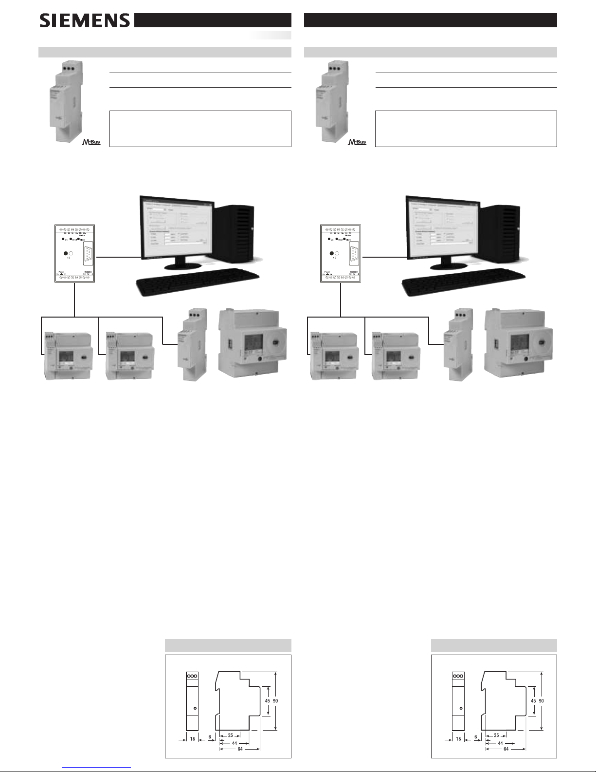
M-Bus Kommunikationsmodul
➟
➟
Messgerät
M-Bus
Kommunikationsmodul
M-Bus Gateway
(Stufen-Umschalter)
RS232/USB
M-Bus
M-Bus zweiadrige Bus-Leitung
seitliche Infrarot-Schnittstelle
! WARNUNG
Die Installation muss von einer Elektrofachkraft oder unter deren
Leitung und Aufsicht durchgeführt und geprüft werden.
Bedienungsanleitung
Kommunikationsmodul M-Bus - 1 TE
MLFB
Beschreibung
7KT1 908Kommunikationsmodul für den Anschluß an den M-Bus
für Energie- und Leistungsmessungen
M-Bus Interface
➟
➟
Measuring instrument
M-Bus
interface
M-Bus level converter
RS232/USB
M-Bus
M-Bus 2 wires bus
! WARNING
Installation must be carried out and inspected by a specialist
o
r under his supervision.
Operating instructions
Dimension
7KT1 908
M-Bus interface - 1 DIN module
Code Description
7KT1 908Module for M-Bus
connection for energy and power measurements
Maße
7KT1 908
Infrared lateral connection
800259-001
Stand 18-11-2009
D
EUTSCH
251428.41.28 “01”
E
NGLISH
M-Bus Kommunikationsmodul - Kurzanleitung
1) System Architektur
• Die nachfolgende Skizze zeigt eine mögliche Systemkonfiguration. In dieser Konfiguration
kommuniziert das M-Bus Kommunikationsmodul mit einer über PC verwalteten Masterstation
des Anwendungsprogramms.
2) Anschluss
• M-Bus: Die beiden Leiter an den Bus anschließen.
• Den Zähler neben dem M-Bus-Kommunikationsmodul positionieren; die IR-Fenster
müssen sich gegenüber liegen.
• Kabel:YCYM oder Standard-Telefonkabel J.Y(St)Y 2 x 2 x 0.8 mm.
3) Stromversorgung
• Die Stromversorgung erfolgt direkt über die Bus-Leitung. Die Verbindung ist von der Polarität
unabhängig.
•
Die Stromaufnahme einer M-Bus-Einheit beträgt < 2.6 mA (entsprechend zwei Standardlasten).
4) Default-Einstellungen
• Baudrate: 2400 bit/s
• Primarädresse M-Bus: 00
• Sekundäradresse M-Bus: siehe Klebeetikett auf dem Gehäuse der Schnittstelle
5) Download-Adresse für Software und Bedienungsanleitungen
http://www
.automation.siemens.com/et/beta/html_00/support/software-tools-
multizaehler
.htm
Software Unterlagen
• M-Bus Master-Anwendung • Bedienungsanleitung M-Bus Kommunikationsmodul
• Programm Data Analyzer • Bedienungsanleitung M-Bus Master-Anwendung
• Beschreibung des M-Bus Protokolls
•
Bedienungsanleitung des Programms Da
ta Analyser
6) Inbetriebnahme
•
Das K
ommunikationsmodul an die M-Bus-Leitung anschließen.
• Das M-Bus Kommunikationsmodul ist so neben dem Zähler zu positionieren,
dass die IR-Schnittstellen gegenüberliegen.
• Die M-Bus Master-Anwendung auf
dem PC installieren.
• Die M-Bus Master-Anwendung starten
und den weiteren
Anweisungen folgen.
7) Frontansicht
•
Eine grüne LED zeigt den Sta
tus der
Kommunikation zum Messgerät an:
- LED blinkt: keine Kommunikation
- LED leuchtet dauernd:
Kommunikation aktiv
M-Bus Interface Shorthand Guide
1) System Architecture
• One possible scheme of the system is described below. In the picture, the M-Bus interface
communicates with a remote master application on a PC.
2) Physical Connection
• M-Bus. Simply connect the M-Bus terminals to the two wires bus.
• IR lateral port: put the counter beside the M-Bus interface in a way that the interface IR port
face-up the counter IR port.
• Suitable cable: YCYM or standard telephone cable J.Y(St)Y 2 x 2 x 0.8 mm.
3) Supply
• The power supply is got directly from the bus.The connection is polarity independent.
• Current consumption of the M-Bus module < 2.6 mA (this is equivalent to two standard loads).
4) Default Setting
•
Baud ra
te:
2400 bit/s
• M-Bus Primary address: 00
• M-Bus secondary address: see the label stuck on the interface case
5) Download-Address for Software and User-Manual
http://www
.buildingtechnologies.siemens.com/bt/global/en/products_systems/ET/beta/
beta_support/subchannel-tools/Pages/software-multi-counters.aspx?rc=1
Software
Documentation
• M-Bus master application • M-Bus interface user guide
• Data analyzer tool • M-Bus master application user guide
• M-Bus protocol implementation reference manual
• Data analyzer tool user guide
6) Quick Start
• Connect the interface to the M-Bus line.
• Place the counter beside the interface in a way that the interface IR port face-up the
counter IR port.
• Install the M-Bus master application on a Windows PC.
• Run the M-Bus master application and follow the user guide indications.
7) Frontal Panel
• A green LED reports the state of the
communica
tion with the measuring
instrument:
- LED blinking: communication not active
- LED ON:
communica
tion active
Page 2
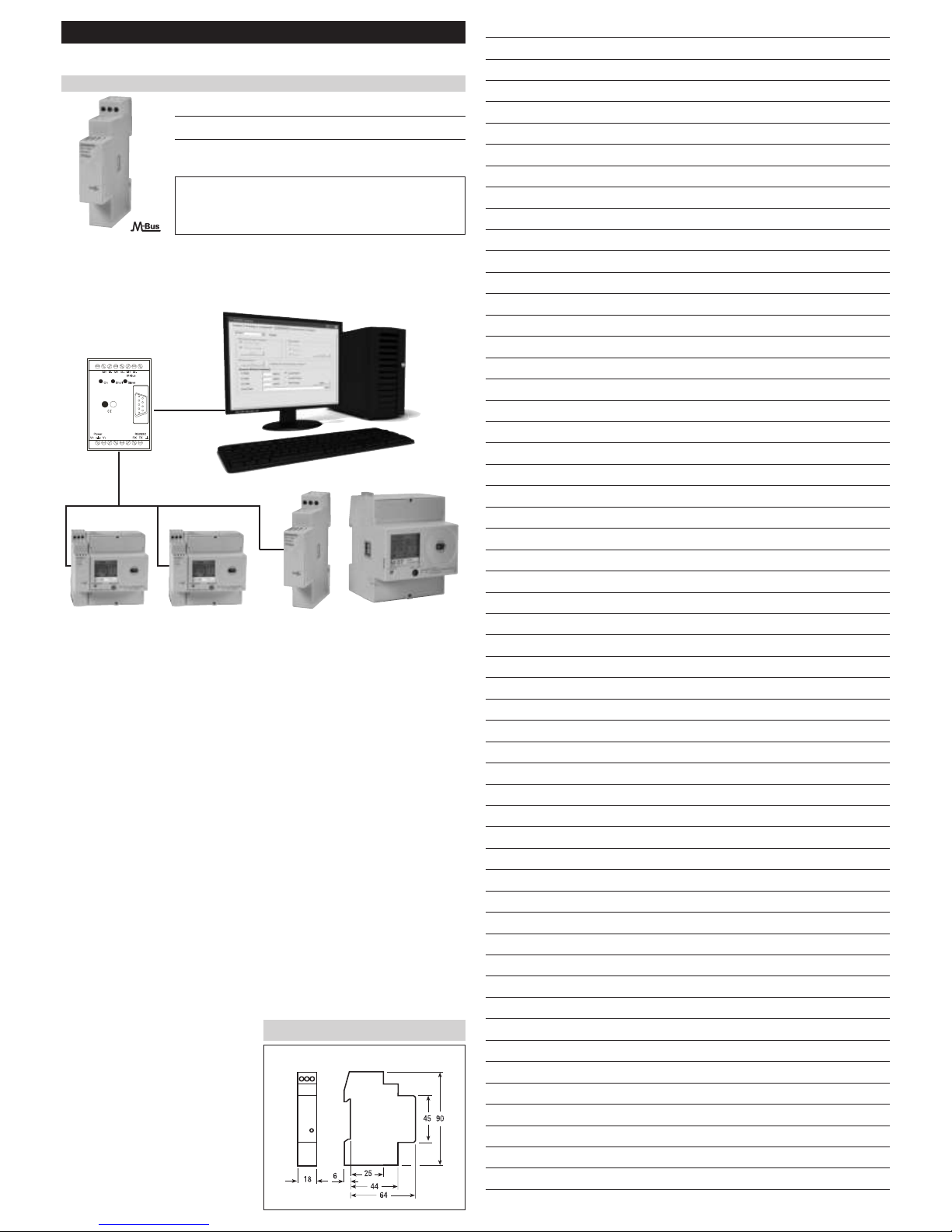
Interfaccia M-Bus
➟
➟
Strumento di
misura
Intefaccia
M-Bus
Convertitore
di livello M-Bus
RS232/USB
M-Bus
M-Bus a due fili
! ATTENZIONE
L’installazione deve essere effettuata e verificata da uno
s
pecialista o sotto la sua supervisione.
Istruzioni di servizio
Dimensioni
7KT1 908
Interfaccia M-Bus - 1 modulo DIN
Codice Descrizione
7KT1 908
M
odulo di comunicazione M-Bus
per la trasmissione di energia e potenza
Notizen -
Note
Collegamento infrarossi laterale
I
TALIANO
Interfaccia M-Bus - Guida Rapida
1) Architettura del Sistema
• Una possibile rappresentazione del sistema è descritta di seguito. Nella figura, l’interfaccia
M-Bus comunica con un’applicazione master remotizzata su un PC.
2) Connessione Fisica
• M-Bus. Collegare semplicemente i terminali ai due fili del bus.
• Porta IR laterale: posizionare il contatore accanto all’interfaccia M-Bus in modo che le rispettive
porte IR si fronteggino.
• Cavo: YCYM o cavo standard telefonico J.Y(St)Y 2 x 2 x 0.8 mm.
3) Alimentazione
• L’alimentazione è prelevata direttamente dal bus. La connessione è indipendente dalla polarità.
• Il consumo di corrente di un modulo M-Bus è < 2.6 mA (equivalente a due carichi standard).
4) Impostazione di Default
•
Baud ra
te:
2400 bit/s
• Indirizzo primario M-Bus: 00
• Indirizzo secondario M-Bus: consultare l’etichetta adesiva sul contenitore dell’interfaccia
5) Indirizzo per scaricare software e manuale utente
http://www
.buildingtechnologies.siemens.com/bt/global/en/products_systems/ET/beta/
beta_support/subchannel-tools/Pages/software-multi-counters.aspx?rc=1
Software
Documentazione
• Applicazione M-Bus master • Interfaccia M-Bus guida utente
• Programma Data analyzer • Applicazione master M-Bus guida utente
• Protocollo M-Bus manuale di riferimento
• Programma Data analyzer guida utente
6) Per Iniziare rapidamente
• Collegare l’interfaccia alla linea M-Bus.
• Posizionare il contatore accanto all’interfaccia M-Bus in modo che le rispettive porte IR
si fronteggino.
• Installare l’applicazione M-Bus master su un PC Windows.
• Lanciare l’applicazione M-Bus master e seguire le indicazioni della guida utente.
7) Pannello frontale
• Un LED verde rappresenta lo stato della
comunicazione con lo strumento di misura:
- LED lampeggiante comunicazione non attiva
- LED acceso fisso comunicazione attiva
Page 3
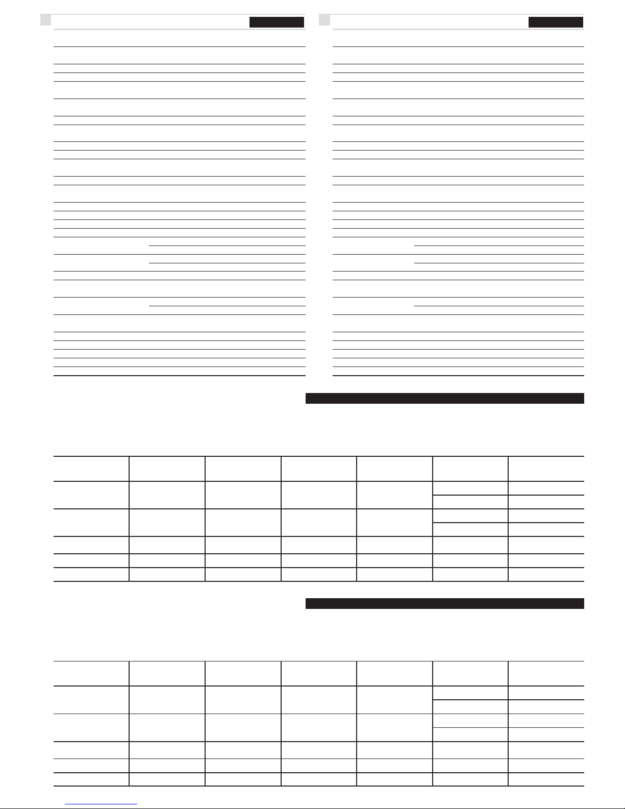
ITALIANO
D
ati tecnicI
ENGLISH
Secondo Norma EN13757-1-2-3, IEC 60950, EN 61000-6-2,
EN 61000-6-3 e EN 61000-4-2
Caratteristiche generali
• Custodia DIN 43880
• Fissaggio EN 60715
• Profondità
Alimentazione
• Alimentazione tramite bus
Funzionamento
• Modello disponibile:
trasmisione di dati su energia e potenza
- cod. 7KT1 908
• Utilizzabile sia con strumenti monofase che con strumenti trifase
Interfaccia M-Bus
• Interfaccia HW 2 morsetti a vite
• Protocollo SW M-Bus secondo EN1434
• Velocità di trasmissione
Interfaccia verso gli strumenti di misura
• Interfaccia HW ottica IR
• Protocollo SW
Sicurezza secondo EN 60950
• Grado di inquinamento
• Categoria di sovratensione
• Tensione di funzionamento
• Materiale custodia
• Distanza in aria
• Distanza superficiale dispositivo (apparecchio)
su PCB (non coperta)
• Tenuta all’impulso valore di picco dell’impulso (1,2/50 µs)
tensione di prova 50 Hz 1 min.
• Resistenza della custodia alla fiamma
Morsetti
• Tipo di gabbia testa della vite Z +/-
• Capacità morsetti filo compatto min. (max)
filo flessibile con capocorda min. (max)
Condizioni ambientali
• Temperatura di impiego
• Temperatura limite di immagazzinaggio
• Umidità relativa
• Vibrazioni ampiezza vibrazione sinusoidale a 50 Hz
• Classe di protezione secondo IEC 60950
• Grado di protezione apparecchio montato frontalmente
ENGLISH
T
echnical data
Data in compliance with EN13757-1-2-3, IEC 60950, EN 61000-6-2,
EN 61000-6-3 and EN 61000-4-2
General characteristics
• Housing DIN 43880
• Mounting EN 60715
• Depth
Power supply
• Power supply through bus connection
Operating features
• Model available:
for energy and power measur.
- code 7KT1 908
• Suitable for both single-phase and three-phase energy meters
M-Bus interface
• HW interface 2 screw clamps
• SW protocol M-Bus according to EN1434
• Baudrate Baud
Interface to measuring instrument
• HW interface optical IR
• SW protocol
Safety acc. to EN 60950
• Degree pollution
• Overvoltage category
• Working voltage
• Material group
• Clearance
• Creepage distance in equipment
on PCB (not coated)
• Test voltage impulse (1,2/50 µs) peak value
50 Hz 1 min
• Housing material flame resistance
Connection terminals
• Type cage screw head Z +/-
• Terminal capacity solid wire min. (max)
stranded wire with sleeve min. (max)
Environmental conditions
• Operating temperature
• Limit temperature of storage
• Relative humidity
• Vibrations sinusoidal vibration amplitude at 50 Hz
• Protection class acc.to IEC 60950
• Degree of protection housing when mounted in front
Cable length M-Bus according to EN13757-2 Annex E
Cable type:
• Shielded telephone cable 0,5 mm2(0,8 mm) (typ. 4x0,8 mm)
• NYM-cable (1,5 mm2)
Cable length:
Type Installation
Distance
(resistive cable
length)
Total Length
of segment wiring
Cable Type
(Diameter)
Number of Slaves
(Unit Loads)
max.
Baudrate
A
small in house
installation
350 m
1.000 m
(<30 Ohm)
0,5 mm
2
(0,8 mm)
250
64
9.600 Baud
38.400 Baud
B
large in house
installation
350 m
4.000 m
(<30 Ohm)
0,5 mm
2
(0,8 mm)
250
64
2.400 Baud
9.600 Baud
C
small wide area net
1.000 m
4.000 m (<90 Ohm)
0,5 mm
2
(0,8 mm)
64 2.400 Baud
D*
large wide area net
P
oint to Point
3.000 m
10.000 m
5.000 m
10.000 m
1,5 mm2(1,4 mm)
1,5 mm
2
(1,4 mm)
64
1
2.400 Baud
300 Baud
*
A special shielded calbe can be necessary!
!
Using telefone cables with an diameter of 0,6 mm either the max. length or the
number of slaves must be reduced by factor 2!
ITALIANO
La lunghezza del cavo M-Bus secondo EN13757-2 Allegato E
Tipo di cavo:
• Schermato cavo telefonico 0,5 mm2(0,8 mm) (tip. 4x0, 8 mm)
• Cavo-NYM (1,5 mm2)
Lunghezza cavo:
Tipo Impianto
Distanza
massima
Lunghezza
cavo totale
Sezione cavo
mm
2
Numero di
dispositivi
(Slaves)
Max. velocità di
trasmissione
A
edifici
residenziali piccoli
350 m
1.000 m
(<30 Ohm)
0,5 mm2(0,8 mm)
250
64
9.600 Baud
38.400 Baud
B
edifici
residenziali grandi
350 m
4.000 m
(<30 Ohm)
0,5 mm
2
(0,8 mm)
250
64
2.400 Baud
9.600 Baud
C
complessi piccoli
1.000 m
4.000 m (<90 Ohm)
0,5 mm
2
(0,8 mm)
64 2.400 Baud
D*
complessi grandi
collegam. punto-punto
3.000 m
10.000 m
5.000 m
10.000 m
1,5 mm
2
(1,4 mm)
1,5 mm
2
(1,4 mm)
64
1
2.400 Baud
300 Baud
* E’ neccessario usare un cavo speciale schermato!
!
Utilizzando cavi telefonici con un diametro di 0,6 mm max.
lunghezza o il numero di Slaves deve essere ridotto fattore 2!
Page 4
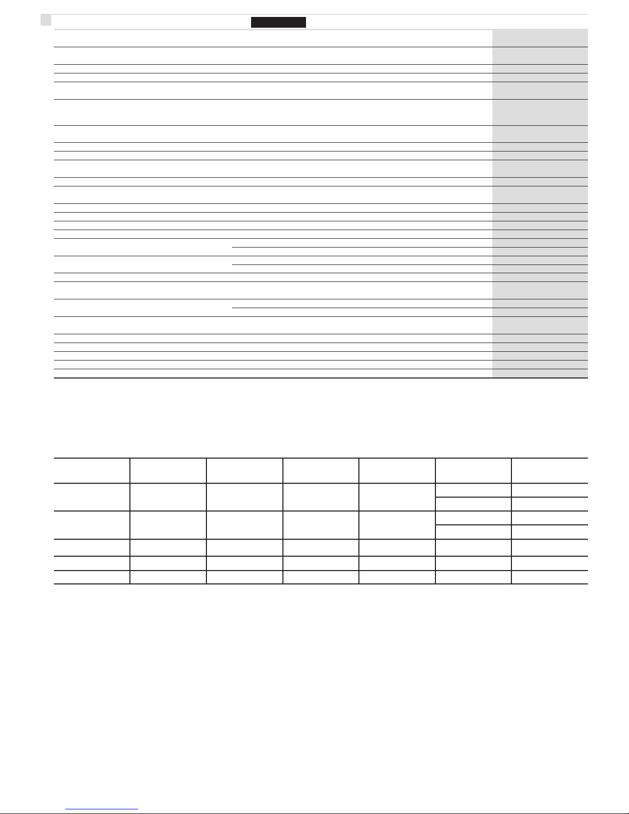
Daten nach EN13757-1-2-3, IEC 60950, EN 61000-6-2, EN 61000-6-3 und EN 61000-4-2 7KT1 908
Allgemeine Daten
• Gehäuse DIN 43880 DIN 1 Mod.
• Befestigung EN 60715 35 mm DIN Verteilerschiene
• Bauhöhe mm 70
Versorgung
• Steuerspannungsversorgung - über Bus
Betriebsarten
• Ausführungen: Datenübertragung
für Energie- und Leistungsmessungen
- MLFB 7KT1 908
• Einsatz mit einphasigen und dreiphasigen Meßinstrumenten - ja-yes-si
Schnittstelle M-Bus
• HW-Schnittstelle - 2 Schraubklemmen
• SW-Protokoll - M-Bus lt. EN1434
• Geschwindigkeit der Datenübertragung Baud 300 - 9600
Schnittstellen zu Meßinstrumente
• HW-Schnittstelle Infrarot - 2 (Tx, Rx)
• SW-Protokoll - eigen-proprietary-proprietario
Sicherheit nach IEC 60950
• Verschmutzungsgrad - 2
• Überspannungskategorie - II
• Betriebsspannung V d.c. 24 ... 36
• Gehäuse Material-Gruppe - II
• Luftstrecken mm !1.5
• Kriechstrecken im Gehäuse mm !2.1
auf Leiterplatten (ohne Schutzlack) mm !1.5
• Prüfstoßspannung 1,2/50 µs kV 2.5
50 Hz 1 min. kV 1.35
• Flammbeständigkeit UL 94 Klasse V0
Klemmen
• Schraubklemmen Schraubenkopf Z +/- POZIDRIV PZ1
• Leitungsquerschnitte starr min. (max) mm
2
0.15 (2.5)
flexibel, mit Hülse min. (max) mm
2
0.15 (4)
Umweltbedingungen
• Betriebstemperatur °C 0 ... +55
• Lagertemperatur °C -25 ... +70
• relative Luftfeuchte % "80
• Vibrationen Sinus-Amplitude bei 50 Hz mm ±0.25
• Schutzklasse nach IEC 60950 - II
• Schutzart Eingebautes Gerät Front - IP20
DEUTSCH
T
echnische Daten
Leitungslängen M-Bus nach EN13757-2 Anhang E
Kabelarten:
• geschirmte Telefonleitung 0,5 mm2(0,8 mm) (typ. 4x0,8 mm)
• NYM-Leitung (Standard-Elektroinstallationsleitung mit 1,5 mm2)
Leitungslängen:
Typ Anlage
max. Abstand zw.
2 Busteilnehmern
(resistive Länge)
max. Gesamtlänge
für ein Segment
Leitungsquerschnitt
(Durchmesser)
Anzahl der Slaves
(Unit Loads)
max.
Baudrate
A
kleine
Hausinstallation
350 m
1.000 m
(<30 Ohm)
0,5 mm
2
(0,8 mm)
250
64
9.600 Baud
38.400 Baud
B
große
Hausinstallation
350 m
4.000 m
(<30 Ohm)
0,5 mm
2
(0,8 mm)
250
64
2.400 Baud
9.600 Baud
C
kleine Wohnanlage
1.000 m
4.000 m (<90 Ohm)
0,5 mm
2
(0,8 mm)
64 2.400 Baud
D*
große Wohnanlage
Punkt zu Punkt
3.000 m
10.000 m
5.000 m
10.000 m
1,5 mm
2
(1,4 mm)
1,5 mm
2
(1,4 mm)
64
1
2.400 Baud
300 Baud
* Ein speziell geschirmtes Kabel kann erforderlich sein!
!
Bei Telefonleitungen mit 0,6 mm Durchmesser muss entweder die max.
Gesamtlänge oder die max. Anzahl der Geräte halbiert werden!
 Loading...