

Siemens 6SE7011-5EP60, 6SE7018-0EP60, 6SE7021-0EP60, 6SE7021-4EP60, 6SE7022-1EP60 Operating Instructions Manual
...Page 1

SIMOVERT MASTERDRIVES
Vector Control
Betriebsanleitung
Operating Instructions
Frequenzumrichter (AC-AC) Bauform Kompakt PLUS
Frequency Converter (AC-AC) Compact PLUS Type
Ausgabe / Edition: AB Bestell-Nr. / Order No.: 6S E7087-6JP60
Aotewell Ltd
www.aotewell.com
Industry Automation
HongKong|UK|China
sales@aotewell.com
+86-755-8660-6182
Page 2

Weitergabe sowie Vervielf äl tigung dieser Unterlage, Verwertung
und Mitteilung ihres Inhalts ni cht gestattet, soweit nicht ausdrücklich zugestanden. Zuwiderhandlungen verpflichten zu Schadenersatz. Alle Rechte vorbehalten, insbesondere für den Fall der
Patenterteilung oder GM-Eintragung.
Wir haben den Inhalt der Druckschrift auf Übereinstimmung mit der
beschriebenen Hard- und Software überprüft. Dennoch können
Abweichungen nicht ausgeschlossen werden, so daß wir für die
vollständige Übereinstimmung keine Garantie übernehmen. Di e
Angaben in dieser Druckschrift werden jedoch regelmäßig überprüft
und notwendige Korrekturen sind in den nachfolgenden Auflagen
enthalten. Für Verbesserungsvors chläge sind wir dankbar
SIMOVERT ist ein Warenzeichen von Siemens
The reproduction, transmission or use of this document or its contents is not permitted without express written authority. Off enders
will be liable for damages. All rights, including rights created by
patent grant or registration of a utility model or design, are
reserved.
We have checked the contents of this document to ensure that they
coincide with the described hardware and soft ware. However,
differences cannot be completely excluded, so that we do not
accept any guarantee for complete conformance. However, the
information in this document is regularly check ed and necessary
corrections will be included in subsequent editions. We are grateful
for any recommendations for improvement.
SIMOVERT Registered Trade Mark
Siemens AG 2001 All rights reserved
Diese Betriebsanleitung gilt für den Gerätesoftwarestand ab V3.32.
Änderungen von Funktionen, technischen Daten, Normen, Zeichnungen und Parametern vorbehalten.
These Operating Instructions are valid for software release from V3.32.
We reserve the right to make changes to functions, technical data, standards, drawings and parameters.
Aotewell Ltd
www.aotewell.com
Industry Automation
HongKong|UK|China
sales@aotewell.com
+86-755-8660-6182
Page 3

05.2003 Contents
Siemens AG 6SE7087-6JP60
SIMOVERT MASTERDRIVES Operating Instructions 1
Contents
1 DEFINITIONS AND WARNINGS .....................................................................1-1
2 DESCRIPTION..................................................................................................2-1
3 FIRST START-UP.............................................................................................3-1
4 TRANSPORT, STORAGE, UNPACKING........................................................4-1
5 INSTALLATION................................................................................................5-1
5.1 Installing the units .............................................................................................5-1
5.2 Installing the optional boards ............................................................................5-4
5.2.1 Installing optional boards on units with a width up to 90 mm ...........................5-4
5.2.2 Installing optional boards on units with a width of 135 mm and 180 mm .........5-7
6 INSTALLATION IN CONFORMANCE WITH EMC REGULATIONS ..............6-1
7 CONNECTING-UP............................................................................................7-1
7.1 Power connections............................................................................................7-5
7.1.1 Power connections for units with a width up to 90 mm.....................................7-5
7.1.2 Power connections for units with a width of 135 mm........................................7-8
7.1.3 Power connections for units with a width of 180 mm......................................7-10
7.2 Control connections ........................................................................................7-12
7.3 Conductor cross-sections, fuses, reactors......................................................7-22
7.4 Combinations of units......................................................................................7-23
8 PARAMETERIZATION.....................................................................................8-1
8.1 Parameter menus..............................................................................................8-1
8.2 Changeability of parameters.............................................................................8-5
Aotewell Ltd
www.aotewell.com
Industry Automation
HongKong|UK|China
sales@aotewell.com
+86-755-8660-6182
Page 4

Contents 05.2003
6SE7087-6JP60 Siemens AG
2 Operating Instructions SIMOVERT MASTERDRIVES
8.3 Parameter input with DriveMonitor....................................................................8-6
8.3.1 Installation and connection ...............................................................................8-6
8.3.1.1 Installation.........................................................................................................8-6
8.3.1.2 Connection........................................................................................................8-6
8.3.2 Drive configuration DriveMonitor.......................................................................8-7
8.3.2.1 Setting the interface ..........................................................................................8-9
8.3.2.2 Drive settings ..................................................................................................8-10
8.3.3 Parameterization.............................................................................................8-15
8.3.3.1 Structure of the parameter lists, parameterization with DriveMonitor.............8-15
8.3.3.2 Diagnostic menu .............................................................................................8-16
8.4 Parameter input via the PMU..........................................................................8-17
8.5 Parameter input via the OP1S ........................................................................8-21
8.5.1 General............................................................................................................8-21
8.5.2 Connecting, run-up..........................................................................................8-23
8.5.2.1 Connecting......................................................................................................8-23
8.5.2.2 Run-up.............................................................................................................8-24
9 PARAMETERIZING STEPS.............................................................................9-1
9.1 Parameter reset to factory setting.....................................................................9-2
9.2 Power section definition ....................................................................................9-4
9.2.1 Parameterizing with parameter modules (quick parameterization, P060 = 3)..9-5
10 MAINTENANCE..............................................................................................10-1
10.1 Replacing the fan ............................................................................................10-1
10.1.1 Replacing the fan in units up to 45 mm wide..................................................10-2
10.1.2 Replacing the fan in units up to 90 mm wide..................................................10-2
10.1.3 Replacing the fan in units 135 mm wide.........................................................10-3
10.1.4 Replacing the fan in units up to 180 mm wide................................................10-3
11 FORMING .......................................................................................................11-1
12 TECHNICAL DATA ........................................................................................12-1
13 FAULTS AND ALARMS.................................................................................13-1
13.1 Faults...............................................................................................................13-1
13.2 Alarms...........................................................................................................13-18
13.3 Fatal errors (FF)............................................................................................13-27
14 ENVIRONMENTAL FRIENDLINESS .............................................................14-1
Aotewell Ltd
www.aotewell.com
Industry Automation
HongKong|UK|China
sales@aotewell.com
+86-755-8660-6182
Page 5

10.2001 Definitions and Warnings
Siemens AG 6SE7087-6JP60
SIMOVERT MASTERDRIVES Operating Instructions 1-1
1 Definitions and Warnings
For the purpose of this documentation and the product warning labels,
a "Qualified person" is someone who is familiar with the installation,
mounting, start-up, operation and maintenance of the product. He or
she must have the following qualifications:
♦ Trained or authorized to energize, de-energize, ground and tag
circuits and equipment in accordance with established safety
procedures.
♦ Trained or authorized in the proper care and use of protective
equipment in accordance with established safety procedures.
♦ Trained in rendering first aid.
indicates an imminently hazardous situation which, if not avoided, will
result in death, serious injury and considerable damage to property.
indicates a potentially hazardous situation which, if not avoided, could
result in death, serious injury and considerable damage to property.
used with the safety alert symbol indicates a potentially hazardous
situation which, if not avoided, may result in minor or moderate injury.
used without safety alert symbol indicates a potentially hazardous
situation which, if not avoided, may result in property damage.
NOTICE used without the safety alert symbol indicates a potential
situation which, if not avoided, may result in an undesirable result or
state.
For the purpose of this documentation, "Note" indicates important
information about the product or about the respective part of the
documentation which is essenti al to highl ight.
Qualified personnel
DANGER
WARNING
CAUTION
CAUTION
NOTICE
NOTE
Aotewell Ltd
www.aotewell.com
Industry Automation
HongKong|UK|China
sales@aotewell.com
+86-755-8660-6182
Page 6

Definitions and Warnings 10.2001
6SE7087-6JP60 Siemens AG
1-2 Operating Instructions SIMOVERT MASTERDRIVES
Hazardous voltages are present in this elec tric al equ ipment during
operation.
Non-observance of the warnings can thus result in severe personal
injury or property damage.
Only qualified personnel should work on or around the equipment
This personnel must be thoroughly familiar with all warning and
maintenance procedures contained in this documentation.
The successful and safe operation of this equipment is dependent on
correct transport, proper storage and ins ta l lat ion as well as caref ul
operation and maintenance.
This documentation does not purport to cover all details on all types of
the product, nor to provide for every possible contingency to be met in
connection with installation, operation or maintenance.
Should further information be desired or should particular problems
arise which are not covered sufficiently for the purchaser's purposes,
the matter should be referred to the local SIEMENS sales office.
The contents of this documentation shall not become part of or modify
any prior or existing agreement, commitment or relationship. The sales
contract contains the entire obligation of SIEMENS AG. The warranty
contained in the contract between the parties is the sole warranty of
SIEMENS AG. Any statements contained herein do not create new
warranties or modify the existing warranty.
WARNING
NOTE
Aotewell Ltd
www.aotewell.com
Industry Automation
HongKong|UK|China
sales@aotewell.com
+86-755-8660-6182
Page 7
10.2001 Definitions and Warnings
Siemens AG 6SE7087-6JP60
SIMOVERT MASTERDRIVES Operating Instructions 1-3
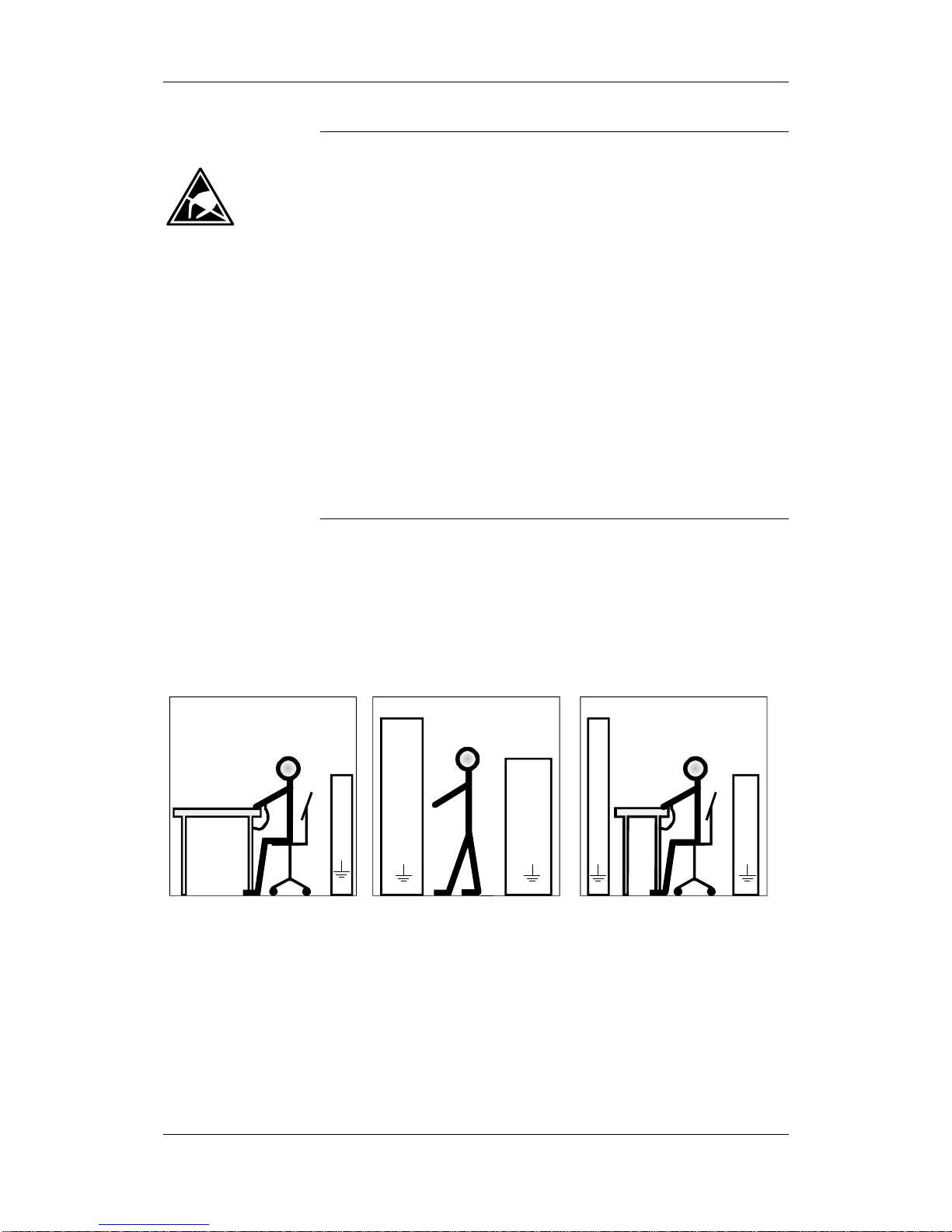
Components which can be destro yed by electros tatic disc har g e (ESD)
The board contains components which can be destroyed by
electrostatic discharge. These components can be easily destroyed if
not carefully handled. If you have to handle elec tr onic boar ds, pl eas e
observe the following:
Electronic boards should only be touched when absolutely necessary.
The human body must be electrically discharged before touching an
electronic board.
Boards must not come into contact with highly insulating materials - e.g.
plastic parts, insulated desktops, articles of clothing manufactured from
man-made fibers.
Boards must only be placed on conductive surfaces.
Boards and components should only be stored and transported in
conductive packaging (e.g. metalized plastic boxes or metal
containers).
If the packing material is not conductive, the boards must be wrapped
with a conductive packaging material, e.g. conductive foam rubber or
household aluminium foil.
The necessary ESD protective measures are clearly shown again in the
following diagram:
♦ a = Conductive floor surface
♦ b = ESD table
♦ c = ESD shoes
♦ d = ESD overall
♦ e = ESD chain
♦ f = Cubicle ground connection
StandingSitting Standin g / Sit ti ng
a
b
e
d
c
d
a
c
d
b
c
a
e
f
f
f f f
Fig. 1-1 ESD protective measures
CAUTION
Aotewell Ltd
www.aotewell.com
Industry Automation
HongKong|UK|China
sales@aotewell.com
+86-755-8660-6182
Page 8

Definitions and Warnings 10.2001
6SE7087-6JP60 Siemens AG
1-4 Operating Instructions SIMOVERT MASTERDRIVES
Safety and Operating Instructions
for Drive Converters
(in conformity with the low-voltage directive 73/23/EEC)
1. General
In operation, drive converters, depending on thei r degree
of protection, may have live, uninsulated, and possibly
also moving or rotating parts, as well as hot surfaces.
In case of inadmissible removal of the required covers, of
improper use, wrong installation or maloperation, t here is
the danger of serious personal injury and damage to
property.
For further information, see documentation.
All operations serving transport, installation and
commissioning as well as maintenance are to be carried
out by skilled technical personnel (observe IEC 364 or
CENELEC HD 384 or DIN VDE 0100 and IEC Report
664 or DIN VDE 0110 and national accident prevention
rules).
For the purposes of these basic safety instructions,
"skilled technical personnel" means persons who are
familiar with the installation, mounting, commissioning
and operation of the product and have the qualifications
needed for the performance of their functions.
2. Intended use
Drive converters are components designed for inclusion
in electrical installations or machinery.
In case of installation in machinery, commissioning of the
drive converter (i.e. the starting of normal operation) is
prohibited until the machinery has been proved to
conform to the provisions of the EC directive 89/392/EEC
(Machinery Safety Directive - MSD). Account is to be
taken of EN 60204.
Commissioning (i.e. the start of normal operation) is
admissible only where conformity with the EMC directive
(89/336/EEC) has been established.
The drive converters meet the requirements of the lowvoltage directive 73/23/EEC. They are subject to the
harmonized standards of the series prEN 50178/DIN
VDE 0160 in conjunction with EN 60439-1/DIN VDE
0660 Part 500 and EN 60146/DIN VDE 0558.
The technical data as well as information concerning t he
supply conditions shall be taken from the rating plate and
from the documentation and shall be strictly observed.
3. Transport, storage
The instructions for transport, storage and proper use
shall be complied with.
The climatic conditions shall be in conformity with prEN
50178.
4. Installation
The installation and cooling of the appliances shall be in
accordance with the specifications in the pertinent
documentation.
The drive converters shall be protected against
excessive strains. In particular, no components must be
bent and/or isolating distances altered in the course of
transportation or handling. No contact shall be made with
electronic components and contacts.
Drive converters contain electrostatic sensitive
components which are liable to damage through
improper use. Electronic components must not be
mechanically damaged or destroyed (potential health
risks).
5. Electrical connection
When working on live drive converters, the applicable
national accident prevention rules (e.g. VBG 4) must be
complied with.
The electrical installation shall be carried out in
accordance with the relevant requirements (e.g. crosssectional areas of conductors, fusing, PE connection).
For further information, see documentation.
Instructions for the installation in accordance with EMC
requirements, such as screening, grounding, location of
filters and wiring, are contained in the drive converter
documentation. They must always be complied with, also
for drive converters bearing a CE marking. Observance
of the limit values required by the EMC law is the
responsibility of the manufacturer of the installation or
machine.
6. Operation
Installations which include drive converters shall be
equipped with additional monitoring and protective
devices in accordance with the relevant applicable s afet y
requirements, e.g. Act respecting technical equipment,
accident prevention rules, etc. Changes to the drive
converters by means of the operating software are
permissible.
After disconnection of the drive converters from the
voltage supply, live appliance parts and power terminals
must not be touched immediately because of possibly
energized capacitors. In this regard, the corresponding
signs and markings on the drive converter must be
respected.
During operation, all covers and doors shall be kept
closed.
7. Maintenance and servicing
The manufacturer's documentation shall be followed.
Keep these safety instructions in a safe place!
Aotewell Ltd
www.aotewell.com
Industry Automation
HongKong|UK|China
sales@aotewell.com
+86-755-8660-6182
Page 9
05.2003 Description
Siemens AG 6SE7087-6JP60
SIMOVERT MASTERDRIVES Operating Instructions 2-1
2 Description
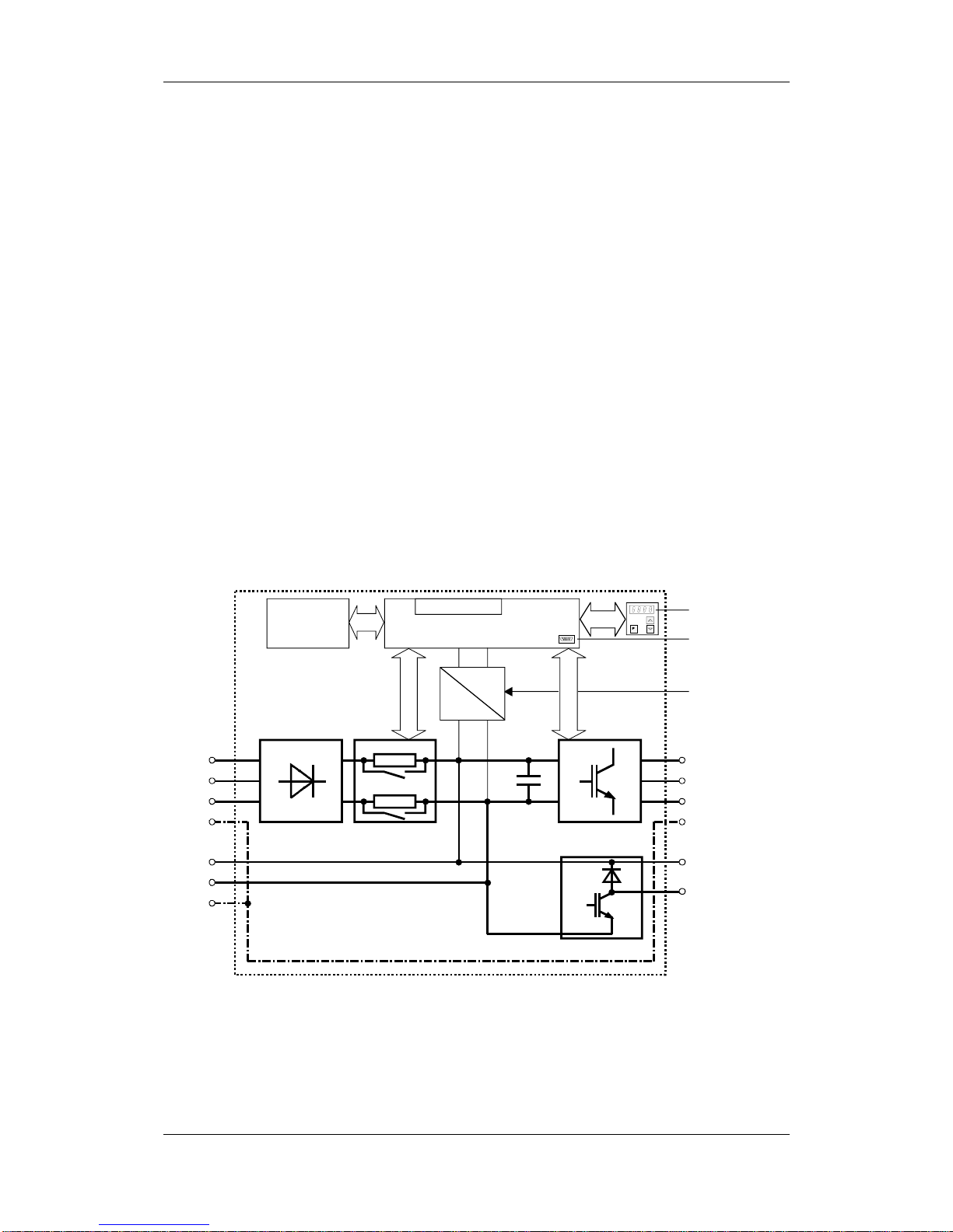
The converters are power electronics components for feeding threephase motors.
They can be operated from a three-phase system with a voltage
between 380 V and 480 V and a frequency of 50/60 Hz.
The line voltage from the system is rectified and fed into the DC link.
The power section enables a three-phase system with a variable output
frequency between 0 Hz and 500 Hz maximum to be generated from
the DC link direct voltage with the pulse width modulation method
(PWM).
The internal DC 24 V voltage is supplied through an integral power
supply unit.
The unit is controlled by the internal control electronics which consists
of a microprocessor system. The functions are provided by the unit
software.
Operator control is effected via the PMU operator control panel, the
user-friendly OP1S operator control panel, the terminal strip or via a
bus system. For this purpose, the unit has a number of interfaces and
two slots for the use of optional boards.
Pulse encoders can be used as motor-specific encoders.
Motor
connection
U2/T1
V2/T2
W2/T3
PE2
Cont rol electronics
Serial
interface
Terminal strip
Optional
boards
DC link
U1/L1
V1/L2
W1/L3
PE1
PMU
InverterPrechargingRectifier
Internal
power
supply
G
H
Braking
resistor
24 V
==
==
Brake choppe r
C / L+
D / L PE3
-X9
external DC 24 V
supply
Fig. 2-1 Circuit principle of the frequency converter
Range of application
Aotewell Ltd
www.aotewell.com
Industry Automation
HongKong|UK|China
sales@aotewell.com
+86-755-8660-6182
Page 10
10.2001 First Start-up
Siemens AG 6SE7087-6JP60
SIMOVERT MASTERDRIVES Operating Instructions 3-1
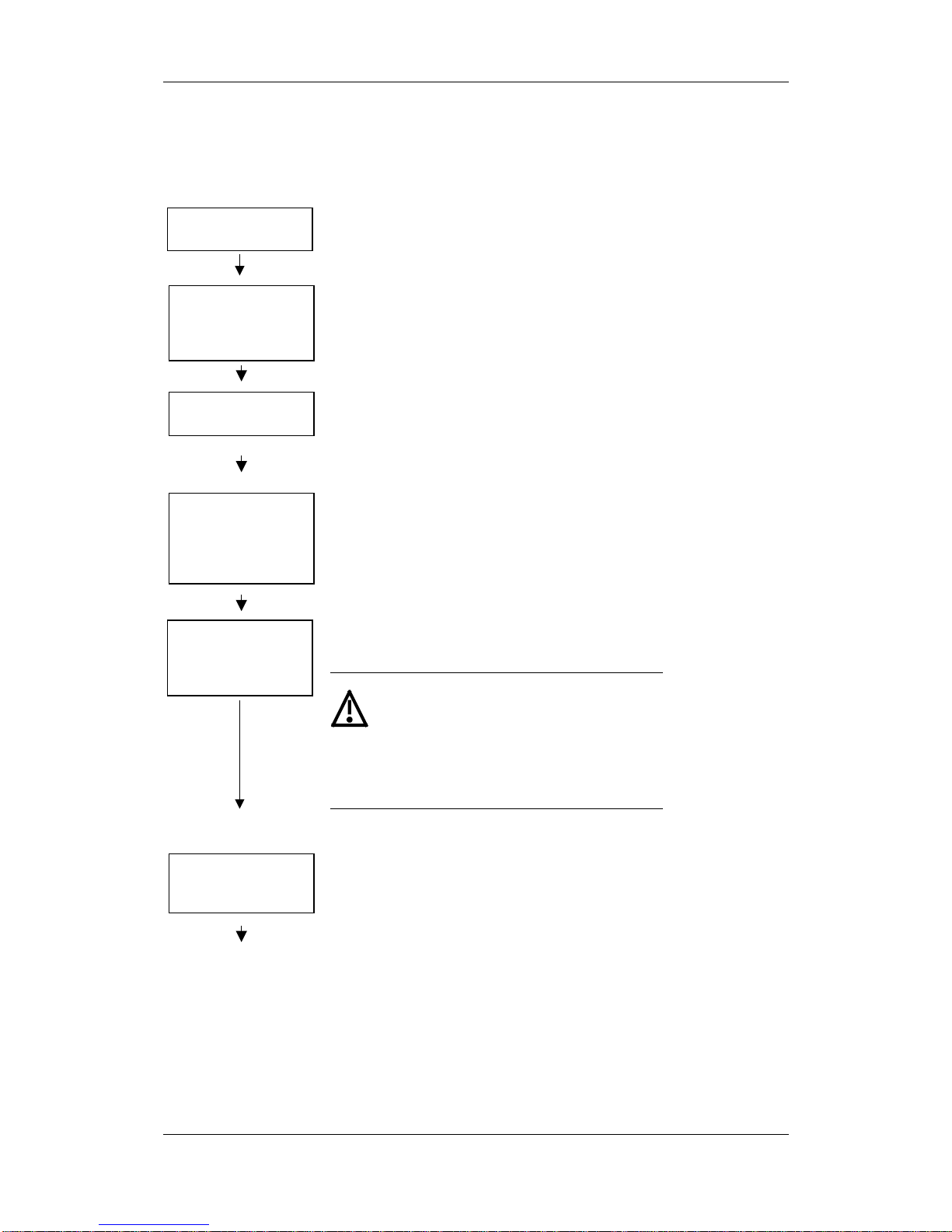
3 First Start-up
After removing the packaging, check that the unit is
intact and undamaged. Only intact units may be started
up. Please also check that the unit is complete and that
the correct optional boards are fitted.
Unpack and check the
units
See section
"Transport,
Storage,
Unpacking"
Retrofit any optional boards which have not yet been
installed, if necessary. Then install the units taking into
account the requirements at the point of installation and
the EMC instructions.
Mount the unit and
install optional boards
which have not yet
been fitted
See section
"Installation"
and "Installation
in Conformance
with EMC
Regulations"
If the DC link of the unit was de-energized for more than
one year, you have to newly form the DC link capacitors
Form the DC link
capacitors, if necessary
See section
"Forming"
Please connect, starting with the protective conductor,
the power cables or DC link buses and, if present, the
external 24 V supply. Pay attention to EMC instructions
when laying the cables. Please do not at this stage
connect any control, communication, encoder and motor
cables (exception: cable for connecting up an OP1S, if
parameterization is to be effected via the OP1S).
Connect the protective
conductor, the power
cables or buses and, if
present, the ext. 24 V
supply
See section
"Connecting-up"
and
"Installation in
Conformance
with EMC
Regulations"
Please connect the remaining control, communication,
encoder and motor cables. Pay attention to the EMC
instructions when laying the cables.
Connect the control
cables, communication
cables, encoder cables
and motor cables
See section
"Connecting-up"
and "Installation
in Conformance
with EMC
Regulations"
WARNING
The device must be
disconnected
from
its voltage supplies (24 V DC electronics
supply
and
DC link / mains voltage)
before the control and encoder leads are
connected or disconnected!
Failure to observe this advice can result in
encoder defects, which may in turn cause
uncontrolled axis movements.
After checking that the cabling has been correctly
connected and that it sits properly, power up the
external 24 V supply or the line voltage. After the
electronics power supply has been started, the unit
initializes itself. The action can take several seconds.
The drive status is subsequently shown on the PMU.
Power up the external
24 V supply or the line
voltage
111
Aotewell Ltd
www.aotewell.com
Industry Automation
HongKong|UK|China
sales@aotewell.com
+86-755-8660-6182
Page 11
First Start-up 10.2001
6SE7087-6JP60 Siemens AG
3-2 Operating Instructions SIMOVERT MASTERDRIVES
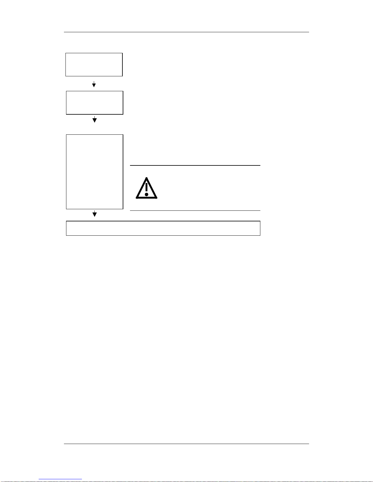
If the PMU does not show status °009 after completion
of the unit initialization, or if the unit has already been
parameterized before, you should carry out a parameter
reset to factory setting.
If necessary, carry out
parameter reset to
factory setting
See section
"Parameterization"
AAA
Parameterizing by
download or with
parameter modules
See section
"Parameterization"
After checking the unit and the cabling once more,
power up the line voltage or DC bus voltage, if you have
not already done so, and perform a function test
according to your parameterization.
Function test
siehe
"Anschließen"
und "EMV-
gerechter
Aufbau"
It must be ensured that no danger for
persons and equipment can occur by
energizing the power and the unit. It is
recommended not to couple the driven
machine until the function test has
been successfully completed.
WARNING
Further start-up and parameterization according to
your specific requirements
siehe "Ans
Aotewell Ltd
www.aotewell.com
Industry Automation
HongKong|UK|China
sales@aotewell.com
+86-755-8660-6182
Page 12

10.2001 Transport, Storage, Unpacking
Siemens AG 6SE7087-6JP60
SIMOVERT MASTERDRIVES Operating Instructions 4-1
4 T ran sport, Storage, Unp acking
The units and components are packed in the manufacturing plant
corresponding to that specified when ordered. A packing label is
located on the outside of the packaging. Please observe the
instructions on the packaging for transport, storage and professional
handling.
Vibrations and jolts must be avoided during transport. If the unit is
damaged, you must inform your shipping company immediately.
The units and components must be stored in clean, dry rooms.
Temperatures between -25 °C (-13 °F) and +70 °C (158 °F) are
permissible. Temperature fluctuations must not be more than 30 K per
hour.
If the storage period of one year is exceeded, the unit must be newly
formed. See Section ”Forming".
The packaging comprises board and corrugated paper. It can be
disposed of corresponding to the appropriate local regulations for the
disposal of board products. The units and components can be installed
and commissioned after they have been unpacked and checked to
ensure that everything is complete and that they are not damaged.
Transport
Storage
CAUTION
Unpacking
Aotewell Ltd
www.aotewell.com
Industry Automation
HongKong|UK|China
sales@aotewell.com
+86-755-8660-6182
Page 13

05.2003 Installation
Siemens AG 6SE7087-6JP60
SIMOVERT MASTERDRIVES Operating Instructions 5-1
5 Installation
5.1 Installing the units
Safe converter operation requires that the equipment is mounted and
commissioned by qualified personnel taking into account the warning
information provided in these Operating Instructions.
The general and domestic installation and safety regulations for work
on electrical power equipment (e.g. VDE) must be observed as well as
the professional handling of tools and the use of personal protective
equipment.
Death, severe bodily injury or significant material damage could result if
these instructions are not followed.
When installing the units, make sure that the mains connection is
located at the top section and the motor connection at the lower section
of the unit.
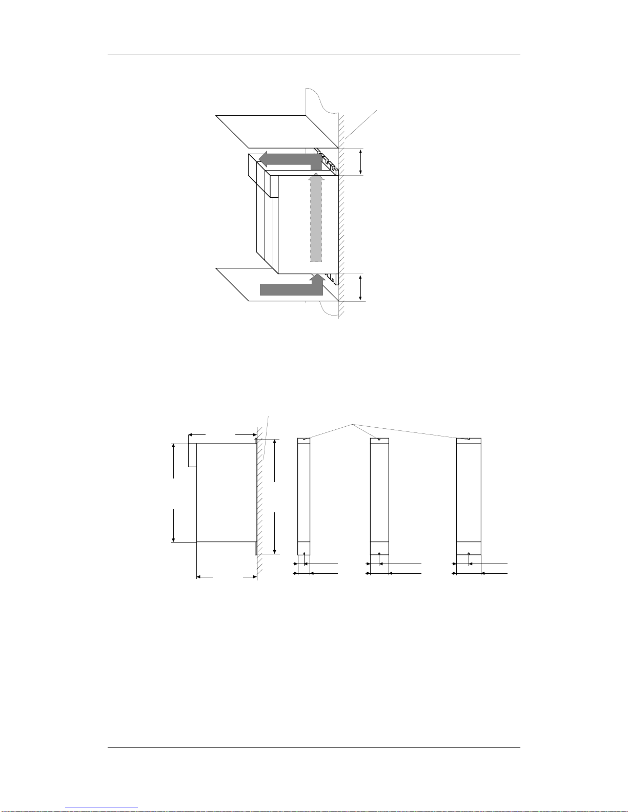
The units can be mounted flush with each other.
In order to ensure an adequate supply of cooling air, a clearance of
100 mm must be left at the top of the unit and at the bottom of the unit
respectively to components which may considerably affect the flow of
cooling air.
When mounting in cabinets, the cabinet cooling must be designed
according to the power loss. Please refer to the Technical Data in this
regard.
♦ Foreign particles
The units must be protected against the ingress of foreign particles
as otherwise their function and operational safety cannot be
ensured.
♦ Dust, gases, vapors
Equipment rooms must be dry and dust-free. Ambient and cooling
air must not contain any electrically conductive gases, vapors and
dust which could diminish the functionality. If necessary, filters
should be used or other corrective measures taken.
♦ Cooling air
The units must only be operated in an ambient climate in
accordance with DIN IEC 721-3-3 Class 3K3. For cooling air
temperatures of more than 45 °C (113 °F) and installation altitudes
higher than 1000 m, derating is required.
WARNING
Clearances
Requirements at the
point of installation
Aotewell Ltd
www.aotewell.com
Industry Automation
HongKong|UK|China
sales@aotewell.com
+86-755-8660-6182
Page 14
Installation 05.2003
6SE7087-6JP60 Siemens AG
5-2 Operating Instructions SIMOVERT MASTERDRIVES
Mounting
surface
100 mm
100 mm
Cooling air
Fig. 5-1 Minimum clearances for cooling
The unit is mounted directly to a mounting surface. Fixing is by means
of two or four M5 screws.
Side view Front view (without front panel)
22.5 mm
220 mm
360 mm
Mounting surface
Cutouts
for M5 screws
414 mm
45 mm
250 mm
33.75 mm
67.5 mm
45 mm
90 mm
0.55 kW 1.1 / 1.5 kW 3.0 / 4.0 kW
Fig. 5-2 Dimension drawings for housings up to 90 mm wide
Installation
Aotewell Ltd
www.aotewell.com
Industry Automation
HongKong|UK|China
sales@aotewell.com
+86-755-8660-6182
Page 15
05.2003 Installation
Siemens AG 6SE7087-6JP60
SIMOVERT MASTERDRIVES Operating Instructions 5-3
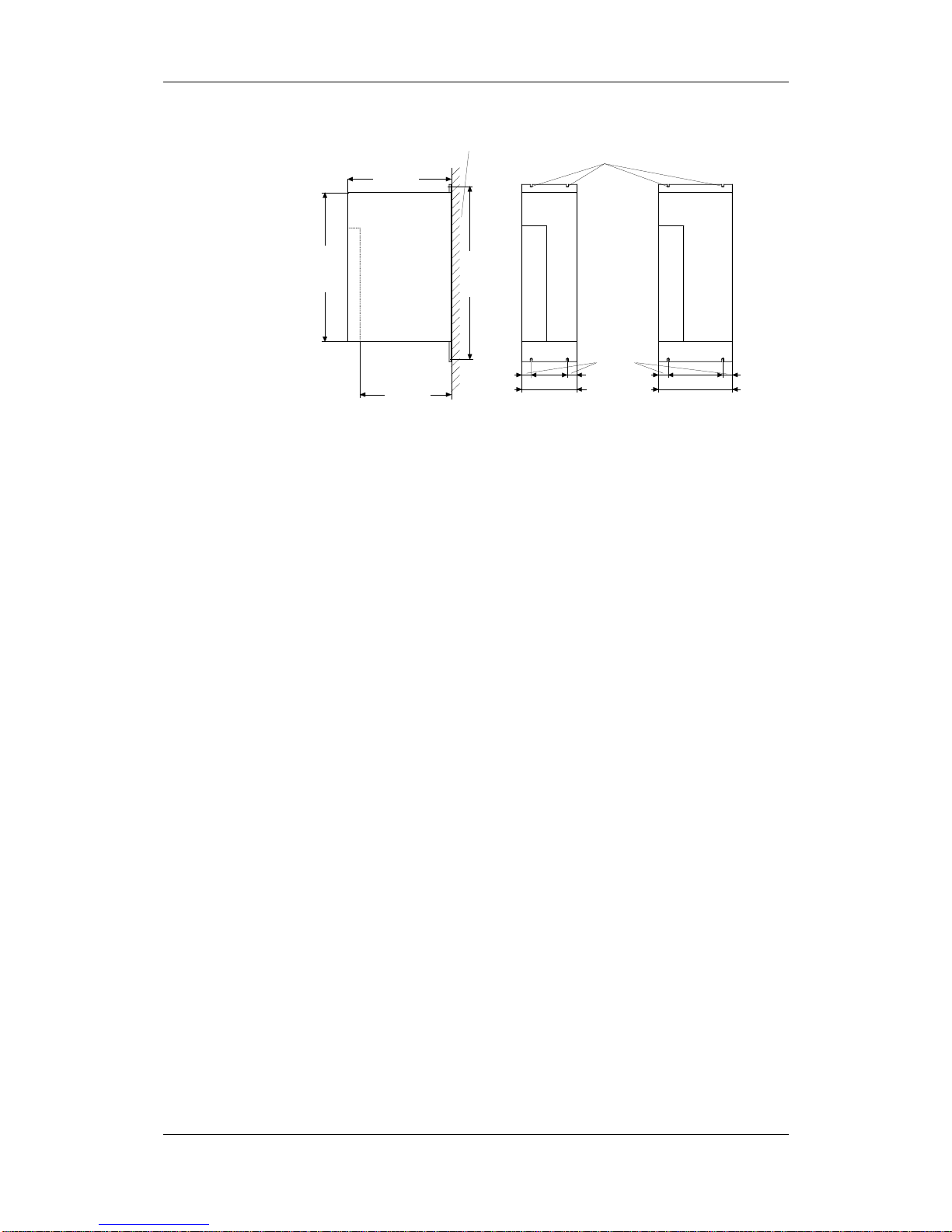
Side view Front view
22.5 mm
220 mm
360 mm
Mounting surface
Cutouts
for M5 screws
414 mm
135 mm
250 mm
5.5 / 7.5 kW
180 mm
11 / 15 kW
Fig. 5-3 Dimension drawings for housings 135 mm and 180 mm wide
Aotewell Ltd
www.aotewell.com
Industry Automation
HongKong|UK|China
sales@aotewell.com
+86-755-8660-6182
Page 16

Installation 05.2003
6SE7087-6JP60 Siemens AG
5-4 Operating Instructions SIMOVERT MASTERDRIVES
5.2 Installing the optional boards
The unit has hazardous voltage levels up to 5 minutes after it has been
powered down due to the DC link capacitors. The unit or the DC link
terminals must not be worked on until at least after this delay time.
5.2.1 Installing optional boards on units with a width up to 90 mm
Disconnecting the unit from the supply
Disconnect the unit from the power supply and power down the unit.
Remove the 24 V voltage supply for the electronics. Remove all
connecting cables.
Dismantle the unit as follows:
♦ Open the terminals of the DC link bus module.
♦ Remove the fixing screws by means of which the unit is fixed to the
mounting surface.
♦ Pull the unit down until the DC link bus module is completely
exposed.
♦ Pull the unit out towards you.
♦ Lay the unit on its left side.
If you are using an AC unit as a single drive, there is no DC link bus
module. You can then withdraw the unit directly after removing the
fixing screws.
♦ Unscrew the two fixing screws of the right-hand side wall. The fixing
screws are located at the top of the unit at the rear right-hand
corner, and at the bottom of the unit in the middle of the right-hand
side wall.
♦ You do not have to remove the two fixing screws completely, as the
wall of the unit is provided with a cutout to enable you to swing out
the cover once the screws have been loosened.
♦ Open the right-hand side wall. To open it, swing the right-hand side
wall towards you and pull it upwards out of the guide on the front
edge.
♦ Remove the cover of the selected slot on the front panel.
♦ To do so, you must carefully cut through the four connecting points
of the cover on the front panel with a thin knife.
DANGER
DANGER
Dismantling the unit
Opening the unit
Removing the slot
cover
Aotewell Ltd
www.aotewell.com
Industry Automation
HongKong|UK|China
sales@aotewell.com
+86-755-8660-6182
Page 17
05.2003 Installation
Siemens AG 6SE7087-6JP60
SIMOVERT MASTERDRIVES Operating Instructions 5-5
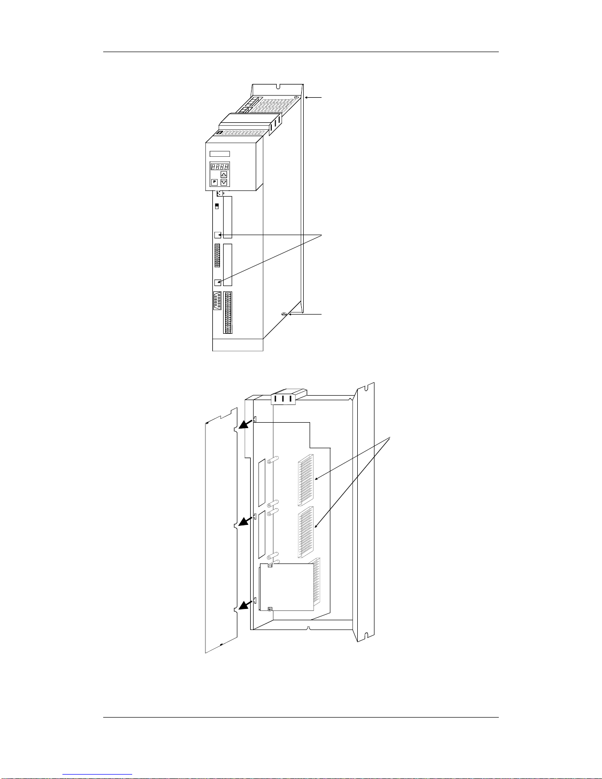
SIEMENS
A
S1
BX101
CX103
Fixing screw for side
cover
Fixing screw for
side cover
Designation plates
for the optional
boards
Fig. 5-4 Position of the fixing screws on the right-hand side wall
Slot A
Slot B
Slot C
Rear wall
Slots for optional
boards
Right-han d side wall open
CU
PBI
Fig. 5-5 Removing the right-hand side wall
Aotewell Ltd
www.aotewell.com
Industry Automation
HongKong|UK|China
sales@aotewell.com
+86-755-8660-6182
Page 18
Installation 05.2003
6SE7087-6JP60 Siemens AG
5-6 Operating Instructions SIMOVERT MASTERDRIVES
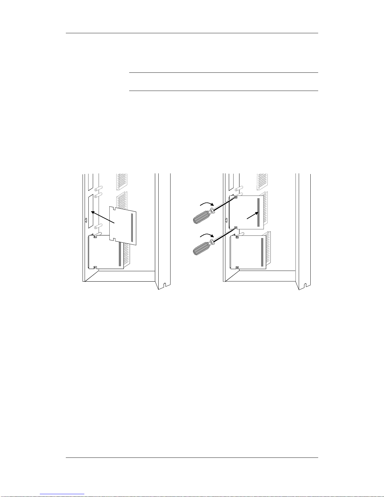
Optional boards can only be inserted in slot A and slot B. Slot C of the
unit is permanently pre-assigned for the terminal module EBV.
Push the optional board from behind into the opening on the front cover
(
) until the position of the 64-pole system connector on the main
board corresponds with the position of the socket.
Insert the optional board from the right onto the 64-pole system
connector on the main board (
). The view shows the installed state.
Screw the optional board tight at the fastening points in the front section
of the optional board (
).
Slot A
Slot B
Slot B
Rear wall
Slot A
Slot C
Slot C
Rear wall
Fig. 5-6 Installing the optional board
Installing the
optional board
NOTICE
Aotewell Ltd
www.aotewell.com
Industry Automation
HongKong|UK|China
sales@aotewell.com
+86-755-8660-6182
Page 19

05.2003 Installation
Siemens AG 6SE7087-6JP60
SIMOVERT MASTERDRIVES Operating Instructions 5-7
Close the right-hand side wall of the unit as follows
♦ Insert the right-hand side wall from above into the guide on the front
right-hand side.
♦ Swing back the side wall.
♦ Screw the side wall tight again by means of the two fixing screws.
Mount the unit as follows:
♦ Insert the unit into its mounting position from the front underneath
the DC link bus module.
♦ Lift the unit upwards until the DC link bus module is completely in its
original position again.
♦ Screw the unit tight to the mounting surface with the fixing screws.
♦ Interlock the DC bus module.
If you are using an AC unit as a single drive, you can fix the unit directly
to the mounting surface.
♦ Re-connect all previously removed connecting cables.
♦ Check all connecting cables and the shield to make sure they sit
properly and are in the correct position.
♦ To designate the optional board, insert the relevant designation
plate into the envisaged position on the front of the unit.
♦ When the voltage has been switched in, the software of the unit
recognizes which optional bo ar ds have bee n ins tal le d and you can
then commence start-up.
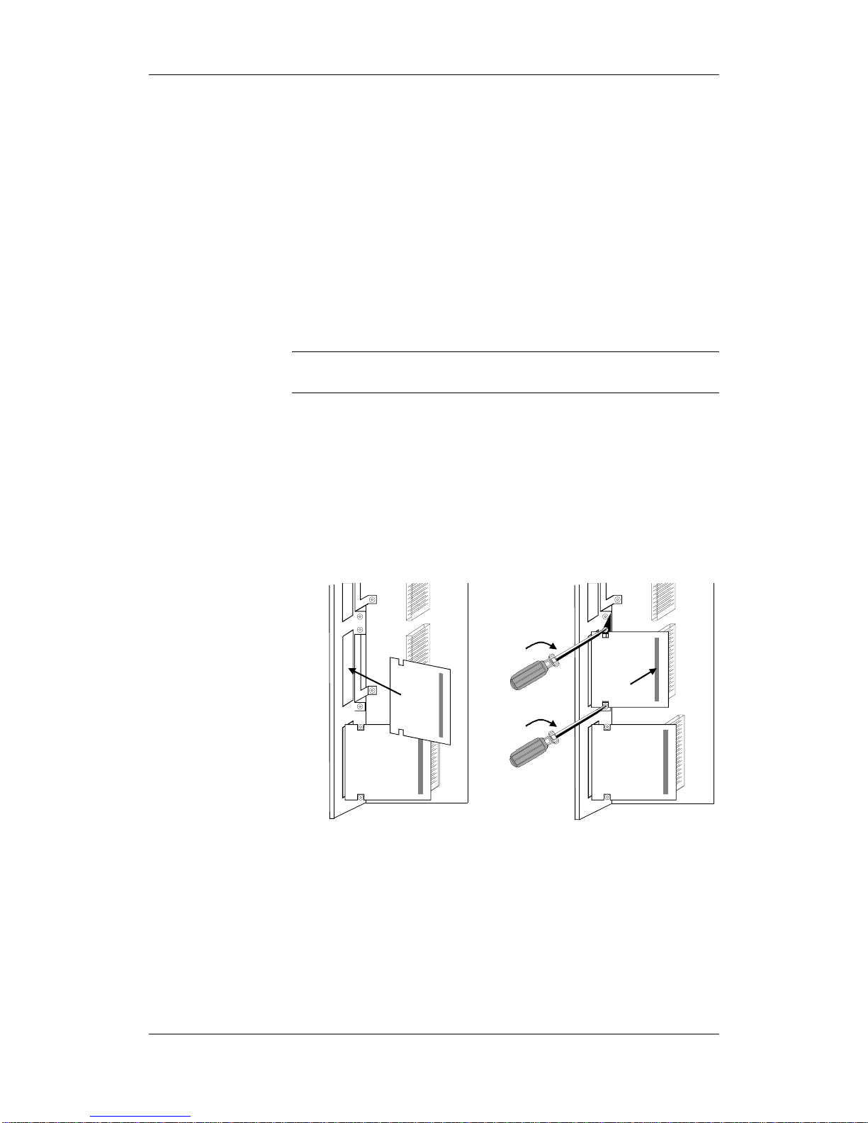
5.2.2 Installing optional boards on units with a width of 135 mm and
180 mm
Disconnecting the unit from the supply
Disconnect the unit from the power supply and power down the unit.
Remove the 24 V voltage supply for the electronics. Remove all
connecting cables.
♦ Loosen the 2 fixing screws on the front of the unit at the top. There
is no need to remove the screws completely, since cutouts are
provided in the housing to permit the front to come away after the
screws have been loosened.
♦ Carefully swing the upper front section forwards (approx. 30 °) away
from the housing.
♦ At the power section, open the locking lever of the ribbon cable that
connects up with the control electronics.
♦ Take off the front of the unit by moving it forwards.
Assembling and
mounting the unit
Designating the
optional board
DANGER
Opening the unit
Aotewell Ltd
www.aotewell.com
Industry Automation
HongKong|UK|China
sales@aotewell.com
+86-755-8660-6182
Page 20
Installation 05.2003
6SE7087-6JP60 Siemens AG
5-8 Operating Instructions SIMOVERT MASTERDRIVES
♦ Remove the cover of the selected slot on the front panel.
♦ To do so, you must carefully cut through the four connecting points
of the cover on the front panel with a thin knife.
♦ Undo the two optional board screws by about one turn each.
♦ Loosen the connection between the system connector and the
board so as to prevent any mechanical tension arising when the
screws are fully unscrewed.
♦ Take out the optional board screws and remove the board.
Optional boards can only be inserted in slot A and slot B. Slot C of the
unit is permanently pre-assigned for the terminal module EBV.
♦ Insert the optional board from the behind the broken-out slot conver
(
) until the position of the 64-pole system connector on the
electronic board corresponds with the position of the socket.
♦ Insert the option board into the 64-pole system connector on the
electronic board (
).
♦ Screw the optional board tight at the fastening points in the front
section of the optional board with the two screws (
).
Slot C Slot C
Slot B
Slot B
Slot A
Fig. 5-7 Installing the optional board
Removing the slot
cover
Removing the
optional board
Mounting the
optional board
NOTICE
Aotewell Ltd
www.aotewell.com
Industry Automation
HongKong|UK|China
sales@aotewell.com
+86-755-8660-6182
Page 21

05.2003 Installation
Siemens AG 6SE7087-6JP60
SIMOVERT MASTERDRIVES Operating Instructions 5-9
♦ Keep the front of the unit tilted about approximately 30 ° forwards
and insert the cutout of the lower guide plate - approaching from
below - into the strip on the power section.
♦ Insert the connection cable plug into the power section socket and
close the locking lever.
♦ Carefully return the front of the unit into the housing. Make sure that
the guide plates on the right-hand side of the front (viewed from the
front) enter the housing cutouts.
♦ Screw the front of the unit securely to the power section with the two
fixing screws.
♦ Re-connect all previously removed connecting cables.
♦ Check all connecting cables and the shield to make sure they sit
properly and are in the correct position.
♦ To designate the optional board, insert the relevant designation
plate into the envisaged position on the front of the unit.
♦ When the voltage has been switched in, the software of the unit
recognizes which optional bo ar ds have bee n ins tal le d and you can
then commence start-up.
Assembling and
mounting the unit
Connecting up the
unit
Designating the
optional board
Aotewell Ltd
www.aotewell.com
Industry Automation
HongKong|UK|China
sales@aotewell.com
+86-755-8660-6182
Page 22

05.2003 Installation in Conformance with EMC Regulations
Siemens AG 6SE7087-6JP60
SIMOVERT MASTERDRIVES Operating Instructions 6-1
6 Installation in Conformance with EMC
Regulations
The following contains a summary of general information and
guidelines which will make it easier for you to comply with EMC and CE
regulations.
♦ Ensure that there is a conductive connection bet ween the housing of
the converters or inverters and the mounting surface. The use of
mounting surfaces with good conducting properties (e.g. galvanized
steel plate) is recommended. If the mounting surface is insulated
(e.g. by paint), use contact washers or serrated washers.
♦ All of the metal cabinet parts must be connected through the largest
possible surface area and must provide good conductivity.
If necessary, use contact washers or serrated washers.
♦ Connect the cabinet doors to the cabinet frame using grounding
strips which must be kept as short as possible.
♦ For the connection between converter/inverter and motor, use
shielded cables which have to be grounded on both sides over a
large surface area.
If the motor terminal box is of plastic, additional grounding strands
have to be inserted.
♦ The shield of the motor supply cable must be connected to the
shield connection of the converter and to the motor mounting panel
through the largest possible surface area.
♦ The motor cable shield must not be interrupted by output reactors,
fuses or contactors.
♦ All signal cables must be shielded. Separate the signal cables
according to signal groups.
Do not route cables with digital signals unshielded next to cables
with analog signals. If you use a common signal cable for both, the
individual signals must be shielded from each other.
♦ Power cables must be routed separately away from signal cables (at
least 20 cm apart). Provide partitions between signal cables and
power cables. The partitions must be grounded.
♦ Connect the reserve cables/conductors to ground at both ends to
achieve an additional shie ldi ng ef f e ct .
♦ Lay the cables close to grounded plates as this will reduce the
injection of undesired signals.
♦ Eliminate any unnecessary cable lengths because these will
produce additional coupling capacitances and inductances.
♦ Use cables with braided shields. Cables with foil shields have a
shielding effect which is worse by a factor of five.
Aotewell Ltd
www.aotewell.com
Industry Automation
HongKong|UK|China
sales@aotewell.com
+86-755-8660-6182
Page 23

Installation in Conformance with EMC Regulations 05.2003
6SE7087-6JP60 Siemens AG
6-2 Operating Instructions SIMOVERT MASTERDRIVES
♦ Use a noise suppression filter in the incoming powerline.
Connect the noise suppression filter to ground and to the converter
through a large surface area.
It is best to directly mount the noise suppression filter on the same
good conductive mounting surface as the converter or inverter.
You must insert a line reactor between the noise suppression filter
and the unit.
♦ Contactor operating coils that are connected to the same supply
network as the converter or that are located in close proximity of the
converter must be connected to overvoltage limiters (e.g. RC
circuits, varistors).
Further information is contained in the chapter 3 "Instructions for
Design of Drives in Conformance with EMC Regulations" of the
Compendium. The Compendium can be found on the attached CD and
can also be ordered as a hard copy (Order No.: 6SE7087-6QX60).
This product has limited availability in accordance with IEC 61800-3.
This product can cause radio interference in residential areas. In such a
case, it may be necessary for the operator to take suitable action.
In line with the EMC product standard for variable-speed drives
EN 61800-3:1996 + A11:2000 Chapter 6.3.2.3 b) drive systems (PDS =
Power Drive Systems) have to compl y with the lim it values (in
accordance with Table 11 and Table 12 of the above-mentioned
standard).
For technical reasons there are a number of applications in which it is
not possible for PDS to comply with these limit values.
Such applications are:
♦ IT networks in complex systems
♦ Applications in which the necessary dynamic operational behavior is
limited on account of filter effects.
This note must be particularly observed for option L20 (operation on
non-grounded network s).
CAUTION
NOTE
Aotewell Ltd
www.aotewell.com
Industry Automation
HongKong|UK|China
sales@aotewell.com
+86-755-8660-6182
Page 24

05.2003 Connecting-up
Siemens AG 6SE7087-6JP60
SIMOVERT MASTERDRIVES Operating Instructions 7-1
7 Connecting-up
SIMOVERT MASTERDRIVES units are operated at high voltages.
The equipment must be in a no-voltage condition (disconnected from
the supply) before any work is carried out!
Only professionally trained, qualified personnel must work on or with
the units.
Death, severe bodily injury or significant property damage could occur if
these warning instructions are not observ ed.
Hazardous voltages are still present in the unit up to 5 minutes after it
has been powered down due to the DC link capacitors. Thus, the
appropriate delay time must be observed before working on the unit or
on the DC link terminals.
The power terminals and control terminals can still be live even when
the motor is stationary.
If the DC link voltage is supplied centrally, the converters must be
reliably isolated from the DC link voltage!
When working on an opened unit, it should be observed that live
components (at hazardous voltage levels) can be touched (shock
hazard).
The user is responsible that all the units are installed and connected-up
according to recognized regulations in that particular country as well as
other regionally valid regulations. Cable dimensioning, fusing,
grounding, shutdown, isolation and overcurrent protection should be
particularly observed.
Due to their physical characteristics, converters can produce DC
residual currents. If a residual-current protective device (residualcurrent-operated circuit-breaker) is used on the supply side of the
AC/AC converter - or of the rectifier unit in the case of multi-motor
drives - for protective purposes in case of indirect touching, only type B
to IEC 755 is permitted. Due to radio-interference suppression
capacitors and as a result of the parasitic capacity of the motor cable,
leakage currents flow which can lead to undesired responding of the
residual-current protective device.
In general, operation without faults is possible only under the following
conditions:
♦ Rated residual current of the residual-current protective
device ≥ 300 mA
♦ Short motor cables (l < 20 m)
♦ No radio-interference suppression filter built in
♦ Only one converter connected per residual-current protective device
DANGER
NOTICE
Aotewell Ltd
www.aotewell.com
Industry Automation
HongKong|UK|China
sales@aotewell.com
+86-755-8660-6182
Page 25
Connecting-up 05.2003
6SE7087-6JP60 Siemens AG
7-2 Operating Instructions SIMOVERT MASTERDRIVES
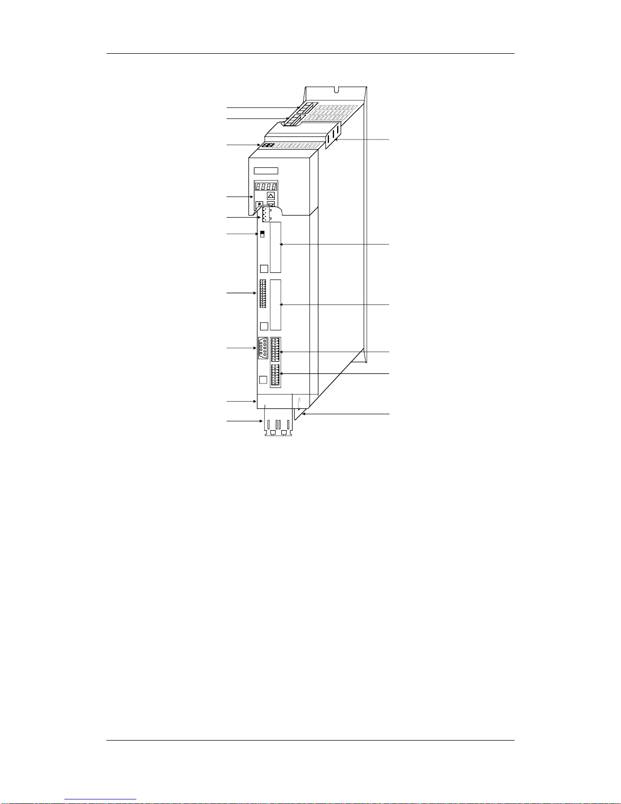
SIEMENS
X100
A
S1
BX101
CX103
PMU
RS232 / RS485 (U SS) X103
Slot A
Slot B
Terminal strip
X102
Motor connecti on X2
PE3
−−−−
++++
Encoder connection
X104
Mains connection X1
Brake r esisto r, X6
Capaci t or module
X3 DC link bus
module
DC24 V output,
RS485 (USS) X100
Bus terminating resistor (USS) S1
Termina l st r ip X1 01
Shield co nn ec t i on
for cont rol cables
Shield co nn ec t i on
for motor cable
External DC24 V supply X9
X533 Safe STOP (option)
Fig. 7-1 Connection overview for units up to 90 mm wide
Aotewell Ltd
www.aotewell.com
Industry Automation
HongKong|UK|China
sales@aotewell.com
+86-755-8660-6182
Page 26
05.2003 Connecting-up
Siemens AG 6SE7087-6JP60
SIMOVERT MASTERDRIVES Operating Instructions 7-3
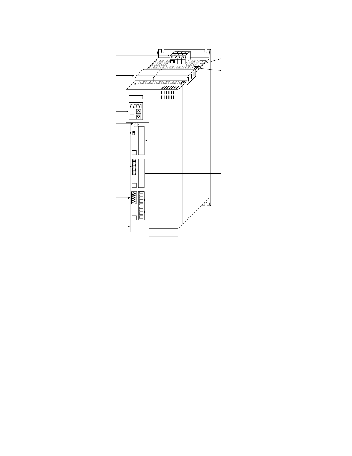
SIEMENS
A
S1
BX101
CX103
P
V1U1PE W1
PMU
RS232/ RS485 (U SS) X103
PE3
−−−−
++++
Slot A
Slot B
X533 Safe stop (option)
Terminal strip
X102
Encoder connection
X104
Mains connection X1
DC link bus module X3
DC24 V output,
RS485 (USS) X100
Bus termin at in g
resistor (USS) S1
X6 Brake resist or,
Capacitor module
X9 External DC24 V supply
Termina l st r ip X1 01
Motor connection X2
Fig. 7-2 Connection overview for units 135 mm wide
Aotewell Ltd
www.aotewell.com
Industry Automation
HongKong|UK|China
sales@aotewell.com
+86-755-8660-6182
Page 27
Connecting-up 05.2003
6SE7087-6JP60 Siemens AG
7-4 Operating Instructions SIMOVERT MASTERDRIVES
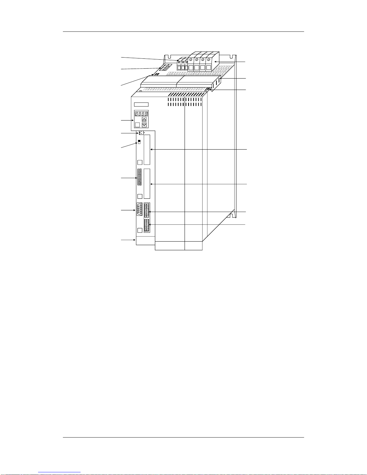
GHPE
SIEMENS
A
S1
BX101
CX103
P
W1V1U1PE
PMU
RS232/ RS485 (U SS) X103
PE3
−−−−
++++
Slot A
Slot B
X533 Safe stop
(option)
Terminal strip
X102
Encoder connection
X104
Brake r esisto r X6
Precharging
Capacitor module X7
External DC24 V
supply X9
X1 Mains connection
X3 DC link bus
module
DC24 V output,
RS485 (USS) X100
Bus termin at in g
resistor (USS) S1
Termina l st r ip X1 01
Motor connection X2
Fig. 7-3 Connection overview for units 180 mm wide
Aotewell Ltd
www.aotewell.com
Industry Automation
HongKong|UK|China
sales@aotewell.com
+86-755-8660-6182
Page 28

05.2003 Connecting-up
Siemens AG 6SE7087-6JP60
SIMOVERT MASTERDRIVES Operating Instructions 7-5
7.1 Power connections
Protective conductor
The protective conductor must be connected up both on the mains side
and on the motor side.
On account of leakage current through the interference-suppression
capacitors the following must be observed as per EN 50178
• A minimum cross-section of 10 mm
2
Cu must be used or
• If supply connections with cross-sections less than 10 mm
2
are
used, two protective conductors have to be connected up. The
cross-section of each of the protective conductors corresponds to
the cross-section of an outer conductor.
If the unit is mounted on a grounded mounting surface via a conductive
connection, the protective conductor cross section can be the same as
that of the phase conductor. The function of the second protective
conductor is afforded by the grounded mounting surface.
7.1.1 Power connections for units with a width up to 90 mm
There is an additional ground connection in the form of an M4 threaded
bolt at the upper section of the unit located next to the X1 mains
connection
.
This is used for connecting up the second protective conductor in
accordance with EN 50178.
The mains connection is situated at the top of the unit.
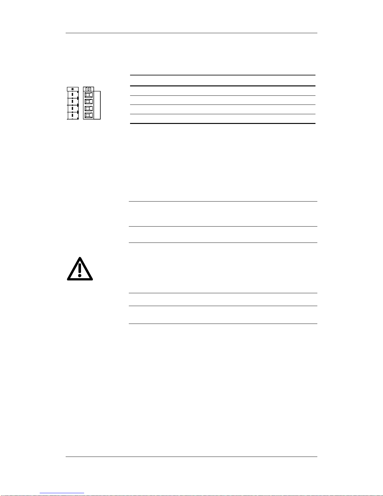
Terminal Meaning Range
PE1 Protective conductor connection
W1 Phase W1 / L3 3 AC 380 V - 480 V
V1 Phase V1 / L2 3 AC 380 V - 480 V
U1 Phase U1 / L1 3 AC 380 V - 480 V
Connectable cross-section: 4 mm² (AWG 10)
Terminal U1 is at the front when installed.
Table 7-1 Mains connection
The connector has to be screwed firmly to the housing (providing
resistance to vibration and protecting against being inadvertently
withdrawn).
WARNING
NOTE
Ground connection
X1 - Mains
connection
W1PE1 V1 U1
CAUTION
Aotewell Ltd
www.aotewell.com
Industry Automation
HongKong|UK|China
sales@aotewell.com
+86-755-8660-6182
Page 29

Connecting-up 05.2003
6SE7087-6JP60 Siemens AG
7-6 Operating Instructions SIMOVERT MASTERDRIVES
The DC link bus module serves as the electrical connection of the
individual units on the DC link side. It is of significance if further
inverters also have to be fed.
Bar Designation Meaning Range
3 PE3 Protective conductor connection
2 D / L- DC link voltage - DC 510 - 650 V
1 C / L+ DC link voltage + DC 510 - 650 V
Connectable cross-section: "Electro-plated copper" 3x10 mm, rounded
off according to DIN 46433 (EN 13601)
Bar 1 is at the front when installed.
Table 7-2 DC link bus module
The motor connection is located at the lower section of the unit.
Terminal Meaning Range
PE2 Protective conductor connection
U2 Phase U2 / T1 3 AC 0 V - 480 V
V2 Phase V2 / T2 3 AC 0 V - 480 V
W2 Phase W2 / T3 3 AC 0 V - 480 V
Connectable cross-section: 4 mm² (AWG 10)
Terminal PE2 is at the front when installed.
Table 7-3 Motor connection
The connector has to be screwed firmly to the housing (providing
resistance to vibration and protecting against being inadvertently
withdrawn).
The motor cables must be dimensioned in accordance with VDE 298,
Part 2.
After installation of the connector, the shield of the motor cable must be
fixed to the shield plate through a large surface area.
X3 - DC link bus
module
X2 – Moto
r
connection
U2PE2 V2 W 2
CAUTION
Aotewell Ltd
www.aotewell.com
Industry Automation
HongKong|UK|China
sales@aotewell.com
+86-755-8660-6182
Page 30
05.2003 Connecting-up
Siemens AG 6SE7087-6JP60
SIMOVERT MASTERDRIVES Operating Instructions 7-7
The connection for the external braking resistor and the pre-charging of
the capacitor module is provided on the top of the unit.
Terminal Meaning
C´ Pre-charging for capacitor module
G Braking resistor
H Braking resistor
D´ Pre-charging for capacitor module
Connectable cross-section: 4 mm² (AWG 10)
Terminal D’ is at the front when installed.
Table 7-4 Connection of the braking resistor and pre-charging of the capacit or
module
The motor cables must be dimensioned in accordance with VDE 298,
Part 2.
After installation of the connector, the shield of the motor cable must be
fixed to the shield plate through a large surface area.
The connector has to be screwed firmly to the housing (providing
resistance to vibration and protecting against being inadvertently
withdrawn).
♦ During operation, the full DC link voltage is always present at the
terminals for pre-charging the capacitor module.
♦ During pre-charging, the charging current of all connected capacitor
modules flows via the terminals.
♦ For reasons of protection, cables with 4 mm² Cu should be used at
connection X6!
Length of connecting cable between converter and external brake
resistor < 15 m.
X6 – Braking
resistor and precharging of the
capacitor module
GHD'C'
CAUTION
DANGER
CAUTION
Aotewell Ltd
www.aotewell.com
Industry Automation
HongKong|UK|China
sales@aotewell.com
+86-755-8660-6182
Page 31

Connecting-up 05.2003
6SE7087-6JP60 Siemens AG
7-8 Operating Instructions SIMOVERT MASTERDRIVES
7.1.2 Power connections for units with a width of 135 mm
The mains connection is to a terminal block on top of the unit.
Terminal Meaning Range
PE Protective conductor connection
U1 / L1 Phase U1 / L1 3AC 380 - 480 V
V1 / L2 Phase V1 / L2 3AC 380 - 480 V
W1 / L3 Phase W1 / L3 3AC 380 - 480 V
Connectable cross-section: 10 mm² (AWG 8), stranded
Viewed from the front, Terminal W1 is at the right.
Table 7-5 Mains connection
The DC link bus module serves as the electrical connection of the
individual units on the DC link side. It is of significance if further
inverters also have to be fed.
Bar Designation Meaning Range
3 PE3 Protective conductor connection
2 D / L- DC link voltage - DC 510 - 650 V
1 C / L+ DC link voltage + DC 510 - 650 V
Connectable cross-section: "Electro-plated copper" 3x10 mm, rounded
off according to DIN 46433 (EN 13601)
Bar 1 is at the front when installed.
Table 7-6 DC link bus module
The motor connection is to a terminal block at the bottom of the unit.
Terminal Meaning Range
PE Protective conductor connection
U2 / T1 Phase U2 / T1 3AC 0 V - 480 V
V2 / T2 Phase V2 / T2 3AC 0 V - 480 V
W2 / T3 Phase W2 / T3 3AC 0 V - 480 V
Connectable cross-section: 10 mm² (AWG 8), stranded
Viewed from the front, Terminal W2 is at the right.
Table 7-7 Motor connection
The motor cables must be dimensioned in accordance with VDE 298,
Part 2.
After installation of the connector, the shield of the motor cable must be
fixed to the shield plate through a large surface area.
X1 Mains connection
PE U1 V1 W1
X3 - DC link bus
module
X2 -
Moto
r
connection
PE U2 V2 W2
Aotewell Ltd
www.aotewell.com
Industry Automation
HongKong|UK|China
sales@aotewell.com
+86-755-8660-6182
Page 32

05.2003 Connecting-up
Siemens AG 6SE7087-6JP60
SIMOVERT MASTERDRIVES Operating Instructions 7-9
The connection for the external braking resistor and the pre-charging of
the capacitor module is provided on the top of the unit.
Terminal Meaning
D´ Pre-charging for capacitor module
H Braking resistor
G Braking resistor
C´ Pre-charging for capacitor module
Connectable cross-section: 4 mm² (AWG 10)
Terminal C’ is at the front when installed.
Table 7-8 Connection of the braking resistor and pre-charging of the capacit or
module
The connector has to be screwed firmly to the housing (providing
resistance to vibration and protecting against being inadvertently
withdrawn).
♦ During operation, the full DC link voltage is always present at the
terminals for pre-charging the capacitor module.
♦ During pre-charging, the charging current of all connected capacitor
modules flows via the terminals.
♦ For reasons of protection, cables with 4 mm² Cu should be used at
connection X6!
Length of connecting cable between converter and external brake
resistor < 15 m.
X6 - Braking resisto
r
and pre-charging of
the capacitor module
GHD'C'
CAUTION
DANGER
CAUTION
Aotewell Ltd
www.aotewell.com
Industry Automation
HongKong|UK|China
sales@aotewell.com
+86-755-8660-6182
Page 33

Connecting-up 05.2003
6SE7087-6JP60 Siemens AG
7-10 Operating Instructions SIMOVERT MASTERDRIVES
7.1.3 Power connections for units with a width of 180 mm
The mains connection is to a terminal block on top of the unit.
Terminal Meaning Range
PE Protective conductor connection
U1 / L1 Phase U1 / L1 3AC 380 - 480 V
V1 / L2 Phase V1 / L2 3AC 380 - 480 V
W1 / L3 Phase W1 / L3 3AC 380 - 480 V
Connectable cross-section: 25 mm² (AWG 4), stranded
Viewed from the front, Terminal W1 is at the right.
Table 7-9 Mains connection
The DC link bus module serves as the electrical connection of the
individual units on the DC link side. It is of significance if further
inverters also have to be fed.
Bar Designation Meaning Range
3 PE3 Protective conductor connection
2 D / L- DC link voltage - DC 510 - 650 V
1 C / L+ DC link voltage + DC 510 - 650 V
Connectable cross-section: "Electro-plated copper" 3x10 mm, rounded
off according to DIN 46433 (EN 13601)
Bar 1 is at the front when installed.
Table 7-10 DC link bus module
The motor connection is to a terminal block at the bottom of the unit.
Terminal Meaning Range
PE Protective conductor connection
U2 / T1 Phase U2 / T1 3AC 0 V - 480 V
V2 / T2 Phase V2 / T2 3AC 0 V - 480 V
W2 / T3 Phase W2 / T3 3AC 0 V - 480 V
Connectable cross-section: 16 mm² (AWG 6), stranded
Viewed from the front, Terminal PE is at the left.
Table 7-11 Motor connection
The motor cables must be dimensioned in accordance with VDE 298,
Part 2.
After installation of the connector, the shield of the motor cable must be
fixed to the shield plate through a large surface area.
X1 Mains connection
PE U1 V1 W1
X3 - DC link bus
module
X2 Motor connection
PE U2 V2 W2
Aotewell Ltd
www.aotewell.com
Industry Automation
HongKong|UK|China
sales@aotewell.com
+86-755-8660-6182
Page 34

05.2003 Connecting-up
Siemens AG 6SE7087-6JP60
SIMOVERT MASTERDRIVES Operating Instructions 7-11
The connection of the external braking resistor is to a terminal block on
the top of the unit on the left next to the mains connection.
Terminal Meaning
PE Protective conductor connection
H Braking resistor connection
G Braking resistor connection
Connectable cross-section: 10 mm² (AWG 4), stranded
Viewed from the front, Terminal PE is at the left.
Table 7-12 Braking resistor connection
Length of connecting cable between converter and brake resistor
< 15 m.
The connection for pre-charging the capacitor module is on the top of
the unit.
Terminal Meaning
C´ Pre-charging of capacitor module
C´ Pre-charging of capacitor module
D´ Pre-charging of capacitor module
D´ Pre-charging of capacitor module
Connectable cross-section: 4 mm² (AWG 10)
Terminal D’ is at the front when installed.
Table 7-13 Connection of precharging capacitor module
The connector has to be screwed firmly to the housing (providing
resistance to vibration and protecting against being inadvertently
withdrawn).
♦ During operation, the full DC link voltage is always present at the
terminals for pre-charging the capacitor module.
♦ During pre-charging, the charging current of all connected capacitor
modules flows via the terminals.
♦ For reasons of protection, cables with 4 mm
2
Cu should be used at
connection X7!
X6 – Braking
resistor connection
PE H G
CAUTION
X7 – Pre-charging o
f
capacitor module
D'C' C' D'
CAUTION
DANGER
Aotewell Ltd
www.aotewell.com
Industry Automation
HongKong|UK|China
sales@aotewell.com
+86-755-8660-6182
Page 35

Connecting-up 05.2003
6SE7087-6JP60 Siemens AG
7-12 Operating Instructions SIMOVERT MASTERDRIVES
7.2 Control connections
In the basic version, the unit has the following control connections:
♦ External 24 V supply
♦ 24 V voltage output, USS bus connection (RS485)
♦ Serial interface for PC or OP1S
♦ Control terminal strip.
Before the control cables and encoder cables are connected or
disconnected, the unit must be disconnected from the supply (24 V
electronic power supply and DC link/line voltag e)!
If this measure is not observed, this can result in defects on the
encoder. A defective encoder can cause uncontrolled axis movements.
The external 24 V infeed and all circuits connected to the control
terminals must meet the requirements for safety separation as
stipulated in EN 50178 (PELV circuit = Protective E
xtra Low Voltage).
Standard
connections
WARNING
WARNING
Aotewell Ltd
www.aotewell.com
Industry Automation
HongKong|UK|China
sales@aotewell.com
+86-755-8660-6182
Page 36

05.2003 Connecting-up
Siemens AG 6SE7087-6JP60
SIMOVERT MASTERDRIVES Operating Instructions 7-13
Bidirectional
digital inputs
and outputs
I
out
≤ 20 mA
X101
5V
24V
In
Out
Out
In
Out/In
In
Out
In
Out
In
Out
In
Out
In
4 bidirectional digital inputs/outputs
Outputs
Reference voltage
P10 V / N10 V
I ≤ 5 mA
Aux. power
supply
60 mA
5V
24V
In
5V
24V
2
1
3
4
5
6
7
8
19
10
11
12
Micro-
controller
P5V
BOOT
RS232 TxD
Digital inputs
Ri = 3.4 k
Ω
1
23
456789
RS232 RxD
PMU X103
13
14
P10
N10
Slot B
Slot A
BOOT
n.c.
15
16
D
A
D
A
In
5V
24V
1
2
17
18
D
A
S3
45
-10...+10 V
D
A
-10...+10 V
M
M
X102
In
In
A
S
I
C
30
29
28
27
26
25
24
23
Track A
Track B
Tacho M
zero
Control
Tacho P24
Mottemp BS
Mottemp
X104
Pulse
encoder
I≤190 mA
Motor
temperature
sensor
KTY84 or
PTC thermistor
AI 1
AI 2
Analog input 2
(non-floating)
11 bit + sign
U: R
in
= 60 k
Ω
I: R
in
= 250 Ω=(close S3)
10 bit + sign
U: I ≤ 5 mA
AO 2
AO 1
Analog output 2
Analog output 1
RS485P.
9
Inputs
21
20
HS1
HS2
Digital input
Ri = 3.4 kΩ
Analog input 1
(non-floating)
11 bit + sign
R
in
= 60 kΩ
Serial interface 2
(RS485)
24 V output
Serial interface 1
(RS232)
Floating contact switch
30 V / 0.5 A
Out
10 bit + sign
U: I ≤ 5 mA
I: 0...+20 mA
0...+20 mA
3
S4
RS485N.
Exte r nal 24 V
supply
OFF
ON
Bus terminating resistor
P24 AUX
M24
RS485N
RS485P
UART
35
36
P24V
M24
34
33
X9
1
2
+
24 V
ext.
-
int. 24 V-SNT
NTC
X100
Controller
F1
*)
*)
Type of fuse -F1: Miniature circuit-breaker 6 A characteristic C
e. g. Siemens 5SX2 106-7 (see attached sheet)
Fig. 7-4 Overview of the standard connections
Aotewell Ltd
www.aotewell.com
Industry Automation
HongKong|UK|China
sales@aotewell.com
+86-755-8660-6182
Page 37

Connecting-up 05.2003
6SE7087-6JP60 Siemens AG
7-14 Operating Instructions SIMOVERT MASTERDRIVES
In order to also enable the unit to be parameterized and monitored with
the DC link discharged (e.g. line interruption), an external 24 V voltage
supply is necessary. The two-pole connection required for this is
situated at the top of the unit.
With the DC link charged, the voltage is supplied by an internal switchmode power supply.
Terminal Designation Meaning Range
2 +24 V External 24 V supply DC 18 V - 30 V
1 0 V Reference potential DC 18 V - 30 V
Connectable cross-section: 2.5 mm² (AWG 12)
Terminal 1 is at the front when installed.
Table 7-14 External 24 V supply
In standby mode, the unit has a current drain of 700 mA. This is
increased if optional cards are inserted.
The unit is provided with a 24 V voltage output to which a maximum of
two further converters can be connected.
One further inverter can be connected to the 24 V voltage output in the
case of a unit with a housing width of 45 mm.
The USS bus connection is linked with the control electronics and the
9-pole SUB D socket of the serial interface.
The bus terminating resistor can, if required, be powered up by means
of the switch S1 located next to the bus connection. In the upper
position, the bus termination is switched in.
Power-up is necessary if the unit is located at one end of the USS bus.
Terminal Designation Meaning Range
33 +24 V (out) 24 V voltage output DC 18 V – 30 V
34 0 V Reference potential 0 V
35 RS485P (USS) USS bus connection RS485
36 RS485N (USS) USS bus connection RS485
Connectable cross-section: 2.5 mm² (AWG 12)
Terminal 33 is at the top when installed.
Table 7-15 24 V voltage output, USS bus
The RS485 interface can be operated either via -X100 or -X103.
X9 - External
24 V supply
1
2
X9 for 135 mm and
180 mm wide units
1
2
X9
X9 for 45 mm,
67.5 mm und 90 mm
wide units
X100 24 V voltage output,
USS bus
33
34
35
36
NOTICE
Aotewell Ltd
www.aotewell.com
Industry Automation
HongKong|UK|China
sales@aotewell.com
+86-755-8660-6182
Page 38

05.2003 Connecting-up
Siemens AG 6SE7087-6JP60
SIMOVERT MASTERDRIVES Operating Instructions 7-15
The following connections are provided on the control terminal strip:
♦ 4 combined digital inputs and outputs
♦ 2 additional digital inputs
♦ 1 analog input
♦ 1 analog output
♦ 24 V auxiliary voltage supply (max. 60 mA, output only!) for the
inputs.
If the digital inputs are supplied by an external 24 V voltage supply, it
must be referred to ground terminal X101.2. Terminal X101.1 (P24
AUX) must not be connected to the external 24 V supply.
Terminal Designation Meaning Range
1 P24 AUX Aux. voltage supply DC 24 V / 60 mA
2 M24 AUX Reference potential 0 V
3 DIO1 Digital input/output 1 24 V, 10 mA / 20 mA
4 DIO2 Digital input/output 2 24 V, 10 mA / 20 mA
5 DIO3 Digital input/output 3 24 V, 10 mA / 20 mA
6 DIO4 Digital input/output 4 24 V, 10 mA / 20 mA
7 DI5 Digital input 5 24 V, 10 mA
8 DI6 Digital input 6 24 V, 10 mA
9AI++++ Analog input ++++ 11 bit + sign
differential input:
10 AI−−−− Analog input −−−− ± 10 V / Ri = 40 kΩ
11 AO Analog output 10 bit + sign
± 10 V / 5 mA
12 M AO Ground analog output
Connectable cross-section: 0.14 mm² to 1.5 mm² (AWG 16)
Terminal 1 is at the top when installed.
Table 7-16 Control terminal strip
In the case of digital inputs, levels below 3 V are interpreted as low and
levels above 13 V as high.
X101 - Control
terminal strip
WARNING
Aotewell Ltd
www.aotewell.com
Industry Automation
HongKong|UK|China
sales@aotewell.com
+86-755-8660-6182
Page 39

Connecting-up 05.2003
6SE7087-6JP60 Siemens AG
7-16 Operating Instructions SIMOVERT MASTERDRIVES
♦ 10 V auxiliary voltage (max. 5 mA) for supplying external
potentiometers
♦ Analog output, suitable for use as current or voltage output
♦ 1 analog input, suitable for use as current or voltage input
♦ 1 additional digital input
♦ 1 floating NO contact
Terminal Designation Meaning Range
13 P10 V + 10 V supply for ext.
potentiometers
+ 10 V ± 1.3 %
I
max
= 5 mA
14 N10 V −−−− 10 V supply for ext.
potentiometers
−
−−
− 10 V ± 1.3 %
I
max
= 5 mA
15 AO2 Analog output 2 10 bit + sign
Voltage:
16 M AO2 Ground for analog output 2 ± 10 V / I
ma
x
= 5 mA
Current:
0...20 mA R ≤ 500 Ω
17 AI2 Analog input 2 11 bit + sign
Voltage:
18 M AI2 Ground for analog input 2
± 10 V / Ri = 60 kΩ
Current:
Rin = 250 Ω
19 DI7 Digital input 7 24 V, 10 mA
20 HS1 NO contact DC 30 V / max. 0.5 A
21 HS2 (floating) Minimum load 7 mA
Connectable cross-section: 0.14 mm2 to 1.5 mm2 (AWG 16)
Table 7-17 Control terminal strip X102
X102 Control terminal
strip
Aotewell Ltd
www.aotewell.com
Industry Automation
HongKong|UK|China
sales@aotewell.com
+86-755-8660-6182
Page 40

05.2003 Connecting-up
Siemens AG 6SE7087-6JP60
SIMOVERT MASTERDRIVES Operating Instructions 7-17
It is possible to connect either an OP1S or a PC with RS232 or RS485
serial interface via the 9-pole SUB D socket. There are different
connecting cables for the PC for the various transmission protocols.
The 9-pole SUB D socket is internally coupled with the USS bus, thus
enabling data exchange with other nodes link ed via the USS bus .
This interface is also used for loading software.
Pin Designation Meaning Range
1 NC Not assigned Low active
2 RS232 RxD Receive data via RS232 RS232
3 RS485 P Data via RS485 interface RS485
4 Boot Control signal for software update Low active
5 M5 AUX Reference potential to P5V 0 V
6 P5V 5 V aux. voltage supply +5 V, max. 200 mA
7 RS232 TxD Transmit data via RS232 RS232
8 RS485 N Data via RS485 interface RS485
9 M_RS232/485 Digital ground (choked)
Table 7-18 Serial interface
The RS485 interface can be operated either via -X100 or -X103.
The control terminal strip includes a connection for a pulse generator
(HTL unipolar) and the motor temperature evaluation circuit with KTY or
PTC.
Terminal Designation Meaning Range
23 −−−− V
PP
Ground for power supply
24 Track A Connection track A
25 Track B Connection track B
26 Zero pulse not evaluated
27 CTRL Connection control track
HTL unipolar;
L ≤ 3 V, H ≥ 8 V
28 + V
PP
Pulse generator power
supply
24 V
I
max
= 190 mA
29 −−−− Temp Minus (−−−−) terminal
KTY84/PTC
30 + Temp Plus (++++) terminal
KTY84/PTC
KTY84: 0...200 °C
PTC: R
cold
≤ 1.5 kΩ
Connectable cross-section: 0.14 mm2 to 1.5 mm2 (AWG 16)
Table 7-19 Control terminal strip X104
X103 - Serial
interface
1
5
6
9
NOTICE
X104 –
Control terminal
strip
Aotewell Ltd
www.aotewell.com
Industry Automation
HongKong|UK|China
sales@aotewell.com
+86-755-8660-6182
Page 41

Connecting-up 05.2003
6SE7087-6JP60 Siemens AG
7-18 Operating Instructions SIMOVERT MASTERDRIVES
With the safe stop option, the power supply for the transmission of
pulses into the power section can be interrupted through a safety relay.
This ensures that the unit will definitely not generate a rotating field in
the connected motor.
Even if the control electronics generates trigger commands, the power
section cannot move the motor.
This enables mechanical work to be performed on the drive or on
coupled machine parts with energi zed li ne vo lta ge and with out el ectr ic al
isolation of the motor to the unit.
The "safe stop" function is a "device for the prevention of unexpected
starting" in accordance with EN 60204-1, Section 5.4, and meets the
requirements of Safety Category 3 to EN 954-1 by virtue of appropriate
external protective circuitry.
The safe stop option is not suitable for bringing a rotating motor to a
quick halt as by de-energizing the trigger signals, the motor is only
braked by the connected load.
The motor cannot produce a torque when the "safe stop" function is
activated. Where external forces are applied to the drive axes or with
drives that are not self-arresting (e.g. vertical axes), additional holding
devices, e.g. brakes, are required.
A residual risk cannot be precluded in the case of two simultaneous
errors in the power section. In this case, the drive can be aligned by a
small angle of rotation (asynchronous motors: Max. 1 slot pitch in the
remanence range, corresponding to about 5° to 15°).
♦ The safe stop option does not generate electrical is ol atio n bet ween
the motor terminals and the power section.
♦ In the "safe stop" state, hazardous voltages are still present at the
motor terminals!
The products described here have been developed to perform safetyrelated functions as part of a complete system or machine. A complete,
safety-related system generally includes sensors, evaluation units,
signaling devices and strategies for safe shutdown. The manufacturer
of an installation or machine is responsible for providing an appropriate
overall safety system. Siemens AG, its regional offices and associated
companies (referred to as "Siemens" below) cannot guarantee all the
characteristics of a complete installation or machine that has not been
designed by Siemens.
Siemens shall not be liable for recommendations that are made or
implied as a result of the following description. No new warranty or
liability claims over and above those stated in the Siemens general
delivery conditions can be inferred from the following description.
X533 - Safe stop
option
WARNING
WARNINGS
NOTE
Aotewell Ltd
www.aotewell.com
Industry Automation
HongKong|UK|China
sales@aotewell.com
+86-755-8660-6182
Page 42

05.2003 Connecting-up
Siemens AG 6SE7087-6JP60
SIMOVERT MASTERDRIVES Operating Instructions 7-19
The safe stop option comprises the safety relay and the connecting
terminals for relay triggering and a checkback contact.
Terminal Designation Meaning Range
1 Contact 1 Checkback "safe stop" DC 20 V – 30 V
2 Contact 2 Checkback "safe stop" 1 A
3 Control input
"safe stop"
Rated resistance of field coil
≥ 823 Ω ± 10 % at 20 °C
DC 20 V – 30 V
max. operating
frequency: 6/min
4 P24 DC Supply voltage "safe stop"
DC 24 V /
30 mA
Connectable cross-section: 1.5 mm² (AWG 16)
Terminal 4 is at the front when installed.
Table 7-20 Terminal assignment for the "safe stop" option
The field coil of the safety relay is connected at one end to the
grounded electronics frame. When the field coil is supplied via an
external 24 V supply, its negative pole must be connected to ground
potential. The external 24 V supply must comply with the requirements
for PELV circuits to EN 50178 (DIN VDE 0160).
In the shipped state, a jumper is inserted between terminals 3 and 4.
The jumper must be removed before the "SAFE STOP" function can be
used and an external control for selecting the function connected.
If the safety relay is supplied via the internal supply at X533:4, the
external 24 V supply must deliver at least 22 V at terminal X9:1/2 to
ensure that the relay picks up reliably (internal voltage drop).
1 42 3
Optocoupler /
fibre optics
supply
P15
Terminal strip
- X533
X533 - Safe stop
option
Aotewell Ltd
www.aotewell.com
Industry Automation
HongKong|UK|China
sales@aotewell.com
+86-755-8660-6182
Page 43

Connecting-up 05.2003
6SE7087-6JP60 Siemens AG
7-20 Operating Instructions SIMOVERT MASTERDRIVES
The checkback contacts of the safety relay are capable of at least
100,000 switching cycles at the specified load (30 V DC / 1 A). The
mechanical service life is about 10
6
switching cycles. The safety relay is
an important component in ensuring reliability and availability of the
machine. For this reason, the pcb with the safety relay must be
replaced in the case of malfunction. In this case, the unit must be
returned for repair or replaced. Function checks must be carried out at
regular intervals, which must be defined in compliance with Employer's
Liability Insurance Regulation BGV A1 §39, para. 3. Accordingly,
function checks must be performed as required by the relevant service
conditions, but at least once a year and addit ion al l y after initi al
commissioning and any modification and/or maintenance work.
P24
1
2
3
4
M
-Cu control
board
PV
SIMOVERT
MASTERDRIVES
Option K80
X101
X533
U1 V1 W1
U2 V2 W2
X
Y
M
3
-K1
K1
-Q1Main switch
Mains
closed
open
A1 Y10
Y21 Y22Y11 Y12
13
14
3TK2828
24
23
31 47 57
32 48 58
Y33 Y34 PE A2
A1 Y10 Y11 Y12 Y21 Y22 13
14
3TK2828
24
23
31 47 57
32 48 58
Y33 Y34 PE A2
OFF3
n = 0
-K2
-Y1
K2
-S1
K1
K2
P24
M
X: Binary input, connect to OFF3
e. g. X101.8 --> P558 = 21
Y: Binary output, connect to "Comparison value
reached"
e. g. X101.6 --> P654 = 120; P796 = 0 (comparison value)
Emerg.
stop
S2
Request protective
device enable
S3
Reset
OFF1
Fig. 7-5 Sample application of "safe stop" function with contactor safety
combination for monitoring a moving protective device in Safety Category
3 to EN 954-1
Aotewell Ltd
www.aotewell.com
Industry Automation
HongKong|UK|China
sales@aotewell.com
+86-755-8660-6182
Page 44

05.2003 Connecting-up
Siemens AG 6SE7087-6JP60
SIMOVERT MASTERDRIVES Operating Instructions 7-21
All external cables relevant to the safety function are protected, e.g.
installed in cable ducts, to preclude the possibility of short circuits.
Cables must be installed in compliance with the requirements of
EN 60204-1, Section 14.
In the circuit shown in Fig. 7-5, the tumbler does not release the moving
protective device until the drive has stopped. It may be possible to omit
the tumbler if the risk assessment of the machine deems this to be
safe. In this case, the NC contact of the protective device is connected
directly to terminals Y11 and Y12 and elec tr omagnet Y1 is omitted.
Binary input X is negated with signal "OFF3", i.e. at 24 V, the converter
decelerates the motor to zero speed along the parameterized
deceleration ramp. The converter signals zero speed via binary output
Y, thus energizing relay K2.
Once the motor has stopped, the safety relay in the converter is opened
and the coil of main contactor K1 remains at 24 V via the checkback
contact. If contacts in the safety relay are sticking, the checkback
contacts do not close and the safety combination on the right
deenergizes main contactor K1 via delayed contacts 47/48 when the
set delay period expires.
Aotewell Ltd
www.aotewell.com
Industry Automation
HongKong|UK|China
sales@aotewell.com
+86-755-8660-6182
Page 45

Connecting-up 05.2003
6SE7087-6JP60 Siemens AG
7-22 Operating Instructions SIMOVERT MASTERDRIVES
7.3 Conductor cross-sections, fuses, reactors
If the unit is mounted conductively on a grounded mounting surface, the
cross section of the protective conductor can be the same as that of the
phase conductor.
In the case of insulated installation on units up to 90 mm wide, a
second protective conductor (with the same cross section as the line
conductor) must be connected to ground (M4 threaded bolts on the top
of the unit next to the mains terminal).
In the case of a width larger than 90 mm the cross-section of the
protective conductor must be at least 10 mm
2
.
Order No.
Mains connection
Main
con-
tactor
Motor
connection
Braking
resistor,
capacitor
module
connection
Cross-section Recommended fuses Line Cross-section Cross-section
6SE70... VDE AWG gR (SITOR) gL NH reactor VDE AWG VDE AWG
[mm²] [A] 3NE [A] 3NA 4EP 3RT [mm²] [mm²]
11-5EP60 1.5 16 16 1813-0 10 3803 3200-4US 1015 1.5 16 1.5 16
13-0EP60 1.5 16 16 1813-0 10 3803 3200-5US 1015 1.5 16 1.5 16
15-0EP60 1.5 16 16 1813-0 10 3803 3200-2US 1015 1.5 16 2.5 14
18-0EP60 1.5 16 16 1813-0 16 3805 3400-2US 1015 1.5 16 2.5 14
21-0EP60 2.5 14 16 1813-0 16 3805 3400-1US 1015 1.5 16 2.5 14
21-4EP60 4 10 20 1814-0 25 3810 3500-0US 1016 2.5 14 4 10
22-1EP60 10 6 25 1815-0 25 3810 3600-4US 1016 4 10 4 10
22-7EP60 10 6 35 1803-0 35 3814 3600-5US 1025 10 6 4 10
23-4EP60 16 4 40 1802-0 40 3817 3700-2US 1034 10 6 4 10
Table 7-21 Recommended conductor cross-sections, fuses, reactors
The dimensioning of the supply connection (conductor crosssection and fuse) is stated in Table 7-21 for use as a single drive.
Both the cables and the semiconductors are protected by fuses with gR
characteristics.
Protective
conductor
WARNING
WARNING
NOTE
Aotewell Ltd
www.aotewell.com
Industry Automation
HongKong|UK|China
sales@aotewell.com
+86-755-8660-6182
Page 46

05.2003 Connecting-up
Siemens AG 6SE7087-6JP60
SIMOVERT MASTERDRIVES Operating Instructions 7-23
gL fuses only provide reliable protection for the cables, but not the
semiconductors.
It is not imperative to operate the units via a main contactor.
If the units are connected to the supply system without a main contactor
which can interrupt the incoming supply in the event of a fault, the unit
may suffer further damage.
7.4 Combinations of units
For simple configuration of multi-axis drives, one or several Compact
PLUS DC/AC inverters can be fed from the DC link of the Compact
PLUS AC/AC converters.
The total drive power of the inverters must not exceed the drive power
of the converter. A simultaneity factor of 0.8 applies here.
For example, a 4 kW inverter and a 1.5 kW inverter can be connected
to a converter with a drive power of 5.5 kW by a common DC bus.
The line-side components are rated according to the total power of all
converters and inverters. In the case of a multi-axis drive from one
5.5 kW converter, one 4 kW inverter and one 1.5 kW inverter, the lineside components must be rated for an 11 kW converter. If the total
power does not exactly equal that of one converter, then the line-side
components must be dimensioned according to the next-higher
converter power.
If more than two inverters are connected to the DC bus of a converter,
an external DC 24 V supply must be provided for these inverters. Only
one further inverter can be connected to the 24 V voltage output in the
case of a converter with a housing width of 45 mm.
To support the DC link circuit, a capacitor module can be connected to
a Compact PLUS AC/AC converter.
WARNING
WARNING
WARNING
NOTICE
Aotewell Ltd
www.aotewell.com
Industry Automation
HongKong|UK|China
sales@aotewell.com
+86-755-8660-6182
Page 47

05.2003 Parameterization
Siemens AG 6SE7087-6JP60
SIMOVERT MASTERDRIVES Operating Instructions 8-1
8 Parameterization
It is possible to parameterize the units of the SIMOVERT
MASTERDRIVES series by various methods of parameter input. Every
unit can be set via the dedicated parameterizing unit (PMU) without the
need to use additional components.
Each unit is supplied with the user software DriveMonitor and
comprehensive electronic documentation on a CD. In the case of
installation on a standard PC the units can be parameterized via the
serial interface of the PC. The software provides extensive parameter
aids and a prompted start-up function.
The unit can be further parameterized by entering parameters with the
OP1S manual operator panel and via a controller at the field bus level
(e.g. Profibus).
8.1 Parameter menus
Parameters with related functions are compiled in menus for structuring
the parameter set stored in the units. A menu thus represents a
selection out of the entire supply of parameters of the unit.
It is possible for one parameter to belong to several menus. The
parameter list indicates which individual menus a parameter belongs to.
Assignment is effected via the menu number allocated to each menu.
Aotewell Ltd
www.aotewell.com
Industry Automation
HongKong|UK|China
sales@aotewell.com
+86-755-8660-6182
Page 48

Parameterization 05.2003
6SE7087-6JP60 Siemens AG
8-2 Operating Instructions SIMOVERT MASTERDRIVES
General parameters
Terminals
Communication
Control and status words
Setpoint channel
Motor/encoder
Control/gating unit
Sequence control
Diagnostics
Functions
Releases
Free blocks
Technology
SCom1/SCom2
Field bus inter faces
SIMOLINK
SCB/SCI
Motor data
Encoder data
Posit io n co ntr o l
Speed control
Current con trol
V/f ope n-loop contro l
Gating unit
Faults/alarms
Messages/displays
Trace
Synchronism
Positioning
Setting up/MDI
User parameters
Parameter menu
Fixed setti ngs
Quick
parameterization
Board
configuration
Drive setting
Download
Upread/free access
Power section
definition
Menu level 1
Select vi a
P60 Menu Select
Menu level 2
(only on OP1S)
Menu level 3
(only on OP1S)
P358 Key P359 Lock
P60
By enter ing a password in P 359,
access to the menus in the gray
shaded area can b e pr ohibi ted to
unauthorized persons
1)
1)
1)
1)
1)
only MASTERDRIVES Motion Control
Basi c positio ner 1)
Fig. 8-1 Parameter menus
Aotewell Ltd
www.aotewell.com
Industry Automation
HongKong|UK|China
sales@aotewell.com
+86-755-8660-6182
Page 49

05.2003 Parameterization
Siemens AG 6SE7087-6JP60
SIMOVERT MASTERDRIVES Operating Instructions 8-3
The parameter menus have several menu levels. The first level
contains the main menus. These are effective for all sources of
parameter inputs (PMU, OP1S, DriveMonitor, field bus interfaces).
The main menus are selected in parameter P60 Menu Selection.
Examples:
P060 = 0 "User parameters" menu selected
P060 = 1 "Parameter menu" selected
...
P060 = 8 "Power section definition" menu selected
Menu levels 2 and 3 enable the parameter set to be more extensively
structured. They are used for parameterizing the units with the OP1S
operator control panel.
P060 Menu Description
0 User parameters • Freely configurable menu
1 Parameter menu • Contains complete parameter set
• More extensive structure of the functions achieved by using
an OP1S operator control panel
2 Fixed settings • Used to perform a parameter reset to a factory or user setting
3Quick
parameterization
• Used for quick parameterization with parameter modules
• When selected, the unit switches to status 5 "Drive setting"
4 Board configuration • Used for configuring the optional boards
• When selected, the unit switches to status 4 "Board
configuration"
5 Drive setting
• Used for detailed parameterization of important motor,
encoder and control data
• When selected, the unit switches to status 5 "Drive setting"
6 Download • Used to download parameters from an OP1S, a PC or an
automation unit
• When selected, the unit switches to status 21 "Download"
7 Upread/free access • Contains the complete parameter set and is used for free
access to all parameters without being restricted by further
menus
• Enables all parameters to be upread/upload by an OP1S, PC
or automation unit
8
Power section
definition
• Used to define the power section (only necessary for units of
the Compact and chassis type)
• When selected, the unit switches to status 0 "Power section
definition"
Table 8-1 Main menus
Menu levels
Main menus
Aotewell Ltd
www.aotewell.com
Industry Automation
HongKong|UK|China
sales@aotewell.com
+86-755-8660-6182
Page 50

Parameterization 05.2003
6SE7087-6JP60 Siemens AG
8-4 Operating Instructions SIMOVERT MASTERDRIVES
In principle, parameters are firmly assigned to the menus. However, the
"User parameters" menu has a special status. Parameters assigned to
this menu are not fixed, but can be changed. You are thus able to put
together the parameters required for your application in this menu and
structure them according to your needs. The user parameters can be
selected via P360 (Select UserParam).
In order to prevent undesired parameterization of the units and to
protect your know-how stored in the param eter i zation, it is possib le to
restrict access to the parameters by defining your own passwords with
the parameters:
♦ P358 key and
♦ P359 lock.
User parameters
Lock and key
Aotewell Ltd
www.aotewell.com
Industry Automation
HongKong|UK|China
sales@aotewell.com
+86-755-8660-6182
Page 51

05.2003 Parameterization
Siemens AG 6SE7087-6JP60
SIMOVERT MASTERDRIVES Operating Instructions 8-5
8.2 Changeability of parameters
The parameters stored in the units can only be changed under certain
conditions. The following preconditions must be satisfied before
parameters can be changed:
Preconditions Remarks
• Either a function parameter or a BICO
parameter must be involved (identified
by upper-case letters in the parameter
number).
Visualization parameters
(identified by lower-case letters
in the parameter number)
cannot be changed.
• Parameter access must be granted for
the source from which the parameters
are to be changed.
Release is given in P053
Parameter access.
• A menu must be selected in which the
parameter to be changed is contained.
The menu assignment is
indicated in the parameter list
for every parameter.
• The unit must be in a status which
permits parameters to be changed.
The statuses in which it is
possible to change parameters
are specified in the parameter
list.
Table 8-2 Preconditions for being able to change parameters
The current status of the units can be interrogated in parameter r001.
Status (r001) P053 Result
"Ready for ON" (09) 2 P222 Src n(act) can only be changed via the PMU
"Ready for ON" (09) 6 P222 Src n(act) can be changed via the PMU and
SCom1 (e.g. OP1S)
"Operation" (14) 6 P222 Src n(act) cannot be changed on account of
the drive status
Table 8-3 Influence of drive status (r001) and parameter access (P 053) on the
changeability of a parameter
NOTE
Examples
Aotewell Ltd
www.aotewell.com
Industry Automation
HongKong|UK|China
sales@aotewell.com
+86-755-8660-6182
Page 52

Parameterization 05.2003
6SE7087-6JP60 Siemens AG
8-6 Operating Instructions SIMOVERT MASTERDRIVES
8.3 Parameter input with DriveMonitor
Operation of DriveMonitor via the PC and USS interfaces is described
below.
8.3.1 Installation and connection
8.3.1.1 Installation
A CD is included with the devices of the MASTERDRIVES Series when
they are delivered. The operating tool supplied on the CD
(DriveMonitor) is automatically installed from this CD. If "automatic
notification on change" is activated for the CD drive on the PC, user
guidance starts when you insert the CD and takes you through
installation of DriveMonitor. If this is not the case, start file
"Autoplay.exe" in the root directory of the CD.
8.3.1.2 Connection
There are two ways of connecting a PC to a device of the SIMOVERT
MASTERDRIVES Series via the USS interface. The devices of the
SIMOVERT MASTERDRIVES Series have both an RS232 and an
RS485 interface.
The serial interface that PCs are equipped with by default functions as
an RS232 interface. This interface is not suitable for bus operation and
is therefore only intended for operation of a SIMOVERT
MASTERDRIVES device.
6
7
8
9
5
4
3
2
1
6
7
8
9
5
4
3
2
1
To PC COMx
socket
Device side
-X300 (compact PLUS -X103)
9-pin SUB-D connector
X300:
1 Ground
2 RxD (RS232)
3 Rx+/Tx+ (RS485)
4
5 Ground
6 +5V (OP1S)
7 TxD (RS232)
8 Rx-/Tx- (RS485)
9 Ground
Fig. 8-2 Connecting cable for connecting PC COM(1-4) to SIMOVERT
MASTERDRIVES X300
The RS485 interface is multi-point capable and therefore suitable for
bus operation. You can use it to connect 31 SIMOVERT
MASTERDRIVES with a PC. On the PC, either an integrated RS485
interface or an RS232 ↔ RS485 interface converter is necessary. On
the device, an RS485 interface is integrated into the -X103 connection.
For the cable: see pin assignment -X300 and device documentation of
the interface converter.
RS232 interface
RS485 interface
Aotewell Ltd
www.aotewell.com
Industry Automation
HongKong|UK|China
sales@aotewell.com
+86-755-8660-6182
Page 53

05.2003 Parameterization
Siemens AG 6SE7087-6JP60
SIMOVERT MASTERDRIVES Operating Instructions 8-7
8.3.2 Drive configuration DriveMonitor
DriveMonitor starts with an empty drive window. Via the menu "Set up
an ONLINE connection..." the USS bus can be scanned for connected
devices:
Aotewell Ltd
www.aotewell.com
Industry Automation
HongKong|UK|China
sales@aotewell.com
+86-755-8660-6182
Page 54

Parameterization 05.2003
6SE7087-6JP60 Siemens AG
8-8 Operating Instructions SIMOVERT MASTERDRIVES
The USS bus is scanned with the current baud rate. The baud rate can
be changed via "Tools ONLINE Settings", see section 8.3.2.1.
Aotewell Ltd
www.aotewell.com
Industry Automation
HongKong|UK|China
sales@aotewell.com
+86-755-8660-6182
Page 55

05.2003 Parameterization
Siemens AG 6SE7087-6JP60
SIMOVERT MASTERDRIVES Operating Instructions 8-9
8.3.2.1 Setting the interface
You can configure the interface with menu Tools ONLINE Settings.
Fig. 8-3 Online settings
The following settings (Fig. 8-4) are possible:
♦ Tab card "Bus Type", options
USS (operation via serial interface)
Profibus DP (only if DriveMonitor is operated under Drive ES).
♦ Tab card "Interface"
You can enter the required COM interface of the PC (COM1 to
COM4) and the required baudrate here.
Set the baudrate to the baudrate parameter i zed in SIMO VERT
MASTERDRIVES (P701) (factory setting 9600 baud).
Further settings: operating mode of the bus in RS485 operation;
setting according to the description of the interface converter
RS232/RS485.
♦ Tab card "Extended"
Request retries and Response timeout; here you can increase the
values already set if communication errors occur frequently.
Fig. 8-4 Interface configuration
NOTE
Aotewell Ltd
www.aotewell.com
Industry Automation
HongKong|UK|China
sales@aotewell.com
+86-755-8660-6182
Page 56

Parameterization 05.2003
6SE7087-6JP60 Siemens AG
8-10 Operating Instructions SIMOVERT MASTERDRIVES
8.3.2.2 Drive settings
With menu File New ... you can create a new drive for
parameterization (see Fig. 8-5). The system creates a download file
(*.dnl), in which the drive characteristic data (type, software version) are
stored. You can create the download file on the basis of an empty
parameter set or the factory setting.
Fig. 8-5 Creating a new drive
Once you have created a drive, you can start it again with the menu
function File Open for parameterization by opening the download
file. The last four drives can be opened via "Parameter sets last dealt
with".
When you create a new drive, the window "Properties - Drive" (Fig. 8-6)
opens. Here you must enter the following data:
♦ In dropdown list box "Device type", select the type of device (e.g.
MASTERDRIVES VC(Plus)). You can only select the devices
stored.
♦ In dropdown list box "Software version", you can select the software
version of the device. You can generate databases for (new)
software versions that are not list ed when you start onl in e
parameterization.
♦ You must only specify the bus address of the drive during online
operation (switchover with button Online/Offline)
The specified bus address must be the same as that of the
parameterized SST bus address in SIMOVERT MASTERDRIVES
(P700).
NOTE
Aotewell Ltd
www.aotewell.com
Industry Automation
HongKong|UK|China
sales@aotewell.com
+86-755-8660-6182
Page 57

05.2003 Parameterization
Siemens AG 6SE7087-6JP60
SIMOVERT MASTERDRIVES Operating Instructions 8-11
Field "Number of PCD" has no special significance for the
parameterization of MASTERDRIVES and should be left at "2".
If the value is changed, it must be/remain ensured that the setting value
in the program matches the value in parameter P703 of the drive at all
times.
Fig. 8-6 Drive setting
NOTE
Aotewell Ltd
www.aotewell.com
Industry Automation
HongKong|UK|China
sales@aotewell.com
+86-755-8660-6182
Page 58

Parameterization 05.2003
6SE7087-6JP60 Siemens AG
8-12 Operating Instructions SIMOVERT MASTERDRIVES
Settings for Drive Navigator under Tools -> Options:
Fig. 8-7 Drive Navigator
Drive Navigato
r
Aotewell Ltd
www.aotewell.com
Industry Automation
HongKong|UK|China
sales@aotewell.com
+86-755-8660-6182
Page 59

05.2003 Parameterization
Siemens AG 6SE7087-6JP60
SIMOVERT MASTERDRIVES Operating Instructions 8-13
Toolbar of the Drive Navigator
= Assisted commissioning
= Direct to parameter list
= General diagnostics
= Download parameter file to drive
= Save drive parameters to a file
= Load standard application
= 1:1 device exchange
= Assisted F01 technology COMM
= Basic positioner operating screens
Aotewell Ltd
www.aotewell.com
Industry Automation
HongKong|UK|China
sales@aotewell.com
+86-755-8660-6182
Page 60

Parameterization 05.2003
6SE7087-6JP60 Siemens AG
8-14 Operating Instructions SIMOVERT MASTERDRIVES
After you have confirmed the drive settings with ok, you can still specify
the name and the storage location of the download file to be created.
After that, the parameter list opens in offline mode (Fig. 8-8).
With buttons Offline, Online (RAM), Online (EEPROM) (Fig. 8-8 [1]) you
can switch modes. When you switch to online mode, device
identification is performed. If the configured device and the real device
do not match (device type, software version), an alarm appears. If an
unknown software version is recognized, the option of creating the
database is offered. (This process takes several minutes.)
1
2
Fig. 8-8 Drive window/parameter list
The DriveMonitor drive window has a directory tree for navigation
purposes (Fig. 8-8 [2]). You can deselect this additional operating tool
in menu View.
The drive window contains all elements required for the
parameterization and operation of the connected device. In the lower
bar, the status of the connection with the device is displayed:
Connection and device ok
Connection ok, device in fault state
Connection ok, device in alarm state
Device is parameterized offline
No connection with the device can be established (only offline
parameterization possible).
Aotewell Ltd
www.aotewell.com
Industry Automation
HongKong|UK|China
sales@aotewell.com
+86-755-8660-6182
Page 61

05.2003 Parameterization
Siemens AG 6SE7087-6JP60
SIMOVERT MASTERDRIVES Operating Instructions 8-15
If no connection with the device can be established because the device
does not physically exist or is not connected, you can perform offline
parameterization. First switch to offline mode. In this mode, you can
edit the parameter data set on the basis of the factory setting. In that
way, you can create an individually adapted do wnl oad file, whic h you
can load into the device later.
8.3.3 Parameterization
8.3.3.1 Structure of the parameter lists, parameterization with DriveMonitor
Parameterization using the parameter list is basically the same as
parameterization using PMU (See Section 8.4). The parameter list
provides the following advantages:
♦ Simultaneous visibility of a larger number of parameters
♦ Text display for parameter names, parameter value, binectors, and
connectors
♦ On a change of parameters: Display of parameter limits or possible
parameter values
The parameter list has the following structure (see Fig. 8-8):
Field
No.
Field Name Function
1 P. Nr Here the parameter number is displayed. You can only change the field in
menu Free parameterization.
2 Name Display of the parameter name, in accordance with the parameter list
3 Ind Display of the parameter index for indexed parameters. To see more than
index 1, click on the [+] sign. The display is then expanded and all indices of
the parameter are displayed
4 Index text Meaning of the index of the parameter
5
Parameter
value
Display of the current parameter value. You can change this by double-
clicking on it or selecting and pressing Enter.
6 Dim Physical dimension of the parameter, if there is one
NOTE
Aotewell Ltd
www.aotewell.com
Industry Automation
HongKong|UK|China
sales@aotewell.com
+86-755-8660-6182
Page 62

Parameterization 05.2003
6SE7087-6JP60 Siemens AG
8-16 Operating Instructions SIMOVERT MASTERDRIVES
8.3.3.2 Diagnostic menu
In menu Diagnostics on the menu bar, you can display the parameters
as predefined parameter lists for diagnostic purposes.
Fig. 8-9 Menu diagnostics
The parameter lists faults/alarms and messages/displays are available.
In each of these, only those parameters are displayed that are relevant
for the faults and alarms and for messages and displays. You can
change or monitor the parameters just like in any other parameter list.
Aotewell Ltd
www.aotewell.com
Industry Automation
HongKong|UK|China
sales@aotewell.com
+86-755-8660-6182
Page 63

05.2003 Parameterization
Siemens AG 6SE7087-6JP60
SIMOVERT MASTERDRIVES Operating Instructions 8-17
8.4 Parameter input via the PMU
The PMU parameterizing unit enables parameterization, operator
control and visualization of the converters and inverters directly on the
unit itself. It is an integral part of the basic units. It has a four-digit
seven-segment display and several keys.
The PMU is used with preference for parameterizing simple
applications requiring a small number of set parameters, and for quick
parameterization.
Lower key
Toggle key
Raise key
Seven-segment display for:
Drive statuses
Alarms an d fau l ts
Parameter numbers
Parameter indices
Parameter values
Fig. 8-10 PMU in units of the Compact PLUS type
PMU in units of the
Compact PLUS type
Aotewell Ltd
www.aotewell.com
Industry Automation
HongKong|UK|China
sales@aotewell.com
+86-755-8660-6182
Page 64

Parameterization 05.2003
6SE7087-6JP60 Siemens AG
8-18 Operating Instructions SIMOVERT MASTERDRIVES
Key Significance Function
Toggle key • For switching between parameter number, parameter index
and parameter value in the indicated sequence (command
becomes effective when the key is released)
• If fault display is active: For acknowledging the fault
Raise key For increasing the displayed value:
• Short press = single-step increase
• Long press = rapid increase
Lower key For lowering the displayed value:
• Short press = single-step decrease
• Long press = rapid decrease
Hold toggle key
and depress raise
key
• If parameter number level is active: For jumping back and forth
between the last selected parameter number and the
operating display (r000)
• If fault display is active: For switching over to parameter
number level
• If parameter value level is active: For shifting the displayed
value one digit to the right if parameter value cannot be
displayed with 4 figures (left-hand figure flashes if there are
any further invisible figures to the left)
Hold toggle key
and depress lower
key
• If parameter number level is active: For jumping directly to
operating display (r000)
• If parameter value level is active: For shifting the displayed
value one digit to the left if the parameter value cannot be
displayed with 4 figures (right-hand figure flashes if there are
any further invisible figures to the right)
Table 8-4 Operator control elements of the PMU (Compact PLUS type)
Aotewell Ltd
www.aotewell.com
Industry Automation
HongKong|UK|China
sales@aotewell.com
+86-755-8660-6182
Page 65

05.2003 Parameterization
Siemens AG 6SE7087-6JP60
SIMOVERT MASTERDRIVES Operating Instructions 8-19
As the PMU only has a four-digit seven-segment display, the 3
descriptive elements of a parameter
♦ Parameter number,
♦ Parameter index (if the parameter is indexed) and
♦ Parameter value
cannot be displayed at the same time. For this reason, you have to
switch between the individual descriptive elements by depressing the
toggle key. After the desired level has been selected, adjustment can
be made using the raise key or the lower key.
With the toggle key, you can change
over:
• from the parameter number to the
parameter index
• from the parameter index to the
parameter value
• from the parameter value to the
parameter number
If the parameter is not indexed, you
can jump directly from the parameter
number to the parameter value.
Parameter number
Parameter
index
Parameter
value
P
P
P
If you change the value of a parameter, this change generally becomes
effective immediately. It is only in the case of acknowledgement
parameters (marked in the parameter list by an asterisk ‘ * ’) that the
change does not become effective until you change over from the
parameter value to the parameter number.
Parameter changes made using the PMU are always safely stored in
the EEPROM (protected in case of power failure) once the toggle key
has been depressed.
Toggle key
(P key)
NOTE
Aotewell Ltd
www.aotewell.com
Industry Automation
HongKong|UK|China
sales@aotewell.com
+86-755-8660-6182
Page 66

Parameterization 05.2003
6SE7087-6JP60 Siemens AG
8-20 Operating Instructions SIMOVERT MASTERDRIVES
The following example shows the individual operator control steps to be
carried out on the PMU for a parameter reset to factory setting.
P
P053
∇∇∇∇
ä
∇∇∇∇
ä
Set P053 to 0002 and grant parameter access via PMU
P
ä
0000 0001 0002 P053
∇∇∇∇
ä
P053
Select P060
P060
P
ä
P060
Set P060 to 0002 and select "Fixed settings" menu
1
Select P970
P
ä
P970
Set P970 to 0000 and start parameter reset
1
P
ä
2 P060
∇∇∇∇
ä
P
ä
0 °009
∇∇∇∇
ä
∇∇∇∇
ä
P060 P970
...
Example
Aotewell Ltd
www.aotewell.com
Industry Automation
HongKong|UK|China
sales@aotewell.com
+86-755-8660-6182
Page 67

05.2003 Parameterization
Siemens AG 6SE7087-6JP60
SIMOVERT MASTERDRIVES Operating Instructions 8-21
8.5 Parameter input via the OP1S
8.5.1 General
The operator control panel (OP1S) is an optional input/output device
which can be used for parameterizing and starting up the units. Plaintext displays greatly facilitate parameterization.
The OP1S has a non-volatile memory and can permanently store
complete sets of parameters. It can therefore be used for archiving sets
of parameters. The parameter sets must be read out (upread) from the
units first. Stored parameter sets can also be transferred (downloaded)
to other units.
The OP1S and the unit to be operated communicate with each other via
a serial interface (RS485) using the USS protocol. During
communication, the OP1S assumes the function of the master whereas
the connected units function as slaves.
The OP1S can be operated at baud rates of 9.6 kBd and 19.2 kBd, and
is capable of communicating with up to 32 slaves (addresses 0 to 31). It
can therefore be used both in a point-to-point link (e.g. during initial
parameterization) and within a bus configuration.
The plain-text displays can be shown in one of five different languages
(German, English, Spanish, French, Italian). The language is chosen by
selecting the relevant parameter for the slave in question.
Components Order Number
OP1S 6SE7090-0XX84-2FK0
Connecting cable 3 m 6SX7010-0AB03
Connecting cable 5 m 6SX7010-0AB05
Adapter for installation in cabinet door incl. 5 m cable 6SX7010-0AA00
Order numbers
Aotewell Ltd
www.aotewell.com
Industry Automation
HongKong|UK|China
sales@aotewell.com
+86-755-8660-6182
Page 68

Parameterization 05.2003
6SE7087-6JP60 Siemens AG
8-22 Operating Instructions SIMOVERT MASTERDRIVES
Jog key
OFF key
ON key
Key for toggling between control levels
Lower key
Raise key
Reversing key
WMQ?`??QT?u???OO
B?POOMOOO?LP
I?POOMOOO
?LP
q
LCD (4 lines x 16 characters)
Sign key
Reset ke y (acknowledge)
0 to 9: number ke ys
Jog789
P
Reset
+/-
0
456
123
O
I
Fault
Run
9-pole SU B- D con ne ctor
on rear of unit
LED green
LED red
Fig. 8-11 View of the OP1S
Aotewell Ltd
www.aotewell.com
Industry Automation
HongKong|UK|China
sales@aotewell.com
+86-755-8660-6182
Page 69

05.2003 Parameterization
Siemens AG 6SE7087-6JP60
SIMOVERT MASTERDRIVES Operating Instructions 8-23
8.5.2 Connecting, run-up
8.5.2.1 Connecting
The OP1S can be connected to the units in the following ways:
♦ Connection via 3 m or 5 m cable (e.g. as a hand-held input device
for start-up)
♦ Connection via cable and adapter for installation in a cabinet door
♦ Plugging into MASTERDRIVES Compact units (for point-to-point
linking or bus configuration)
♦ Plugging into MASTERDRIVES Compact PLUS units (for bus
configuration)
The cable is plugged into the Sub D socket X103 on units of the
Compact PLUS type and into Sub D socket X300 on units of the
Compact and chassis type.
SIEMENS
A
S1
BX101
CX103
P
USS-Bus
POOMO`?RWO MOu?OO
BLROOMOOOg
ILROOMOOO
g
a
Jog789
P
Reset
+/-0
456
123
O
I
Fault
Run
OP1S
U
S
S
v
i
a
R
S
4
8
5
5
4
3
2
1
9
8
7
6
5
4
3
2
1
9
8
7
6
OP1S side:
9-pole SUB-D socket
Unit side:
9-pole SU B- D con ne ctor
Connecting cable
Fig. 8-12 Example: The OP1S in a point-to-point link with the Compact PLUS unit
On the Compact PLUS rectifier unit, you can plug the OP1S onto the
Sub D socket X320 and lock it in place on the front cover.
Connection via
cable
Plugging onto
Compact PLUS
rectifier unit
Aotewell Ltd
www.aotewell.com
Industry Automation
HongKong|UK|China
sales@aotewell.com
+86-755-8660-6182
Page 70

Parameterization 05.2003
6SE7087-6JP60 Siemens AG
8-24 Operating Instructions SIMOVERT MASTERDRIVES
USS-Bus
POOMO`?RWOMOu?
BLROOMOOOg
ILROOMOOO
g
a
Jog 7 8 9
P
Reset+/-0
456
123
O
I
Fault
Run
SIEMENS SIEMENS
X100
Run
Failure
Chopper
active
SIEMENS
A
S1
BX101
CX103
SIEMENS
A
S1
BX101
CX103
SIEMENS
A
S1
BX101
CX103
SIEMENS
A
S1
BX101
CX103
SIEMENS
A
S1
BX101
CX103
SIEMENS
A
S1
BX101
CX103
SIEMENS
A
S1
BX101
CX103
USS bus
on X100
OP1S mounted
on rectifier unit
CM Rect.Unit Inv Inv Inv Inv Inv Inv Inv
Fig. 8-13 Example: The OP1S during bus configuration with Compact PLUS units
During bus operation, the Compact PLUS rectifier unit is only for
mechanically restraining the OP1S and for connecting the bus to the
inverters. It does not function as a slave.
8.5.2.2 Run-up
After the power supply for the unit connected to the OP1S has been
turned on or after the OP1S has been plugged into a unit which is
operating, there is a run-up phase.
The OP1S must not be plugged into the Sub D socket if the SCom1
interface parallel to the socket is already being used elsewhere, e.g.
bus operation with SIMATIC as the master.
In the as-delivered state or after a reset of the parameters to the factory
setting with the unit's own control panel, a point-to-point link can be
adopted with the OP1S without any further preparatory measures.
When a bus system is started up with the OP1S, the slaves must first
be configured individually. The plugs of the bus cable must be removed
for this purpose.
NOTE
NOTICE
NOTE
Aotewell Ltd
www.aotewell.com
Industry Automation
HongKong|UK|China
sales@aotewell.com
+86-755-8660-6182
Page 71

05.2003 Parameterizing Steps
Siemens AG 6SE7087-6JP60
SIMOVERT MASTERDRIVES Operating Instructions 9-1
9 Parameterizing Steps
For a detailed description of the parameters of the unit, please refer to
Section 6 "Parameterizing steps" of the Compendium.
Detailed parameterization should always be used in cases where the
exact application conditions of the units are not known beforehand and
detailed parameter adjustments need to be made locally, e.g. on initial
start-up.
1. Power section definition (P060 = 8)
2. Board definition (P060 = 4, see Compendium, section 6.3.2)
3. Drive definition (P060 = 5)
4. Function adjustment.
Motor
Motor
encoder
Supply
conditions
Optional
boards
Power sections
CUVP
Power sect ion defi niti on
(P060 = 8)
Drive setting
(P060 = 5)
Function adjustment
As-delivered st ate
Parameterizing with existing parameter files (download, P060 = 6)
Parameterizing with user settings (fixed setting, P060 = 2)
Factory settings (parameter reset) (P060 = 2)
Board configuration
(P060 = 4)
Procedures for
quick parameterization
Detailed
parameterization
Parameterizing with parameter modules(quick parameterization, P060 = 3)
Fig. 9-1 Detailed and quick parameterization
NOTE
Detailed
parameterization
Aotewell Ltd
www.aotewell.com
Industry Automation
HongKong|UK|China
sales@aotewell.com
+86-755-8660-6182
Page 72

Parameterizing Steps 05.2003
6SE7087-6JP60 Siemens AG
9-2 Operating Instructions SIMOVERT MASTERDRIVES
9.1 Parameter reset to factory setting
The factory setting is the defined initial state of all parameters of a unit.
The units are delivered with this setting.
You can restore this initial state at any time by resetting the parameters
to the factory setting, thus canceling all parameter changes made since
the unit was delivered.
The parameters for defining the power section and for releasing the
technology options and the operating hours counter and fault memory
are not changed by a parameter reset to factory setting.
Parameter number Parameter name
P070 Order No. 6SE70..
P072 Rtd Drive Amps
P073 Rtd Drive Power
P366 Select FactSet
Table 9-1 Parameters which are not changed by the factory setting
Parameter factory settings which are dependent on converter or motor
parameters are marked with '(~)' in the block diagrams.
Select "Fixed settings" menu
P366 = 0
P970 = 0
Start parameter reset
0: Parameter reset
1: No parameter change
P060 = 2
Select desired factory setting
0: Standard with PMU, setpoint via MOP (BICO1)
P053 = 27 hex
Grant parameter access
27 hex: Changing parameters is permitted via PMU, serial
interface SCom1 / SCom2 (OP1S) and
Communication Board (e.g. CBP2 - PROFIBUS).
Unit carries out parameter
reset and then leaves the
"Fixed settings" menu
Fig. 9-2 Sequence for parameter reset to factory setting
NOTE
Aotewell Ltd
www.aotewell.com
Industry Automation
HongKong|UK|China
sales@aotewell.com
+86-755-8660-6182
Page 73

05.2003 Parameterizing Steps
Siemens AG 6SE7087-6JP60
SIMOVERT MASTERDRIVES Operating Instructions 9-3
Para-
meters
depen-
dent
on
Designation of the
parameter on the
OP1S
Factory setting with
PMU
P366
P366 = 0
(Src = Source) BICO1 (i001) BICO2 (i002)
P443 Src MainSetpoint MOP (Input) (KK058) Current fixed setpoint (KK040)
P554
Src ON/OFF1
DigIn 7 X102.19 (B0022) DigIn 7 X102.19 (B0022)
P555
Src1 OFF2
Fixed binector 1 (B0001) DigIn 6 X101.8 (B0020)
P556
Src2 OFF2
Fixed binector 1 (B0001) Fixed binector 1 (B0001)
P565
Src1 Fault Reset
SCom1 Word1 Bit1 (B2107) SCom1 Word1 Bit1 (B2107)
P566
Src2 Fault Reset
Fixed binector 0 (B0000) Fixed binector 0 (B0000)
P567
Src3 Fault Reset
Fixed binector 0 (B0000) DigIn 5 X101.7 (B0018)
P568 Src Jog Bit0 Fixed binector 0 (B0000) Fixed binector 0 (B0000)
P571 Src FWD Speed Fixed binector 1 (B0001) Fixed binector 1 (B0001)
P572 Src REV Speed Fixed binector 1 (B0001) Fixed binector 1 (B0001)
P573 Src MOP UP PMU MOP UP (B0008) Fixed binector 0 (B0000)
P574 Src MOP Down PMU MOP DOWN (B0009) Fixed binector 0 (B0000)
P575 Src No ExtFault1 Fixed binector 1 (B0001) Fixed binector 1 (B0001)
P588 Src No Ext Warn1 Fixed binector 1 (B0001) Fixed binector 1 (B0001)
P590 Src BICO DSet DigIn 3 X101.5 (B0014) DigIn 3 X101.5 (B0014)
P651 Src DigOut1 No fault (B0107) No fault (B0107)
P652 Src DigOut2 Operation (B0104) Operation (B0104)
P653 Src DigOut3 Fixed binector 0 (B0000) Fixed binector 0 (B0000)
P704.3 SCom TlgOFF SCB 0 ms 0 ms
P796
Compare Value
100.0 100.0
P797
Compare Hyst
3.0 3.0
P049.4
OP OperDisp
r229 r229
Table 9-2 Factory setting dependent on P366
All other factory setting values are not dependent on P366 and can be
taken from the parameter list or from the block diagrams (in the
Compendium).
The factory settings for Index 1 (i001) of the respective parameter are
displayed in the parameter list.
Factory settings
dependent on P366
Aotewell Ltd
www.aotewell.com
Industry Automation
HongKong|UK|China
sales@aotewell.com
+86-755-8660-6182
Page 74

Parameterizing Steps 05.2003
6SE7087-6JP60 Siemens AG
9-4 Operating Instructions SIMOVERT MASTERDRIVES
9.2 Power section definition
The power section definition has already been completed in the asdelivered state. It therefore only needs to be carried out if the CUVP
needs replacing, and is not required under normal circumstances.
During the power section definition, the control electronics is informed
which power section it is working with. This step is necessary for all
Compact, chassis and cabinet type units.
If CUVP boards are changed over between different units without the
power section being re-defined, the unit can be destroyed when it is
connected up to the voltage supply and energized.
The unit has to be switched to the "Power section definition" state for
carrying out the power section definition. This is done by selecting the
"Power section definition" menu. The power section is then defined in
this menu by inputting a code number.
Select "Power section definition" menu
P070 = ?
P060 = 1
Return to parameter m enu
P060 = 8
Input the code number for the unit concer ned
The code number is allocated to the order numbers (MLFB).
The order number can be read off the unit's rating plate.
The list of units is on the following pages.
Fig. 9-3 Sequence for performing the power section definition
To check the input data, the values for the converter supply voltage in
P071 and the converter current in P072 should be checked after
returning to the parameter menu. They must tally with the data given on
the unit rating plate.
PWE: Parameter value P070
In [A]: Rated output current in Ampere (P072)
Order number kW In [A] PWE
6SE7011-5EP60 0.5 1.5 1
6SE7013-0EP60 1.1 3.0 3
6SE7015-0EP60 1.5 5.0 5
6SE7018-0EP60 3.0 8.0 7
6SE7021-0EP60 4.0 10.0 9
6SE7021-4EP60 5.5 14.0 13
6SE7022-1EP60 7.5 20.5 15
6SE7022-7EP60 11.0 27.0 17
6SE7023-4EP60 15.0 34.0 19
WARNING
NOTE
Aotewell Ltd
www.aotewell.com
Industry Automation
HongKong|UK|China
sales@aotewell.com
+86-755-8660-6182
Page 75

05.2003 Parameterizing Steps
Siemens AG 6SE7087-6JP60
SIMOVERT MASTERDRIVES Operating Instructions 9-5
9.2.1 Parameterizing with parameter modules
(quick parameterization, P060 = 3)
Pre-defined, function-assigned parameter modules are stored in the
units. These parameter modules can be combined with each other, thus
making it possible to adjust your unit to the desired application by just a
few parameter steps. Detailed knowledge of the complete parameter
set of the unit is not required.
Parameter modules are available for the following function groups:
1. Motors (input of the rating plate data with automatic
parameterization of open-loop and closed-loop control)
2. Open-loop and closed-loop control types
3. Setpoint and command sources
Parameterization is effected by selecting a parameter module from
each function group and then starting quick parameterization. In
accordance with your selection, the necessary unit parameters are set
to produce the desired control functionality. The motor parameters and
the relevant controller settings are calculated using automatic
parameterization (P115 = 1) .
Parameterizing with parameter modules is carried out only in BICO
data set 1 and in function and motor data set 1.
Quick parameterization is effected in the "Download" converter status.
Since quick parameterization includes the factory settings for all
parameters, all previous parameter settings are lost.
Quick parameterization incorporates an abridged drive setting, (e.g.
pulse encoder always with pulse number/revolution 1024).
NOTE
Aotewell Ltd
www.aotewell.com
Industry Automation
HongKong|UK|China
sales@aotewell.com
+86-755-8660-6182
Page 76

Parameterizing Steps 05.2003
6SE7087-6JP60 Siemens AG
9-6 Operating Instructions SIMOVERT MASTERDRIVES
Function diagram modules (function diagrams) are shown after the flow
chart for parameter modules stored in the unit software. On the first few
pages are the :
♦ setpoint and command sources (sheets s1 ... s83), on the following
pages are the
♦ analog outputs and the display parameters (sheet a0) and the
♦ open-loop and closed-loop control types (sheets r0 to r5).
It is therefore possible to put together the function diagrams to exactly
suit the selected combination of setpoint/command source and
open/closed-loop control type. This will give you an overview of the
functionality parameterized in the units and of the necessary
assignment of the terminals.
The function parameters and visualization parameters specified in the
function diagrams are automatically adopted in the user menu
(P060 = 0) and can be visualized or changed there.
The parameter numbers of the user menu are entered in P360.
Reference is made in the function diagrams to the respective function
diagram numbers (Sheet [xxx]) of the detail diagrams (in the
Compendium).
Input unit line voltage in V
AC units: r.m.s. alternating voltage
DC units: DC link voltage
The input is important, e.g. for voltage limitation control
(Vdmax control, P515 = 1)
P060 = 3
Menu selection "Quick parameterization"
P071 = ?
P095 = ?
Enter the motor type
2: Compact asynchronous motor 1PH7 (=1PA6)/1PL6/1PH4
10: Async./Sync. IEC (international Norm)
11: Async./Sync. NEMA (US-Norm)
P095=11P095=2 P095=10
P097 = ?
Enter the code number for the connected motor of type
1PH7(=1PA6)/1PL6/1PH4
(For list see Quick Parameterization)
(Automatic parameter assignment is implemented as soon
as the settings P095 = 2 and P097 > 0 have been made)
Function diagram
modules
Aotewell Ltd
www.aotewell.com
Industry Automation
HongKong|UK|China
sales@aotewell.com
+86-755-8660-6182
Page 77

05.2003 Parameterizing Steps
Siemens AG 6SE7087-6JP60
SIMOVERT MASTERDRIVES Operating Instructions 9-7
For v/f control (0..2) a linear curve is set in P330 (P330 = 1:
parabolic).
The pulse encoder has a pulse number of P151 = 1024 per
revolution.
The following inputs of motor data are necessary if the motor
deviates from the converter data, if one of the vector control
types (P100 = 3, 4, 5) has been selected or if speed feedback is
used (P100 = 0). In the case of motor outputs higher than
approx. 200 kW one of the vector control types should be used.
Enter the open/closed-loop control type (sheet r0 to r5)
0: v/f open-loop control + n-controller with pulse encoder
(P130 = 11)
1: v/f open-loop control
2: v/f open-loop control, textile
3: Vector control without tachometer (f-control)
4: Vector control with tachometer (n-speed)
with pulse encoder (P130 = 11)
5: Torque control (M control)
with pulse controller (P130 = 11)
P100 = ?
P095=2
P097>0
P101 = ?
Enter the rated motor voltage in V
as per rating plate
P102 = ?
Enter the rated motor current in A
as per rating plate
(group drives: total of all motor currents)
P104=?
IEC motor: Cos (phi)
as per rating plate
NEMA motor: nominal rating [Hp]
(group drives: total of all ratings)
P105=?
NEMA motor: Enter the motor efficiency in %
as per rating plate
P106=?
P107 = ?
Enter the rated motor frequency in Hz
as per rating plate
P108 = ?
Enter the rated motor speed in rpm
as per rating plate
P109 = ?
Enter the motor pole pair number
(is automatically calculated)
Aotewell Ltd
www.aotewell.com
Industry Automation
HongKong|UK|China
sales@aotewell.com
+86-755-8660-6182
Page 78

Parameterizing Steps 05.2003
6SE7087-6JP60 Siemens AG
9-8 Operating Instructions SIMOVERT MASTERDRIVES
P114 = ?
WARNING!
INCORRECT SETTINGS CAN BE DANGEROUS!
For vector control only:
Process-related boundary conditions for control
0: Standard drives (default)
1: Torsion, gear play
2: Acceleration drives
3: Load surge
4: Smooth running characteristics
5: Efficiency optimization
6: Heavy-duty starting
7: Dynamic torque response in field-weakening range
See "Drive setting" section for description
P100=1,2
Thermal motor
protection desired?
System with motor protection according to UL regulation?
The motor temperature is calculated via the motor current.
(In the pre-setting, motor overload protection in accordance w i th
UL regulation is activated!)
no yes
P382 = ?
P383 = ?
Specify motor cooling
0: self-ventilated
1: forced-ventilated
(automatically pre-set for P095 = 2, P097 > 0)
Enter the thermal time constant of the motor in s
automatically pre-set for P095 = 2, P097 > 0
The motor load limit (P384.2) is pre-assigned to 100 %.
P383 = 0
P095=2
P097>0
P700.1 = ?
Select setpoint and command source
(sheet s1...s4, s6, s71, s72, s82, s83)
0: PMU + MOP
1: Analog and digital inputs on the terminal strip
2: Fixed setpoints and digital inputs on the terminal strip
3: MOP and digital inputs on the terminal strip
4: USS1 (e.g. with SIMATIC)
5: not used
6: PROFIBUS (CBP) (without fig.)
7: OP1S and fixed setpoints via SCom2
8: OP1S and MOP via SCom2 (X103: PMU)
P368 = ?
Enter the USS bus address
P918.1 = ?
Enter the PROFIBUS address
P368 = 0,1,2,3 4,7,8 6
P370 = 1
Start of quick parameterization
0: No parameter change
1: Parameter change in acordance with selected combination
of parameter modules
(automatic factory setting according to P366)
(followed by automatic parameterization as for
P115 = 1)
P060 = 0
Return to the user menu
End of quick parameterization
Aotewell Ltd
www.aotewell.com
Industry Automation
HongKong|UK|China
sales@aotewell.com
+86-755-8660-6182
Page 79

05.2003 Parameterizing Steps
Siemens AG 6SE7087-6JP60
SIMOVERT MASTERDRIVES Operating Instructions 9-9
The selection of setpoint sources (P368) may be restricted by the type
of factory setting (P366).
Factory setting P366 Setpoint source P368
0 = PMU 0 ... 8 = All sources possible
1 = OP1S 7 = OP1S
2 = Cabinet unit OP1S 7 = OP1S
3 = Cabinet unit PMU 0 = PMU
8 = OP1S
Thermal time constant of the motor
Reference variables are intended as an aid to presenting setpoint and
actual value signals in a uniform manner. This also applies to fixed
settings entered as a "percentage". A value of 100 % corresponds to a
process data value of 4000h, or 4000 0000 h in the case of double
values.
All setpoint and actual value signals (e.g. set speed and actual speed)
refer to the physically applicable reference variables. In this respect, the
following parameters are available:
P350 Reference current in A
P351 Reference voltage in V
P352 Reference frequency in Hz
P353 Reference speed in rpm
P354 Reference torque in Nm
In quick parameterization mode and in automatic parameter
assignment mode (P115 = 1(2,3)), these reference variables are set to
the motor ratings. In case of automatic parameter assignment, this
occurs only if the "Drive setting" converter status is activated.
The reference speed and reference frequency are always connected by
the pole pair number.
P109
60
P352 P353 ×=
If one of the two parameters is changed, the other is calculated using
this equation.
Since this calculation is not made on download (see section 6.2.2),
these two quantities must always be loaded in the correct relationship.
If the setpoint and actual control signals are related to a desired
reference speed in rpm, P353 must be set accordingly (P352 is
calculated automatically). If a rotational frequency in Hz is to be used
as the reference (calculated using the pole pair number P109), P352
must be set.
P383 Mot Tm p T1
Reference quantities
Speed and
frequency reference
values
Aotewell Ltd
www.aotewell.com
Industry Automation
HongKong|UK|China
sales@aotewell.com
+86-755-8660-6182
Page 80

Parameterizing Steps 05.2003
6SE7087-6JP60 Siemens AG
9-10 Operating Instructions SIMOVERT MASTERDRIVES
Since the torque signals and parameters in the control system are
always specified and displayed as a percentage, the ratio of the
reference torque (P354) to the rated motor torque (P113) is always
important for accuracy. If both values are the same, a display value of
100 % corresponds exactly to the rated motor torque, irrespective of the
values actually entered in P354 and P113.
For purposes of clarity, however, it is advisable to enter the true rated
torque of the drive in P113 (e.g. from catalog data).
60
rated)n(mot,2
rated)(mot,
W
P
113P
⋅π⋅
=
The reference power (in W) is calculated from the reference torque and
reference speed:
60
2353P354P
P
ref,W
π⋅⋅⋅
=
Power values for the control system are also always specified as a
percentage referred to the specified reference power. The ratio of
P
W,ref
/ P
mot,rated
can be used for conversion to the rated motor
power.
60
108P2113P
P
rated,mot
⋅π⋅⋅
=
If the reference torque P354 is increased, for example, the reference
current P350 must be increased by the same factor, because the
current increases at higher torque.
Setting and visualization parameters in engineering units (e.g. Imax
in A) must also be no more than twice the reference value.
If the reference quantities are changed, the physical value of all
parameters specified as a percentage also changes; that is all the
parameters of the setpoint channel, as well as the maximum power for
the control system (P258, P259) and the static current for frequency
control (P278, P279).
If the reference values and the rated motor values are identical (e.g.
following quick parameterization), signal representation (e.g. via
connectors) up to twice the rated motor values is possible. If this is not
sufficient, you must change to the "Drive setting" menu (P060 = 5) to
change the reference quantities.
Torque reference
value
Reference powe
r
value
Reference current
value
NOTE
Aotewell Ltd
www.aotewell.com
Industry Automation
HongKong|UK|China
sales@aotewell.com
+86-755-8660-6182
Page 81

05.2003 Parameterizing Steps
Siemens AG 6SE7087-6JP60
SIMOVERT MASTERDRIVES Operating Instructions 9-11
P107 = 52.00 Hz Rated motor frequency
P108 = 1500.0 rpm Rated motor speed
P109 = 2 Motor pole pair number
Pre-assignment:
P352 = 52.00 Hz Reference frequency
P353 = 1560 rpm Reference speed
For a maximum speed of four times the rated motor speed you must set
the reference speed to at least 3000 rpm. The reference frequency is
adjusted automatically (P352 = P353 / 60 x P109).
P352 = 100.00 Hz
P353 = 3000 rpm
A setpoint speed of 1500 rpm corresponds to a setpoint frequency of
50.00 Hz or an automation value of 50.0 %.
The representation range ends at 6000 rpm (2 x 3000 rpm).
This does not affect the internal representation range of the control
system. Since the internal control signals refer to the rated motor
quantities, there is always sufficient reserve control capacity.
The reference speed should normally be set to the desired maximum
speed.
Reference frequencies of P352 = P107, P352 = 2 x P107,
P352 = 4 x P107 are favorable for the calculating time.
For a maximum torque of three times the rated motor torque (P113) it is
advisable to set the reference torque to between twice and four times
the value of parameter P113 (for four to eight times the representation
range).
For exact determination of the motor parameters, it is possible to carry
out automatic motor identification and speed controller optimization.
For this purpose, the procedures of the "Drive setting" have to be
observed. If one of the vector control types (P100 = 3, 4, 5) of a
converter without a sinusoidal output filter and of an induction motor
without an encoder or with a pulse encoder (correct number of pulses in
P151) is used, the motor identification procedure can be shortened. In
this case, "Complete motor identification" has to be selected (P115 = 3)
and the converter has to be powered up accordingly if the alarms A078
and A080 appear.
During motor identification inverter pulses are released and the drive
rotates!
For reasons of safety, identification should first be carried out without
coupling of the load.
Example
Automatic moto
r
identification
WARNING
Aotewell Ltd
www.aotewell.com
Industry Automation
HongKong|UK|China
sales@aotewell.com
+86-755-8660-6182
Page 82

Parameterizing Steps 05.2003
6SE7087-6JP60 Siemens AG
9-12 Operating Instructions SIMOVERT MASTERDRIVES
87654321
Setpoint source
MASTERDRIVES VCAnalog input and terminal strip (P368=1)
- s1 -
B0016
B0018
B0020
B0022
P561.1 (16)BP567.1 (18)BP555.1 (20)BP554.1 (22)
B
Src3 Acknowledge
Src ON/OFF1
/6
/7
/8
<1>
Analog inputs
Sheet [80] / sheet [82]
P654.1
B
Src1 OFF2
Terminal strip
Sheet [90]
/5
/4
/3
/2
/1
B0014
P653.1 (0)
B
B0012
P652.1 (104)
B
B0010
P651.1 (107)
B
M24
P24
-X101
B0104
B0107
operation
0=fault
*
)
*
)
*
)
If used as digital inputs, the parameters
P651.B, P652.B, P653.B and P654.B have
to be set to 0!
If used as digital outputs, B10 to B14 must
not be wired.
*
)
1=operation
no fault
*
)
<2>
D
A
AnaIn1 Smoothing
P634.1
AnaIn1 Offset
P631.1
<3>
Analog input 1
AnaIn1 Setpoint
r637.1
K0011
AnaIn1 Setpoint
P443.B (11)
KK
Src Main setpoint
X102/17
D
A
AnaIn2 Smoothing
P634.2
AnaIn2 Offset
P631.2
X102/18
Analog input 2
AnaIn2 Setpoint
r637.2
K0013
AnaIn2 Setpoint
P486.B (11)
KK
Src.T setpoint
AnaIn Conf. CUVC
P632 S3
switch
0 -10 ... 10 V open
1 -10 ... 10 V
2 -20 ... 20 mA
3 -20 ... 20 mA closed
4 -04 ... 20 mA
0-10 ... 10 V
corresponds to
-100 .... 100 %
(only T-control)
from sheet [200]
to sheet [180]
N
to sheet[316.1]
to sheet[320.1]
M
n959.82 = 4
Src Inv Release
Setting guide for gain and
offset of setpoint frequency/
speed values:
sheet[316]
Compact PLUS
Jumper on EBV
S3 switch
5 - 6
4 - 5
<1> Compact/Chassis type unit:
Compact PLUS type unit:
Terminal X101/9
Terminal X102/19
<2> Compact/chassis type unit:
Compact PLUS type unit:
Terminal X102/15
Terminal X101/9
<3> Compact/Chassis type unit:
Compact PLUS type unit:
Terminal X102/16
Terminal X101/10
Aotewell Ltd
www.aotewell.com
Industry Automation
HongKong|UK|China
sales@aotewell.com
+86-755-8660-6182
Page 83

05.2003 Parameterizing Steps
Siemens AG 6SE7087-6JP60
SIMOVERT MASTERDRIVES Operating Instructions 9-13
87654321
Setpoint source
MASTERDRIVES VCFixed setpoints and terminal strip (P 368=2)
- s2 -
B0016
B0018
B0020
B0022
P581.1 (16)BP567.1 (18)BP555.1 (20)BP554.1 (22)
B
Src FSetp Bit 1
Src3 Acknowledge
Src ON/OFF1
/6
/7
/8
<1>
KK0046
KK0045
KK0047
KK0048
KK0040
Act.FSetp
Active FSetp
r420
P443.B (40)
KK
Src Main Setpoint
P486.B (40)
KK
Src T setpoint
0 1 0 0
0 1 0 1
0 1 1 0
0 1 1 1
FSetp
Bit 3
P418.B
FSetp
Bit 2
P417.B
0 0 0 0
0 0 0 1
0 0 1 0
0 0 1 1
KK0042
KK0041
KK0043
KK0044
(for T control)
Fixed setpoint1
P401.F
Fixed setpoint2
P402.F
Fixed setpoint3
P403.F
Fixed setpoint4
P404.F
Fixed setpoint5
P405.F
Fixed setpoint6
P406.F
Fixed setpoint7
P407.F
Fixed setpoint8
P408.F
in %
in Hz
Fixed setpoints
Sheet [290]
P654.1
B
Src1 OFF2
Terminal strip
Sheet[90]
/5
/4
/3
/2
/1
B0014
P653.1
B
B0012
P652.1
B
B0010
P651.1
B
M24
P24
-X101
P580.1 (14)
B
Src.FSetp Bit 0
B0104
B0107
operation
0=fault
*
)
*
)
*
)
If used as digital inputs, the parameters
P651.B, P652.B, P653.B and P654.B have
to be set to 0!
If used as digital outputs, B10 to B14 must
not be wired.
*
)
1=operation
no fault
*
)
from sheet [200]
to sheet [180]
to sh. [316.1]
to sh. [320.1]
N
M
n959.83 = 4
<1> Compac t/Chassis type unit:
Compact PLUS type unit:
Terminal X101/9
Terminal X102/19
Aotewell Ltd
www.aotewell.com
Industry Automation
HongKong|UK|China
sales@aotewell.com
+86-755-8660-6182
Page 84

Parameterizing Steps 05.2003
6SE7087-6JP60 Siemens AG
9-14 Operating Instructions SIMOVERT MASTERDRIVES
87654321
Setpoint source
MASTERDRIVES VCMOP and terminal strip (P368=2)
- s3 -
B0016
B0018
B0020
B0022
P574.1 (16 )BP567.1 (18)BP555.1 (20)BP554.1 (22)
B
Src Lower MOP
Src3 Acknowledge
Src ON/OFF1
/6
/7
/8
<1>
MOP MP Sheet [300]
P654.1
B
Src1 OFF2
MOP and
terminal st rip
Sheet [90]
/5
/4
/3
/2
/1
B0014
P653.1
B
B0012
P652.1 (104)
B
B0010
P651.1 (107)
B
M24
P24
-X101
P573.1 (14)
B
Src Raise MOP
B0104
B0107
operation
0=fault
*
)
*
)
*
)
If used as digital inputs, the parameters
P651.B, P652.B, P653.B and P654.B have
to be set to 0!
*
)
1=operation
no fault
Accel Time MOP
P431
P443.B (58)
KK
Src Main Setpoint
MOP (outp)
r424
P425
Conf MOP
KK058
MOP (outp)
P486.B (58)
KK
Src T Setpoint
(for T control )
Decel Time MOP
P432
MOP (max)
P421
P422
MOP (min.)
0xx0 = ... without storing after OFF
0xx1 = ... storing after OFF
Raise MOP
Lower MOP
*
)
from sheet [200]
to sheet [180]
to sheet [316.1]
to sheet [320.1]
N
M
n959.84 = 4
<1> Compact/Chassis type unit:
Compact PLUS type unit:
Terminal X101/9
Terminal X102/19
Aotewell Ltd
www.aotewell.com
Industry Automation
HongKong|UK|China
sales@aotewell.com
+86-755-8660-6182
Page 85

05.2003 Parameterizing Steps
Siemens AG 6SE7087-6JP60
SIMOVERT MASTERDRIVES Operating Instructions 9-15
87654321
Setpoint source
MASTERDRIVES VCUSS1 (P368=4) with Simatic
- s4 -
P572.1
B (2112)
B2115 Exte rnal f ault
Src Neg. Spd
B2114 Raise MOP
B2110 PcD control
B2112 Negative Spd
P571.1
B (2111)
B2111 Positive Spd
B2109 Jog Bit1
P568.1
B (2108)
B2108 Jog Bit0
P565.1
B (2107)
B2107 Acknowledge
B2106 Setpoint Release
B2105 No RGen Stop
B2104 RGen Relea se
B2103 Inv. Release
B2102 OFF3 (QStop)
P555.1
B (2101)B2101 OFF2 (electr.)
B2215
Src Pos Spd
Src Jog Bit0
Src 1 Acknow
Src OFF2
B2200
Bit0
up to Bit15
K2002
P486.B
K
Src T setpoint
SComWord2
r709.2
P443.B
K (2002)
Main setpoint
K2001
SCom1Word1
r709.1
P707.1(32)
K
K0032
ZUW1
r552
Status word
from sheett
[200]
P707.2
K
KK0148
n/f(act)
from sheet
[350.7], [351.7]
[352.7], [400.7]
Transmit actual values
Receive setpoints
Bit15
Bit14
Baud rate
P701.1
PKW #
P702.1
PcD #
P703.1
PKW: 4
PZD: 2
Baud rate:
9.6 kB
PKW PKW PZD1 (Data word1) PZD2 (Data word 2)
PKW PKW PcD1 (Data word 1) PZD2 (Data word 2)
Control word
B2100 ON/OFF1
Bit0
Bit1
Bit7
Reserved for write operations of
parameter data
===•
Reserved for read
operations of
parameter data
Sheet [100]
Sheet [110]
P700.1 = Bus address
P704.1 = Tlg failure time
B2113 Raise MOP
For T control:
===•==•==•==•==•
•
===•==•==•==•==•
•
to sheet [180]
control word 1
r550
/10 / 35
RS485P
/11 / 36
RS485N
===•
PcD1 (Data word1)
Reserve
pos./neg. speed setp
Ramp-function gen. active
Energize main cont.
Undervoltage fault
Comp. Setp reached
PZD control
Set/actual deviation
Alarm eff ective
Switch-on ihibit
OFF3 effective
OFF2 effective
Fault effective
Operation
Ready
Ready for ON
15 0
1
ZUW1
P554.1
B (2100)
Src ON/OFF1
Receive
Transmit
-X101 / -X100
to sheet [316.1]
to sheet [320.1]
N
M
n959.85 = 4
<1> Only applicable for Compact/Chassis type unit
<2> Only applicable for Compact PLUS type unit
<1> <2>
<1> <2>
<1> <2>
Aotewell Ltd
www.aotewell.com
Industry Automation
HongKong|UK|China
sales@aotewell.com
+86-755-8660-6182
Page 86
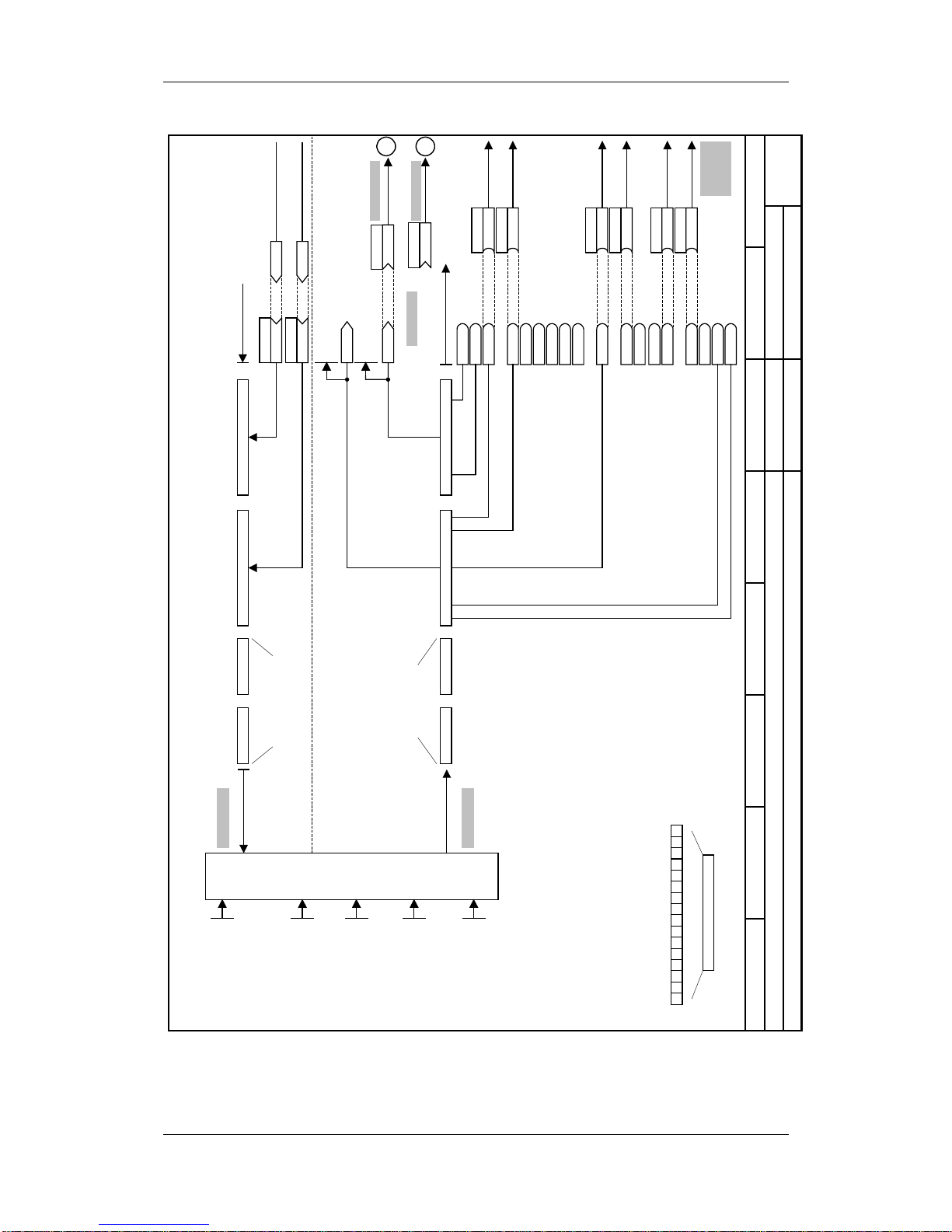
Parameterizing Steps 05.2003
6SE7087-6JP60 Siemens AG
9-16 Operating Instructions SIMOVERT MASTERDRIVES
87654321
Setpoint source
MASTERDRIVES VCPROFI BUS 1st CB (P368=6)
- s6 -
P572.1
B (3112)
B3115 External fault
Src Neg. Spd
B3114 Raise MOP
B3110 PcD control
B3112 Negative Spd
P571.1
B (3111)B3111 Positive Spd
B3109 Jog Bit1
P568.1
B (3108)B3108 Jog Bit0
P566.1
B (3107)B3107 Acknowledge
B3106 Setpoint Release
B3105 No RGen Stop
B3104 RGen Release
B3103 Inv. Release
B3102 OFF3 (QStop)
P555.1
B (3101)B3101 OFF2 (electr.)
B3215
Src Pos Spd
Src Jog Bit0
Src 2 Acknow
Src OFF2
B3200
Bit0
up to Bit15
K3002
P486.B
K
Src T setpoint
1. CB Word2
r733.2
P443.B
K (3002)
Main setpoint
K3001
1. CB Word1
r733.1
P734.1(32)
K
K0032
ZUW1
r552
Status word
from sheett
[200]
P734.2
K
KK0148
n/f(act)
from sheet
[350.7], [351.7]
[352.7], [400.7]
Transmit actual values
Receive setpoints
Bit15
Bit14
PKW PKW PZD1 (Data word1) PZD2 (Data word 2)
PKW PKW PcD1 (Data word 1) PZD2 (Data word 2)
Control word
B3100 ON/OFF1
Bit0
Bit1
Bit7
Reserved for write operations of
parameter data
===•
Reserved for read
operations of
parameter data
Sheet [125]
Sheet [120]
B3113 Raise MOP
For T control:
===•==•==•==•==•
•
===•==•==•==•==•
•
to sheet [180]
control word 1
r550
===•
PcD1 (Data word1)
Reserve
pos./neg. speed setp
Ramp-function gen. active
Energize main cont.
Undervoltage fault
Comp. Setp reached
PZD control
Set/actual deviation
Alarm effective
Switch-on ihibit
OFF3 effe ctive
OFF2 effe ctive
Fault effective
Operation
Ready
Ready for ON
15 0
1
ZUW1
P554.1
B (3100)
Src ON/OFF1
Receive
Transmit
to sheet [316.1]
to sheet [320.1]
N
M
CB
configu-
ration
CB Parameter 1
0 ... 65535
P711.01
CB Parameter 10
0 ... 65535
P720.01
CB Parameter 11
0 ... 65535
P721.01 to .05
CB/TB TlgOFF
0 ... 6500 ms
P722.01 (10)
P722.01 =0 :
No monitoring
CB Bus Address
0 ... 200
P918.01 (3)
•=•=•=•=•=•
•=•=•=•=•=•
Aotewell Ltd
www.aotewell.com
Industry Automation
HongKong|UK|China
sales@aotewell.com
+86-755-8660-6182
Page 87

05.2003 Parameterizing Steps
Siemens AG 6SE7087-6JP60
SIMOVERT MASTERDRIVES Operating Instructions 9-17
87654321
Setpoint source
MASTERDRIVES VCOP1S and fixed setpoints (P368=7)
- s71 -
KK0046
KK0045
KK0047
KK0048
KK0040
Act.FSetp
Active FSetp
r420
P443.B (40)
KK
Src Main Setpoint
P486.B (40)
KK
Src T setpoint
0 1 0 0
0 1 0 1
0 1 1 0
0 1 1 1
FSetp
Bit 3
P418.B
FSetp
Bit 2
P417.B
0 0 0 0
0 0 0 1
0 0 1 0
0 0 1 1
KK0042
KK0041
KK0043
KK0044
(for T control)
Fixed setpoint1
P401.F
Fixed setpoint2
P402.F
Fixed setpoint3
P403.F
Fixed setpoint4
P404.F
Fixed setpoint5
P405.F
Fixed setpoint6
P406.F
Fixed setpoint7
P407.F
Fixed setpoint8
P408.F
in %
in Hz
Fixed
setpoints
Sheet [290]
Terminal strip
Sheet [90]
If used as digital inputs , the parameters
P651.B, P652.B, P653. B and P654.B must
be set to 0!
If used as digital outputs, B10 to B14 must
not be wired.
*
)
from sheet [200]
to sheet [180]
to sheet[316.1]
to sheet[320.1]
N
M
n959.89 = 4
If P366 = 2
P590 = B0012
P651 = B0000
P652 = B0000
P653 = B0107
/5
/4
/3
/2
/1
B0014
P653.1 (0)
B
B0012
P652.1 (104)
B
B0010
P651.1 (107)
B
M24
P24
-X101
B0104
B0107
Operation
0=fault
*
)
*
)
1=operation
No fault
*
)
P590 (14)
B
Src BICO DSet
See P049.4
FSetp
Bit 1
P581.B
FSetp
Bit 0
P580.B
(for T control)
(for n/f control or v/f control)
Aotewell Ltd
www.aotewell.com
Industry Automation
HongKong|UK|China
sales@aotewell.com
+86-755-8660-6182
Page 88

Parameterizing Steps 05.2003
6SE7087-6JP60 Siemens AG
9-18 Operating Instructions SIMOVERT MASTERDRIVES
87654321
Setpoint source
MASTERDRIVES VCOP1S and fixed setpoints at USS2 (P368=7)
- s72 -
P572.1
B (6112)
B6115 External fault
Src negative spd
B6114 Lower MOP
B6110 PcD control
B6112 Negative Spd
P571.1
B (6111)B6111 Positive Spd
B6109 Jog Bit1
P568.1
B (6108)B6108 Jog Bit0
P565.1
B (6107)B6107 Acknowledge
B6106 Setp Release
B6105 No RGen Stop
B6104 RGen Release
B6103 Inv Release
B6102 OFF3 (QStop)
B6101 OFF2 (electr.)
B6215
Src positive spd
Src Jog Bit0
Src1 Acknow.
B6200
Bit0
bis Bit15
K6002
P486.B
K
Src T setpoint
SCom2Word2
r709.18
P443.B
K (6002)
Main setpoint
K6001
SCom2Word1
r709.17
P708.1
K
K0032
ZUW1
r552
Status word 1
from sh.
[200]
P708.2
K
KK0148
n/f(act)
from sh.
[350.7], [351.7]
[352.7], [4 00.5]
Transmit actual values
Receive setpoints
Bit15
Baud rate
P701.2
PKW #
P702.2
PcD #
P703.2
PKW:127
PcD: 2
Baud rate:
9.6 kB
PKW PKW PcD1 (Data word1) PcD2 (Data word 2)
PKW PKW PcD1 (Data word1) PcD2 (Data word 2)
Control word 1
B6100 ON/OFF1
Bit0
Bit1
Bit7
Reserved for write operations of
parameter data
===
•
Reserved for read
operations of
parameter data
Sheet [101]
Sheet [111]
P700.2 = Bus address
P704.2 = Tlg failure time
B6113 Raise MOP
for T control:
===•==•==•==•==•
•
===•==•==•==•==•
•
to sheet [180]
control word 1
r550
/3
RS485P
/8
RS485N
===
•
Setpoint via process data
(only DriveMonitor):
Reset
I O
Bit8
Jog
Bit11
Bit12
P049 = OP operating display
OP1S keys
P554.1
B (6100)
Src ON/OFF1
to sh. [320.1]
-X103
Receive
Transmit
to sh. [316.1]
N
M
n957.88 = 4
PZD1 (Data word1)
Reserve
pos./neg. speed setp
Ramp-function gen. active
Energize main cont.
Undervoltage fault
Comp. setpoint reached
PcD cont rol
Set/actual deviation
Alarm effective
Switch-on inhibit
OFF3 effective
OFF2 effective
Fault effective
Operation
Ready
Ready for ON
15 0
1
ZUW1
Only applicable for Compact PLUS!
Aotewell Ltd
www.aotewell.com
Industry Automation
HongKong|UK|China
sales@aotewell.com
+86-755-8660-6182
Page 89

05.2003 Parameterizing Steps
Siemens AG 6SE7087-6JP60
SIMOVERT MASTERDRIVES Operating Instructions 9-19
87654321
Setpoint source
MASTERDRIVES VCOP1S and MOP at USS2 (P368=8)
- s82 -
P572.1
B (6112)
B6115 External fault
B6114 Lower MOP
B6110
PcD control
B6112 Negative Spd
P573.1
B (6113)
B6111 Positive Spd
B6109 Jog Bit1
B6108 Jog Bit0
P565.1
B (6107)B6107 Acknowledge
Src Raise MOP
Bit0
bis Bit15
K6002
P486.B
K
Src T setpoint
SST2Word2
r709.18
P443.B
K (6002)
Main setpoint
K6001
SST2Word1
r709.17
P708.1
K
K0032
ZUW1
r552
Status word 1
from sh.
[200]
P708.2
K
KK0148
n/f(act)
Bit15
Baudrate
P701.2
PKW #
P702.2
PZD #
P703.2
PKW:127
PZD: 2
Baud rate:
9.6 kB
PKW PKW
PcD1 (Data word 1) PcD2 (Data word 2)
PKW PKW
PcD1 (Data word1) P cD2 (Data word2)
Control word 1
Bit0
Bit1
Bit7
===•
Sheet [101]
Sheet [111]
B6113 Raise MOP
•==•==•==•==•==•
to sh. [180]
Control word 1
r550
/3
RS485P
/8
RS485N
===•
Reset
I O
Bit8
Jog
Bit11
Bit12
OP1S-keys
P554.1
B (6100)
-X103
Receive
Transmit
N
M
n957.90 = 4
P574.1
B (6114)
Src Lower MOP
•==•==•==•==•
Reserved for write operations of
parameter data
Reserved for read
operations of
parameter data
Transmit actual values
Setpoint via process data
(only DriveMonitor):
to sh. [316.1]
to sh. [320.1]
for T control:
from sh.
[350.7], [351.7]
[352.7], [400.5]
Receive setpoints
Src ON/OFF1
Src1 Acknow.
Src negative spd
B6106
Setp Release
B6105 No RGen Stop
B6104 RGen Release
B6103
Inv Release
B6102
OFF3 (QStop)
B6101 OFF2 (electr.)
B6215
B6200
B6100 ON/OFF1
P700.2 = Bus address
P704.2 = Tlg failure time
PZD1 (Data word1)
Reserve
pos./neg. speed setp
Ramp-function gen. active
Energize main cont.
Undervoltage fault
Comp. setpoint reached
PcD control
Set/actual deviation
Alarm effective
Switch-on inhibit
OFF3 effective
OFF2 effective
Fault effective
Operation
Ready
Ready for ON
15 0
1
ZUW1
P049 = OP operating display
Only applicable for Compact PLUS!
Aotewell Ltd
www.aotewell.com
Industry Automation
HongKong|UK|China
sales@aotewell.com
+86-755-8660-6182
Page 90

Parameterizing Steps 05.2003
6SE7087-6JP60 Siemens AG
9-20 Operating Instructions SIMOVERT MASTERDRIVES
87654321
Setpoint source
MASTERDRIVES VCOP1S and MOP (P368=8)
- s83 -
Terminal strip
Sheet [90]
P
I O
B6100
P554.1
(22)
B
ON/OFF 1 Src ON/OFF1
B6113
P573.1
(8)
B
Raise MOP
B6114
P574.1
(9)
B
Lower MOP
Src Raise MOP
Src Lower MOP
n959.91 = 4
/5
/4
/3
/2
/1
B0014
P653.1 (0)
B
B0012
P652.1 (104)
B
B0010
P651.1 (107)
B
M24
P24
-X101
B0104
B0107
operation
0=fault
*
)
*
)
1=operation
no fault
*
)
P590 (14)
B
Src BICO DSet
B6107
P565
B
1 Acknowledge
Src1 Acknowledge
B6112
P572
B
Negative Spd
Src Negative Spd
MOP MP Sheet [300]
Accel Time MOP
P431
P443.B (58)
KK
Src Main Setpoint
MOP(Outp.)
r424
P425
Conf MOP
KK058
MOP(Outp.)
P486.B (58)
KK
Src T Setpoint
(for T control )
Decel Time MOP
P432
MOP (max)
P421
P422
MOP (min.)
0xx0 = ... without storing after OFF
0xx1 = ... storing after OFF
Raise MOP
Lower MOP
to sheet [316.1]
to sheet [320.1]
N
M
to sheet [180]
from sheet [200 ]
Only applicable for Compact PLUS!
Aotewell Ltd
www.aotewell.com
Industry Automation
HongKong|UK|China
sales@aotewell.com
+86-755-8660-6182
Page 91

05.2003 Parameterizing Steps
Siemens AG 6SE7087-6JP60
SIMOVERT MASTERDRIVES Operating Instructions 9-21
87654321
Analog outputs and display variables
MASTERDRIVES VC
- a0-
DC Link Volts
r006
K0025
DC Link Volts
K0240
UZk(ist)
Torque
r007
K0024
Torque
K0241
T(act)
Output power
K0023
Output power
Output Amps
r004
K0022
Output Amps
K0242
I(Output Amps)
Output voltage
K0021
Output voltage
K0204
U(set,v/f)
2s
30 ms
2s
2s
Rot Freq
r002
KK020
Actual speed
KK148
n/f(act)
2s
Actual Speed
r015
n/f (act)
r218
P640.1
K (148)
Src Analog Output
Sheet [81]
x
y(v) = x / 100% * P643
y
D
A
+/- 10 V
-X102/19
-X102/20
AA1
P640.2
K (22)
Src Analog Output
x
y(v) = x / 100% * P643
y
D
A
+/- 10 V
-X102/21
-X102/22
AA2
AA1 Scaling
P643.1
AA2 Scaling
P643.2
AA1 Offset
P644.1
AA2 Offset
P644.2
Display variables Analog outputs
1
2
3
Switch S4
0 ... 20 mA
4
5
6
Switch S4
0 ... 20 mA
Sheet [30]
P038.x
K
K
%
.01
.02
Display torque
r039.1 to .2
Reference torque
P354
P040.x
K
K rpm
.01
.02
Display speed
r041.1 to .3
Reference speed
P353
K
.03
P042.x
K
K Hz
.01
.02
Display frequency
r043.1 to .3
Reference frequency
P352
K
.03
from sheet
[350.7]
[351.7]
[352.7]
[400.5]
Display parameters
Explanations:
Sheet [300]:
See Compendium sheet 300
from sheet
[285.3]
[286.3]
from sheet
[285.3]
[286.3]
from sheet
[285.7]
[286.7]
from sheet
[285.7]
from sheet
[285.3]
[286.3]
*
)
Torque display only with n/f/T control
*
)
*
)
*
)
*
)
5 - 62 - 3
4 - 61 - 3
Switches on CUVC S4:
-10 V ... 10 V
0 mA ... 20 mA
AA1 AA2
*
)
2
Reference to the current path of
r
XX
sheets
4
3
6
1
n959.80 = 3
Note concerning the setting of analog outputs:
B = Reference variable (c.f. P350 ... P354)
S
min
= smallest signal value (e.g. in Hz, V, A)
S
max
= largest signal value (e.g. in Hz, V, A)
A
min
= smallest output value in V
A
max
= largest output value in V
Output values applying to output current:
4 mA A
min
= + 6 V
20 mA A
max
= - 10 V
P643 =
A
max
ϑ A
min
S
max
ϑ S
min
x B
P644 =
A
min
x S
max
ϑ
A
max
x S
min
S
max
ϑ S
min
<1>
<1> Only applicable for Compact/Chassis type unit,
for Compact PLUS Sheet [82] is applicable
Aotewell Ltd
www.aotewell.com
Industry Automation
HongKong|UK|China
sales@aotewell.com
+86-755-8660-6182
Page 92

Parameterizing Steps 05.2003
6SE7087-6JP60 Siemens AG
9-22 Operating Instructions SIMOVERT MASTERDRIVES
87654321
V/f characte ristic with spee d controller (P100=0)
MASTERDRIVES VC
- r0 -
Imp.tach.
Ana.tach.
X104
23 Tacho M
24 Track A
25 Track B
26 Zero track
27 Control tr.
28 Tacho P15V
Normalization
Motor encoder
P130.M (11) *
)
Pulse #
P151.M (1024) *
)
KK148
n/f(act)
n/f(act)
r218
Smooth. n/f(act)
P223.M
P443.B
KK
Src main setpoint
P462.F (10s)
Accel Time
P464.F (10s)
Decel Time
n/f(set)
r482
n/f(set,smooth)
r229
P453.F (-110.0%) *
)
n/f(max,neg.Spd)
n/f(max,pos.spd)
P452.F (110 .0 % ) *
)
–
KK0188
f(Slip)
Volts
mod
depth
Asyc.
Mot. 3~
KK199
f(set,stator)
Smooth. vd(act)
P287.M
Setpoint channel Speed controller Speed limitation controller v/f characteristic Gating unit
Sheet 352Sheet 250
Sheet 316 Sheet 317 Sheet 364 Sheet 401 Sheet 405 Sheet 286
Motor
encoder
P138.M (3000)
Ana.TachScale
KK075
r014
Setpoint speed
Sheet 318
Current
Lim.
r129
–
P235.M
n/f-Reg.Gain1
P240.M
n/f-Reg.Tn
Boost End
Freq
P326.M
Mot.Freq.(n)
P107.M (50) *
)
Field Weak
Freq
P293.M
Mot.voltage
P101.M *
)
FSetp Boost
P325.M
Maximum
current
P128.M
Imax-Ctrl Gain
P331.M
Imax-Ctrll.Tn
P332.M
max.Outp Volts
r346
P330.M
Src SelCurve *
)
KK091
n/f(act,encoder)
P433.B (0)
KK
Srce AddSetp1
Ref.
Frequency: P352 *)Speed: P353 *
)
*
)
Parameter only adjustable in the "Drive setting" state (P60=5)
–
–
Output
current
Explanations:
Sh. [300]
: See Compendium Sheet 300
: Reference to setpoint source (see s
XX
-sheets)
N
M
1
: Reference to current path sheet "a0"
"Analog outputs and display variables"
3
6
4
2
N
n957.85 = 0
Aotewell Ltd
www.aotewell.com
Industry Automation
HongKong|UK|China
sales@aotewell.com
+86-755-8660-6182
Page 93

05.2003 Parameterizing Steps
Siemens AG 6SE7087-6JP60
SIMOVERT MASTERDRIVES Operating Instructions 9-23
87654321
V/f characteristic (P100=1)
MASTERDRIVES VC
- r1 -
P443.B
KK
Src main setpoint
P462.F (10 s)
Accel time
P464.F (10 s)
Decel time
n/f(set)
r482
n/f(set,smooth)
r229
P453.F (-110.0%) *
)
n/f(max,neg.spd)
n/f(max,pos.spd)
P452.F (110,0%) *
)
KK188
f(Slip)
Volt.
Mod.
Depth
Asyc.
Mot. 3~
KK199
f(set,Stator)
Smooth vd(act)
P287.M
Setpoint channel Current limitation controller V/f characteristic Gating unit
Sheet 316 Sheet 317 Sheet 400 Sheet 405 Sheet 286
KK075
r014
Setpoint speed
Sheet 318
Current
lim.
r129
–
Slip comp Kp
P336.M (0)
Boost end
frequency
P326.M
Mot.Freq.(n)
P107.M (50) *
)
Field weak.
frequency
P293.M
Mot. Volts
P101.M *
)
FSetp Boost
P325.M
Maximum
current
P128.M
Imax controller Tn
P332.M
–
n/f(ist)
r218
KK148
max.Outp Volts.
r346
Imax controller Kp
P331.M
P330.M
Src Select Char.
P433.B (0)
KK
Src add. setp.1
Ref,
frequency: P352 *)speed: P353 *
)
*
)
Parameter only adjustable in the "Drive set t i ng" s t at us (P60=5)
–
Output Amps
N
4
2
6
3
n957.86 = 0
Aotewell Ltd
www.aotewell.com
Industry Automation
HongKong|UK|China
sales@aotewell.com
+86-755-8660-6182
Page 94

Parameterizing Steps 05.2003
6SE7087-6JP60 Siemens AG
9-24 Operating Instructions SIMOVERT MASTERDRIVES
87654321
V/f characteristic (P100=2)
MASTERDRIVES VCTextile
- r2 -
P443.B
KK
Src main setpoint
P462.F (10 s)
Accel Time
P464.F (10 s)
Decel Time
n/f(set)
r482
n/f(set,smooth)
r229
P453.F (-110,0%) *
)
n/f(max,neg.spd)
n/f(max,pos.spd)
P452.F (110,0%) *
)
Volt.
Mod.
Depth
Asyc.
Mot. 3~
KK199
f(set,stator)
Smooth Vd(act)
P287.M
Setpoint channel Current limitation controller V/f characteristic Gating unit
Ref.
frequency: P352 *)speed: P353 *
)
Sheet 316 Sheet 317 Sheet 402 Sheet 405 Sheet 286
KK075
r014
Setpoint speed
Sheet 318
Current
lim.
r129
–
Boost end
frequency
P326.M
Mot.Freq.(n)
P107.M (50) *
)
Field weakening
frequency
P293.M
Mot.voltage
P101.M *
)
FSetp boost
P325.M *
)
Maximum
currents
P128.M
Imax controller Tn
P332.M
n/f(act)
r218
KK148
max.outp. volts
r346
Imax controller Kp
P331.M
P438.B (0)
KK
Src Add Setp2
P433.B (0)
KK
Src AddSetp.1
*
)
Parameter can only be adjusted in the "Drive setting" status (P60=5)
–
P330.M
Src Select Char.
Output Amps
N
2
3
6
4
n957.87 = 0
Aotewell Ltd
www.aotewell.com
Industry Automation
HongKong|UK|China
sales@aotewell.com
+86-755-8660-6182
Page 95

05.2003 Parameterizing Steps
Siemens AG 6SE7087-6JP60
SIMOVERT MASTERDRIVES Operating Instructions 9-25
87654321
Closed-loop speed control without encoder (frequency control) P100=3
MASTERDRIVES VCMaster drive (P587 = 0)
- r3 -
P127.M (80%)
R(rotor)Ktmp
KK148
n/f(ist)
n/f(ist)
r218
Smooth.n/f(act)
P223.M
P443.B
KK
Src main setpoint
P462.F (10 s)
Accel Time
P464.F (10 s)
Decel Time
n/f(set)
r482
n/f(set,smooth)
r229
P453.F (-110,0%) *
)
n/f(max,neg.spd)
n/f(max,pos.spd)
P452.F (110,0%) *
)
–
P235.M
n/f-Reg.Kp1
K0155
i-Anteil
K0153
Msoll,reg
Scal.T(pre)
P471.M (0)
K0165
T(set,limitr)
r269
x
y
Volt.
Mod.
Depth
Asyc.
Mot. 3~
Torque limitation
P240.M
n/f-Reg.Tn
P339.M *
)
ModSystem
Release
Tn
P284.M
Kp
P283.M
K0184
Isq(act)
Kp
P283.M
Tn
P284.M
Isd (act)
–
–
K0168
Isq(set)
+
KK188
Slip frequency
Current
model
EMF
model
KK199
f(set,stator)
–
P315.M
EMF Reg.Kp
P316.M
EMF-Reg.Tn
Smooth Vd(act)
P287.M
Setpoint channel Speed controller Torque/current limit Current controller Gating unit
Note:
The current injection of
P278 T(droop) (Fig. 382)
is only calculated for
frequencies below approx. 10%
of the rated motor frequency.
Sheet 316 Sheet 317 Sheet 319 Sheet 362 Sheet 367 Sheet 372 Sheet 390
Sheet 381
Sheet 396
Sheet 285
KK075
r014
Setpoint speed
+
Sheet 318
K0172
TorqLimit1,act
K0173
TorqLImit2,act
P433.B (0)
KK
Src Add. Setp1
Sheet 351
P499.B (171)
K
Src TorqLimit2
K171
P493.B (170)
K
Src TorqLimit1
Src TorqLimit1 FSetp
P492.F (100%)
K170
Src TorqLimit2 FSetp
P498.F (-100%)
Sheet 382
*
)
Parameter can only be
changed in the "Drive setting"
status (P60=5)
i-comp.
max.mod. depth r346
ModDepth Headrm
P344.M
Field weak. charac.
T(droop) P278.M
T(dynam.) P279.M
Smoothing I(set) P280.M
Start-up time
P116.M
Pw,max(gen)
P259.M
r129
Ref.
frequency: P352 *)
speed: P353 *)
torque: P354 *)
P354 is referred to
P113 *)
N
3
6
2
n957.88 = 0
Maximum current
P128.M
Aotewell Ltd
www.aotewell.com
Industry Automation
HongKong|UK|China
sales@aotewell.com
+86-755-8660-6182
Page 96

Parameterizing Steps 05.2003
6SE7087-6JP60 Siemens AG
9-26 Operating Instructions SIMOVERT MASTERDRIVES
87654321
Closed-loop speed control without encoder (frequency control) P100=3
MASTERDRIVES VCSlave drive (P587 = 1)
- r31 -
P127.M (80%)
R(rotor)Ktmp
KK148
n/f(act)
n/f(act)
r218
Smooth.n/f(act)
P223.M
n/f(setl,smooth)
r229
–
P235.M
n/f-Reg.Kp1
K0155
i-comp.
K0153
Tset,reg
K0165
M(set,limitr)
r269
x
y
Volt.
Mod.
Depth
Asyc.
Mot. 3~
Torque limitation
P240.M
n/f-Reg.Tn
P339.M *
)
ModSystem
Release
Tn
P284.M
Kp
P283.M
K0184
Isq(act)
Kp
P283.M
Tn
P284.M
Isd (act)
–
–
max.Ausg.spg. r346
ModDepth Headrm
P344.M
Field weak. charac.
K0168
Isq(set)
+
KK188
Slip frequency
Current
model
EMF
Model
KK199
f(set,Stator)
–
P315.M
EMF Reg Gain
P316.M
EMF Reg.Tn
Smooht. Vd(act)
P287.M
Maximum
current
P128.M
Pw,max(gen)
P259.M
Setpoint channel Speed controller Torque/current limit Current controller Gating unit
Sheet 320 Sheet 363 Sheet 372 Sheet 390
Sheet 381
Sheet 396
Sheet 285
r014
setpoint speed
+
K0172
TorqLimit1,act
K0173
TorqLimit2, act
T(droop) P278.M
T(dynam.) P279.M
Sheet 351
Sheet 382
P486.B
K
Src Torq Setp
n/f(soll)
r482
P453.F (-110,0%) *
)
n/f(max,neg.spd)
n/f(max,pos spd)
P452.F (110 %) *
)
KK075
TorqLimit1 FSetp
P492.F (100%)
Mgrenz2 FSW
P498.F (-100%)
TorqLimit1
r496
r502
Mgrenz2
-1
T-add. FSetp
P505.F (0.0)
Start-up time
P116.M (~)
SmoothingI (set) P280.M
Ref.
frequency: P352 *)
speed: P353 *)
torque: P354 *)
P354 is referred to
P113 *)
*
)
Parameter can only be
changed in the "Drive setting"
status (P60=5)
M
6
3
2
n957.89 = 0
Aotewell Ltd
www.aotewell.com
Industry Automation
HongKong|UK|China
sales@aotewell.com
+86-755-8660-6182
Page 97

05.2003 Parameterizing Steps
Siemens AG 6SE7087-6JP60
SIMOVERT MASTERDRIVES Operating Instructions 9-27
87654321
Closed-loop speed control (P 100=4)
MASTERDRIVES VCMaster drive (P587 = 0)
- r4 -
Imp.tach.
Ana.tach.
X104
23 Tacho M
24 Track A
25 Track B
26 Zero track
27 Control track
28 Tacho P15V
Normalization
P127.M (80%)
R(rotor)Ktmp
Motor encoder
P130.M (11) *
)
Pulse #
P151.M (1024) *
)
KK148
n/f(ist)
n/f(act)
r218
Smooth.n/f(pre)
P216.M
Smooth n/f(act)
P223.M
P443.B
KK
Src main setpoint
P462.F (10 s)
Accel Time
P464.F (10 s)
Decel Time
n/f(set)
r482
n/f(set,smooth)
r229
P453.F (-110,0%) *
)
n/f(max,neg.spd)
n/f(max,pos.spd)
P452.F (110,0%) *
)
–
P235.M
n/f-Reg.Kp1
K0155
i-Anteil
K0153
Msoll,reg
Scal.Torq(pre.)
P471.M
P438.B (0)
KK
Src Add Setp2
K0165
T(set,limitr)
r269
x
y
Volt.
Mod.
Depth
Asyc.
Mot. 3~
Torque limitation
P240.M
n/f-Reg.Tn
P339.M *
)
ModSystem
Release
Tn
P284.M
Kp
P283.M
K0184
Isq(act)
Kp
P283.M
Tn
P284.M
Isd (act)
–
–
max.outp.volt.
r346
ModDepth Headrm
P344.M
Field weakening
characteristic
K0168
Isq(set)
+
KK188
Slip frequency
Current
model
EMF
Model
KK199
f(set,Stator)
–
P315.M
EMF Reg Gain
P316.M
EMF Reg.Tn
Smooth Vd(act)
P287.M
Setpoint channe l Speed cont roller Torq ue/current limit Current controller Gating unit
Sheet 350Sheet250
Sheet 316 Sheet 317 Sheet 319 Sheet 360 Sheet 365 Sheet 370 Sheet 390
Sheet 380
Blatt 395
Sheet 285
Motor
encoder
P138.M (3000)
Ana.TachoComp
KK075
r014
Setpoint speed
+
Sheet 318
K0172
TorqLimit1,act
K0173
TorqLimit2,act
P433.B (0)
KK
Src Add Setp.1
P499.B (171)
K
Src TorqLimit2
K171
P493.B (170)
K
Src TorqLimit1
TorqLimit1 FSetp
P492.F (100%)
K170
TorqLimit2 FSetp
P498.F (-100%)
*
)
Parameter can only be changed in the "Drive setting" status P60=5
KK091
n/f(act,encoder)
Start-up time
P116.M
Maximum cur r ent
P128.M
Pw,max(gen)
P259.M
r129
Ref.
frequency: P352 *)
speed: P353 *)
torque: P354 *)
P354 is referr e d to
P113 *)
N
3
6
2
n957.90 = 0
Aotewell Ltd
www.aotewell.com
Industry Automation
HongKong|UK|China
sales@aotewell.com
+86-755-8660-6182
Page 98

Parameterizing Steps 05.2003
6SE7087-6JP60 Siemens AG
9-28 Operating Instructions SIMOVERT MASTERDRIVES
87654321
Closed-loop speed control / torque c ontrol (P100=4/5)
MASTERDRIVES VCSlave drive (P587 = 1)
- r5 -
IPulse tach.
Ana.tach.
X104
23 Tacho M
24 Track A
25 Track B
26 Zero track
27 Control track
28 Tacho P15V
Normalization
P127.M (80%)
R(rotor)Ktmp
Motor encoder
P130.M (11) *
)
Pulse
P151.M (1024) *
)
KK148
n/f(act)
n/f(act)
r218
Smooth.n/f(FWD)
P216.M
Smooth n/f(act)
P223.M
P486.B
K
Src Torque Setp
n/f(set)
r482
n/f(set, smooth)
r229
P453.F (-110,0%)
n/f(max,neg.spd) *
)
–
P235.M
n/f-Reg.Kp1
K0155
i-comp.
K0153
Tset,reg
n/f(max,pos spd)
P452.F (110 %) *
)
K0165
M(set,limitr)
r269
x
y
Volt.
Mod.
Depth
Asyc.
Mot. 3~
Torque limitation
P240.M
n/f-Reg.Tn
P339.M *
)
Pulse system
release
Tn
P284.M
Kp
P283.M
K0184
Isq(act)
Kp
P283.M
Tn
P284.M
Isd (act)
–
–
max.outp . vo l ts
r346
ModDepth Headrm
P344.M
Field weakening
characteristic
K0168
Isq(set)
+
KK188
Slip frequency
Current
model
EMF
model
KK199
f(set, stator)
–
P315.M
EMF Reg Gain
P316.M
EMF-Reg Tn
Smooth. Vd(a ct)
P287.M
Maximum current
P128.M
Pw,max(gen)
P259.M
Setpoint channel
Speed limitation
controller Torque/current limit Current controller Gating unit
Ref.
frequency: P352 *)
speed: P353 *)
torque: P354 *)
P354 is referred to P113 *)
Sheet 350Sheet 250
Sheet 320 Sheet 361 Sheet 371 Sheet 390
Sheet 380
Sheet 395
Sheet285
Motor
encoder
P138.M (3000)
Ana.TachoComp
KK075
r014
Setpoint speed
+
K0172
TorqLimit1,act
K0173
TorqLimit2,act
TorqLimit1 FSetp
P492.F (100%)
P498.F (-100%)
TorqLimit2 FSetp
TorqLimit1
r496
r502
TorqLimit2
-1
Torq Add. FSetp
P505.F (0.0)
KK091
n/f(act,encoder)
*
)
Parameter can only be changed in the "Drive setting" status (P60=5)
M
3
6
2
n957.91 = 0
Aotewell Ltd
www.aotewell.com
Industry Automation
HongKong|UK|China
sales@aotewell.com
+86-755-8660-6182
Page 99

05.2003 Maintenance
Siemens AG 6SE7087-6JP60
SIMOVERT MASTERDRIVES Operating Instructions 10-1
10 Maintenance
SIMOVERT MASTERDRIVES units are operated at high voltages.
All work carried out on or with the equipment must conform to all the
national electrical codes (VBG 4 in Germany).
Maintenance and service work ma y only be execute d by qualified
personnel.
Only spare parts authorized by the manufacturer may be used.
The prescribed maintenance intervals and also the instructions for
repair and replacement must be complied with.
Hazardous voltages are still present in the drive units up to 5 minutes
after the converter has been powered down due to the DC link
capacitors. Thus, the unit or the DC link terminals must not be worked
on until at least after this delay time.
The power terminals and control terminals can still be at hazardous
voltage levels even when the motor is stationary.
If it is absolutely necessary that the drive converter be worked on when
powered-up:
♦ Never touch any live parts.
♦ Only use the appropriate measuring and test equipment and
protective clothing.
♦ Always stand on an ungrounded, isolated and ESD-compatible pad.
If these warnings are not observed, this can result in death, severe
bodily injury or significant material damage.
10.1 Replacing the fan
A fan is mounted at the lower section of the inverter for cooling the
power section.
The fan is fed by the 24 V supply voltage and switched on and off by
electronic control according to the heat sink temperature.
The fan is designed for a service life of L
10
≥ 35,000 hours and an
ambient temperature of
T
u
= 45 °C. It must be exchanged in good time to ensure the availability
of the unit.
DANGER
Aotewell Ltd
www.aotewell.com
Industry Automation
HongKong|UK|China
sales@aotewell.com
+86-755-8660-6182
Page 100

Maintenance 05.2003
6SE7087-6JP60 Siemens AG
10-2 Operating Instructions SIMOVERT MASTERDRIVES
10.1.1 Replacing the fan in units up to 45 mm wide
To replace the fan, the inverter has to be disconnected from the supply
and removed.
After removing the X20 connector which is protected against polarity
reversal and undoing the two cover screws, unscrew the fan and
withdraw the connector.
Fit the fan in the reverse order, making sure that the arrow indicating
the direction of air flow points to the inside of the unit.
Make sure that the leads to the fan are connected the right way round.
Otherwise the fan will not operate!
10.1.2 Replacing the fan in units up to 90 mm wide
To replace the fan, the inverter has to be disconnected from the supply
and removed.
After removing the X20 connector which is protected against polarity
reversal and unscrewing the two cover screws, the fan can be
dismantled by pushing out the interna ls of the inser t rive ts and the
connector can be disconnected. The insert rivets can be re-used.
Fit the fan in the reverse order, making sure that the arrow indicating
the direction of air flow points to the inside of the unit.
Make sure that the leads to the fan are connected the right way round.
Otherwise the fan will not operate!
Removal
DANGER
Installation
DANGER
Removal
DANGER
Installation
DANGER
Aotewell Ltd
www.aotewell.com
Industry Automation
HongKong|UK|China
sales@aotewell.com
+86-755-8660-6182
 Loading...