

Page 1

SIMOREG DC Master
6RA70 Series Base Drive Instructions
Microprocessor-based converters from 15A to 1680A
for variable speed DC drives
Rev6.0
dc drives
Global network of innovation
Page 2

Converter software version:
As these Operating Instructions went to print, SIMOREG 6RA70 DC Master converters were being delivered
from the factory with software version 2.2 installed.
These Operating Instructions also apply to other software versions.
Earlier software versions: Some parameters described in this document might not be available in the software
(i.e. the corresponding functionality is not available on the converter) or some
parameters will have a restricted setting range. SIMOREG 6RA70 Base Drive Panel
series requires software version 1.8 or later.
Later software versions: Additional parameters might be available on the SIMOREG DC Master (i.e. extra
functions might be available which are not described in these Operating Instructions)
or some parameters might have an extended setting range. In this case, leave the
relevant parameters at their factory setting, or do not set any parameter values which
are not described in these Instructions !
The latest software version of the SIMOREG DC Master can be read in parameters r060 and r065.
The latest software version is available at the following Internet site:
http://www4.ad.siemens.de/view/cs/en/8467834
The reproduction, transmission or use of this document or contents is
not permitted without express written authority. All rights, including
rights created by patent grant or registration of a utility model or design,
are reserved.
We have checked that the contents of this publication agree with the
hardware and software described herein. Nonetheless, differences
might exist and therefore we cannot guarantee that they are completely
identical. The information given in this publication is reviewed at regular
intervals and any corrections that might be necessary are made in the
subsequent printings. Suggestions for improvement are welcome at all
times.
SIMOREG ® is a registered trademark of Siemens
© Siemens Energy & Automation 2006 All rights reserved
Page 3

0 Contents
Page
1 Safety information 1-1
2 Introduction
2.1 Base Drive Panel Description 2-1
2.2 General Information 2-1
2.3 Rated DC Current 2-2
2.4 Card Rack Assembly 2-2
3 Parts and Service
3.1 Base Drive Panel model numbers 3-1
3.2 Service 3-2
3.3 Option part numbers 3-3
3.4 Spare Parts 3-4
3.5 Standard Terms & Conditions 3-10
4 Receiving and Unpacking 4-1
5 Technical Data
5.1 15 to 100 ADC Base Drive Panels 5-1
5.2 140 to 850 ADC Base Drive Panels 5-2
5.3 1180 to 1680 ADC Base Drive Panels 5-3
5.4 Applicable Standards 5-5
6 Installation and Dimensions
6.1 Installation Information
6.2 Base Drive Panel Outlines 6-2
6-1
7 Base Drive Panel Connections
7.1 Base Drive Panel Schematics 7-2
7.2 Control Connections CUD1 7-16
7.3 Control Connections CUD2 7-18
7.4 Description of Power/Control Terminals 7-20
Siemens Energy & Automation 0-1
SIMOREG DC Master Base Drive Panel Operating Instructions
Page 4

8 Start-up
8.1 General safety information 8-1
8.2 Operator control panels 8-2
8.3 Parameterization procedure 8-4
8.4 Typical connection diagrams 8-6
8.5 Reset to factory default values 8-8
8.6 Start-up procedure 8-9
9 Faults and Alarms
9.1 Fault messages 9-1
9.2 Alarm messages 9-28
10 Abbreviated Parameter List
Overview 10-1
Overview of Abbreviations 10-3
10.1 Operating Status Display 10-5
10.2 General Visualization Parameters 10-7
10.3 Access Authorization Levels 10-11
10.4 Definition of SIMOREG Converter 10-13
10.5 Setting Values for Converter Control 10-17
10.6 Definition of Motor 10-22
10.7 Definition of Speed Sensing Pulse Encoder 10-27
10.8 Armature Current Control, Reversing, Gating 10-30
10.9 Current/Torque Limitation 10-32
10.10 Auto-reserving stage. Armature gating unit 10-34
10.11 Speed Controller 10-34
10.12 Field Current Control, Gating 10-36
10.13 Closed Loop EMF Control 10-38
10.14 Ramp Function Generator 10-39
10.15 Setpoint Processing 10-41
10.16 Ramp Function generator 10-42
10.17 Monitoring Functions and Limits 10-42
10.18 Limit-Value Monitors 10-43
10.19 Settable fixed values 10-45
10.20 Fixed control bits 10-46
10.21 Digital Setpoint Inputs 10-46
10.22 Position sensing with pulse encoder 10-48
10.23 Connector selector switches 10-49
0-2 Siemens Energy & Automation
SIMOREG DC Master Base Drive Panel Operating Instructions
Page 5

10.24 Motorized potentiometer 10-49
10.25 Oscillation 10-51
10.26 definition of Motor Interface 10-52
10.27 Torque Shell Input 10-53
10.28 Speed limiting controller 10-54
10.29 Friction compensation 10-54
10.30 Compensation of moment of inertia(dv/dt injection) 10-55
10.31 Speed controller 10-57
10.32 Field reversal 10-59
10.33 Input Quantities for Signals 10-59
10.34 Configuring of Closed-Loop Control 10-60
10.35 Control and Status Word 10-68
10.36 Further Configuring Measures 10-71
10.37 Analog Inputs 10-72
10.38 Analog Outputs 10-76
10.39 Binary Outputs 10-78
10.40 Configuration of Serial Interfaces 10-79
10.41 Deactivation of Monitoring Functions 10-89
10.42 Compensation values 10-89
10.43 Thyristor Diagnostics 10-90
10.44 Parameters for DriveMonitor and OP1S 10-90
10.45 Profile Parameters 10-90
10.46 Fault memory 10-91
10.47 Visualization parameters: Alarms 10-92
10.48 Device identification 10-93
10.49 Visualization parameters: Control and status word 10-93
10.50 Resetting and Storing Parameters 10-93
11 Simplified Block Diagrams 11-1
Siemens Energy & Automation 0-3
SIMOREG DC Master Base Drive Panel Operating Instructions
Page 6
1 Safety information
WARNING
Hazardous voltages and rotating parts are present in this electrical equipment during
operation. Non-observance of the safety instructions can result in death, severe
personal injury or substantial property damage.
Only qualified personnel should work on or around the equipment after first becoming
thoroughly familiar with all warning and safety notices and maintenance procedures contained
herein. The successful and safe operation of this equipment is dependent on proper handling,
installation, operation and maintenance.
Definitions:
• QUALIFIED PERSONNEL
For the purpose of this Instruction Manual and product labels, a "Qualified Person" is someone who
is familiar with the installation, construction and operation of the equipment and the hazards
involved. He or she must have the following qualifications:
1. Trained and authorized to energize, de-energize, clear, ground and tag circuits and equipment in
accordance with established safety procedures.
2. Trained in the proper care and use of protective equipment in accordance with established
safety procedures.
3. Trained in providing first aid.
• DANGER
For the purpose of this Instruction Manual and product labels, "Danger" indicates that death,
severe personal injury or substantial property damage will
taken.
• WARNING
For the purpose of this Instruction Manual and product labels, "Warning" indicates that death,
severe personal injury or substantial property damage can
taken.
• CAUTION
For the purpose of this Instruction Manual and product labels, "Caution" indicates that minor
personal injury or property damage can
result if proper precautions are not taken.
result if proper precautions are not
result if proper precautions are not
• NOTE
For the purpose of this Instruction Manual, "Note" indicates information about the product or the
respective part of the Instruction Manual which requires particular attention.
Siemens Energy & Automation 1-1
SIMOREG DC Master Base Drive Panel Operating Instructions
Page 7
NOTE
These operating instructions do not purport to cover all details or variations in equipment, nor to
provide for every possible contingency to be met in connection with installation, operation or
maintenance.
Should further information be desired or should particular problems arise which are not covered
sufficiently for the purchaser's purposes, the matter should be referred to the local Siemens
Sales Office.
The contents of these operating instructions shall not become part or modify any prior or existing
agreement, commitment or relationship. The Sales Contract contains the entire obligations of
Siemens. The warranty contained in the contract between the parties is the sole warranty of
Siemens. Any statements contained herein do not create new warranties or modify the existing
warranty.
DANGER
Converters contain hazardous electrical voltages, Death, severe bodily injury or significant
material damage can occur if the safety measures are not followed.
1. Only qualified personnel, who are knowledgeable about the converters and the provided
information, can install, start up, operate, troubleshoot or repair the converters.
2. The converters must be installed in accordance with all relevant safety regulations (e.g.
NEC, DIN, VDE) as well as all other national or local regulations. Operational safety and
reliability must be ensured by correct grounding, cable sizing and appropriate short-circuit
protection.
3. All panels and doors must be kept closed during normal operation.
4. Before carrying out visual checks and maintenance work, ensure that the AC power supply
is disconnected and locked out. Before the AC supply is disconnected, both converters and
motors have hazardous voltage levels. Even when the converter contactor is open,
hazardous voltages are still present.
5. When making measurements with the power supply switched on, electrical connections
must not be touched under any circumstances. Remove all jewelry from wrists and fingers.
Ensure that the test equipment is in good conditions and operationally safe.
6. When working on units that are switched on, stand on an insulating surface, i.e. ensure that
you are not grounded.
7. Carefully follow the relevant instructions and observe all danger, warning and cautionary
instructions.
8. This does not represent a full listing of all the measures necessary for safe operation of the
equipment. If you require other information or if certain problems occur which are not
handled in enough detail in the information provided in the Instruction Manual, please
contact your local Siemens office.
1-2 Siemens Energy & Automation
SIMOREG DC Master Base Drive Panel Operating Instructions
Page 8
CAUTION
Electro-statically sensitive devices
The converter contains electro-statically sensitive devices. These can easily be destroyed if they are not
handled correctly. If, however, it is absolutely essential for you to work on electronic modules, please pay
careful attention to the following instructions:
• Electronic modules (PCBs) should not be touched unless work has to be carried out on them.
• Before touching a PCB, the person carrying out the work must himself be electro-statically discharged.
The simplest way of doing this is to touch an electrically conductive ground object, e.g. socket outlet
ground contact.
• PCBs must not be allowed to come into contact with electrically insulating materials − plastic foil,
insulating table tops or clothing made of synthetic fibers −
• PCBs may only be set down or stored on electrically conducting surfaces.
• When carrying out soldering jobs on PCBs, make sure that the soldering tip has been grounded.
• PCBs and electronic components should generally be packed in electrically conducting containers
(such as metallized-plastic boxes or metal cans) before being stored or shipped.
• If the use of non-conducting packing containers cannot be avoided, PCBs must be wrapped in a
conducting material before being put in them. Examples of such materials include electrically
conducting foam rubber or household aluminum foil.
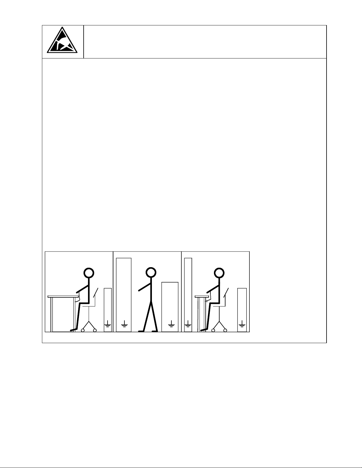
For easy reference, the protective measures necessary when dealing with sensitive electronic components
are illustrated in the sketches below.
a = Conductive flooring d = Anti-static overall
b = Anti-static table e = Anti-static chain
c = Anti-static footwear f = Grounding connections of cabinets
b
a
d
e
f f f
c
d
a
b
f f
c
d
e
a
Seated workstation Standing workstation Standing/seated workstation
Siemens Energy & Automation 1-3
SIMOREG DC Master Base Drive Panel Operating Instructions
Page 9

NOTES:
1-4 Siemens Energy & Automation
SIMOREG DC Master Base Drive Panel Operating Instructions
Page 10

2 Description
2.1 Base Drive Panel Description
Series 6RA70 SIMOREG DC MASTER Base Drive Panels are complete drive assemblies ready to be
installed and operated. They include a 3-phase armature converter, single-phase field converter, main
contactor, protective semiconductor fuses, control power transformer, and power / control terminals.
Base Drive Panels are fully digital, compact units which supply the armature and field of variablespeed DC drives with rated armature currents from 15A to 1680A. The motor field circuit can be
supplied with DC currents of up to 85A (current levels depend on the armature rated current).
2.2 General Information
Series 6RA70 SIMOREG DC MASTER converters are characterized by their compact, space-saving
construction. Their compact design makes them particularly easy to service and maintain since
individual components are readily accessible. The electronics box contains the basic electronic
circuitry as well as any supplementary option boards.
All SIMOREG DC MASTER units are equipped with a PMU simple operator panel mounted in the
converter door. The panel consists of a five-digit, seven-segment display, three LED’s as status
indicators and three parameterization keys. The PMU also features connector X300 with an USS
interface in accordance with the RS232 or RS485 standard. The panel provides all the facilities for
making adjustments or settings and displaying measured values required to start-up the converter.
The OP1S optional converter operator panel can be mounted directly in the converter door or
externally, e.g., in the cubicle door. When mounted remotely, the OP1S can be connected to the
converter with cables up to 5 meters (15 feet) length. Cable up to 50 meter (164 feet) in length can be
used if a separate 5 VDC power supply is available. The OP1S connects to the SIMOREG through
connector X300 using the RS485 interface. The OP1S can be installed as an economic alternative to
conventional door mounted metering devices (i.e., voltmeters, ammeters, and speed indicator).
The OP1S features a liquid crystal display with 4 x 16 characters for displaying parameter names in
plain text. English, German, French, Spanish and Italian can be selected as the display languages. In
addition the OP1S can store parameter sets for easy downloading to other drives.
The converter can also be parameterized on a standard PC with appropriate software connected to the
serial interface on the basic unit. This PC interface is used during start-up, for maintenance during
shutdown and for diagnosis in operation. Furthermore, converter software upgrades can be loaded
through this interface for storage in flash memory.
On single-quadrant converters, a fully controlled three-phase bridge supplies the armature. On fourquadrant converters, two fully controlled three-phase bridges are connected in an inverse-parallel
connection to allow both positive and negative armature current. For the field converter, a singlephase, half-controlled 2-pulse bridge supplies the motor shunt field.
The armature and field converters can operate with AC line frequencies from 45 to 65 Hz. If required
for a specific application, the frequency of the armature and field AC supplies can be different. The
armature converter 3 phase AC supply is phase insensitive however on base drives rated 1180, 1660
and 1680 amperes, the 3 phase cooling fan must be connected to get the proper direction of rotation.
The power section cooling system is monitored by means of temperature sensors.
Siemens Energy & Automation 2-1
SIMOREG DC Master Base Drive Panel Operating Instructions
Page 11

The power section for the armature and field converters is constructed of isolated thyristor modules for
converters rated from 15A to 850A at 460VAC-line voltage. The heat sink in this case is electrically
isolated and at ground potential. On converters rated 1180, 1660 and 1680 amperes at 460 VAC, the
power section for the armature circuit is constructed using disk thyristors and the heat sinks are at line
voltage potential. The housing and terminal covers on power connections provide protection against
accidental contact for operators working in the vicinity. All connecting terminals are accessible from the
front.
All open and closed-loop drive control and communication functions are performed by two powerful
microprocessors. Drive control functions are implemented in the software as program modules that can
be "wired up" and changed by parameters.
2.3 Rated DC Current:
The rating plate of the 6RA70 power module has 2 rated currents listed on it. The first output rating is a
IEC class I ratings and has no bearing on the base drive panel rating. The second rating is the US
(NEMA) rating which the Base Drive Panel rating is derived from.
The US (NEMA) rated current allows operation at this rated current followed by an overload of 150%
for 60 seconds in a 45°C ambient. The overload can be applied no sooner than every 10 minutes.
Base Drive Panels are designed using the US rating which means that fuses, contactors, and terminal
blocks are sized for the rated US (NEMA) current.
The IEC class I rating is the maximum current the power module can supply continuously with no
overload. Because an overload is not possible the class I rated current is higher than the US rating.
The IEC class I rating cannot be used with Base Drive Panels because the Base Drive Panel fuses,
contactors, and terminal blocks will be overloaded.
The microprocessor calculates the current I
thyristors are not damaged in overload operation.
2.4 Card Rack Assembly
One of the many features of the 6RA70 is its ability to expand its functionality modularly through the
use of adding additional option cards inserted in the internal card rack of the power module. A
complete list of the option cards can be found in 6RA70 catalog available from your local Siemens
Sales office.
The card rack assembly contains the CUD1 microprocessor board and two additional slots for two full
size option cards or four half-size option cards. The back plane of the card rack assembly contains an
EEPROM allowing the CUD1 to be replaced without reprogramming of the parameters. Since
additional information specific to the individual unit is programmed into the back plane of the
card rack assembly (model #, serial #, PIN code, etc..) the card rack assembly should never be
interchanged with another unit. If ordering an additional back plane (part # 6RY1703-0GA01)
the model and serial number of the power module will be required.
2
t value of the power section cyclically to ensure that the
2-2 Siemens Energy & Automation
SIMOREG DC Master Base Drive Panel Operating Instructions
Page 12

3 Parts and Service
3.1 Base Drive Panel Catalog Numbers
US RATING
(Amps DC)
1-QUAD TYPE
(Catalog No.)
4-QUAD TYPE
(Catalog No.)
Horsepower
(240V DC 1)
Horsepower
(500V DC)
15 6RA7013-2FS22-0 6RA7013-2FV62-0 3HP 7.5HP
30 6RA7018-2FS22-0 6RA7018-2FV62-0 7.5HP 15HP
60 6RA7025-2FS22-0 6RA7025-2FV62-0 15HP 30HP
100 6RA7030-2FS22-0 6RA7030-2FV62-0 25HP 60HP
140 6RA7072-2FS22-0 6RA7072-2FV62-0 40HP 75HP
210 6RA7075-2FS22-0 6RA7075-2FV62-0 60HP 125HP
255 6RA7077-2FS22-0 6RA7077-2FV62-0 75HP 150HP
430 6RA7082-2FS22-0 6RA7082-2FV62-0 125HP 250HP
510 6RA7083-2FS22-0 6RA7083-2FV62-0 150HP 300HP
850 6RA7087-2FS22-0 6RA7087-2FV62-0 250HP 500HP
1180
(2)
6RA7091-2FS22-0 6RA7091-2FV62-0 350HP 700HP
1660
1680
(2)
(2)
6RA7094-2FS22-0 6RA7094-2FV62-0 500HP 1000HP
6RA7094-2FS22-085 6RA7094-2FV62-085 500HP 1000HP
1) Standard voltage configuration
as shipped is 460V AC.
See Technical application note
for 230V AC connection.
2) Standard voltage configuration
as shipped is 460V AC.
See Technical application note
for 575V AC connection on 1180
1660 & 1680A Base drives
Siemens Energy & Automation 3-1
SIMOREG DC Master Base Drive Panel Operating Instructions
Page 13

3.2 Service
Spare Parts
An excellent stock of drive products spare parts is maintained at the Alpharetta, Georgia factory. Same
day delivery and after hour shipments can be serviced from this stock, including on weekends and
holidays. To contact Customer Service, simply call our Customer Service Group general phone number:
1-800-333-PIC1 (7421)
Technical Assistance
Should you need technical assistance (other than ordering a part), a reliable answering service ensures
that your request is relayed immediately to one of our technical support engineers 24 hours a day. To
contact the Technical Support and Field Service groups simply call:
1-800-333-PIC1 (7421)
3-2 Siemens Energy & Automation
SIMOREG DC Master Base Drive Panel Operating Instructions
Page 14

3.3 Option Part Numbers
Options Order No.
Terminal expansion card (CUD2) 6RX1700-0AK00
User-friendly operator control panel (OP1S) 6SE7090-0XX84-2FK0
AOP1 adapter for mounting OP1A in cubicle door, including
6SX7010-0AA00
5 m connecting cable
PMU-OP1S connecting cable, 3m 6SX7010-0AB03
PMU-OP1S connecting cable, 5m 6SX7010-0AB05
LBA Local bus adapter for the electronics box
6SE7090-0XX84-4HA0
Note: LBA is needed to install any boards listed below
ADB Adapter board
6SE7090-0XX84-0KA0
Note: ADB is always needed to install CBC, CBP2, CBD,
EB1, EB2, SBP and SLB boards
SBP Pulse encoder evaluation board
EB1 Terminal expansion board
EB2 Terminal expansion board
SLB SIMOLINK board
2)
6SX7010-0FJ00
CBP2 Communications board interface for PROFIBUS
CBC Communications board interface for CAN protocol
CBD Communications board interface for DeviceNet protocol
1) 2)
6SX7010-0FA00
2)
6SX7010-0KB00
2)
6SX7010-0KC00
2)
6SX7010-0FF05
2)
6SX7010-0FG00
2)
6SX7010-0FK00
T400 Technology board with SPW 420 Axial winder software 2) 6DD1-842-0AA0
T400 Technology board with SPW 440 Angular Synchr. Software 2) 6DD1-842-0ABO
1) A pulse encoder evaluation circuit is a standard component of the basic SIMOREG converter. The SBP only
needs to be ordered in configurations requiring evaluation of a second pulse encoder.
2) The LBA local bus adapter and ADB adapter board must be ordered as additional components for installing
supplementary boards in the SIMOREG converter.
Siemens Energy & Automation 3-3
SIMOREG DC Master Base Drive Panel Operating Instructions
Page 15

3.4 Spare Parts
Printed Circuit Boards
DESCRIPTION WHERE USED
US Rating 460V
Microprocessor board CUD1
(C98 043-A7001-L1)
Power Interface board 1Q (85 to 575 VAC)
(C98 043-A7002-L1)
Power Interface board 4Q (85 to 575 VAC)
(C98 043-A7002-L4)
PMU Operator Panel (C98 043-A7005-L1) All Ratings 6RY1704-0AA00 -
Field Supply board (C98 043-A7014-L1) 30 to 100 Amp 6RY1703-0CA03 1
Field Supply board (C98 043-A7014-L2) 140 to 510 Amp 6RY1703-0CA01 1
Field Supply board (C98 043-A7004-L1) 850 to 1660 Amp 6RY1703-0EA01 1
Field Supply board (C98 043-A7004-L3) 1680 Amp 6RY1703-0EA03 1
Snubber board (C98 043-A7007-L4) 60 to 100 Amp 6RY1703-0FA04
Snubber board (C98 043-A7007-L6) 30, 140 & 210 Amp 6RY1703-0FA11 -
Snubber board (C98 043-A7011-L6) 255 & 430 Amp 6RY1703-0FA10 -
Snubber boards (C98 043-A7011-L1) 510 & 850 Amp 6RY1703-0FA06 -
All Ratings 6RY1703-0AA00 1
All 1Q Ratings 6RY1703-0DA01 1
All 4Q Ratings 6RY1703-0DA02 1
PART
NUMBER
RECOM
SPARE
Main Power Section Connector board
(C98 043-A7010-L2)
Fuse for Power Supply, 1 amp F1, F2
Mounted on Power Interface board
15 Amp (1Q, 4Q) 6RY1703-0CA04 1
15 – 1680 Amp 6RY1702-0BA00 2
Cables
DESCRIPTION WHERE USED
US Rating 460V
Ribbon Cable 20 pole X102 15 amp 6RY1707-0AA00
Ribbon Cable 64 pole X101 15 to 430 amp 6RY1707-0AA01
Ribbon Cable 20 pole X102 30 to 210 amp 6RY1707-0AA02 -
Ribbon Cable 20 pole X102 255 & 430 amp 6RY1707-0AA03 -
Ribbon Cable 20 pole X102 510 amp 6RY1707-0AA12 -
Ribbon Cable 64 pole X101 510 amp 6RY1707-0AA05 -
Ribbon Cable 20 pole X102 850 to 1680 amp 6RY1707-0AA06 -
Ribbon Cable 64 pole X101 850 to 1680 amp 6RY1707-0AA07 -
PART
NUMBER
RECOM
SPARE
-
3-4 Siemens Energy & Automation
SIMOREG DC Master Base Drive Panel Operating Instructions
Page 16

Fans/Blowers
DESCRIPTION WHERE USED
US Rating 460V
PART NUMBER RECOM
SPARE
FAN, 24 VDC
(C98130-A1256-C553)
FAN, 230 VAC, 1 Phase
(C98130-A7004-B130)
FAN, 230 VAC, 1 Phase
(C98130-A7004-B330)
FAN, 460 VAC, 3 Phase
(C98 247-S1002-C25)
140 & 210 amp 6RY1701-0AA07 2
255, 430 & 510
amp
850 amp 6RY1701-0AA12 1
1180, 1660
&1680 amp
6RY1701-0AA11 1
6RY1701-0AA04 1
Thyristors & Diodes
Armature Converter Thyristor Modules, (for 1-Quad Drives)
DESCRIPTION WHERE USED
US Rating 460V
Dual Thyristor Module 15 amp 1Q 6RY1700-0AA16 3
Dual Thyristor Module 30 amp 1Q 6RY1700-0AA17 3
Dual Thyristor Module 60 amp 1Q 6RY1700-0AA18 3
PART NUMBER RECOM
SPARE
Dual Thyristor Module 100 amp 1Q 6RY1700-0AA11 3
Dual Thyristor Module 140 amp 1Q 6RY1700-0AA14 3
Dual Thyristor Module 210 amp 1Q 6SY7010-0AA02 3
Dual Thyristor Module 255 amp 1Q 6RY1700-0AA15 3
Dual Thyristor Module 430 amp 1Q 6SY7010-0AA05 3
Dual Thyristor Module 510 amp 1Q 6SY7010-0AA04 3
Dual Thyristor Module 850 amp 1Q 6RY1700-0AA04 3
Thyristor/Heatsink Assembly, Front
(C98 130-A1255-B510)
Thyristor/Heatsink Assembly, Back
(C98 130-A1255-B511)
Thyristor/Heatsink Assembly, Front
(C98 130-A1255-B520)
Thyristor/Heatsink Assembly, Back
(C98 130-A1255-B521)
Thyristor/Heatsink Assembly, Front 1680 amp 1Q 6RY1702-0CA30 2
Thyristor/Heatsink Assembly, Back 1680 amp 1Q 6RY1702-0CA31 2
1180 amp 1Q 6RY1702-0CA15 2
1180 amp 1Q 6RY1702-0CA16 2
1660 amp 1Q 6RY1702-0CA17 2
1660 amp 1Q 6RY1702-0CA18 2
Siemens Energy & Automation 3-5
SIMOREG DC Master Base Drive Panel Operating Instructions
Page 17

Armature Converter Thyristor Modules, (for 4-Quad Drives)
DESCRIPTION WHERE USED
US Rating 460V
Dual Thyristor Module 15 amp 4Q 6RY1700-0AA16 3
Dual Thyristor Module 30 amp 4Q 6RY1700-0AA17 3
Dual Thyristor Module 60 & 100 amp 4Q 6RY1700-0AA11 3
Dual Thyristor Module 140 amp 4Q 6RY1700-0AA14 3
Dual Thyristor Module 210 amp 4Q 6SY7010-0AA02 3
Dual Thyristor Module 255 amp 4Q 6RY1700-0AA15 3
Dual Thyristor Module 430 amp 4Q 6SY7010-0AA05 3
Dual Thyristor Module 510 to 850 amp 4Q 6SY7010-0AA04 3
Thyristor/Heatsink Assembly
C98 130-A1256-B510
Thyristor/Heatsink Assembly
C98 130-A1256-B520
Thyristor/Heatsink Assembly 1680 amp 4Q 6RY1702-0CA34 2
1180 amp 4Q 6RY1702-0CA02 2
1660 amp 4Q 6RY1702-0CA03 2
PART NUMBER RECOM
SPARE
Field Converter Thyristor Modules
DESCRIPTION WHERE USED
US Rating 460V
Dual Thyristor Module 15 to 430 amp 6RY1700-0AA12 1
Dual Thyristor Module 510 to 1660 amp 6RY1700-0AA17 1
Dual Thyristor Module 1680 amp 6RY1700-0AA05 1
PART NUMBER RECOM
Field Converter Diode Modules
DESCRIPTION WHERE USED
US Rating 460V
Dual Diode Module 15 to 430 amp 6RY1700-0BA04 1
Dual Diode Module 510 to 1660 amp 6RY1700-0BA01 1
Dual Diode Module 1680 AMP 6RY1700-0BA05 1
PART NUMBER RECOM
SPARE
SPARE
3-6 Siemens Energy & Automation
SIMOREG DC Master Base Drive Panel Operating Instructions
Page 18

Power Fuses
Armature Converter AC Line Fuses, (1PFU - 3 PFU)
DESCRIPTION WHERE USED
US Rating 460V
25 amp, 700 volt 15 amp A1-FUF-END-C25 3
50 amp, 700 volt 30 amp A1-FUF-END-CDN 3
70 amp, 500 volt 60 amp A1-FUF-00D-014 3
125 amp, 500 volt 100 amp A1-FUF-00D-018 3
150 amp, 500 volt 140 amp A1-FUF-00D-019 3
200 amp, 500 volt 210 amp A1-FUF-00D-021 3
250 amp, 500 volt 255 amp A1-FUF-00D-023 3
400 amp, 500 volt 430 amp A1-FUF-00D-028 3
500 amp, 500 volt 510 amp A1-FUF-00D-030 3
800 amp, 800 volt (Leg Fuse) 850 amp 3NE3338-8 3
1000 amp, 660 volt (Leg Fuse) 1180 amp 6RY1702-0BA02 3
1250 amp, 660 volt (Leg Fuse) 1660 amp 6RY1702-0BA01 3
1500 amp, 660 volt (Leg Fuse) 1680 amp 6RY1702-0BA05 3
PART NUMBER RECOM
SPARE
Armature Converter DC Fuses, 4-Quad Only, (4PFU)
DESCRIPTION WHERE USED
US Rating 460V
25 amp, 700 volt 15 amp A1-FUF-END-C25 2
50 amp, 700 volt 30 amp A1-FUF-END-CDN 2
90 amp, 700 volt 60 amp A1-FUF-00E-016 2
150 amp, 700 volt 100 amp A1-FUF-00E-019 2
175 amp, 700 volt 140 amp A1-FUF-00E-020 2
250 amp, 700 volt 210 amp A1-FUF-00E-023 2
300 amp, 700 volt 255 amp A1-FUF-00E-025 2
500 amp, 700 volt 430 amp A1-FUF-00E-030 2
600 amp, 700 volt 510 amp A1-FUF-00E-031 2
PART NUMBER RECOM
SPARE
Siemens Energy & Automation 3-7
SIMOREG DC Master Base Drive Panel Operating Instructions
Page 19

Field Converter AC Line Fuses (1 & 2FSFU)
DESCRIPTION WHERE USED
US Rating 460V
20 amp, 700 volt 60 to 210 amp A1-FUF-END-C20 2
40 amp, 700 volt 255 to 850 amp A1-FUF-END-C40 2
50 amp, 700 volt 1180 to 1660 amp A1-FUF-END-C50 2
125 amp, 600 volt 1680 amp A1-FUF-HHA-024 2
PART NUMBER RECOM
Control Transformer Primary Fuses (1CFU, 2CFU)
DESCRIPTION WHERE USED
US Rating 460V
1.25 amp, 600 volt, Class "CC" 15 to 100 amp A1-FUF-AFA-006 2
2.5 amp, 600 volt, Class "CC" 140 & 210 amp
1180, 1660 &
1680 amp
3.5 amp, 600 volt, Class "CC" 255 to 510 amp
850 amp, (460
volt input only)
PART NUMBER RECOM
A1-FUF-AFA-011 2
A1-FUF-AFA-014 2
SPARE
SPARE
5 amp, 600 volt, Class "CC" 1180, 1660 &
1680 amp
4CFU, 5CFU,
(
6CFU, 7CFU)
A1-FUF-AFA-016 4
Control Transformer Secondary Fuse (3CFU)
DESCRIPTION WHERE USED
US Rating 460V
0.75 amp, 250 volt, Type MDL 15 to 100 amp A1-FUF-DKA-GBF 2
1.5 amp, 250 volt, Type MDL 140 & 210 amp
1180,1660 &
1680 amp
2 amp, 250 volt, Type MDL 255 to 510 amp A1-FUF-DKA-GBV 2
6.25 amp, 250 volt, Type MDL 850 amp A1-FUF-DKA-GCM 2
PART NUMBER RECOM
A1-FUF-DKA-GBP 2
SPARE
3-8 Siemens Energy & Automation
SIMOREG DC Master Base Drive Panel Operating Instructions
Page 20

Control Transformer (1CTR, 2CTR, 3CTR)
DESCRIPTION
460 VAC Primary
115 VA, 230 VAC secondary 15 to 100 amp A1-TRC-Q0C-285 -
250 VA, 230 VAC secondary 140 & 210 amp
350 VA, 230 VAC secondary 255 to 510 amp A1-TRC-Q0C-287 -
1000 VA, 230 VAC secondary 850 amp A1-TRC-Q0C-288 -
750 VA, 460 VAC secondary 1180,1660 &
WHERE USED
US Rating 460V
1180, 1660 &
1680 amp
1680 amp
PART NUMBER RECOM
A1-TRC-Q0C-286 -
A1-TRC-Q0C-289 -
Main Contactor (M)
DESCRIPTION WHERE USED
US Rating 460V
3 Pole AC contactor, 240 VAC coil 15 amp 3RT1016-1AP61 -
3 Pole AC contactor, 240 VAC coil 30 amp 3RT1025-1AP60 -
3 Pole AC contactor, 240 VAC coil 60 amp 3RT1035-1AP60 -
PART NUMBER RECOM
SPARE
SPARE
3 Pole AC contactor, 240 VAC coil 100 amp 3RT1044-1AP60 -
3 Pole AC contactor, 240 VAC coil 140 amp 3RT1045-1AP60 -
3 Pole AC contactor, 240 VAC coil 210 amp 3RT1456-6AP36 -
3 Pole AC contactor, 240 VAC coil 255 amp 3RT1456-6AP36 -
1 Pole DC contactor, 250 VDC coil 430 to 1680 amp A1-CRD-CAC-010 -
Contactor Coil Suppressor (1SP, ENSP)
DESCRIPTION WHERE USED
US Rating 460V
Suppressor, varistor type 127 – 240 V 15 amp
430 to 1680 amp
Suppressor, varistor type 127 – 240 V 30 to 140 amp 3RT1926-1BD00 -
PART NUMBER RECOM
3RT1916-1BD00 -
Auxiliary Relay, (EN), and Rectifier Bridge, (MREC)
DESCRIPTION WHERE USED
US Rating 460V
PART NUMBER RECOM
SPARE
SPARE
Relay, 2-NO, 2-NC, 230 VAC coil 430 to 1680 amp 3RH1122-1AP60 -
Rectifier Bridge, 1 Phase, 5A, 800 V 430 to 1680 amp A1-116-002-001 -
Siemens Energy & Automation 3-9
SIMOREG DC Master Base Drive Panel Operating Instructions
Page 21

3.5 Standard Terms and Conditions of Sale
Siemens Energy & Automation, Inc. ("Seller")
1. WARRANTY - Seller warrants that on the date of shipment the goods are of the kind and quality described herein and are free of non-
conformities in workmanship and material. This warranty does not apply to goods delivered by Seller but manufactured by others.
(b) Buyer's exclusive remedy for a nonconformity in any item of the goods shall be the repair or the replacement (at Seller's option) of
the item and any affected part of the goods. Seller's obligation to repair or replace shall be in effect for a period of one (1) year from
initial operation of the goods but not more than eighteen (18) months from Seller's shipment of the goods, provided Buyer has sent
written notice within that period of time to Seller that the goods do not conform to the above warranty. Repaired and replacement parts
shall be warranted for the remainder of the original period of notification set forth above, but in no event less than 12 months from repair
or replacement. At its expense, Buyer shall remove and ship to Seller any such nonconforming items and shall reinstall the repaired or
replaced parts. Buyer shall grant Seller access to the goods at all reasonable times in order for Seller to determine any nonconformity in
the goods. Seller shall have the right of disposal of items replaced by it. If Seller is unable or unwilling to repair or replace, or if repair or
replacement does not remedy the nonconformity, Seller and Buyer shall negotiate an equitable adjustment in the contract price, which
may include a full refund of the contract price for the nonconforming goods.
(c) SELLER HEREBY DISCLAIMS ALL OTHER WARRANTIES, EXPRESS OR IMPLIED, EXCEPT THAT OF TITLE. SPECIFICALLY,
IT DISCLAIMS THE IMPLIED WARRANTIES OF MERCHANTABILITY, FITNESS FOR A PARTICULAR PURPOSE, COURSE OF
DEALING AND USAGE OF TRADE.
(d) Buyer and successors of Buyer are limited to the remedies specified in this article and shall have no others for a nonconformity in
the goods. Buyer agrees that these remedies provide Buyer and its successors with a minimum adequate remedy and are their
exclusive remedies, whether Buyer's or its successors' remedies are based on contract, warranty, tort (including negligence), strict
liability, indemnity, or any other legal theory, and whether arising out of warranties, representations, instructions, installations, or nonconformities from any cause.
Note: This article 1 does not apply to any software which may be furnished by Company. In such cases, the attached Software License
Addendum applies.
2. PATENTS - Seller shall pay costs and damages finally awarded in any suit against Buyer or its vendees to the extent based upon a
finding that the design or construction of the goods as furnished infringes a United States patent (except infringement occurring as a
result of incorporating a design or modification at Buyer's request), provided that Buyer promptly notifies Seller of any charge of
infringement, and Seller is given the right at its expense to settle such charge and to defend or control the defense of any suit based
upon such charge. Seller shall have no obligation hereunder with respect to claims, suits or proceedings, resulting from or related to, in
whole or in part, (i) the use of software or software documentation, (ii) compliance with Buyer's specifications, (iii) the combination with,
or modification of, the goods after delivery by Seller, or (iv) the use of the goods, or any part thereof, in the practice of a process. THIS
ARTICLE SETS FORTH SELLER'S ENTIRE LIABILITY WITH RESPECT TO PATENTS.
3. PERFORMANCE; DELAYS - TTimely performance by Seller is contingent upon Buyer's supplying to Seller, when needed, all
required technical information and data, including drawing approvals, and all required commercial documentation. If Seller suffers delay
in performance due to any cause beyond its reasonable control, the time of performance shall be extended a period of time equal to the
period of the delay and its consequences. Seller will give to Buyer notice within a reasonable time after Seller becomes aware of any
such delay.
4. SHIPMENT, TITLE AND RISK OF LOSS - (a) The term "shipment" means delivery to the initial carrier in accordance with the delivery
terms of this contract. Seller may make partial shipments. Seller shall select method of transportation and route, unless terms are f.o.b
point of shipment and Buyer specifies the method and route and is to pay the freight costs in addition to the price. When terms are f.o.b.
destination or freight allowed to destination, "destination" means common carrier delivery point (within the United States, excluding
Alaska and Hawaii) nearest the destination.
(b) Title to the goods and risk of loss or damage shall pass to Buyer at the f.o.b. point. Seller shall not be responsible for damage to the
goods after having received "in good order" receipts from the carrier.
5. TAXES - Any applicable duties or sales, use, excise, value-added or similar taxes will be added to the price and invoiced separately
(unless an acceptable exemption certificate is furnished).
6. TERMS OF PAYMENT - (a) Unless otherwise stated, all payments shall be in United States dollars, and a pro rata payment shall
become due as each shipment is made. If shipment is delayed by Buyer, date of notice of readiness for shipment shall be deemed to be
date of shipment for payment purposes.
(b) On late payments, the contract price shall, without prejudice to Seller's right to immediate payment, be increased by 1 1/2% per
month on the unpaid balance, but not to exceed the maximum permitted by law.
(c) If any time in Seller's judgment Buyer is unable or unwilling to meet the terms specified, Seller may require satisfactory assurance or
full or partial payment as a condition to commencing or continuing manufacture or making shipment, and may, if shipment has been
made, recover the goods from the carrier, pending receipt of such assurances.
3-10 Siemens Energy & Automation
SIMOREG DC Master Base Drive Panel Operating Instructions
Page 22

7. NONCANCELLATION - Buyer may not cancel or terminate for convenience, or direct suspension of manufacture, except with Seller's
written consent and then only upon terms that will compensate Seller for its engineering, fabrication and purchasing charges and any other
costs relating to such cancellation, termination or uspension, plus a reasonable amount for profit.
8. NUCLEAR - Buyer represents and warrants that the goods covered by this contract shall not be used in or in connection with a nuclear
facility or application. If Buyer is unable to make such representation and warranty, then Buyer agrees to indemnify and hold harmless Seller
and to waive and require its insurers to waive all right of recovery against Seller for any damage, loss, destruction, injury or death resulting
from a "nuclear incident", as that term is defined in the Atomic Energy Act of 1954, as amended, whether or not due to Seller's negligence.
9. LIMITATION OF LIABILITY - Neither Seller, nor its suppliers shall be liable, whether in contract, warranty, failure of a remedy to achieve
its intended or essential purposes, tort (including negligence), strict liability, indemnity or any other legal theory, for loss of use, revenue or
profit, or for costs of capital or of substitute use or performance, or for indirect, special, liquidated, incidental or consequential damages, or for
any other loss or cost of a similar type, or for claims by Buyer for damages of Buyer's customers. Seller's maximum liability under this
contract shall be the contract price. Buyer and Seller agree that the exclusions and limitations set forth in this article are separate and
independent from any remedies which Buyer may have hereunder and shall be given full force and effect whether or not any or all such
remedies shall be deemed to have failed of their essential purpose.
10. GOVERNING LAW AND ASSIGNMENT - The laws of the State of Georgia shall govern the validity, interpretation and enforcement of
this contract, without regard to its conflicts of law principles. The application of the United Nations Convention on Contracts for the
International Sale of Goods shall be excluded. Assignment may be made only with written consent of both parties; provided, however, Seller
may assign to its affiliate without Buyer's consent.
11. ATTORNEY FEES - Buyer shall be liable to Seller for any attorney fees and costs incurred by Seller in enforcing any of its rights
hereunder.
12. DISPUTES - Either party may give the other party written notice of any dispute arising out of or relating to this contract and not resolved
in the normal course of business. The parties shall attempt in good faith to resolve such dispute promptly by negotiations between executives
who have authority to settle the dispute. If the matter has not been resolved within 60 days of the notice, either party may initiate non-binding
mediation of the dispute.
13. STATUTE OF LIMITATIONS - To the extent permitted by applicable law, any lawsuit for breach of contract, including breach of warranty,
arising out of the transactions covered by this contract, must be commenced not later than twelve (12) months from the date the cause of
action accrued.
14. PRICES - In the event of a price increase or decrease, the price of goods on order will be adjusted to reflect such increase or decrease.
This does not apply to a shipment held by request of Buyer. Goods already shipped are not subject to price increase or decrease. Orders on
a bid or contract basis are not subject to this article. Orders amounting to less than $100.00 net will be invoiced at $100.00 plus
transportation charges for goods covered by discount schedules. Seller's prices include the costs of standard domestic packing
deviation from this standard packing (domestic or export), including U.S. Government sealed packing, will result in extra charges. To
determine such extra charges, consult Seller's sales offices.
15. ADDITIONAL TERMS OF PAYMENT - (a) Invoice payment terms are as shown on latest discount sheets as issued from time to time.
Cash discounts are not applicable to notes or trade acceptances, to prepaid transportation charges when added to Seller's invoices or to
discountable items if there are undisputed past due items on the account. Portions of an invoice in dispute should be deducted and the
balance remitted with a detailed explanation of the deduction. Cash discounts will only be allowed on that portion of the invoice paid within
the normal discount period.
(b) Freight will be allowed to any common-carrier free-delivery point within the United States, excluding Alaska and Hawaii, on shipments
exceeding $1,000 net or more providing Seller selects the carrier. On shipments to Alaska and Hawaii, freight will be allowed to dockside at
the listed port of debarkation nearest the destination point on shipments of $1,000 net or more. Buyer shall pay all special costs such as
cartage, stevedoring and insurance. Special freight allowances are as shown on latest discount sheets as issued from time to time.
Cataloged weights are estimated, not guaranteed. Seller assumes no responsibility for tariff classifications on carriers.
16. CHANGES IN LAWS AND REGULATIONS - Seller's prices and timely performance are based on all applicable laws, rules, regulations,
orders, codes, standards or requirements of governmental authorities effective on the date of Seller's proposal. Any change to any law, rule,
regulation, order, code, standard or requirement which requires any change hereunder shall entitle Seller to an equitable adjustment in the
prices and any time of performance.
only. Any
Siemens Energy & Automation 3-11
SIMOREG DC Master Base Drive Panel Operating Instructions
Page 23

NOTES:
3-12 Siemens Energy & Automation
SIMOREG DC Master Base Drive Panel Operating Instructions
Page 24
4 Receiving, unpacking
SIMOREG Base Drive Panels are packed at the manufacturing plant in protective containers suitable
for shipping. Avoid dropping and shocks during unloading and moving the SIMOREG during receiving.
Observe the instructions on the package for transport, storage, and correct handling.
If you discover that the Base Drive Panel has been damaged during shipment, please inform your
shipping agent immediately.
WARNING
If a SIMOREG Base Drive Panel was damaged during transport, it must not be connected up
without first being repaired and tested by a qualified repair person.
Non-observance of the safety instructions can result in death, severe personal injury or
substantial property damage.
Only qualified personnel should work on or around the equipment after first becoming
thoroughly familiar with all warning and safety notices and maintenance procedures contained
herein. The successful and safe operation of this equipment is dependent on proper handling,
installation, operation and maintenance.
Procedure for Shipping Damage
SIMOREG Base Drive Panels are normally shipped FOB factory making it the buyers responsibility to
make sure the equipment is received undamaged. Carefully examine the equipment before accepting
the shipment from the transport carrier. If you do not notify the carrier immediately of any damage you
may lose your right to file a damage claim. If required you can request support from the local Siemens
office.
• When received, examine the shipment to ensure that it is complete and not damaged.
• Damaged or missing items that are obviously visible should be specified in the shipping papers
and must be countersigned by personnel from the transport company.
• Immediately notify the transport company in writing of any damage or missing items
Siemens Energy & Automation 4-1
SIMOREG DC Master Base Drive Panel Operating Instructions
Page 25

NOTES:
4-2 Siemens Energy & Automation
SIMOREG DC Master Base Drive Panel Operating Instructions
Page 26
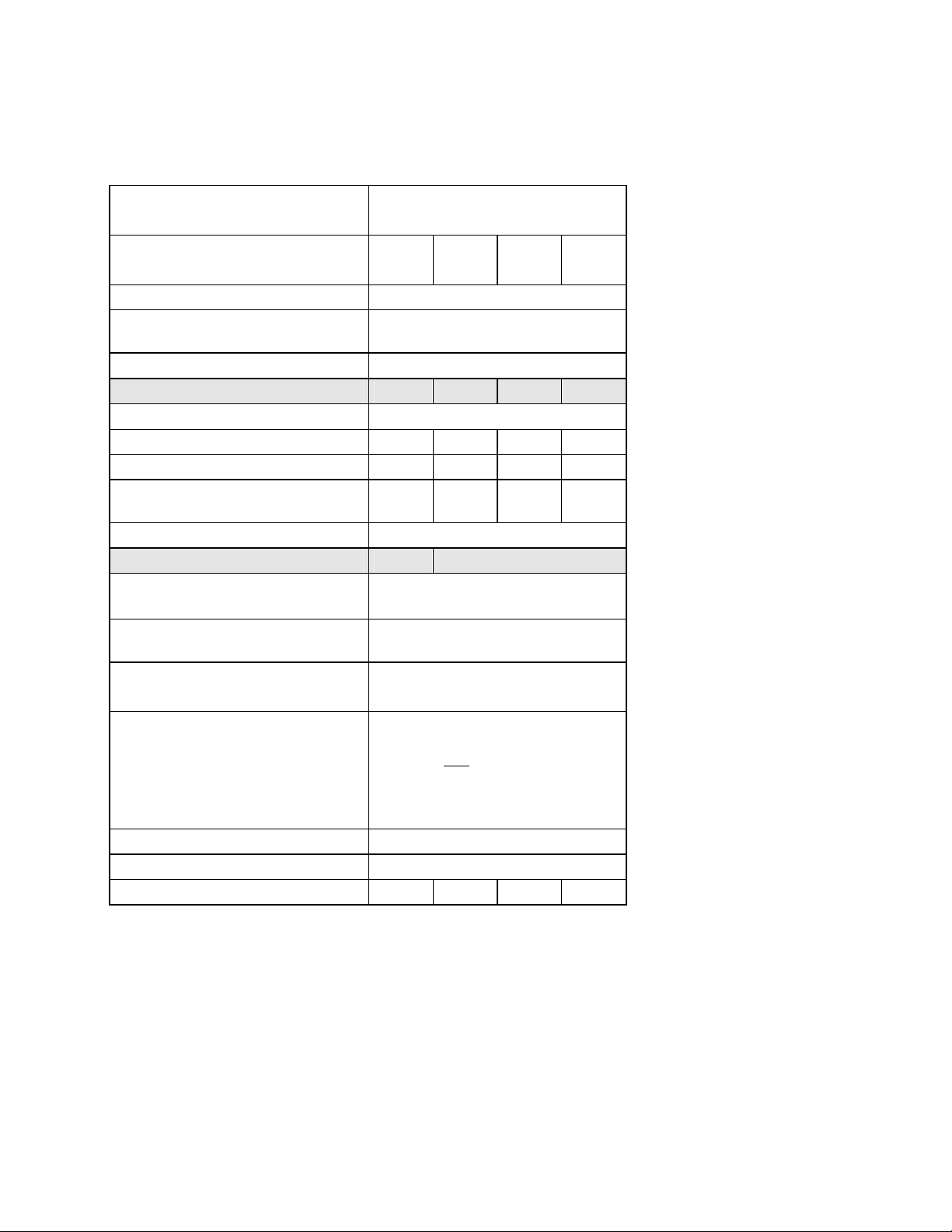
5 Technical data:
5.1 15ADC to 100ADC Base Drive Panels, 3AC 460V, 1 & 4Q
Rated supply voltage
1)
armature
Rated input current
2)
armature + field
V 3 Phase
460 (+10% / – 5%)
A 17.3 34.6 59.2 92
Rated supply voltage field V 1 Phase 460 (+10%)
Rated frequency Hz
45 to 65 Hz self adapting (armature
and field are independent)
Rated DC voltage 3)
Rated DC armature current A
Overload capability 60s 7)
V 500
15 30 60 100
150% of rated DC current
Rated output @ 500 VDC Hp 7 ½ 15 30 60
Rated output @ 240 VDC Hp 3 7 ½ 15 25
Power loss at rated DC current
W 150 200 360 510
(approximate)
Rated DC voltage field V 300
Rated DC field current A
Operational ambient
°C 0 to 45 at I
temperature
Storage and transport
°C – 25 to +70
5 10
rated
self-cooled
4)
temperature
Installation altitude above sea
≤ 1000 m at rated DC current
level
Control stability
∆n = 0.006% of the rated motor
speed, valid for pulse encoder
operation and
digital setpoint
∆n = 0.1% of the rated motor
speed, valid for analog tachometer
6)
or analog setpoint
Degree of protection Open Chassis (IP00)
Dimensions
See dimension drawings in Section 6
Weights (approx.) Lbs. 35 55 60 70
x)
Explanation at end of list of tables
5)
Siemens Energy & Automation 5-1
SIMOREG DC Master Base Drive Panel Operating Instructions
Page 27
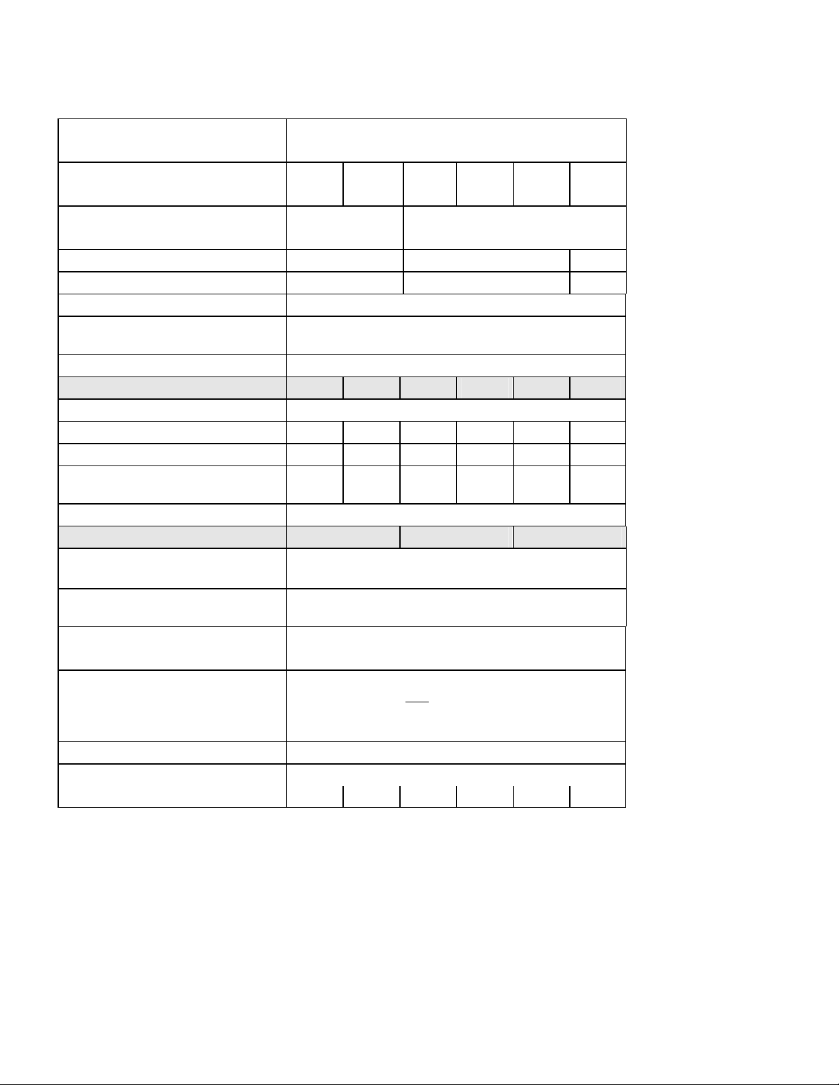
5.2 140ADC to 850ADC Base Drive Panels, 3AC 460V, 1 & 4Q
Rated supply voltage
1)
armature
Rated input current
2)
armature + field
V 3 Phase
460 (+10% / – 5%)
A 129.8 187.2 234.1 377.6 448.2 727
Fan type V Internal 24VDC 1 Phase
230V
Air flow rate
ft
3
/min
100 570 1300
Fan noise level dBA 40 76 85
Rated supply voltage field V 1 Phase 460 (+10%)
Rated frequency Hz
45 to 65 Hz self adapting (armature and field are
independent)
Rated DC voltage 3)
Rated DC armature current A
Overload capability 60s 7)
V 500
140 210 255 430 510 850
150% of rated DC current
Rated output @ 500 VDC Hp 75 125 150 250 300 500
Rated output @ 240 VDC Hp 40 60 75 125 150 250
Power loss at rated DC current
W 740 1000 1300 1915 2180 3850
(approximately)
Rated DC voltage field V 300
Rated DC field current A
Operational ambient
°C 0 to 45 at I
temperature
Storage and transport
°C – 25 to +70
15 25 30
rated
4)
fan-cooled
temperature
Installation altitude above sea
≤ 1000 m at rated DC current
5)
level
Control stability
∆n = 0.006% of the rated motor speed, valid for pulse
encoder operation and
digital setpoint
∆n = 0.1% of the rated motor speed, valid for analog
6)
tachometer or analog setpoint
Degree of protection Open Chassis (IP00)
Dimensions Refer to dimension drawings in Section 6
Weights (approx.) Lbs. 90 95 145 160 210 400
5-2 Siemens Energy & Automation
SIMOREG DC Master Base Drive Panel Operating Instructions
Page 28
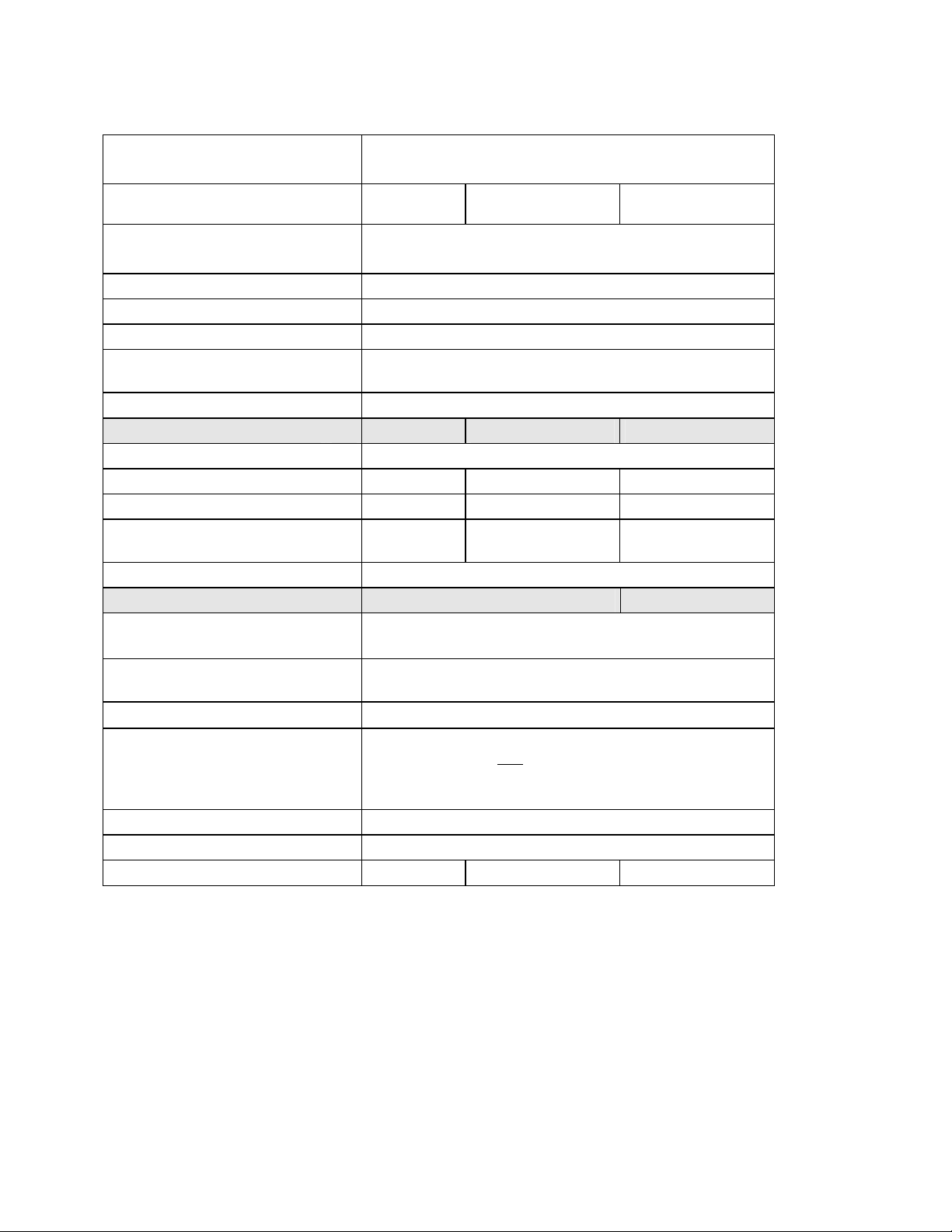
5.3 1180ADC, 1660ADC & 1680ADC Base Drive Panels, 3AC 460V, 1 & 4Q
Rated supply voltage armature
1)
Rated input current armature
2)
V 3 Phase
460 (+10% / – 5%)
A 1000 1401 1455
Fan type V 3 Phase
460V
Air flow rate
ft
3
/min
824
Fan noise level dBA 88
Rated supply voltage field V 1 Phase 460 (+10%)
Rated frequency Hz
45 to 65 Hz self adapting (armature and field are
independent)
Rated DC voltage 2)
Rated DC armature current A
Overload capability 60s 7)
V 500
1180 1660 1680
150% of rated DC current
Rated output @ 500 VDC Hp 700 1000 1000
Rated output @ 240 VDC Hp 350 500 500
Power loss at rated DC current
W 5540 7590 7280
(approximately)
Rated DC voltage field V 300
Rated DC field current A
Operational ambient
°C 0 to 45 at I
temperature
Storage and transport
°C – 25 to +70
40 85
rated
4)
fan-cooled
temperature
Installation altitude above sea level
Control stability
≤ 1000 m at rated DC current
∆n = 0.006% of the rated motor speed, valid for pulse
encoder operation and
digital setpoint
5)
∆n = 0.1% of the rated motor speed, valid for analog
6)
tachometer or analog setpoint
Degree of protection Open Chassis (IP00)
Dimensions Refer to dimension drawings in Section 6
Weights (approx.) Lbs. 725 755 760
Siemens Energy & Automation 5-3
SIMOREG DC Master Base Drive Panel Operating Instructions
Page 29
Notes:
1) Operation with reduced input voltage will result in reduced maximum output voltage accordingly.
2) Values apply for rated DC output current on both the armature and field circuits.
3) The specified output DC voltage can be guaranteed up to an undervoltage of 5% of rated line voltage.
4) The table below gives load values, (DC current), as a function of ambient temperature surrounding the
Base Drive Panel, (refer to P077). Note, Important: When Base Drive Panels are installed into
enclosures, make sure the temperature inside does not exceed 45
rating per the table below.
Ambient temperature % reduction in base drive dc ampere rating
Self-cooled converters Fan-cooled converters
(15, 30, 60, 100 ADC) (140 - 1660 ADC)
+40ºC
+45ºC
+50ºC
+55ºC
+60ºC
– 0 %
– 0 %
– 6 %
– 11 %
– 18 %
– 0 %
– 0 %
– 5 % a)
– 5 % a)
– 5 % a)
a) Operation of fan cooled units at ambients above 50oC is not permitted
because of limitations on the allowable fan operating temperature.
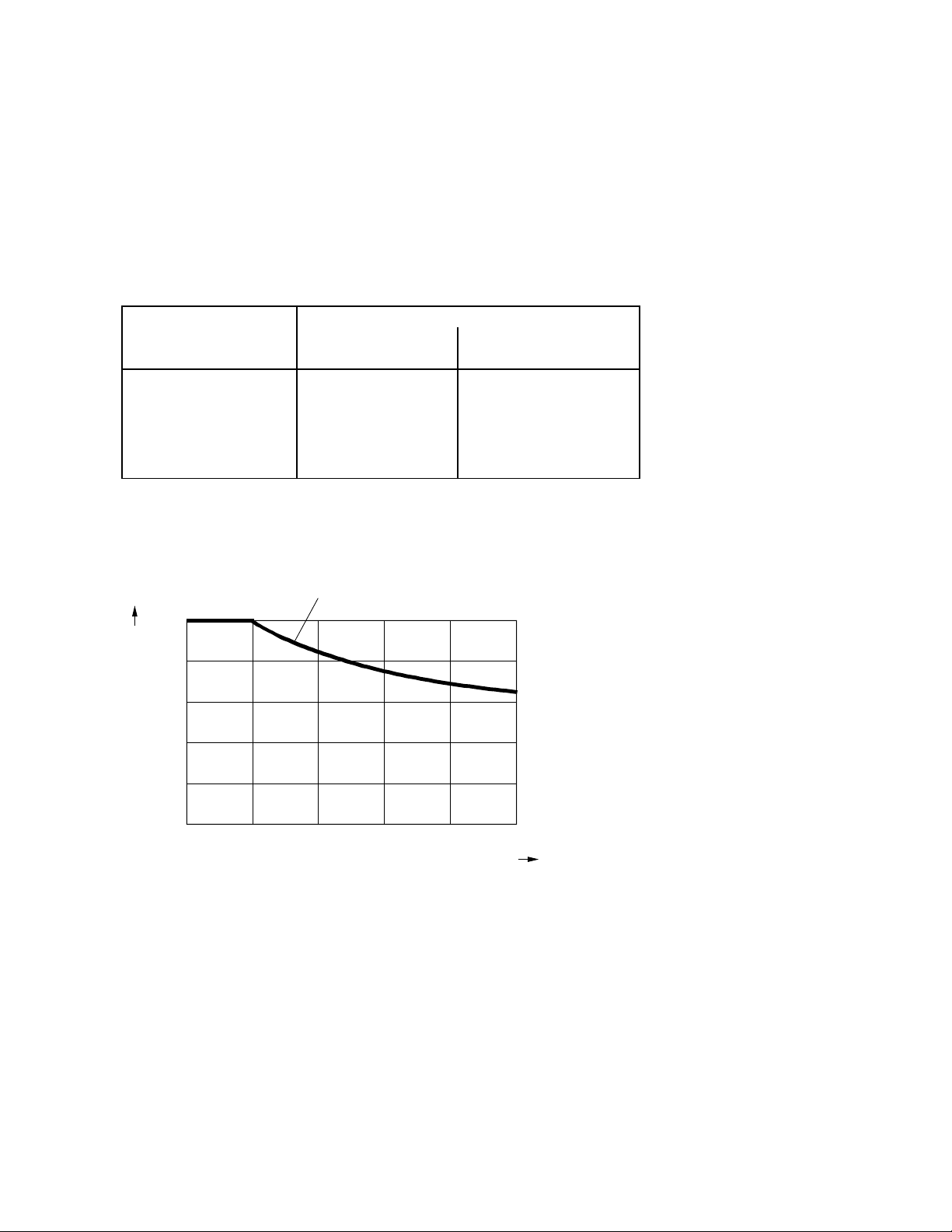
5) Load values, (DC current), as a function of installation altitude (refer to P077)
b1
Percentage
load "b"
%
100
80
o
C, otherwise derate the DC current
60
40
20
0
1000 2000 3000 4000 5000 m
Installation altitude
67%
Curve b1: Reduction factor of load values, (DC current),
at installation altitudes above 1000 m.
No derating of the supply voltages to any circuits is required
up to an installation altitude of 5000 m for basic insulation.
5-4 Siemens Energy & Automation
SIMOREG DC Master Base Drive Panel Operating Instructions
Page 30

6) Requirements to achieve control stability:
The control stability (closed-loop PI control) is referred to the rated motor speed and applies
when the SIMOREG converter is warm. The following conditions are applicable:
• Temperature changes of ±10 °C.
• Line voltage changes corresponding to +10% /
• Temperature coefficient of temperature-compensated tachometer 0.15‰ per 10 °K,
(applies only to analog tachometer).
• Constant setpoint (14-bit resolution).
• Motor, load, and encoder are correctly aligned and the load is balanced.
7) Details of overload capability:
Following operation at rated load, base drive panels are capable of carrying 150% of rated load
for 1 minute, followed by a period of light load operation of such duration that the rms load does
not exceed rated continuous current. Base Drive Panels are designed for operation with
heatsink air inlet temperatures up to 45°C.
5.4 Applicable standards
UL508A
– 5% of the rated input voltage.
National Electrical Code 1999
Siemens Energy & Automation 5-5
SIMOREG DC Master Base Drive Panel Operating Instructions
Page 31

NOTES:
5-6 Siemens Energy & Automation
SIMOREG DC Master Base Drive Panel Operating Instructions
Page 32

6 Installation and Dimensions
6.1 Installation Information
SIMOREG Base Drive Panels are designed as chassis units intended to be mounted inside a protective
enclosure or inside a control room. The units are to be mounted vertically in cubicles usually with the power
connections at the top and the control connections at the bottom. A minimum 100-mm (4-inch) clearance must
be kept above and below the converter in order to ensure unrestricted cooling airflow. The minimum
enclosure size to be used is 23.6 by 23.6 by 86.6 inch high. The open chassis units are designed to operate in
a 45°C ambient. When enclosed in a cubicle the ambient temperature outside the cubicle should not exceed
40°C, which then allows for a 5°C-temperature rise inside the cubicle. Care must be taken in the selection of
the cubicle so that the internal temperature rise does not exceed 5°C. Refer to section 5 for approximate
power loss data.
Note, Important: This equipment is designed and package-protected to handle the normal shock and
vibration typically encountered in shipment. Do not install these Base Drive Panels on equipment subject
to shock or vibration. Select a reasonably clean location for installation, free from corrosive or
conductive materials or fumes.
CAUTION
Failure to lift the Base Drive Panel in the correct manner can result in bodily injury and/or
property damage.
The Base Drive Panel must be lifted using suitable equipment and under the instruction of
appropriately qualified personnel.
The user is responsible for installing the Base Drive Panel, motor, transformer as well as other
equipment according to safety regulations (e.g. NEC), as well as all other relevant national or
local regulations regarding cable sizing and protection, grounding, disconnects, overcurrent
protection, etc.
The Base Drive Panels must be installed in accordance with the relevant safety regulations
(e.g. NEC), as well as all other relevant national and local regulations. It must be ensured that
the grounding, cable sizing and appropriate short-circuit protection have been implemented to
guarantee operational safety and reliability.
Note, Important: Base Drive Panels have high-speed semiconductor fuses installed for
protection of the thyristors in the event high fault currents are encountered. These fuses are
“special purpose” fuses, and do not meet the requirements of the NEC for short-circuit
protection in motor branch circuits. It is necessary to provide other devices for short-circuit
protection. Typically molded case circuit breakers or NEC style fuses are used for this purpose.
Refer to applicable sections of the NEC for additional information.
NOTE
The fundamental principles of EMC in Section 6.1 of SIMOREG 6RA70 DC Master operating
instructions (Order # 6RX1700-0AD76) must be adhered to when installing any unit.
Siemens Energy & Automation 6-1
SIMOREG DC Master Base Drive Panel Operating Instructions
Page 33

6.2 Base Drive Panel Outlines:
Dimensions are mm (inches)
MOUNTING HOLES FOR M8,
(.312"), SCREWS, 4-PLACES
TERMINALS 80 - 92
POWER TERMINALS
L1, L2, L3, A1, A2, GND
FUSE NOT
SUPPLIED ON
1-QUAD UNITS
(15 Am p)
265 (10.4)
(30 Amp)
339 (13.4)
638
(25.1)
9
(0 .4 )
613
(24.1)
(0.6)
15
SIEMENS 6RA70
P
X300
238 (9.4)
268 (10.6)
NOTE, IMPORTANT:
TO ENSURE UNRESTRICTED AIR FLOW. ADDITIONAL CLEARANCE MAY BE REQUIRED TO ALLOW FOR WIRE
OR CABLE ENTRY/EXIT AND BENDING. REFER TO APPLICABLE CODES FOR FURTHER INFORMATION.
ALLOW AT LEAST 100 MILLIMETERS, (4"), OF CLEARANCE ABOVE AND BELOW THE UNIT
15 - 30 AMP BASE DRIVE PANELS, (1 & 4Q)
6-2 Siemens Energy & Automation
SIMOREG DC Master Base Drive Panel Operating Instructions
Page 34

Dimensions are mm (inches)
TERMINALS 80 - 92
MOUNTING HOLES FOR M8,
(.312"), SCREWS, 4-PLACES
POWER TERMINALS
L1, L2, L3, A1, A2, GND
FUSE NOT
SUPPL IE D ON
1-QUAD UNITS
339 (13.4)
734
(28 .9 )
(0.4)
9
709
(27.9)
15
(0.6)
P
X300
238 (9.4)
268 (10.6)
6RA70SIEMENS
NOTE, IMPORTANT:
TO ENSURE UNRESTRICTED AIR FLOW. ADDITIONAL CLEARANCE MAY BE REQUIRED TO ALLOW FOR WIRE
OR CABLE ENTRY/EXIT AND BENDING. REFER TO APPLICABLE CODES FOR FURTHER INFORMATION.
ALLOW AT LEAST 100 MILLIMETERS, (4"), OF CLEARANCE ABOVE AND BELOW THE UNIT
60 AMP BASE DRIVE PANEL, (1 & 4Q)
Siemens Energy & Automation 6-3
SIMOREG DC Master Base Drive Panel Operating Instructions
Page 35

Dimensions are mm (inches)
TERMINALS 80 - 92
MOUNTING HOLES FOR M8,
(.312"), SCREWS, 4-PLACES
POWER TERMINALS
L1, L2 , L3, A1, A2, GND
FUSE NOT
SUPPLIED
ON 1-QUAD
UNITS
339 (13.4)
831
(32.7)
806
(31.7)
15
(0.6)
SIEMENS
P
X300
238 (9.4)
268 (10.6)
6RA70
NOTE, IMPORTANT:
TO ENSURE UNRESTRICTED AIR FLOW. ADDITIONAL CLEARANCE MAY BE REQUIRED TO ALLOW FOR WIRE
OR CABLE ENTRY/EXIT AND BENDING. REFER TO APPLICABLE CODES FOR FURTHER INFORMATION.
ALLOW AT LEAST 100 MILLIMETERS, (4"), OF CLEARANCE ABOVE AND BELOW THE UNIT
100 AMP BASE DRIVE PANEL, (1 & 4Q)
6-4 Siemens Energy & Automation
SIMOREG DC Master Base Drive Panel Operating Instructions
Page 36

Dimensions are mm (inches)
MOUNTING HOLES FOR M8,
(.312"), SCREWS, 4-PLACES
GROUND
TERMINAL
TERMINALS 80 - 92
980
(38.6)
960
(37.8)
L1 L2 L3 A1
SIEMENS
6RA70
A2
FUSE NOT
SUPPLIED
ON 1-QUAD
UNITS
P
X300
326(12.8)
NOTE, IMPORTA NT:
TO ENSURE UNRESTRICTED AIR FLOW. ADDITIONAL CLEARANCE MAY BE REQUIRED TO ALLOW FOR WIRE
OR CABLE ENTRY/EXIT AND BENDING. REFER TO APPLICABLE CODES FOR FURTHER INFORMATION.
ALLOW AT LEAST 100 MILLIMETERS, (4"), OF CLEARANCE ABOVE AND BELOW THE UNIT
10
(0.4)
12
(0.45)
266(10.5)
290(11.4)
140 AMP BASE DRIVE PANEL, (1 & 4Q)
Siemens Energy & Automation 6-5
SIMOREG DC Master Base Drive Panel Operating Instructions
Page 37

Dimensions are mm (inches)
MOUNTING HOLES FOR M8 ,
(.312"), SCREWS, 4-PLACES
1120
(44.1)
GROUND
TERMINAL
L1 L2 L3 A1 A2
TERMINALS 80 - 92
FUSE NOT
SUPPLIED ON
1-QUAD UNITS
1100
(43.3)
SIEMENS
P
10
326(12.8)
NOTE, IMPORTANT:
TO ENSURE UNRESTRICTED AIR FLOW. ADDITIONAL CLEARANCE MAY BE REQUIRED TO ALLOW FOR WIRE
OR CABLE ENTRY/EXIT AND BENDING. REFER TO APPLICABLE CODES FOR FURTHER INFORMATION.
ALLOW AT LEAST 100 MILLIMETERS, (4"), OF CLEARANCE ABOVE AND BELOW THE UNIT
(0.4)
12
(0.45)
6RA70
X300
266 (10.5)
290 (11.4)
210 AMP BASE DRIVE PANEL, (1 & 4Q)
6-6 Siemens Energy & Automation
SIMOREG DC Master Base Drive Panel Operating Instructions
Page 38

Dimensions are mm (inches)
MOUNTING HOLES FOR M8,
(.312"), SCREWS , 4-PL A CES
GROUND
TERMINAL
TERMINALS 80 - 92
1180
(46.5)
1160
(45.7)
L1 L2
L3
A2
A1
FUSE NOT
SUPPLIED O N
1-QUAD UNITS
6RA70SIEMENS
331 (13.0)
NOTE, IMPORTANT:
TO ENSURE UNRESTRICTED AIR FLOW. ADDITIONAL CLEARANCE MAY BE REQUIRED TO ALLOW FOR WIRE
OR CABLE ENTRY/EXIT AND BENDING. REFER TO APPLICABLE CODES FOR FURTHER INFORMATION.
ALLOW AT LEAST 100 MILLIMETERS, (4"), OF CLEARANCE ABOVE AND BELOW THE UNIT
10
(0.4)
12
(0.45)
266 (10.5)
290 (11.4)
255 AMP BASE DRIVE PANEL, (1 & 4Q)
Siemens Energy & Automation 6-7
SIMOREG DC Master Base Drive Panel Operating Instructions
Page 39

Dimensions are mm (inches)
(.375"), SCREWS, 6-PLACES
GROUND TERMINALMOUNTING HOLES FOR M10,
1200
(47.2)
280
(11.0)
880
(34.6)
L1 L2
SIEMENS 6RA70
P
X300
L3 A1
A2
FUSE NOT SU PPLIED
ON 1-QUAD UNITS
TERMINALS 80 - 94
ADDITIONAL CLEARANCE
REQ'D FROM CONTACTOR
ARC CHUTE TO ANY
GROUNDED METAL
35
(1.4)
20
(0.8)
15
(0.6)
520 (20.5)
550 (21.6)
334 (13.1)
348 (13.7)
430 AMP BASE DRIVE PANEL, (1 & 4Q)
6-8 Siemens Energy & Automation
SIMOREG DC Master Base Drive Panel Operating Instructions
Page 40

Dimensions are mm (inches)
MOUNTING HOLES FOR M10,
(.375"), SCRE WS , 6-PL A CES
GROUND TERMINAL
1200
(47.2)
280
(11.0)
880
(34.6)
L1
L2
SIEMENS
L3 A1 A2
6RA70
FUSE NOT SUPPLIED
ON 1-QUAD UNITS
TERMINALS 80 - 94
ADDITIONAL CLEARANCE
REQ'D FROM CONTACTOR
ARC CHUTE TO ANY
GROUNDED METAL
35
(1.4)
P
X300
15
20
(0.8)
(0.6)
NOTE, IMPORTANT:
TO ENSURE UNRESTRICTED AIR FLOW. ADDITIONAL CLEARANCE MAY BE REQUIRED TO ALLOW FOR WIRE
OR CABLE ENTRY/EXIT AND BENDING. REFER TO APPLICABLE CODES FOR FURTHER INFORMATION.
520 (20.5)
550 (21.6)
ALLOW AT LEAST 100 MILLIMETERS, (4"), OF CLEARANCE ABOVE AND BELOW THE UNIT
348 (13.7)
376 (14.8)
510 AMP BASE DRIVE PANEL, (1 & 4Q)
Siemens Energy & Automation 6-9
SIMOREG DC Master Base Drive Panel Operating Instructions
Page 41

Dimensions are mm (inches)
MOUNTING HOLES FOR M10,
(.375"), SCREWS, 6-PLACES
GROUND
TERMINAL
1524
(60.0)
740
(29.1)
A1
A2
L1
L2
SIEMENS 6RA7 0
P
L3
X300
TERMINALS
80 - 94
NOTE:
SEMICONDUCTOR
FUSES ARE
LOCATED INSIDE
THE 6RA70
POWER MODULE
740
(29.1)
CABLE CONNECTIONS
TO POWER MODULE
THIS AREA
425 (16.7)
22
(0.9)
22
(0.9)
768 (30.2)
813 (32.0)
850 AMP BASE DRIVE PANEL, (1 & 4Q)
6-10 Siemens Energy & Automation
SIMOREG DC Master Base Drive Panel Operating Instructions
Page 42

Dimensions are mm (inches)
1981
(78.0)
965
(38.0)
MOUNTING SLOTS, FOR M12
(0.50"), SCREWS, 6-PLACES
L1 L2
X300
P
GROUND
TERMINAL
L3
TERMINALS
CTB
808081
82 858483
9091 92 93 94 95 96 97 98 99
L3-1L2-1L1-1
PM
100
99989796959493929190
100
81 82
83 84 85
5CFU
4CFU
6CFU
11
1FSFU
2FSFU
RATED
RATED
RATED
600V,30A
600V,30A
600V,30A
TM
TM
TM
DO NOT OPEN UNDER LOAD
DO NOT OPEN UNDER LOAD
DO NOT OPEN UNDER LOAD
DO NOT OPEN UNDER LOAD
22 22
22
1CTR
H4H2H3H1
1CFU
L1
2.5A, 600V
2CFU
L2
2.5A, 600V
3CFU
1.5A, 250V
X2 XF X1
2CTR
H4H2H3H1
X1X2
80 - 102
101
102
101102
7CFU
1111
RATED
600V,30A
TM
NOTE:
SEMICONDUCTOR FUSES
ARE LOCATED INSIDE THE
POWER MODULE, (PM).
3CTR
H4H2H3H1
965
(38.0)
1D11C1
MREC
X1X2
MSP
EN
MSPAUX
M
A2
767 (30.2)
813 (32.0)
23 (0.9)
25
(1.0)
A1
NOTE: FROM THE BACK OF THE MOUNTING PANELTO THE TOP
OF THE POWER MODULE, (TALLEST COMPONENT) = 629 (24.8")
1180 AMP BASE DRIVE PANEL, (1 & 4Q)
Siemens Energy & Automation 6-11
SIMOREG DC Master Base Drive Panel Operating Instructions
Page 43

Dimensions are mm (inches)
MOUNTING SLOTS, FOR M12
(0.50 "), SCREWS, 6-PL ACES
GROUND
TERMINAL
1981
(78.0)
965
(38.0)
L1
L2
L3
TERMINALS
808081
82 858483
L3-1L2-1L1-1
PM
X300
P
1D11C1
9091 92 93 94 95 96 97 98 99
99989796959493929190
81 82
83 84 85
5CFU
4CFU
6CFU
11
1FSFU
2FSFU
RATED
RATED
RATED
600V,30A
600V,30A
600V,30A
TM
TM
DO NOT OPEN UNDER LOAD
DO NOT OPEN UNDER LOAD
DO NOT OPEN UNDER LOAD
22 22
2
2
1CTR
H4H2H3H1
1CFU
L1
2.5A, 6 00V
2CFU
L2
2.5A, 6 00V
3CFU
1.5A, 250V
X2 XF X1
2CTR
H4H2H3H1
X1X2
3CTR
H4H2H3H1
X1X2
80 - 102
100
101
102
100
101102
7CFU
1111
RATED
600V,30A
TM
TM
DO NOT OPEN UNDER LOAD
NOTE:
SEMICONDUC TOR FUSES
ARE LOCATED INSIDE THE
POWER MODULE, (PM).
MSP
EN
MSPAUX
23 (0.9)
25
(1.0)
965
(38.0)
M2
MREC
M1
A1
A2
767 (30.2)
813 (32.0)
NOTE: FROM THE BACK OF THE MOUNTING PANELTO THE TOP
OF THE POWER MODULE, (TALLEST COMPONENT) = 629 (24.8")
1660 AMP BASE DRIVE PANEL, (1 & 4Q)
6-12 Siemens Energy & Automation
SIMOREG DC Master Base Drive Panel Operating Instructions
Page 44

Dimensions are mm (inches)
MOUNTING SLOTS, FOR M12
(0.50"), SCREWS, 6-PLACES
GROUND
TERMINAL
1981
(78.0)
965
(38.0)
L1
L2
L3
TERMINALS
808081
82858483
L3-1L2-1L1-1
PM
X300
P
1D11C1
9091 92 93 94 95 96 97 98 99
81 82
83 84 85
5CFU
4CFU
6CFU
11
1FSFU
2FSFU
RATED
RATED
RATED
600V,30A
600V,30A
600V,30A
TM
TM
DO NOT OPEN UNDER LOAD
DO NOT OPEN UNDER LOAD
DO NOT OPEN UNDER LOAD
22 22
2
2
1CTR
H4H2H3H1
1CFU
L1
2.5A, 600V
2CFU
L2
2.5A, 600V
3CFU
1.5A, 250V
X2 XF X1
2CTR
H4H2H3H1
X1X2
3CTR
H4H2H3H1
X1X2
80 - 102
100
101
102
99989796959493929190
100
101102
7CFU
1111
RATED
600V,30A
TM
TM
DO NOT OPEN UNDER LOAD
NOTE:
SEMICONDUCTOR F USES
ARE LOCATED INSIDE THE
POWER MODULE, (PM).
MSP
EN
MSPAUX
23 (0.9)
25
(1.0)
965
(38.0)
M2
MREC
M1
A1
A2
767 (30.2)
813 (32.0)
NOTE: FROM THE BACK OF THE MOUNTING PANELTO THE TOP
OF THE POWER MODULE, (TALLEST COMPONENT) = 629 (24.8")
1680 AMP BASE DRIVE PANEL, (1 & 4Q)
Siemens Energy & Automation 6-13
SIMOREG DC Master Base Drive Panel Operating Instructions
Page 45

NOTES:
6-14 Siemens Energy & Automation
SIMOREG DC Master Base Drive Panel Operating Instructions
Page 46

7 Base Drive Panel Connections
WARNING
Base Drive Panels are operated at high voltages.
Disconnect the power supply before making any connections!
Only qualified personnel who are thoroughly familiar with all safety notices contained in the
operating instructions as well as erection, installation, operating and maintenance instructions
should be allowed to work on these devices.
Non-observance of the safety instructions can result in death, severe personal injury or
substantial property damage.
Failure to make the correct connections may result in irreparable damage to the unit.
Voltage may be present at the power and control terminals even when the motor is stopped.
The snubber capacitors may still carry a hazardous voltage for up to 2 minutes after
disconnection. For this reason, wait for at least 2 minutes before opening the converter.
When working on the open converter, remember that live parts are exposed. The unit must
always be operated with the standard front covers in place.
The user is responsible for ensuring that the motor, SIMOREG Base Drive Panel and other
devices are installed and connected up in accordance with the approved codes of practice of
the country concerned and any other regional or local codes that may apply. Special attention
must be paid to proper conductor sizing, fusing, grounding, isolation and disconnection
measures and to overcurrent protection.
These units contain hazardous rotating machinery (fans) and control rotating mechanical
components (motors). Death, serious bodily injury or substantial property damage may occur if
the instructions in the relevant operating manuals are not observed.
The successful and safe operation of this equipment is dependent on careful transportation,
proper storage and installation as well as correct operation and maintenance.
Siemens Energy & Automation 7-1
SIMOREG DC Master Base Drive Panel Operating Instructions
Page 47

7.1 Base Drive Panel Schematics
BASE DRIVE PANEL, 15 AMPS, 1 & 4 QUAD
460 VAC
MAIN DISCONNECT AND
BRANCH CIRCUIT
PROTECTION SIZED
PER N.E.C.
CUSTOMER SUPPLIED
IF APPLICABLE
#4 AWG,60 C
TORQUE TO
11 INCH- LBS
L2L1L3
1CFU - 2CFU
1.25A,600V
A1-FUF-AFA-006
3CFU
0.75A,250V
A1-FUF-DKA-GBF
XF
CTB
86
J3
87
XP XP
5U1 5W1 5N1
PWR
SUPPLY
XR
109XR110
K1
E-STOP
106 105
XS
1CFU
3CFU
XS
1CTR
H1 H2 H3 H4
230 V
X2
J4
M
1SP
PWR
SUPPLY
L2L1
CONTROL
2CFU
TRANSFORMER
115VA
A1-TRC-Q0C-285
88
89
MAIN
CONTACT OR
3RT1016-1AP61
SUPPRESSOR
3RT1916-1BD00
XP XF1- 2 XF1-1
POWER MODULE
CATALOG NO. 6RA7018-6FS22-0Z+X01, (1-QUAD)
85 82
J1
J2
84 83
3U1 3W1 1U1 1V1 1W1
FIELD
SUPPLY
CATALOG NO. 6RA7018-6FV62-0Z+X01, (4-QUAD)
3D
XF2-2
XF2-1
1PFU
M
ARMATURE
SUPPLY
2PFU
1C13C
25A,700V
A1-FUF-END-C25
3PFU
1D1
4Q UNITS
ONLY
MAUX
90 91
F(+)
80
25A,700V
A1-FUF-END-C25
F(-)
81
A1
4PFU
A2
#4 AWG,60 C
#10 AWG, 60 C
TORQUE TO
TORQUE TO
11 INCH- LBS
5 INCH- LBS
MOTOR = 500 VOLTS DC
F.L.A. = 15 AMPS DC
7-2 Siemens Energy & Automation
SIMOREG DC Master Base Drive Panel Operating Instructions
Page 48

BASE DRIVE PANEL, 30 AMPS, 1 & 4 QUAD
460 VAC
MAIN DISCONNECT AND
BRANCH CIRCUIT
PROTECTION SIZED
PER N.E.C.
CUSTOMER SUPPLIED
IF APPLICABLE
#4 AWG,60 C
TORQUE TO
11 INCH- LBS
L2L1L3
1CFU - 2CFU
1.25A,600V
A1-FUF-AFA-006
3CFU
0.75A,250V
A1-FUF-DKA-GBF
XF
CTB
86
J3
87
XP XP
5U1 5W1 5N1
PWR
SUPPLY
XR
109XR110
K1
E-STOP
106 105
XS
1CFU
3CFU
XS
1CTR
H1 H2 H3 H4
230 V
X2
J4
M
1SP
PWR
SUPPLY
L2L1
CONTROL
2CFU
TRANSFORMER
115VA
A1-TRC-Q0C-285
88
89
MAIN
CONTACT OR
3RT1025-1AP60
SUPPRESSOR
3RT1926-1BD00
XP XF1- 2 XF1-1
POWER MODULE
CATALOG NO. 6RA7025-6FS22-0Z+X01, (1-QUAD)
85 82
J1
J2
84 83
3U1 3W1 1U1 1V1 1W1
FIELD
SUPPLY
CATALOG NO. 6RA7025-6FV62-0Z+X01, (4-QUAD)
3D
XF2-2
XF2-1
1PFU
M
ARMATURE
SUPPLY
2PFU
3PFU
1C13C
50A,700V
A1-FUF-END-CDN
1D1
4Q UNITS
ONLY
MAUX
90 91
F(+)
50A,700V
A1-FUF-END-CDN
F(-)
80
81
A1
4PFU
A2
#4 AWG,60 C
#10 AWG, 60 C
TORQUE TO
TORQUE TO
11 INCH- LBS
5 INCH- LBS
MOTOR = 500 VOLTS DC
F.L.A. = 30 AMPS DC
Siemens Energy & Automation 7-3
SIMOREG DC Master Base Drive Panel Operating Instructions
Page 49

460 VAC
MAIN DISCONNECT AND
BRANCH CIRCUIT
PROTECTION SIZED
PER N.E.C.
CUSTOMER SUPPLIED
IF APPLICABLE
#1 AWG,60 C
TORQUE TO
BASE DRIVE PANEL, 60 AMPS, 1 & 4 QUAD
L2L1L3
27 INCH- LBS
1CFU - 2CFU
1.25A,600V
A1-FUF-AFA-006
3CFU
0.75A,250V
A1-FUF-DKA-GBF
XF
CTB
86
J3
87
XP XP
5U1 5W1 5N1
PWR
SUPPLY
XR
109XR110
K1
E-STOP
106 105
XS
1CFU
3CFU
XS
1CTR
H1 H2 H3 H4
230 V
X2
J4
M
1SP
PWR
SUPPLY
L2L1
CONTROL
2CFU
TRANSFORMER
115VA
A1-TRC-Q0C-285
88
89
MAIN
CONTACT OR
3RT1035-1AP60
SUPPRESSOR
3RT1926-1BD00
XP XF1- 2 XF1-1
POWER MODULE
CATALOG NO. 6RA7028-6FS22-0Z+X01, (1-QUAD)
85 82
J1
J2
84 83
A1-FUF-END-C20
1FSFU
2FSFU
3U1 3W1 1U1 1V1 1W1
FIELD
SUPPLY
CATALOG NO. 6RA7028-6FV62-0Z+X01, (4-QUAD)
3D
XF2-2
XF2-1
20A,700V
1PFU
M
ARMATURE
SUPPLY
2PFU
70A,500V
A1-FUF-00D-014
3PFU
1C13C
1D1
4Q UNITS
ONLY
MAUX
90 91
F(+)
80
90A,700V
A1-FUF-00E-016
F(-)
81
A1
4PFU
A2
#1 AWG,60 C
#10 AWG, 60 C
TORQUE TO
TORQUE TO
27 INCH- LBS
5 INCH- LBS
MOTOR = 500 VOLTS DC
F.L.A. = 60 AMPS DC
7-4 Siemens Energy & Automation
SIMOREG DC Master Base Drive Panel Operating Instructions
Page 50

BASE DRIVE PANEL, 100 AMPS, 1 & 4 QUAD
460 VAC
MAIN DISCONNECT AND
BRANCH CIRCUIT
PROTECTION SIZED
PER N.E.C.
CUSTOME R SUPPLIED
IF APPLICABLE
#1 AWG,60 C
TORQUE TO
27 INCH- LBS
L2L1L3
1CFU - 2CFU
1.25A,600V
A1-FUF-AFA-006
3CFU
0.75A,250V
A1-FUF-DKA-GBF
XF
CTB
86
J3
87
XP XP
5U1 5W1 5N1
PWR
SUPPLY
XR
109
K1
E-STOP
106 105
XS
1CFU
3CFU
XR
110
XS
1CTR
H1 H2 H3 H4
230 V
X2
J4
M
1SP
PWR
SUPPLY
L2L1
CONTROL
2CFU
TRANSFORMER
115VA
A1-TRC-Q0C-285
88
89
MAIN
CONTACT OR
3RT1044-1AP60
SUPPRESSOR
3RT1926-1BD00
XP XF1 -2 XF1-1
POWER MODULE
CATALOG NO. 6RA7031-6FS22-0Z+X01, (1-QUAD)
85 82
J1
J2
84 83
A1-FUF-END-C20
1FSFU
2FSFU
3U1 3W1 1U1 1V1 1W1
FIELD
SUPPLY
CATALOG NO. 6RA7031-6FV62-0Z+X01, (4-QUAD)
3D
XF2-2
XF2-1
20A,700V
1PFU
M
ARMATURE
SUPPLY
2PFU
125A,500V
A1-FUF-00D-018
3PFU
1C13C
1D1
4Q UNITS
ONLY
MAUX
90 91
F(+)
80
150A,700V
A1-FUF-00E-019
F(-)
81
A1
4PFU
A2
#1 AWG,60 C
#10 AWG, 60 C
TORQUE TO
TORQUE TO
27 INCH- LBS
5 INCH- LBS
MOTOR = 500 VOLTS DC
F.L.A. = 100 AMPS DC
Siemens Energy & Automation 7-5
SIMOREG DC Master Base Drive Panel Operating Instructions
Page 51

460 VAC
MAIN DISCONNECT AND
BRANCH CIRCUIT
PROTECTION SIZED
PER N.E.C.
CUSTOMER SUPPLIED
IF APPLICABLE
2 - #250 MCM ,75 C
TORQUE TO
BASE DRIVE PANEL, 140 AMPS, 1 & 4 QUAD
L2L1L3
275 INCH- L BS
1CFU - 2CFU
2.5A,600V
A1-FUF-AFA-011
3CFU
1.5A,250V
A1-FUF-DKA-GBP
XF
CTB
86
J3
87
XP XP
5U1 5W1 5N1
PWR
SUPPLY
XR
109XR110
K1
E-STOP
106 105
XS
1CFU
3CFU
XS
1CTR
H1 H2 H3 H4
230 V
X2
J4
M
1SP
PWR
SUPPLY
L2L1
CONTROL
2CFU
TRANSFORMER
250VA
A1-TRC-Q0C-286
88
89
MAIN
CONTACT OR
3RT1045-1AP60
SUPPRESSOR
3RT1926-1BD00
XP XF1- 2 XF1-1
POWER MODULE
CATALOG NO. 6RA7075-6FS22-0Z+X01, (1-QUAD)
85 82
J1
J2
84 83
A1-FUF-END-C20
1FSFU
2FSFU
3U1 3W1 1U1 1V1 1W1
FIELD
SUPPLY
CATALOG NO. 6RA7075-6FV62-0Z+X01, (4-QUAD)
3D
XF2-2
XF2-1
20A,700V
1PFU
M
ARMATURE
SUPPLY
2PFU
150A,500V
A1-FUF-00D-019
3PFU
1C13C
1D1
4Q UNITS
ONLY
MAUX
90 91
F(+)
80
175A,700V
A1-FUF-00E-020
F(-)
81
A1
4PFU
A2
2 - #250 MCM , 75 C
#10 AWG, 60 C
TORQUE TO
TORQUE TO
275 INCH- L BS
5 INCH- LBS
MOTOR = 500 VOLTS DC
F.L.A. = 140 AMPS DC
7-6 Siemens Energy & Automation
SIMOREG DC Master Base Drive Panel Operating Instructions
Page 52

BASE DRIVE PANEL, 210 AMPS, 1 & 4 QUAD
460 VAC
MAIN DISCONNECT AND
BRANCH CIRCUIT
PROTECTION SIZED
PER N.E.C.
CUSTOME R SUPPLIED
IF APPLICABLE
2 - #250 MCM ,75 C
TORQUE TO
275 INCH- L BS
L2L1L3
1CFU - 2CFU
2.5A,600V
A1-FUF-AFA-011
3CFU
1.5A,250V
A1-FUF-DKA-GBP
XF
CTB
86
J3
87
XP XP
5U1 5W1 5N1
PWR
SUPPLY
XR
109XR110
K1
E-STOP
106 105
XS
1CFU
3CFU
XS
1CTR
H1 H2 H3 H4
230 V
X2
J4
M
1SP
PWR
SUPPLY
L2L1
CONTROL
2CFU
TRANSFORMER
250VA
A1-TRC-Q0C-286
88
89
MAIN
CONTACT OR
3TF5222-0AP6
SUPPRESSOR
3TX7462-3J
XP XF1 -2 XF1-1
POWER MODULE
CATALOG NO. 6RA7078-6FS22-0Z+X01, (1-QUAD)
85 82
J1
J2
84 83
A1-FUF-END-C20
1FSFU
2FSFU
3U1 3W1 1U1 1V1 1W1
FIELD
SUPPLY
CATALOG NO. 6RA7078-6FV62-0Z+X01, (4-QUAD)
3D
XF2-2
XF2-1
20A,700V
1PFU
M
ARMATURE
SUPPLY
2PFU
200A,500V
A1-FUF-00D-021
3PFU
1C13C
1D1
4Q UNITS
ONLY
MAUX
90 91
F(+)
250A,700V
A1-FUF-00E-023
F(-)
80
81
A1
4PFU
A2
2 - #250 MCM , 75 C
#10 AWG, 60 C
TORQUE TO
TORQUE TO
275 INCH- L BS
5 INCH- LBS
MOTOR = 500 VOLTS DC
F.L.A. = 210 AMPS DC
Siemens Energy & Automation 7-7
SIMOREG DC Master Base Drive Panel Operating Instructions
Page 53

460 VAC
MAIN DISCONNECT AND
BRANCH CIRCUIT
PROTECTION SIZED
PER N.E.C.
CUSTOME R SUPPLIED
IF APPLICABLE
2 - #250 MCM ,75 C
TORQUE TO
BASE DRIVE PANEL, 255 AMPS, 1 & 4 QUAD
L2L1L3
275 INCH- L BS
1CFU - 2CFU
3.5A,600V
A1-FUF-AFA-014
3CFU
2A,250V
A1-FUF-DKA-GBV
XF
CTB
86
J3
87
XP XP
5U1 5W1 5N1
PWR
SUPPLY
XR
109XR110
K1
E-STOP
106 105
XS
1CFU
3CFU
XS
1CTR
H1 H2 H3 H4
230 V
X2
J4
M
1SP
PWR
SUPPLY
L2L1
CONTROL
2CFU
TRANSFORMER
350VA
A1-TRC-Q0C-287
88
89
MAIN
CONTACT OR
3TF5322-0AP6
SUPPRESSOR
3TX7462-3J
XP XF1 -2 XF1-1
POWER MODULE
CATALOG NO. 6RA7082-6FS22-0Z+X01, (1-QUAD)
85 82
J1
J2
84 83
A1-FUF-END-C40
1FSFU
2FSFU
3U1 3W1 1U1 1V1 1W1
FIELD
SUPPLY
CATALOG NO. 6RA7082-6FV62-0Z+X01, (4-QUAD)
3D
XF2-2
XF2-1
40A,700V
1PFU
M
ARMATURE
SUPPLY
2PFU
250A,500V
A1-FUF-00D-023
3PFU
1C13C
1D1
4Q UNITS
ONLY
MAUX
90 91
F(+)
300A,700V
A1-FUF-00E-025
F(-)
80
81
A1
4PFU
A2
2 - #250 MCM , 75 C
#10 AWG, 60 C
TORQUE TO
TORQUE TO
275 INCH- L BS
5 INCH- LBS
MOTOR = 500 VOLTS DC
F.L.A. = 255 AMPS DC
7-8 Siemens Energy & Automation
SIMOREG DC Master Base Drive Panel Operating Instructions
Page 54

460 VAC
MAIN DISCONNECT AND
BRANCH CIRCUIT
PROTECTION SIZED
PER N.E.C.
CUSTOMER SUP PLIE D
IF APPLICABLE
2 - #250 MCM, 75 C
TORQUE TO
BASE DRIVE PANEL, 430 AMPS, 1 & 4 QUAD
L2L1L3
275 INCH- L BS
1CFU-2CFU
3.5A,600V
A1-FUF-AFA-014
3CFU
2A,250V
A1-FUF-DKA-GBV
CTB
86
J3
87
M AUX
5U1 5W1 5N1
PWR
SUPPLY
109 110
ENABLE
38
EN
90
XR
1CFU
H1 H2 H3
3CFU
XF
EN
ENSP
MREC
M
XRXPXP
K1
X171
94 93
J5
CTB
EN
91
1CTR
230 V
X2
J4
PWR
SUPPLY
L2L1
CONTROL
2CFU
TRANSFORMER
H4
88
89
ENABLE RELAY
3RH1122-1AP60
SUPPRESSOR
3RT1916-1BD00
RECT. BR
A1-116-002-001
DC CONTACTOR
A1-CRD-CAC-010
XP
350VA
A1-TRC-Q0C-287
POWER MODULE
CATALOG NO. 6RA7085-6FS22-0Z+X01, (1-QUAD)
CATALOG NO. 6RA7085-6FV62-0Z+X01, (4-QUAD)
E-STOP
106 105
XS
XS
#8 AWG, 60 C
TORQUE TO
7 INCH- LBS
4N14U1
FAN
SUPPLY
XF2-2
XF1-2
3C 3D
F(+)
80 81
85 82
J1
J2
84 83
1FSFU
3U1 3W1
FIELD
SUPPLY
40A,700V
A1-FUF-END-C40
2FSFU
XF1-1
1C1 1D1
XF2-1
F(-)
A1
MOTOR = 500 VOLTS DC
F.L.A. = 430 AMPS DC
1PFU
2PFU
3PFU
1U1 1V1 1W1
ARMATURE
SUPPLY
M
4PFU
A2
400A,500V
A1-FUF-00D-028
4Q UNITS
ONLY
500A,700V
A1-FUF-00E-030
2 - #500 MCM, 75 C
TORQUE TO
375 INCH- L BS
Siemens Energy & Automation 7-9
SIMOREG DC Master Base Drive Panel Operating Instructions
Page 55

460 VAC
MAIN DISCONNECT AND
BRANCH CIRCUIT
PROTECTION SIZED
PER N.E.C.
CUSTOMER SUP PLIE D
IF APPLICABLE
2 - #500 MCM, 75 C
TORQUE TO
BASE DRIVE PANEL, 510 AMPS, 1 & 4 QUAD
L2L1L3
375 INCH- L BS
1CFU-2CFU
3.5A,600V
A1-FUF-AFA-014
3CFU
2A,250V
A1-FUF-DKA-GBV
CTB
86
J3
87
M AUX
XR
5U1 5W1 5N1
PWR
SUPPLY
109 110
ENABLE
38
EN
90
1CFU
H1 H2 H3
3CFU
XF
ENSP
MREC
XRXPXP
K1
X171
94 93
J5
CTB
EN
91
1CTR
230 V
X2
EN
M
SUPPLY
L2L1
2CFU
H4
88
J4
89
ENABLE RELAY
3RH1122-1AP60
SUPPRESSOR
3RT1916-1BD00
RECT. BR
A1-116-002-001
DC CONTACTOR
A1-CRD-CAC-010
XP
PWR
E-STOP
106 105
XS
#8 AWG, 60 C
TORQUE TO
7 INCH- LBS
CONTROL
TRANSFORMER
350VA
A1-TRC-Q0C-287
1PFU
85 82
J1
J2
84 83
40A,700V
A1-FUF-END-C40
1FSFU
2FSFU
4N14U1
FAN
SUPPLY
XF1-2
3U1 3W1
FIELD
SUPPLY
XF1-1
1U1 1V1 1W1
ARMATURE
POWER MODULE
CATALOG NO. 6RA7087-6FS22-0Z+X01, (1-QUAD)
CATALOG NO. 6RA7087-6FV62-0Z+X01, (4-QUAD)
3C 3D
XS
XF2-2
F(+)
80 81
XF2-1
F(-)
1C1 1D1
A1
2PFU
SUPPLY
4PFU
A2
500A,500V
A1-FUF-00D-030
3PFU
M
4Q UNITS
ONLY
600A,700V
A1-FUF-00E-031
2 - #500 MCM, 75 C
TORQUE TO
375 INCH- L BS
MOTOR = 500 VOLTS DC
F.L.A. = 510 AMPS DC
7-10 Siemens Energy & Automation
SIMOREG DC Master Base Drive Panel Operating Instructions
Page 56

460 VAC
MAIN DISCONNECT AND
BRANCH CIRCUIT
PROTECTION SIZED
PER N.E.C.
CUSTOMER SUP PLIE D
IF APPLICABLE
3 - #500 MCM, 75 C
TORQUE TO
BASE DRIVE PANEL, 850 AMPS, 1 & 4 QUAD
L2L1L3
375 INCH- L BS
1CFU-2CFU
3.5A,600V
A1-FUF-AFA-014
3CFU
6.25A,250V
A1-FUF-DKA-GCM
XF
CTB
86
J3
87
M AUX
XR
5U1 5W1 5N1
PWR
SUPPLY
109 110
K1
ENABLE
38
X171
EN
EN
1CFU
H1 H2 H3
3CFU
ENSP
MREC
XRXPXP
94 93
J5
CTB
1CTR
EN
M
230 V
X2
J4
SUPPLY
PWR
L2L1
CONTROL
2CFU
TRANSFORMER
H4
88
89
ENABLE RELAY
3RH1122-1AP60
SUPPRESSOR
3RT1916-1BD00
RECT. BR
A1-116-002-001
DC CONTACTOR
A1-CRD-CAC-010
XP
1000VA
A1-TRC-Q0C-288
POWER MODULE
CATALOG NO. 6RA7091-6FS22-0Z+X01, (1-QUAD)
CATALOG NO. 6RA7091-6FV62-0Z+X01, (4-QUAD)
E-STOP
106 105
XS
XS
FAN
SUPPLY
4N14U1
XF2-2
J2
1FSFU
XF1-2
3U1 3W1
3C 3D
85 82
J1
84 83
2FSFU
FIELD
SUPPLY
XF2-1
40A,700V
A1-FUF-END-C40
XF1-1
1U1 1V1 1W1
ARMATURE
SUPPLY
1C1 1D1
M
F(+)
90
91
80 81
#8 AWG, 60 C
TORQUE TO
7 INCH- LBS
F(-)
A1
A2
3 - #500 MCM, 75 C
TORQUE TO
375 INCH- L BS
MOTOR = 500 VOLTS DC
F.L.A. = 850 AMPS DC
Siemens Energy & Automation 7-11
SIMOREG DC Master Base Drive Panel Operating Instructions
Page 57

460 VAC
CUSTOMER SUPPLIED
IF APPLICABLE
BASE DRIVE PANEL, 1180 AMPS, 1 & 4 QUAD
L2L1L3
4 - #500 MCM, 75 C
TORQUE TO
375 INCH- L BS
J6
J7
CTB CTB
98 99
9796
J8
101100
1CFU-2CFU
2.5A,600V
A1-FUF-AFA-011
3CFU
1.5A,250V
A1-FUF-DKA-GBP
M AUX
XPXP XP XF1 -2 XF 1- 1
5U1 5W1 5N1
PWR SUPPLY
ENABLE
38
X171
EN
EN
90
XF
MSP
XR
109 110
K1
94 93
91
1CFU
3CFU
XR
J5
CTB
L2L1
1CTR
H1 H2 H3 H4
230 V
X2
EN
ENSP
MREC
M
PWR SUPPLY
POWER MODULE
CATALOG NO. 6RA7093-4GS22-0Z+X01, (1-QUAD)
CATALOG NO. 6RA7093-4GV62-0Z+X01, (4-QUAD)
106 105
XS
CONTROL
TRANSFORMER
2CFU
250VA
A1-TRC-Q0C-286
ENABLE RELAY
3RH1122-1AP60
SUPPRESSOR
3RT1916-1BD00
RECT.BR
A1-116-002-001
DC CONTACTOR
A1-CRD-CAC-010
E-STOP
XS
CTB
#4 AWG, 60 C
TORQUE TO
11 INCH- LBS
85 82
J1
J2
84 83
1FSFU
2FSFU
3U1 3W1
FIELD SUPPLY
XF2-2
F(+)
80
50A,700V
A1-FUF-END-C50
XF2-1
F(-)
81
4CFU
H1 H3H2 H4
2CTR
1U1 1V1 1W1
SEMICONDUCTOR
FUSES ARE INTERNAL
TO POWER MODULE
ARMATURE
SUPPLY
1C1 1D13C 3D
M
A1
A2
4 - #500 MCM, 75 C
TORQUE TO
375 INCH- L BS
MOTOR = 500 VOLTS DC
F.L.A. = 1180 AMPS DC
5CFU
6CFU
H1 H3H2 H4
3CTR
460 V
X1 X2
L2L1 L3
T1 T2 T3
4U1 4V1 4W1
Note:
FAN MUST ROTATE COUNTER-CLOCKWISE
WHEN VIEWED FROM ABOVE
FAN
SUPPLY
460 V
X1 X2
1.1-1.6A
SET@1.50A
5A,600V
A1-FUF-AFA-016
7CFU
TRANSFORMERS
A1-TRC-Q0C-289
3RV1011-1AA10
CONTROL
750VA
MSP
7-12 Siemens Energy & Automation
SIMOREG DC Master Base Drive Panel Operating Instructions
Page 58

CUSTOMER SUPPLIED
IF APPLICABLE
BASE DRIVE PANEL, 1660 AMPS, 1 & 4 QUAD
460 VAC
L2L1L3
6 - #500 MCM, 75 C
TORQUE TO
375 INCH- L BS
J6
J7
CTB CTB
98 99
9796
J8
101100
1CFU-2CFU
2.5A,600V
A1-FUF-AFA-011
3CFU
1.5A,250V
A1-FUF-DKA-GBP
M1
M2
XPXP XP XF1 -2 XF 1- 1
5U1 5W1 5N1
PWR SUPPLY
ENABLE
38
X171
EN
EN
90
91
3CFU
XF
MSP
XR
XR
109 110
K1
94 93
J5
CTB
1CFU
L2L1
1CTR
H1 H2 H3 H4
230 V
X2
EN
ENSP
MREC
M1
M2
PWR SUPPLY
POWER MODULE
CATALOG NO. 6RA7095-4GS22-0Z+X01, (1-QUAD)
CONTROL
TRANSFORMER
2CFU
250VA
A1-TRC-Q0C-286
ENABLE RELAY
3RH1122-1AP60
SUPPRESSOR
3RT1916-1BD00
RECT.BR
A1-116-002-001
DC CONTACTOR
A1-CRD-CAC-010
CTB
85 82
J1
J2
84 83
1FSFU
2FSFU
3U1 3W1
FIELD SUPPLY
50A,700V
A1-FUF-END-C50
CATALOG NO. 6RA7095-4GV62-0Z+X01, (4-QUAD)
E-STOP
106 105
XS
XS
XF2-2
F(+)
80
XF2-1
F(-)
81
#4 AWG, 60 C
TORQUE TO
11 INCH- LBS
1U1 1V1 1W1
SEMICONDUCTOR
FUSES ARE INTERNAL
TO POWER MODULE
ARMATURE
SUPPLY
1C1 1D13C 3D
M1
M2
A1
A2
MOTOR = 500 VOLTS DC
F.L.A. = 1660 AMPS DC
4CFU
H1 H3H2 H4
5CFU
2CTR
460 V
X1 X2
L2L1 L3
T1 T2 T3
4U1 4V1 4W1
Note:
FAN MUST ROTATE COUNTER-CLOCKWISE
WHEN VIEWED FROM ABOVE
FAN
SUPPLY
6 - #500 MCM, 75 C
TORQUE TO
375 INCH- L BS
6CFU
H1 H3H2 H4
3CTR
460 V
X1 X2
1.1-1.6A
SET@1.50A
5A,600V
A1-FUF-AFA-016
7CFU
TRANSFORMERS
A1-TRC-Q0C-289
3RV1011-1AA10
CONTROL
750VA
MSP
Siemens Energy & Automation 7-13
SIMOREG DC Master Base Drive Panel Operating Instructions
Page 59

CUSTOMER SUPPLIED
IF APPLICABLE
BASE DRIVE PANEL, 1680 AMPS, 1 & 4 QUAD
460 VAC
L2L1L3
6 - #500 MCM ,75 C
TORQUE TO
375 INCH- L BS
J6
J7
CTB CTB
98 99
9796
J8
101100
1CFU-2CFU
2.5A,600V
A1-FUF-AFA-011
3CFU
1.5A,250V
A1-FUF-DKA-GBP
M1
M2
XPXP XP XF1 -2 XF 1- 1
5U1 5W1 5N1
PWR SUPPLY
3CFU
XF
MSP
XR
XR
109 110
K1
1CFU
L2L1
1CTR
H1 H2 H3 H4
230 V
X2
EN
ENSP
MREC
M1
M2
PWR SUPPLY
POWER MODULE
CATALOG NO. 6RA7096-4GS22-0Z+X01, (1-QUAD)
CONTROL
TRANSFORMER
2CFU
250VA
A1-TRC-Q0C-286
ENABLE RELAY
3RH1122-1AP60
SUPPRESSOR
3RT1916-1BD00
RECT.BR
A1-116-002-001
DC CONTACTOR
A1-CRD-CAC-010
CTB
CATALOG NO. 6RA7096-4GV62-0Z+X01, (4-QUAD)
ENABLE
38
X171
EN
90
94 93
J5
EN
CTB
91
E-STOP
106 105
XS
XS
#1 AWG, 60 C
TORQUE TO
22 INCH- LBS
85 82
J1
J2
84 83
1FSFU
2FSFU
3U1 3W1
FIELD SUPPLY
XF2-2
F(+)
80
125A,600V
A1-FUF-HHA-024
XF2-1
M1
F(-)
81
1U1 1V1 1W1
SEMICONDUCTOR
FUSES ARE INTERNAL
TO POWER MODULE
ARMATURE
SUPPLY
1C1 1D13C 3D
M2
A1
A2
4CFU
H1 H3H2 H4
5CFU
2CTR
460 V
X1 X2
L2L1 L3
T1 T2 T3
4U1 4V1 4W1
Note:
FAN MUST ROTATE COUNTER-CLOCKWISE
WHEN VIEWED FROM ABOVE
FAN
SUPPLY
6 - #500 MCM , 75 C
TORQUE TO
375 INCH- L BS
6CFU
H1 H3H2 H4
3CTR
460 V
X1 X2
1.1-1.6A
SET@1.50A
5A,600V
A1-FUF-AFA-016
7CFU
TRANSFORMERS
A1-TRC-Q0C-289
3RV1011-1AA10
CONTROL
750VA
MSP
MOTOR = 500 VOLTS DC
F.L.A. = 1680 AMPS DC
7-14 Siemens Energy & Automation
SIMOREG DC Master Base Drive Panel Operating Instructions
Page 60

NOTES:
Siemens Energy & Automation 7-15
SIMOREG DC Master Base Drive Panel Operating Instructions
Page 61

7.2 Control Connections CUD1
TYPICAL CONTROL CONNECTIONS
Also see Start-up 8.4.1 and 8.4.2
INPUTS OUTPUTS
X171 BI NA RY INPUT S
+24VDC SUPPLY 100mA
34
COMMON
M
M
M
M
P10
RESOULTION ADJUSTABLE
N10
+/- 11 BITS TO +/- 14 BITS
150 K ohms
515 K ohms
M
X107
SPEED
POT
10K
START
GND
ZERO MARKER
(OPTIONAL)
GND
CW
35
SELECT INPUT BINARY 1
36
POWER ON / SHUTDOWN
37
ENABLE OPERATION
38
SELECT INPUT BINARY 2
39
8.5ma @ 24 V
X173 PULSE ENCODER INPUT S
+15VDC SUPPLY 200mA
26
COMMON
27
A
POSITIVE
28
NEGATIVE
A
29
B
POSITIVE
30
NEGATIVE
B
31
POSITIVE
32
NEGATIVE
33
X174 REFERENCE, ANALOG INPUTS, MOTOR TEMP
COMMON
1
2
3
MAIN SETPOINT +
4
MAIN SETPOINT -
5
ANALOG 1 +
6
ANALOG 1 -
7
MOTOR T EMP +
22
MOTOR T EMP -
23
COMMON
24
X110
CUD 1
CPU
X111
RS485
+24VDC
SERIAL INTERFACE #2 RS485 X172
BA
+
SELECT OUTP UT 1
SELECT OUTP UT 2
24 VDC, 100 ma MAX
(10V = 200% converter amps)
ANALOG 1
A
D
ANALOG 2
A
D
Analog Output s:
RESOULTION +/- 11 BITS
O to +/- 10 Volts, 2mA MAX
OPERATOR
PANEL
X300
BA
M
BINARY OUTPUTS X171
OUTPUT TYPICAL
ANALOG O UT PUTS X175
TX+ RS485
TX- RS485
RX+/TX+ RS485
RX-/TX- RS485
I
act
M
M
M
56
57
58
59
60
M
46
47
48
54
M
12
13
14
15
16
17
RELAY 1
RELAY 2
V
V
V
OPTIONAL
COMMUNICATIONS AND
TECHNOLOGY BOARDS
OPTIONAL CUD2
TERMINAL EXPANSION
OPTIONAL
OP1S
OPERATOR
7-16 Siemens Energy & Automation
SIMOREG DC Master Base Drive Panel Operating Instructions
Page 62

Terminal Locations CUD1
34
35
36
37
38
39
46
47
48
54
X171
X107
56
57
58
59
60
26
27
28
29
30
31
32
33
1
2
3
4
5
6
7
22
23
24
12
13
14
15
16
17
X172
X173
X109
X174
X175
C98043-A7001-L1
Siemens Energy & Automation 7-17
SIMOREG DC Master Base Drive Panel Operating Instructions
Page 63

7.3 Control Connections CUD2
OPTIONAL CUD2 CONTROL CONNECTIONS
OUTPUTS
INPUTS
X161BINARY INP UTS
+24VDC SUPPLY 100mA
210
SELECT INPUT BINARY
211
SELECT INPUT BINARY
212
SELECT INPUT BINARY
213
SELECT INPUT BINARY
214
215
216
217
X163 BI NA RY INPUT S
44
45
40
41
42
43
RETURN
M
8.5ma @ 24 V
+24VDC SUPPLY 100mA
M
SELECT INPUT BINARY 3
SELECT INPUT BINARY 4
SELECT INPUT BINARY 5
SELECT INPUT BINARY 6
8.5ma @ 24 V
OPTICALLY
ISOLATED
M
CUD 2
RS485
+24VDC
RX+/TX+
RX-/TX-
RX+/TX+
RX-/TX-
RX+/TX+
RX-/TX-
RX+/TX+
RX-/TX-
SERIAL INTERFACE #3 RS485 X162
RX+/TX+ RS485
RX-/TX- RS485
BA
BA
+
SELECT OUTP UT 3
SELECT OUTP UT 4
24 VDC, 100 ma MAX
M
BINARY OUTPUTS X163
OUTPUT TYPICAL
TX+ RS485
TX- RS485
M
M
X165
X166
PARALLEL
CONVERTER
INTERFACE
61
62
63
64
65
50
51
52
53
RELAY 3
RELAY 4
X164 ANAL OG INPU TS
8
9
10
11
204
205
ANALOG 2 +
M
ANALOG 3 +
M
MOTOR TEMP +
MOTOR TEMP -
RESOULTION +/- 10 BITS
52 K ohms
M
52 K ohms
M
X110
CONNECTION TO CUD1
X111
A
D
ANALOG 4
A
D
Analog Output s:
RESOULTION +/- 11 BITS
O to +/- 10 Volts, 2mA MAX
ANALOG 3
ANALOG OUTPUTS X164
M
M
18
19
20
21
V
V
7-18 Siemens Energy & Automation
SIMOREG DC Master Base Drive Panel Operating Instructions
Page 64

Terminal Locations CUD2
210
211
212
213
214
215
216
X161
217
61
62
63
64
X162
65
44
45
40
41
42
43
50
51
52
53
8
9
10
11
18
19
20
21
204
205
X163
X164
C98043-A7006
Siemens Energy & Automation 7-19
SIMOREG DC Master Base Drive Panel Operating Instructions
Page 65

7.4 Description of Power/Control Terminals
WARNING
The Base Drive Panel might sustain serious or irreparable damage if connected incorrectly.
The power cables and/or busbars must be secured mechanically outside the converter in order
to provide proper stress relief at the terminals.
Base Drive Panels are complete drive assemblies that include all semiconductor type fuses, main contactor, and
a control transformer, ready to be connected and operated. All external connections to Base Drive Panels,
including power connections are made with compression type terminals on the drive.
The user is responsible for installation of the motor, SIMOREG Base Drive Panel, transformer, and other devices
in accordance with the National Electric Code and other applicable local codes that cover such items as wire
size, protective grounding, disconnects, and short circuit protection. Depending on the rating, base drives can
accommodate a range of cable sizes as indicated below.
Base Drive Panel Power Connections 15 to 100 Amp
RATING CABLE RANGE RECOMMENDED TORQUE
15 AMP
L1, L2, L3, A1, A2, GND
30 AMP
L1, L2, L3, A1, A2, GND
60 AMP
L1, L2, L3, A1, A2, GND
100 AMP
L1, L2, L3, A1, A2, GND
#12 to #4 AWG 1.2 Nm (11 IN-LBS)
#12 to #4 AWG 1.2 Nm (11 IN-LBS)
#10 to #1 AWG 3 Nm (27 IN-LBS)
#10 to #1 AWG 3 Nm (27 IN-LBS)
Base Drive Panel Power Connections 140 to 255 Amp
RATING CABLE RANGE RECOMMENDED TORQUE
140 AMP
L1, L2, L3, A1, A2
210 AMP
L1, L2, L3, A1, A2
255AMP
2 CABLES PER CONNECTION
#6 AWG to 250 MCM
2 CABLES PER CONNECTION
#6 AWG to 250 MCM
2 CABLES PER CONNECTION
31 Nm (275 IN-LBS)
31 Nm (275 IN-LBS)
31 Nm (275 IN-LBS)
L1, L2, L3, A1, A2
Ground Terminal
140, 210, 255 Amp
#6 AWG to 250 MCM
#8 to #2 AWG 5 Nm (45 IN-LBS)
7-20 Siemens Energy & Automation
SIMOREG DC Master Base Drive Panel Operating Instructions
Page 66

Base Drive Panel Power Connections 430 to 1680 Amp
RATING CABLE RANGE RECOMMENDED TORQUE
430AMP
L1, L2, L3 ----------------
A1, A2 ---------------------
510 AMP
L1, L2, L3, A1, A2
850 AMP
L1, L2, L3, A1, A2
1180 AMP
L1, L2, L3, A1, A2
1660 / 1680 AMP
L1, L2, L3, A1, A2
Ground Terminal
430 TO 850 Amp
1180/1660/1680 Amp
2 CABLES PER CONNECTION
#6 AWG to 250 MCM (L1, L2, L3) -----------
#6 AWG to 500 MCM (A1, A2) ----------------
2 CABLES PER CONNECTION
#6 AWG to 500 MCM
3 CABLES PER CONNECTION
#1/0 AWG to 500 MCM
4 CABLES PER CONNECTION
#1/0 AWG to 500 MCM
6 CABLES PER CONNECTION
#1/0 AWG to 500 MCM
#2 to #4/0 AWG ----------------------------------
#1/0 to 350 MCM --------------------------------
31 Nm (275 IN-LBS)
43 Nm (375 IN-LBS)
43 Nm (375 IN-LBS)
43 Nm (375 IN-LBS)
43 Nm (375 IN-LBS)
43 Nm (375 IN-LBS)
17 Nm (150 IN-LBS)
31 Nm (275 IN-LBS)
Base Drive Panel Control Connections, (CTB), 15 TO 1680 Amp
RATING WIRE RANGE RECOMMENDED TORQUE
15 TO 255 Amp
CTB-80…….CTB-92
430 TO 850 Amp
CTB-80…….CTB-85
CTB-86…….CTB-95
1180 & 1660 Amp
CTB-80…….CTB-85
CTB-86…….CTB-95
1680 Amp
CTB-80…….CTB-85
CTB-86…….CTB-95
#18 to #10 AWG
#14 to #8 AWG ---------------------------------
#18 to #10 AWG ---------------------------------
#12 to #4 AWG ---------------------------------
#18 to #10 AWG ---------------------------------
#10 to #1 AWG ---------------------------------
#18 to #10 AWG ---------------------------------
0.55 Nm (5 IN-LBS)
0.8 Nm (7 IN-LBS)
0.55 Nm (5 IN-LBS)
1.3 Nm (11 IN-LBS)
0.55 Nm (5 IN-LBS)
2.5 Nm (22 IN-LBS)
0.55 Nm (5 IN-LBS)
Siemens Energy & Automation 7-21
SIMOREG DC Master Base Drive Panel Operating Instructions
Page 67

Motor Armature circuit
Function Terminal Connection values/Remarks Possible
settings
Armature supply AC input
Ground PE conductor
Armature circuit motor
connection
L1
L2
L3
A1
A2
P078
See technical data, section 5 for
actual maximum current values.
P100
P101
Motor Field circuit
Function Terminal Connection values/Remarks Possible
settings
AC Supply connection CTB 83 Single Phase 460 VAC P076
CTB 84 See section 5 for current rating P078
Motor Field connection CTB 80 + Rated DC voltage 300V P102
CTB
81
-
Electronics power supply, main contactor, fans (if used) 15 to 850 amp
Function Terminal
Incoming AC supply 230V
(supplied by internal
control transformer)
Current Requirement for Terminals 87, 89 if supplied from a separate source
15 amp to 100 amp base drive panels: 0.55 amps
140 and 210 amp base drive panels: 1.2 amps
255 to 510 amp base drive panels: 1.6 amps
850 amp base drive panel: 4.6 amps
CTB
CTB
Connection values/Remarks Possible
87
Single Phase, 230 VAC, (hot)
89
(ground side)
settings
7-22 Siemens Energy & Automation
SIMOREG DC Master Base Drive Panel Operating Instructions
Page 68

Electronics power supply, main contactor, and fans 1180 to 1680 amps
Function Terminal
Incoming AC supply
460 VAC, 3 Phase
Current Requirement for Terminals if supplied from a separate source
1180, 1660 and 1680 amp base drives: 2.5 amps at 460 VAC 3 phase
Note: Phase sequence is important for the fan direction of rotation. The fan must rotate counter-
clockwise when viewed from above. If necessary, swap the L1 and L2 phase wiring at
incoming supply to change the fan direction of rotation.
CTB
CTB
CTB
Connection values/Remarks Possible
Internally connected to incoming
97
460V supply
99
101
settings
Remote relay Enable terminals: 430 amp to 1680 amp base drive panels
Function Terminal
External enable (if used) CTB
CTB
Connection values/Remarks Possible
93
If a remote enable function is required
using a relay contact, then remove jumper
94
J5 and install a normally open low voltage
contact at terminals 93 – 94.
settings
The 430 amp to 1680 amp Base Drive Panels use a DC contactor that is interlocked through the enable function
at regulator terminals 34 and 38. This circuit is brought out to CBT terminals 93 and 94 to allow an easy point to
add an external enable contact if required. A remote enable contact can be wired directly to terminals 34 and 38
of the regulator for Base Drive Panels rated 15 to 255 amps.
Siemens Energy & Automation 7-23
SIMOREG DC Master Base Drive Panel Operating Instructions
Page 69

NOTES:
7-24 Siemens Energy & Automation
SIMOREG DC Master Base Drive Panel Operating Instructions
Page 70

8 Start-Up
8.1 General safety information for start-up
NOTE
Before handling any boards (in particular, the A7001 electronics board), please make sure that your body
is electrostatically discharged to protect electronic components against high voltages caused by
electrostatic charges. The simplest way of doing this is to touch a conductive, grounded object (e.g. bare
metal cabinet component immediately beforehand).
PCBs must not be allowed to come into contact with highly insulating materials (e.g. plastic foil, insulating
tabletops or clothing made of synthetic fibers).
PCBs may only be set down on electrically conducting surfaces.
WARNING
Hazardous voltages and rotating parts (fans) are present in this electrical equipment during
operation. Non-observance of the safety instructions can result in death, severe personal injury
or substantial property damage.
Hazardous voltage may be present at the signaling relays in the customer’s installation.
The units must not be connected to an AC supply with an earth-leakage ground detector since,
in the event of a fault to ground, the fault current may contain a DC component that may either
prevent or hinder a higher-level ground fault detector from tripping. In this case, all loads
connected to this ground fault detector will not be protected.
Only qualified personnel who are thoroughly familiar with all safety notices contained in the
operating instructions as well as erection, installation, operating and maintenance instructions
should be allowed to work on these devices.
The successful and safe operation of this equipment is dependent on careful transportation,
proper storage and installation as well as correct operation and maintenance.
The unit is at a hazardous voltage level even when the line contactor is open. The gating board
(board mounted directly to lower part of housing) has many circuits at hazardous voltage
levels. Before carrying out any maintenance or repair work, all Base Drive Panel power
sources must be disconnected and locked out.
These instructions do not claim to list all of the measures required to ensure the safe and
reliable operation of the converter. For special applications, additional, supplementary
information or instructions might be required. If problems do occur and you feel in any way
uncertain, please contact your local Siemens office or representative.
The use of unauthorized parts in the repair of this unit and handling of the equipment by
unqualified personnel can give rise to hazardous conditions which may cause death, severe
personal injury or substantial property damage. All safety notices contained in this instruction
manual and attached to the converter itself must be carefully observed.
Please read the safety information given in Section 1 of this instruction manual.
Siemens Energy & Automation 8-1
SIMOREG DC Master Base Drive Panel Operating Instructions
Page 71

8.2 Operator control panels
The basic converter is equipped with a simple operator panel (PMU) as standard. A user-friendly panel with
plain text display (OP1S) can be connected as an option.
8.2.1 Simple operator control panel (PMU “Parameterization Unit“)
The simple operator control panel is mounted in the converter door and consists of a 5-digit, 7-segment
display with three status display LED’s and three parameterization keys.
All adjustments, settings and measurements that need to be undertaken for the purpose of start-up can be
made on the simple control panel.
Run Ready Fault
X300
• P key
− Switches over between parameter number (parameter mode), parameter value (value mode)
and index number (index mode) on indexed parameters.
− Acknowledges active fault messages.
− P and RAISE keys to switch a fault message and alarm to the background to get access to the
parameter mode.
− P and LOWER key to switch a fault message and alarm from the background back to the
foreground display on the PMU.
• UP key (
• DOWN key (
)
− Selects a higher parameter number in parameter mode. When the highest parameter number is
displayed, the key can be pressed again to roll over to the lowest parameter number.
− Increases the displayed parameter value in value mode.
− Increases the index number in index mode (for indexed parameters)
− If the DOWN key is pressed, then, also pressing the UP key will accelerate the DOWN adjustment
process.
)
− Selects a lower parameter number in parameter mode. When the lowest parameter number is
displayed, the key can be pressed again to roll over to the highest parameter number.
− Decreases the displayed parameter value in value mode.
− Decreases the index number in index mode (for indexed parameters)
− If the UP key is pressed, then, also pressing the DOWN key will accelerate the UP adjustment
process.
8-2 Siemens Energy & Automation
SIMOREG DC Master Base Drive Panel Operating Instructions
Page 72

LED displays
Run green LED
LED illuminated ⇒ in “Torque direction active” state (MI, MII, M0).
(See parameter r000)
Ready yellow LED
LED illuminated ⇒ in “Ready” state (o1 .. o7).
(See parameter r000)
Fault red LED
LED illuminated ⇒ in “Fault signal present” state (o11)
(See parameter r000)
LED flashing ⇒ An alarm is active (see Faults and Alarms).
8.2.2 User-friendly operator control panel (OP1S)
The optional, user-friendly, operator control panel with plain text display (order no.: 6SE7090-0XX84-2FK0)
can be mounted in the special location provided in the converter door or remotely mounted on the enclosure
door. The OP1S connects to the basic converter interface SST1 at sub D connector X300.
Parameters can be selected directly through input of the parameter number by the keyboard of the OP1S.
The following interrelationships apply:
Basic converter
parameter
Technology board
parameter
Displayed
number
rxxx, Pxxx
Uxxx, nxxx 2xxx
Hxxx, dxxx 1xxx
Lxxx, cxxx 3xxx
Number to be keyed in
on OP1S
(0)xxx
For more information on the operation of the OP1S, refer to the power module operating instructions and the
instructions that were provided with the OP1S.
Siemens Energy & Automation 8-3
SIMOREG DC Master Base Drive Panel Operating Instructions
Page 73

8.3 Parameterization procedure
Parameterization is the process of changing or setting parameter values, activating converter functions, or
displaying measured values with the operator panel.
Parameters for the basic converter are called P, r, U or n parameters.
Parameters for an optional supplementary board are called H, d, L or c parameters.
The basic unit parameters are displayed first on the PMU, followed by the technology board parameters (if
such a board is installed). It is important not to confuse the parameters of the S00 technology software of
the basic unit with the parameters of an optional supplementary board (T400).
Depending on how parameter P052 is set, only some parameter numbers are displayed.
8.3.1 Parameter types
Display parameters (r, n, d, and c), are used to display current quantities such as the main setpoint,
armature voltage, feedback signals, outputs of controller, etc. The values of display parameters are readonly values and cannot be changed
Setting parameters (P, U, H, L), are used to both display and change parameter quantities such as the
rated motor current, thermal motor time constant, speed controller P gain, etc.
.
Indexed parameters (P, U, H, L), are used to both display and change several parameter values which are
all assigned to the same parameter number but identified by the index number.
8.3.2 Parameterization on simple operator control panel
After the electronics supply voltage has been switched on, the PMU is either in the operational display state
and indicating the current operating status of the SIMOREG 6RA70 (e.g. o7.0), or in the fault/alarm display
state and indicating a fault or alarm (e.g. F021).
Drive operational states are described by parameter r000 whereas fault and alarm messages are described
in the power module operating instructions in Section 10.
1. To enter the parameter number level from the operational display state (e.g. o7.0), press the P key and
then the <Up> or <Down> key to select individual parameter numbers.
2. To enter the parameter index levels (for indexed parameters) from the parameter number level, press P
again and then the <Up> or <Down> key to select individual indices. If you press P when a non-indexed
parameter is displayed, you go directly to the parameter value level.
3. To reach the parameter value level from the parameter index level (for indexed parameters), press P
again and the parameter value will be displayed.
4. On the parameter value level, you can change the setting of a parameter value by pressing the <Up> or
<Down> key.
CAUTION!
Parameters can be altered only if the following conditions are fulfilled:
− The key code is set with P051 = 40.
− The converter is in the correct operational state. Some parameters are “off-line” and cannot be changed
when the converter is in the “Run” or on-line state.
− The values of display parameters can not be changed (read only).
8-4 Siemens Energy & Automation
SIMOREG DC Master Base Drive Panel Operating Instructions
Page 74

5. Manual shifting
If the 5 existing digits on the 7-segment display are not sufficient to display a parameter value, the display
first shows just 5 digits (see Fig. 8.1). To indicate that more digits are concealed to the right or left of this
“window”, the right-hand or left-hand digit flashes. By pressing the <P>+<Down> or <P>+<Up> key, you
can shift the window over the remaining digits of the parameter value. As an orientation guide, the position
of the right-hand digit within the overall parameter value is displayed briefly during manual shifting.
Example: Parameter value “208.173“
"208.17" is displayed when the parameter is selected. When the
P and LOWER keys are pressed, "1" appears briefly followed by
“08.173“, i.e. the right-hand digit 3 is the 1
parameter value.
When the P and RAISE keys are pressed, "2" appears briefly
followed by “208.17“, i.e. the right-hand digit 7 is the 2
st
position in the
nd
position
P
+
P
+
in the parameter value.
Fig. 8.1 Shifting the PMU display for parameter values with more than 4 digits
6. Press the P key to return to the parameter number level from the parameter value level.
Siemens Energy & Automation 8-5
SIMOREG DC Master Base Drive Panel Operating Instructions
Page 75

8.4 Typical Connection Diagrams
8.4.1 Configured with Analog Speed Setpoint and
Start/Stop Control by Contacts
460 VOLT
3 PHASE, 50 / 60 HZ.
SPEED
SETPOINT
(10K)
CW
START
E-STOP
X174
X171
XS
106
105
P10
2
REF+
4
REF-
5
COM
1
P24
34
RUN
37
ENABLE
38
SELECT INPUT
39
SELECT INPUT
36
ES/P24
E-STOP WHEN DE-ENERGIZED
L1 L2 L3
PMU
Run Ready Fault
X300
X174
26 27 28 29 30 31
P15 COM A A BB
A1(+) A2(-) 80(+) 81(-)
MOTOR
ENCODER
FIELD
8-6 Siemens Energy & Automation
SIMOREG DC Master Base Drive Panel Operating Instructions
Page 76

8.4.2 Configured with Analog Speed Setpoint and
Push-Button Start/Stop Control
460 VOLT
3 PHASE, 50 / 60 HZ.
SPEED
SETPOINT
(10K)
CW
START
STOP
E-STOP
X174
P10
2
REF+
4
REF-
5
COM
1
X171
P24
34
RUN
37
38
39
36
XS
106
105
26 27 28 29 30 31
P445 = 1
(PUSH-BUTTON CONTROL)
ENABLE
SELECT INPUT
SELECT INPUT
ES/P24
E-STOP WHEN DE-ENERGIZED
L1 L2 L3
P444 = 16
(OFF 1 WHEN DE-ENERGIZED)
X174
A1(+) A2(-) 80(+) 81(-)
PMU
Run Ready Fault
X300
P15 COM A A BB
MOTOR
ENCODER
FIELD
Siemens Energy & Automation 8-7
SIMOREG DC Master Base Drive Panel Operating Instructions
Page 77

8.5 Reset to factory default values and adjust offsets
In order to start from a predefined set of parameter values, it is highly recommended that the “Restore to
default” function be executed before a complete new start-up operation is begun.
NOTE
When the “Restore to default” function is activated, all parameters set for a specific installation
are overwritten (deleted). If the old settings are to be retained they should be recorded before
the default procedure is executed. The old settings can be read out and stored in a file using a
PC and either the Quick Start or DriveMonitor PC program.
“Restore to default” must be followed by a completely new start-up operation since none of the
application related parameters are set.
Execution of the default function:
1. Set parameter P051 = 21
2. When the “P” key is pressed the parameter values are reset to the factory value.
The parameter values are stored in non-volatile storage (EEPROM) so that they will still be available
when the converter is switched off. This operation takes at least 5 s (but may also last several minutes).
The number of the parameter currently being processed is displayed on the PMU during the process.
The electronics power supply must remain powered up while this operation is in progress.
3. Field offset adjustments
Parameter P825.ii is automatically set (takes approx. 10 s) to provide proper calibration of the field
converter rated current. The offset adjustment can also be activated as an individual function by means
of parameter P051 = 22.
8-8 Siemens Energy & Automation
SIMOREG DC Master Base Drive Panel Operating Instructions
Page 78

8.6 Start-up procedure
WARNING
The Base Drive Panel is at a hazardous voltage level even when the line contactor is open.
The gating board (board mounted directly to lower part of housing) has many circuits at
hazardous voltage levels.
Non-observance of the safety instructions given in this manual can result in death, severe
personal injury or substantial property damage.
The following steps summarize the start-up procedure.
Always begin by defaulting the parameters back to the factory value as outlined in paragraph 8.5
Step Procedure
1 Set P051 = 40 to gain access to change parameters
2
Set P067 = 5 for US rating. This parameter setting is mandatory on Base Drive
Panels.
3 Set the actual operating AC supply voltage for the armature and field converters (P078)
4 Input motor data (P100, P101, P102, P114)
5 Select speed feedback method (P083) [analog tach, encoder, EMF voltage, custom]
6 Select field control and weakening (P081, P082)
7 Set current limits and ramp generator time (P171, P172, P303, P304, P305, P306)
8 Perform self tuning (P051 = 25, 26, 27, 28)
9 Set application specific parameters
10 Documentation of final parameter values
The following details explain how to do each of the above steps.
Siemens Energy & Automation 8-9
SIMOREG DC Master Base Drive Panel Operating Instructions
Page 79

1 Access authorization
P051 . . . Key parameter
0 Parameter cannot be changed
40 Parameter can be changed
P052 . . . Selection of parameters to be displayed
0 Only parameters that are not set to default are visible
3 All parameters are visible
2
Adjustment of converter rated currents
Base Drive Panels are designed to continuously operate at the converter US rated current and then provide
150% overload current for 60 seconds. In order to meet this requirement it is mandatory that P067 be set to a
value of 5. The IEC Class 1 rating provides a higher continuous current but has no overload capability. The
fuses, contactor, power terminals, and power wiring used on base drives have been selected based on the US
rating. Failure to set P067 on Base Drive Panels to the US rating may cause damage to Base Drive Panel
components and void warranty.
Set parameter P067 = 5 “U.S. Rating“.
Set parameter P075 = 1 to allow dynamic overload capability.
3 Adjustment to actual converter supply voltage
P078.001 . . . Supply voltage for armature circuit (in volts)
P078.002 . . . Supply voltage for field circuit (in volts)
4 Input of motor data
The motor data as given on the motor rating plate must be entered in parameters P100, P101, P102 and P114.
P100 . . . Rated armature current (in amps)
P101 . . . Rated armature voltage (in volts)
P102 . . . Rated field current (in amps)
P114 . . . Thermal time constant of motor (in minutes). If not known use the default 10-minute value.
5 Actual speed sensing data
5.1 Operation with analog tachometer
P083 = 1: The actual speed is supplied from the “Main actual value” channel (K0013)
(terminals XT.103, XT.104)
P741 Tachometer voltage at maximum speed (– 270,00V to +270,00V)
8-10 Siemens Energy & Automation
SIMOREG DC Master Base Drive Panel Operating Instructions
Page 80

5.2 Operation with pulse encoder
P083 = 2: The actual speed is supplied by the pulse encoder (K0040)
P140 Selecting a pulse encoder type (pulse encoder types see below)
0 No encoder/"Speed sensing with pulse encoder" function not selected
1 Pulse encoder type 1 (Normal selection)
2 Pulse encoder type 1a (Special encoder)
3 Pulse encoder type 2 (Special encoder)
4 Pulse encoder type 3 (Special encoder)
1. Pulse encoder type
1
Encoder with two pulse tracks mutually displaced by 90° (with or without zero marker)
Track 1
X173 28, 29
Track 2
X173 30, 31
Zero mark er
X173 32, 33
Heidenhain ROD
Teldix Rotaswitch Serie 26
P141 Number of pulses of pulse encoder (in pulses/revolution)
P142 Matching to pulse encoder signal voltage
0 Pulse encoder outputs 5 V signals (requires separate 5V encoder supply voltage)
1 Pulse encoder outputs 15V signals (uses internal 15V encoder supply voltage)
CAUTION
Resetting parameter P142 to the alternative 5V setting does not switch over the supply
voltage for the pulse encoder (terminals X173.26 and 27).
Terminal X173.26 always supplies +15V. An external voltage supply must be provided for
pulse encoders requiring a 5V supply.
P143 Setting the maximum operating speed for pulse encoder operation (in revolutions/minute).
The speed set in this parameter corresponds to an actual speed (K0040) of 100%.
5.3 Operation without tachometer (EMF control)
P083 = 3: The actual speed is supplied from the “Actual EMF” channel (K0287),
but scaled with P115.
P115 EMF at maximum speed (Note: EMF = Terminal voltage – IxR)
1.00% to 140.00% of rated converter supply voltage at r071.
5.4 Freely wired actual value
P083 = 4: The actual value input is defined with P609.
P609 Number of connector to which actual speed controller value is connected.
Siemens Energy & Automation 8-11
SIMOREG DC Master Base Drive Panel Operating Instructions
Page 81

6 Field data
6.1 Field control
P082 = 0: Internal field is not used and field functions are not used.
P082 = 1: The field is switched together with the line contactor
P082 = 2: Automatic connection of standstill field set by P257 after a delay parameterized by P258,
P082 = 3: Field current permanently connected
6.2 Field weakening
P081 = 0: No field weakening as a function of speed or EMF
(e.g. with permanent-field motors)
(field pulses are enabled/disabled when line contactor closes/opens)
after operating status o7 or higher has been reached
P081 = 1: Field weakening operation as a function of internal EMF control so that, in the field
weakening range, i.e. at speeds above motor base speed, the motor EMF is maintained
constant. Note: Rated EMF = Rated Terminal voltage – I
EMF
(K289) = P101 – P100 * P110.
setpoint
7 Selection of basic technological functions
7.1 Current limits
P171 Motor current limit in torque direction I (in % of P100, default value = 100%)
US setting P171 = 150%
P172 Motor current limit in torque direction II (in % of P100, default value = -100%)
US setting P172 = -150%
7.2 Ramp-function generator
P303 Acceleration time 1 (in seconds, default value = 10)
P304 Deceleration time 1 (in seconds, default value = 10)
P305 Initial rounding 1 (in seconds, default value = 0)
ratedxRarmature
P306 Final rounding 1 (in seconds, default value = 0)
8-12 Siemens Energy & Automation
SIMOREG DC Master Base Drive Panel Operating Instructions
Page 82

8 Execution of optimization runs
8.1 The unit must be in operating state o7.0 or o7.1 (enter SHUTDOWN!).
8.2 Select one of the following optimization runs in key parameter P051:
P051 = 25 Optimization run for precontrol and current controller for armature and field
P051 = 26 Speed controller optimization run
P051 = 27 Optimization run for field weakening
P051 = 28 Optimization run for compensation of friction moment and moment of inertia
Note: The optimization runs should be performed in the above order.
8.3 The SIMOREG converter switches to operating state o7.4 for several seconds and then to o7.0 or o7.1
and waits for the START command and ENABLE.
Enter the commands START and ENABLE.
The flashing of the decimal point in the operational status display on the PMU (simple operator control
panel) indicates that an optimization run will be performed after the Start command.
If the start command is not given within 30 s, this waiting status is terminated and fault message F052
displayed.
8.4 As soon as the converter reaches operating status <o1.0 (RUN), the optimization run is executed.
An activity display appears on the PMU, consisting of two 2-digit numbers, separated by a bar that moves
up and down. These two numbers indicate (for SIEMENS personnel) the current status of the
optimization run.
P051 = 25 Optimization run for precontrol and current controller for armature and field (process
lasts approximately 40s).
The following parameters are set automatically: P110, P111, P112, P155, P156, P255,
and P256.
NOTE
Permanent-field motors (and motors with an extremely high residual flux) must be
mechanically locked during this optimization run.
WARNING
The set current limits are not effective during the current controller
optimization run. 75% of the rated motor armature current flows for
approximately 0.7s. Furthermore, individual current spikes of
approximately 120% of the motor rated armature current are
generated.
Siemens Energy & Automation 8-13
SIMOREG DC Master Base Drive Panel Operating Instructions
Page 83

P051 = 26 Speed controller optimization run (process lasts approximately 6s).
The following parameters are set automatically: P225, P226 and P228.
Note:
The speed controller optimization run takes only the filtering of the actual speed controller
value parameterized in P200 into account and, if P083=1, filtering of the main actual value
parameterized in P745.
When P200 < 20ms, P225 (gain) is limited to a value of 30.00.
The speed controller optimization run sets P228 (speed setpoint filter) to the same value
as P226, speed controller integration time, for the purpose of achieving an optimum control
response to abrupt setpoint changes. In many process applications, it may be better to set
P228 = 0 so that the actual speed follows the process setpoint with less delay.
WARNING
During the speed controller optimization run, the motor is accelerated
at a maximum of 45% of its rated armature current. The motor may
reach speeds of up to approximately 20% of maximum speed.
If field weakening is selected (P081 = 1), or if closed-loop torque control (P170=1) or torque limiting
(P169=1) is selected or if a variable field current setpoint is applied the optimization run for field weakening
must be run:
P051 = 27 Optimization run for field weakening (process lasts approx. 1min).
The following parameters are set automatically: P117 to P139, P275 and P276.
Note:
In order to determine the magnetization characteristic, the field current setpoint is reduced
during the optimization run from 100% of the motor rated field current as set in P102 down
to a minimum of 8%. The field current setpoint is limited to a minimum according to P103 by
setting P103 to values < 50% of P102 for the duration of the run. This might be necessary in
the case of uncompensated motors with a very high armature reaction.
The magnetizing characteristic is approximated linearly to 0, starting from the measuring
point, at a minimum field current setpoint.
To execute this optimization run, the minimum motor field current, P103, must be
parameterized to less than 50% of the rated motor field current (P102).
WARNING
During this optimization run, the motor accelerates to approximately
80% of rated motor speed (the armature voltage corresponds to
maximum 80% of the rated motor armature voltage (P101)).
8-14 Siemens Energy & Automation
SIMOREG DC Master Base Drive Panel Operating Instructions
Page 84

P051 = 28 Optimization run for compensation of friction moment
and moment of inertia (if desired) (process lasts approx. 40s)
The following parameters are set automatically: P520 to P530, P540
WARNING
The motor accelerates up to maximum speed during this optimization
run.
On completion of this run, the friction and inertia moment compensation function must be
activated manually by setting P223=1.
When the operating mode is switched from current control to torque control with P170, the
optimization run for friction and inertia moment compensation must be repeated.
Note:
The speed controller may not be parameterized as a pure P controller or as a controller with
droop when this optimization run is executed.
8.5 At the end of the optimization run, P051 is displayed on the operator panel and the drive switches to
operating state o7.2.
NOTE
In the case of motors with a limited travel path, the optimization run for field weakening
(P051=27) may not be interrupted
measuring point has been plotted. Likewise, the optimization run for the friction moment and
moment of inertia compensation function (P051=28) may not be interrupted by SHUTDOWN until
the measuring point at 10% of maximum speed has been determined. Premature interruption in
both cases will lead to activation of fault message F052. When either of these optimization runs
is restarted (P051=27 or P051=28), it will be continued at a more advanced position. In this way,
the respective run can be completed in several stages, even if the travel path is limited.
Note:
The respective optimization run is executed completely
a) a fault message is activated during the optimization run
b) if the electronics supply is disconnected before the relevant optimization run is restarted
c) if another function data set than the one before is selected or
d) if another optimization run is started in-between.
The parameters of the function data set selected in each case are optimized.
While optimization runs are being executed, the function data set selection must not be changed
or else a fault message will be activated.
by the SHUTDOWN command until the 1st field weakening
after a restart if:
Siemens Energy & Automation 8-15
SIMOREG DC Master Base Drive Panel Operating Instructions
Page 85

NOTE
Optimization runs should be executed in the order listed above (precontrol and current controller,
speed controller, and field weakening control, friction moment and moment of inertial
compensation).
The determined parameters are dependent on the motor temperature. Values set automatically
when the motor is cold can be used as effective defaults.
For highly dynamic drives, the optimization runs P051=25 should be repeated after the drive has
been operated under load (i.e. when motor is warm).
Checking and possible fine adjustment of maximum speed
After the optimization runs have been executed, the maximum speed should be checked and if necessary
adjusted to its final value. If it is necessary to change the maximum speed setting by more than about 10%, the
control response of the speed control loop must be checked. It may be necessary to repeat the speed controller
optimization run or re-optimize the controller manually.
The optimization runs for field weakening and friction motor and moment of inertial compensation must be
repeated every time the maximum speed setting is changed.
9 Setting Application Functions
9.1 Starting the Drive
With factory defaults, the Base Drive Panel is automatically configured to enable the drive with terminal 38 at
X171 and to start the drive with terminal 37 also at connector X171. The function of these terminals is fixed.
With all other methods of starting the drive, terminals 37 and 38 act as permissive to start and must be
energized to allow the selected method to start the drive.
Alternatively, the drive can be configured to start from the CUD1 serial ports at connectors X300 or X172, and
from optional communication boards or serial port located on the optional CUD2 board.
If an alternative method of starting the drive is required, the source of the start command is selected with
parameter P654. The normal choices are:
Source of Start Command P654 =
Terminal 37 @ connector X171 (factory default setting) B0001
Serial Interface 1, X300, USS protocol, Word 1, Bit 0 B2100
Serial Interface 2, X172, USS protocol, Word 1, Bit 0 B6100
Technology Board or First Communication Board, Word 1, Bit 0 B3100
Second Communication Board, Word 1, Bit 0 B8100
Serial Interface 3, CUD2 X162, USS protocol, Word 1, Bit 0 B9100
8-16 Siemens Energy & Automation
SIMOREG DC Master Base Drive Panel Operating Instructions
Page 86

9.2 Speed Setpoint Selection
With factory defaults, the Base Drive Panel is automatically configured to get the speed reference from the main
setpoint analog input at terminals 4 and 5 on connector X174. The default scaling provides, +10 volts at
terminals 4 with respect to 5, equals 100% speed setpoint in the forward direction. If the input is -10 volts at
terminals 4 with respect to 5 then -100% speed setpoint in the reverse direction is provided.
Alternatively, the drive can be configured receive the speed setpoint from the CUD1 serial ports at connectors
X300 or X172, and from optional communication boards or serial port located on the optional CUD2 board.
If an alternative source of the speed setpoint is required, it can be set using parameter P433.
The normal choices are:
Source of Speed Setpoint P433 =
Main setpoint analog input (factory default setting) K0011
Serial Interface 1, X300, USS protocol, Word 2 K2002
Serial Interface 2, X172, USS protocol, Word 2 K6002
Technology Board or First Communication Board, Word 2 K3002
Second Communication Board, Word 2 K8002
Serial Interface 3, CUD2 X162, USS protocol, Word 2 K9002
The speed setpoint can come from many other sources such as other analog inputs, other words in the serial
protocols, MOP function, and other freely selectable function in the base drive software. The ultimate selection
of the setpoint source depends on the application requirements. To use any other source, locate the connector
number for the source and set P433 to that value.
Siemens Energy & Automation 8-17
SIMOREG DC Master Base Drive Panel Operating Instructions
Page 87

9.3 Jog (Inching) Configuration
If the unit is not already running, a JOG command can be given to the unit to cause it to start and run at a preselected speed. When the JOG command is released the motor speed will come to zero and the unit will stop.
Up to 8 jog speeds can be configured. If positive reference values are used, the motor will jog forward while
negative reference values will jog the motor in reverse.
Sources for both the jog command and the jog setpoint need to be configured. The source of the Jog
commands is selected using parameter P435, however the first two, Jog1 and Jog2, can also be set from the
source selected with parameters P668 and P669 through the control word 1 bits 8 and 9.
The following tables show a few examples of how the Jog commands and setpoints can be configured. The
source of the command and setpoint are completely independent for maximum flexibility.
Source of Jog Command P435 = Value
Terminal 36 @ connector X171 = Jog 1 Index .01 B0010
Terminal 39 @ connector X171 = Jog 2 Index .02 B0016
Serial Interface 1, X300, USS protocol, Word 1, Bit 8 = Jog 3 Index .03 B2108
Serial Interface 2, X172, USS protocol, Word 1, Bit 9 = Jog 4 Index .04 B6109
Technology Board or First Communication Board, Word 1, Bit 4 = Jog 5 Index .05 B3104
Second Communication Board, Word 1, Bit 5 = Jog 6 Index .06 B8105
Serial Interface 3, CUD2 X162, USS protocol, Word 1, Bit 3 = Jog 7 Index .07 B9107
If more than one source is selected for the same command, then the command will be issued when either one
is issued. If more than one jog function is selected, then the selected jog setpoints are added together. This
feature allows the available jog speeds to be greatly expanded using various jog combinations.
Source of Jog Setpoint P436 = Value
Analog select Input 1, terminals 6 to 7 @ connector X174 = Jog 1 setpoint Index .01 K0015
Fixed Jog 2 setpoint from parameter P401 Index .02 K0401
Fixed Jog 3 setpoint from parameter P402 Index .03 K0402
Serial Interface 1, X300, USS protocol, Word 4 = Jog 4 Index .04 K2004
Serial Interface 2, X172, USS protocol, Word 5 = Jog 5 Index .05 K6005
Technology Board or First Communication Board, Word 3 = Jog 6 Index .06 K3003
Second Communication Board, Word 3 = Jog 7 Index .07 K8003
Serial Interface 3, CUD2 X162, USS protocol, Word 4 = Jog 8 Index .08 K9004
8-18 Siemens Energy & Automation
SIMOREG DC Master Base Drive Panel Operating Instructions
Page 88

10 Documentation of setting values
• Save the parameter values using either Quick Start or the DriveMonitor PC program
or
• Document parameters manually
If P052=0, only parameters that have been changed from the factory default are displayed. This makes it
relatively easy to record the changed parameters.
NOTE
In the factory setting several fault codes are masked out with P820 and must be enabled if required.
NOTE
The 1180 amp, 1660 amp and 1680 units contain a three phase fan. Although the armature circuit is phase
insensitive a check must be made to insure that the airflow in these units is from bottom to top. If the fan
direction is incorrect, swap the L1 and L2 phase wiring at incoming supply once the unit has been deenergized. See drawings on pages 7-12 and 7-13.
NOTE
If the fan unit on the 1180 amp, 1660 amp and 1680 amp units become misaligned during shipment the fan
housing can be re-aligned by loosing the front two mounting screws and re-aligning.
Siemens Energy & Automation 8-19
SIMOREG DC Master Base Drive Panel Operating Instructions
Page 89

NOTES:
8-20 Siemens Energy & Automation
SIMOREG DC Master Base Drive Panel Operating Instructions
Page 90

9 Faults and alarms
When a fault or alarm message is activated, it is displayed both on the simple operator control panel
(PMU) and on the OP1S user-friendly operator control panel (see also Section 7.2, Operator control
panels).
An alarm stops being displayed immediately the cause of the alarm signal has been eliminated.
A fault message must be cancelled by pressing the P key on the PMU or Reset key on the OP1S (panel
must be in "Operational display" status) as soon as the cause has been eliminated.
NOTE
Setting parameters when fault or alarm message is active
On the PMU:
You can shift an active fault message or alarm "to the background" by pressing the P key and
Higher key simultaneously on the PMU.
If you do not press any key on the PMU within a 30 s period, the fault message or active alarm in
the background is automatically displayed again.
You can fetch a message back to the foreground earlier by pressing the P key and Lower key
simultaneously on the PMU when the parameter number level is selected.
On the OP1S:
You can set parameters normally even if a fault message or alarm is active.
9.1 Fault messages
9.1.1 General information about faults
Fault message display:
On the PMU: F (fault) and a three-digit number. The red LED (Fault) lights up.
On the OP1S: On bottom line of operational display: The red LED (Fault) lights up.
Only one
ignored.
Many fault messages (see List of Fault Messages) can only be active in certain operating states.
The system responses to a fault are as follows:
• The armature current is reduced, the firing pulses are disabled and the SIMOREG unit switches to
• Fault message is displayed on the operator panel (PMU, OP1S)
• B0106 ( = status word 1, bit 3) is set and B0107 cancelled (see also alarm bits for special faults such
• The following parameters are refreshed:
current fault message can be displayed at a time, i.e. other simultaneously active faults are
operating state o11.0 (fault)
as undervoltage, overtemperature, external faults, etc.)
r047 fault diagnostic memory
(The displayed values are decimal. For bit-serial evaluation, the values must be
converted from decimal to binary notation, e.g. to be able to determine the
relevant terminal in the case of F018)
r049 Fault time
r947 fault memory, see also r947 in Section 11, Parameter List
r949 fault value
(The displayed values are decimal. For bit-serial evaluation, the values must be
converted from decimal to binary notation, e.g. to be able to determine the
Siemens Energy & Automation 9-1
SIMOREG DC Master Base Drive Panel Operating Instructions
Page 91

relevant terminal in the case of F018)
P952 number of faults
A text is also displayed for each individual fault in parameter r951 (fault text list). These texts can, for
example, be displayed on the OP1S.
If a fault is not acknowledged before the electronics supply voltage is switched off, then fault message
F040 will be displayed when the supply is next switched on.
9.1.2 List of fault messages
NOTE
Further information about the causes of fault messages
When a fault message is activated, values providing more information about the fault cause are
stored in parameter r047. Where the values can be interpreted by the user, they are included in
the following list of fault messages.
The value in r047.001 is referred to as the "fault value". This is also stored in r949 which also
contains the fault values belonging to older fault messages. The values in r047 are overwritten
when the next fault message occurs.
Values for r047 which are not included in the list below can help a SIEMENS specialist to locate a
fault cause. For this reason, all indices of parameter r047 should be read out whenever a fault
message occurs, even if the meaning of the individual indices of parameter r047 is not specified
for every fault message listed below.
Please note: Before you contact SIEMENS with any query regarding a fault message, please
make a note of the contents of all indices
of parameter r047.
Fault Description
No.
(r047.001, r949.001 or r949.009 with acknowledged error)
Cause as a function of fault value
Further information (r047.002 to r047.016)
9.1.2.1 Supply faults
F001 Failure of electronics power supply
Fault value: r047 Index 002 to 016:
(active in all operating states)
Failure of the electronics supply voltage (terminals 5U1, 5W1, 5N1) in “RUN” state for longer than the “restart” time set in
parameter P086 or the electronics are operating on undervoltage.
Possible fault causes:
♦ Line contactor has opened in “RUN” state
♦ Brief supply failure
♦ Supply voltage too low
1 Electronics supply voltage in “RUN” has been interrupted
for longer than setting in P086
2 Supply failure prewarning responds periodically -
3 Supply failure prewarning is active for longer than 1.28 s -
i002 Duration of actual supply failure in 1/10 seconds
9-2 Siemens Energy & Automation
SIMOREG DC Master Base Drive Panel Operating Instructions
Page 92

Fault Description
No.
(r047.001, r949.001 or r949.009 with acknowledged error)
F004 Phase failure in armature supply
Fault value:
F005 Fault in the field circuit
(active in operating states of ≤ o4)
The supply voltage RMS value, calculated from the area of each supply half-wave (rectified average value * peak factor), must be
greater than the response value for phase failure monitoring
The distance between two identical supply zero passages of a phase must not exceed 450 degrees.
If one of these two conditions remains unfulfilled for longer than the “restart time” set in P086, a fault message is activated.
After switch-on, the converter waits in operating states o4 and o5 together for a period not exceeding the setting in P089 for
voltage to appear at the power terminals (and for field current) before activating the fault message.
Possible fault causes:
♦ Parameter P353 is incorrectly set
♦ Armature phase has failed
♦ Line contactor opened in operation
♦ Fuse has blown on three-phase side in armature circuit
♦ Fuse has blown in power section
♦ Interruption in a thyristor firing pulse cable (auxiliary cathodes at connectors X12, X14, X16 are voltage carriers).
1 Voltage failure has occurred in armature supply (1U1, 1V1, 1W1) (when P086=0)
2 Delay time set in parameter P089 has expired in operating state o4
3 Fuse has blown in power section
4 Voltage failure has lasted longer than period set in P086 (if this is >0)
6 The "Main contactor checkback" (control word 2 bit 31) [see also P691] did not switch to "1" before the time set in P095 ran
out, or switched back to "0" during operation [V1.8 and later].
(active in operating states of ≤ o5)
The line voltage RMS value calculated from the area of each network half-wave (rectification average value * peak factor) must
be greater than the response value for phase failure monitoring
P078.002 ∗
The distance between two identical network zero passages of the voltage for the field converter must not exceed 450 degrees.
The actual field current K0265 equals < 50% of the required field current setpoint K0268 for more than 500ms. This monitoring
function is effective only if the field current setpoint corresponds to >2% of the converter rated field current.
[In SW 1.9 and later, the percentage (50%) and time (500ms) can be altered in P396 and P397 respectively]
If one of the fault conditions described persists in operation (or ≤ o4) for longer than the “restart” time set in P086, the fault
message is output.
After the converter is switched on, it waits in operating state o5 for a period not exceeding the setting in P089 for the field supply
voltage or sufficiently high field current before this fault message is activated.
Monitoring for timeout as the field decays or builds up after initiation of field reversal (fault values 6 and 7) is not implemented
until SW 1.7 and later.
Possible fault causes
♦ Threshold for phase failure (P353) set incorrectly
♦ Field phase failed
♦ Line contactor opened during operation
♦ Fuse blown in the field circuit
♦ Field current controller and/or field current precontrol not optimized or badly optimized (check P112, P253 to P256; possibly
execute current controller optimization)
♦ Check P396 (field current monitoring threshold) and P397 (field current monitoring time)
♦ If the fault value is 6: Offset fault in the actual field current value sensing, relevant parameter: P825.i01-i03 (Offset depends
on P076.i02) or P394, P395 (Threshold and hysteresis for message I_field < I_field_min) must be checked
♦ If the fault value is 7: Circuit for the "new" field direction is interrupted (e.g. because the contactor for "new" field direction
does not pick up), P398, P399 (Threshold and hysteresis for message I_field < I_field_x) must be checked
Cause as a function of fault value
P353
100%
P353
100%
P078.001 ∗
Further information (r047.002 to r047.016)
Siemens Energy & Automation 9-3
SIMOREG DC Master Base Drive Panel Operating Instructions
Page 93

%
Fault Description
No.
(r047.001, r949.001 or r949.009 with acknowledged error)
Fault value:
F006 Undervoltage
Fault value: r047 Index 002 to 016:
F007 Overvoltage
1 Voltage failure occurred in the field supply (terminals 3U1 and 3W1) (if P086 = 0)
2 Delay time according to P089 elapsed in state o5.1 (waiting for voltage at the field power section)
3 Delay time according to P089 elapsed in state o5.0
(waiting until I
[threshold settable in P396 as of SW 1.9]
4 After P086 > 0 has elapsed (time for automatic restart) in operating state ≤ o4:
Voltage failure in the field supply or I
[settable via P396 and P397 as of SW 1.9]
5 When P086 = 0 (no automatic restart) in operating state ≤ o4:
I
field act
[settable via P396 and P397 as of SW 1.9]
6 If field reduction before field reversal, I_field ≤ I_field_min (P394) is not reached within 30 s
7 If field build-up after field reversal, I_field > I_field_x (P398) is not reached within 30 s
(active in operating states of ≤ o4)
The voltage at terminals 1U1, 1V1 or 1W1 and 3U1, 3W1 is lower than the response threshold for longer than the “restart time”
set in P086.
Response threshold for armature supply voltage:
Response threshold for field supply voltage:
Possible fault causes
♦ Line undervoltage
♦ Monitoring values set too sensitively or incorrectly (P351, P078)
1 Undervoltage has occurred
4 Undervoltage persists for longer than time set in
parameter P086 (if this is set to >0)
(active in operating states of ≤ o4)
The voltage at terminals 1U1, 1V1 or 1W1 and 3U1, 3W1 is higher than the response threshold (for longer than the “restart time”
set in P086).
Response threshold for armature supply voltage:
Response threshold for field supply voltage:
Possible fault causes
♦ Line overvoltage
♦ Monitoring values set too sensitively or incorrectly (P352, P078)
Cause as a function of fault value
(K0265) is > 50% of the instantaneous field current setpoint K0268)
field act
field act
(K0265) < 50% I
P351
(1P078.001 +∗
100%
P351
(1P078.002 +∗
100%
P352
(1P078.001 +∗
100%
P352
(1P078.002 +∗
100
)
)
)
)
(K0268) for longer than 500 ms
field set
(K0265) < 50% I
Further information (r047.002 to r047.016)
(K0268) for longer than 500 ms
field set
i002 Number of phase that has activated fault message
0 ... Phase UV
1 ... Phase VW
2 ... Phase WU
3 ... Phase field
i003 Incorrect voltage value (normalized to 16384)
-
9-4 Siemens Energy & Automation
SIMOREG DC Master Base Drive Panel Operating Instructions
Page 94

Fault Description
No.
(r047.001, r949.001 or r949.009 with acknowledged error)
Fault value: r047 Index 002 to 016:
F008 Line frequency less than the minimum line frequency acc. to parameter P363
Fault value:
F009 Line frequency greater than the maximum line frequency acc. to parameter P364
Fault value:
NOTICE
This monitoring function is deactivated in the delivery state. It can be activated via parameter P820.
1 Overvoltage has occurred
4 Undervoltage persists for longer than time set in
parameter P086 (if this is >0)
(active in operating states of ≤ o5)
This fault message is activated if the line frequency is less than the minimum line frequency (for longer than the “restart time” set
in parameter P086).
Note:
Up to software version 1.7 the threshold for activation of the fault message (minimum line frequency) is 45Hz.
1 Frequency of the armature supply < minimum line frequency
2 Frequency of the field supply < minimum line frequency
4 Line frequency less than the minimum line frequency for longer than set in parameter P086 (if >0)
(active in operating states of ≤ o5)
This fault message is activated if the line frequency is greater than the maximum line frequency (for longer than the “restart time”
set in parameter P086).
Note:
Up to software version 1.7 the threshold for activation of the fault message (maximum line frequency) is 65Hz
1 Frequency of the armature supply > maximum line frequency
2 Frequency of the field supply > maximum line frequency
4 Line frequency greater than the maximum line frequency for longer than set in parameter P086 (if >0)
Cause as a function of fault value
Further information (r047.002 to r047.016)
002 Number of phase that has activated fault message
0....Phase UV
1....Phase VW
2....Phase WU
3....Phase field
i003 Incorrect voltage value (normalized to 16384)
-
9.1.2.2 Interface error
F011 Telegram failure at GSST1
when P780 = 2
USS telegram failure at G-SST1
(active from the first receipt of a valid protocol in all operating states)
After the receipt of the first valid protocol, no further telegrams have been received within the time period set in parameter P787.
Possible fault causes
♦ Cable break
♦ Error in USS master
Siemens Energy & Automation 9-5
SIMOREG DC Master Base Drive Panel Operating Instructions
:
Page 95

Fault Description
No.
(r047.001, r949.001 or r949.009 with acknowledged error)
F012 Telegram failure at GSST2
Cause as a function of fault value
Further information (r047.002 to r047.016)
when P790 = 2
USS telegram failure at G-SST2
(active from the first receipt of a valid protocol in all operating states)
After the receipt of the first valid protocol, no further telegrams have been received within the time period set in parameter P797.
Possible fault causes
♦ Cable break
♦ Error in USS master
when P790 = 4 or 5
Peer-to-peer telegram failure at G-SST2
(active in operating states of ≤ o6)
After the receipt of the first valid protocol, no further telegrams have been received within the time period set in parameter P797.
Possible fault causes
♦ Interruption in connecting cable
♦ EMC interference on connecting cable
♦ P797 is set too low
F013 Telegram failure at GSST3
when P800 = 2
USS telegram failure to G-SST3
(active from the first receipt of a valid protocol in all operating states)
After the receipt of the first valid protocol, no further telegrams have been received within the time period set in parameter P807.
Possible fault causes
♦ Cable break
♦ Error in USS master
when P800 = 4 or 5
Peer-to-peer telegram failure at G-SST3
(active in operating states of ≤ o6)
After the receipt of the first valid protocol, no further telegrams have been received within the time period set in parameter P807.
Possible fault causes
♦ Interruption in connecting cable
♦ EMC interference on connecting cable
♦ P807 is set too low
F014 Telegram failure at paralleling interface
(active when U800 = 1 or 2
After the receipt of the first valid protocol, no further telegrams have been received within the time period set in parameter U807.
Possible fault causes
♦ Interruption in connecting cable
♦ EMC interference on connecting cable
♦ U807 is set too low
:
and P798 = 32 or 33:
and P808 = 32 or 33:
:
from the first receipt of a valid protocol in all operating states)
9-6 Siemens Energy & Automation
SIMOREG DC Master Base Drive Panel Operating Instructions
Page 96

Fault Description
No.
(r047.001, r949.001 or r949.009 with acknowledged error)
F015 Telegram failure on one SIMOLINK board
(active when U741 > 0
After receipt of one valid telegram, no further valid telegrams have arrived within the period set in parameter U741.
Possible fault causes
♦ Break in connecting cable
♦ Parameter setting change during telegram exchange (for parameters see Section 11 "Configuration of SIMOLINK board)
♦ U741 is set to low
Fault value:
F016 Hardware fault on expansion board EB1
Fault value:
F017 Hardware fault on expansion board EB2
Fault value:
F018 Short circuit or overloading of binary outputs
Fault value: r047 Index 002 to 016:
1 Telegram failure on 1
2 Reserved
1 Fault on first EB1
2 Fault on second EB1
1 Fault on first EB2
2 Fault on second EB2
(active in all operating states)
Possible fault causes
♦ Short circuit or overload at terminals 46, 48, 50 or 52 and 26 or 34
1 Short circuit or overload at binary outputs i002 Bit 8 = 1: Overload at terminal 46
NOTICE
This monitoring function is deactivated in the delivery state. It can be activated via parameter P820.
Cause as a function of fault value
as soon as the first valid telegram is received)
st
SLB
Further information (r047.002 to r047.016)
Bit 9 = 1: Overload at terminal 48
Bit 10 = 1: Overload at terminal 50
Bit 11 = 1: Overload at terminal 52
Bit 12 = 1: Overload at terminal 26 (15 V output)
Bit 13 = 1: Overload at terminal 34, 44 and/or 210
(24 V output)
9.1.2.3 External faults
F019
F020
Siemens Energy & Automation 9-7
SIMOREG DC Master Base Drive Panel Operating Instructions
Fault message from free function block FB286
(active in all operating states)
Fault value:
1 the binector wired via parameter U100 Index.005 is in the state log.”1”
2 the binector wired via parameter U100 Index.006 is in the state log.”1”
3 the binector wired via parameter U100 Index.007 is in the state log.”1”
4 the binector wired via parameter U100 Index.008 is in the state log.”1”
Fault message from free function block FB287
(active in all operating states)
Fault value:
1 the binector wired via parameter U101 Index.005 is in the state log.”1”
2 the binector wired via parameter U101 Index.006 is in the state log.”1”
3 the binector wired via parameter U101 Index.007 is in the state log.”1”
4 the binector wired via parameter U101 Index.008 is in the state log.”1”
Page 97

Fault Description
No.
(r047.001, r949.001 or r949.009 with acknowledged error)
F021 External fault 1
F022 External fault 2
F023
F024
(active in all operating states)
Bit 15 in control word 1 was in the log. "0" state for longer than the time set in P360 index 001
(active in all operating states)
Bit 26 in control word 2 was in the log. "0" state for longer than the time set in P360 index 002
Fault message from free function block FB2
(active in all operating states)
Fault value:
1 the binector wired via parameter U100 Index.001 is in the state log.”1”
2 the binector wired via parameter U100 Index.002 is in the state log.”1”
3 the binector wired via parameter U100 Index.003 is in the state log.”1”
4 the binector wired via parameter U100 Index.004 is in the state log.”1”
Fault message from free function block FB3
(active in all operating states)
Fault value:
1 the binector wired via parameter U101 Index.001 is in the state log.”1”
2 the binector wired via parameter U101 Index.002 is in the state log.”1”
3 the binector wired via parameter U101 Index.003 is in the state log.”1”
4 the binector wired via parameter U101 Index.004 is in the state log.”1”
Cause as a function of fault value
Further information (r047.002 to r047.016)
9.1.2.4 Fault messages from motor sensors
F025 Brush length too short
F026 Bearings in bad condition
F027 Air-flow monitoring of motor fan
F028 Motor overtemperature
(active in operating states of ≤ o3)
When parameter P495=2 (binary sensing of brush length), fault message at log.”0” signal (longer than 10s) at terminal 211
Possible fault causes
♦ Encoder for brush length has responded
♦ Open circuit in encoder cable
(active in operating states of ≤ o6)
When parameter P496=2 (bearing condition sensing) fault message at log. “1” signal (longer than 2 s) at terminal 212
Possible fault causes
♦ Encoder for bearing condition has responded
(active in operating states of < o6)
When parameter P497=2 (air-flow monitoring), fault message at log ”0” signal (longer than 40s) at terminal 213
Possible fault causes
♦ Encoder for fan monitoring has responded
♦ Open circuit in encoder cable
(active in operating states of ≤ o6)
When parameter P498=2 (thermostat connected), fault message at log. “0” signal (longer than 10s) at terminal 214
Possible fault causes
♦ Thermostat for monitoring motor temperature has responded
♦ Open circuit in encoder cable
9-8 Siemens Energy & Automation
SIMOREG DC Master Base Drive Panel Operating Instructions
Page 98

Fault Description
No.
(r047.001, r949.001 or r949.009 with acknowledged error)
F029 Motor overtemperature
Fault value:
(active in all operating states)
Select via P493=2 or 3 (temperature sensor at terminals 22 / 23) or
When parameter P490.01=1 (KTY84 at terminals 22 / 23) or P490.02=1 (KTY84 at terminals 204 / 205):
The fault message is activated if the motor temperature reaches or exceeds the value set in parameter P492.
When parameter P490.01=2, 3, 4 or 5 (PTC thermistor at terminals 22 / 23) or P490.02=2, 3, 4 or 5 (PTC thermistor at terminals
204/ 205):
The fault message is activated if the motor temperature reaches or exceeds the response value of the selected PTC thermistor.
1 Fault activation through temperature sensor at terminals 22 / 23
2 Fault activation through temperature sensor at terminals 204 / 205
Cause as a function of fault value
P494=2 or 3 (temperature sensor at terminals 204 / 205)
Further information (r047.002 to r047.016)
9.1.2.5 Drive faults
NOTICE
The monitoring functions F031, F035, F036, and F037 are deactivated in the delivery state.
They can be activated via parameter P820.
F030 Commutation failure or overcurrent has occurred
(active in operating states of – –, I, II)
Possible error causes
♦ Mains voltage dip in regenerative feedback mode
♦ Current control loop not optimized
Fault value: r047 Index 002 to 016:
F031 Speed controller monitoring
1 The blocking voltage time area for the commutating
thyristor pair was too small
2 The current crest curve breaks upwards
3 The maximum current value was higher than 250% of
rated device current
4 A paralleled SIMOREG DC Master has detected a
commutation failure or overcurrent
(active in operating states of – –, I, II)
The monitor responds when the difference between the connectors selected in P590 and P591 (factory setting: Setpoint/actual
value difference of speed controller) exceeds the limit set in parameter P388 for longer than the time set in parameter P390.
Possible fault causes
♦ Open control loop
♦ Controller not optimized
♦ P590 or P591 is not correctly parameterized
i002 Delay angle (K0100) in case of error
i003 Actual EMF (K0287) in case of error
i004 Trigger circuitry diagnostics (K0989) in case of error
i005 Actual field current (K0265) in case of error
i006 Number of pulses (K0105) in case of error
9.1.2.6 External faults
F033
Siemens Energy & Automation 9-9
SIMOREG DC Master Base Drive Panel Operating Instructions
Fault message from free function block FB4
(active in all operating states)
Fault value:
1 the binector wired via parameter U102 Index.001 is in the state log.”1”
2 the binector wired via parameter U102 Index.002 is in the state log.”1”
3 the binector wired via parameter U102 Index.003 is in the state log.”1”
4 the binector wired via parameter U102 Index.004 is in the state log.”1”
Page 99

Fault Description
No.
F034
(r047.001, r949.001 or r949.009 with acknowledged error)
Fault message from free function block FB5
(active in all operating states)
Fault value:
1 the binector wired via parameter U103 Index.001 is in the state log.”1”
2 the binector wired via parameter U103 Index.002 is in the state log.”1”
3 the binector wired via parameter U103 Index.003 is in the state log.”1”
4 the binector wired via parameter U103 Index.004 is in the state log.”1”
Cause as a function of fault value
9.1.2.7 Drive faults
F035 Drive is blocked
F036 No armature current is flowing
F037 I2t motor monitor has responded
F038 Overspeed
(active in operating states of – –, I, II)
This monitoring function responds if the following conditions are fulfilled for longer than the period set in parameter P355:
♦ Positive or negative torque or armature current limit
♦ The armature current is higher than 1% of the converter rated armature DC current
♦ The actual speed is less than 0.4% of maximum speed
Possible fault causes
♦ Drive is blocked
(active in operating states of – –, I, II)
This monitoring function responds if the armature firing angle is at the rectifier stability limit for more than 500 ms and the
armature current is less than 1% of the converter rated armature DC current.
Possible fault causes
♦ Armature circuit is open
(e.g. DC fuses have blown, open circuit, etc.)
♦ Rectifier stability limit αG (P150) is incorrectly set
♦ Drive is operating at αG limit (e.g. due to supplyundervoltage
♦ EMF is too high because maximum speed setting is too high,
refer to P083, P115, P143, P741)
♦ EMF is too high because field weakening is not selected (refer to P082)
♦ EMF is too high because field current is set too high (refer to P102)
♦ EMF is too high because transition speed for field weakening is set too high (refer to P101) ??
(active in operating states of – –, I, II)
This monitoring function responds when an I2t value is reached which corresponds to the final temperature at 110% of the rated
motor armature current.
Possible fault causes
♦ Parameter P114 is incorrectly set
♦ Drive has been operating for too long at >110% of rated motor armature current
(active in operating states of – –, I, II)
This fault message is activated if the actual speed value (selected in P595) exceeds the positive (P380) or negative (P381)
threshold by 0.5%.
Possible fault causes
♦ Lower current limit has been input
♦ Current-controlled operation
♦ P512, P513 are set too low
♦ Tachometer cable contact fault in operation close to maximum speed
Further information (r047.002 to r047.016)
9-10 Siemens Energy & Automation
SIMOREG DC Master Base Drive Panel Operating Instructions
Page 100

Fault Description
No.
(r047.001, r949.001 or r949.009 with acknowledged error)
F039 I2t power section monitor has responded
F040 Electronics supply disconnected in active fault status
Fault value:
(active in operating states of – –, I, II)
This monitoring function responds if the calculated I2t value of the power section reaches the permissible value for the power
section concerned (see also P075).
Possible fault causes
♦ Drive has been operating at overload for too long
♦ Parameter P075 is incorrectly set
♦ Parameter P077 is incorrectly set
(active in all operating states)
This fault message is activated if the electronics power supply has been disconnected, even though a fault was displayed and not
yet acknowledged.
Possible fault causes
♦ Not all fault messages have been acknowledged
Last active fault message
Cause as a function of fault value
Further information (r047.002 to r047.016)
F041 Ambiguous selection of parameter set or ramp-function generator
Fault value:
(active in all operating states)
♦ While an optimization run is in progress, the function data set selection must not be changed. Fault F041 is displayed if
another, different function data set is selected while an optimization run is being executed.
♦ Check whether ramp-function generator parameter set 1 or 2 or 3 (parameters P303 to P314) is clearly selected. If parameter
sets 2 and 3 are selected simultaneously for more than 0.5s, then fault message F041 is displayed. While the parameter set
selection is ambiguous, the system continues to apply the last clearly identified ramp-function generator parameters.
Possible fault causes
♦ P676 or P677 (selection of binectors which determine the active function data set in control word 2, bits 16 and 17) is
incorrectly set
♦ P637 or P638 (selection of binectors which determine ramp-function generator setting) is incorrectly set
2 The selection of the function data set has been changed during an optimization run
3 Ambiguous selection of ramp-function generator parameter set
Siemens Energy & Automation 9-11
SIMOREG DC Master Base Drive Panel Operating Instructions
 Loading...