

Page 1
GAMMA instabus
Technical Product Information
December 2014
IP Control Center N152 5WG1 152-1AB01
Siemens AG N 152, 4 Pages Technical Manual
Infrastructure & Cities Sector, Building T echnologies
Control Products and Systems ã Siemens AG 2014 Update: http://www.siem ens.com/gamma
P. O. Box 10 09 53, D-93009 Rege nsburg Subject to change wihout further notice 2.11.1.15/1
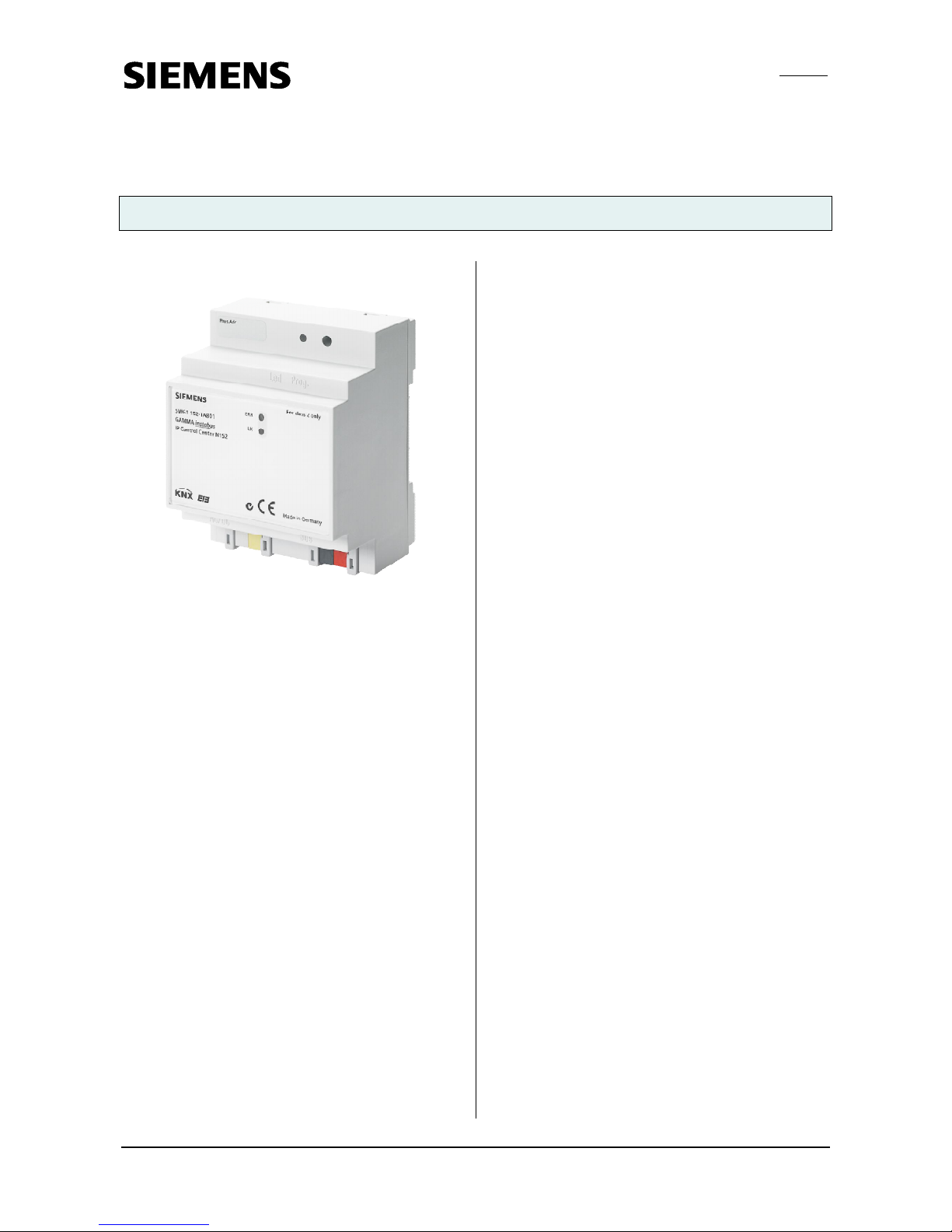
Product and function description
The IP Control Center N152 is a device for DIN-rail
mounting.
It offers the following functions:
· A web server for operating and observing KNX systems is incorporated in this device.
· A standard web browser displays the operating pages,
(tested browsers, see application program description)
· A graphics web editor projects a fully graphic view with
control and display elements in various styles.
· Application modules:
- Time switch schedules with up to 300 time switch
commands per week
- Scenes module with up to 5000 scenes or events
- Full graphic Logic module with up to 1000 Logic
functions
- Alarm functi on with up to 250 different alarm mes-
sages
- Email function with up to 20 contacts
are configured via a graphics web editor.
· An additional smart editor allows the intuitive and
quick preparation of simple visualisations for smartphones with mobile browser or for room control units.
· It provides an interface to KNX installations via data
networks, using the Internet Protocol (IP). Concurrently, this device provides communication f rom KNX
devices with PCs or other data processing equipment
(KNXnet/IP tunnelling).
The device is configured with the settings using ETS 3/4.
It defines the data types for the 250 available KNX
communications objects and provides basic information
for the device and for network settings.
The following data types can be chosen at the parameter
setting of the communication objects:
· 1 bit
· 1 Byte (0…100%)
· 1 Byte unsigned
· 1 Byte signed
· 2 Byte unsigned
· 2 Byte signed
· 2 Byte float
· 4 Byte unsigned
· 4 Byte signed
· 4 Byte float
· 14 Byte text
Further 1000 group addresses can be linked together directly with the visualisation components.
The following default settings can be placed on the device:
· The IP address of the device is assigned by ETS configuration or automatically by a DHCP service in the IP
network. Assigning of the IP address by a DHCP service allows changes to the IP address without configuring the device with the ETS.
· When configuring the device with a fixed IP address
and subnet mask, a standard gateway or router can
also be defined. This gives subscribers the opportunity
to access the Internet or another network.
If you have queries on setting the parameters IP address of the device and subnet masks, as well as
DHCP, you should contact your local network administrator.
· You can set the port number of the integrated web
server.
· Web pages for viewing and the web editor can be protected separately with different passwords.
· The device can be set both as a time master (synchronisation by time server via I P) and as a time slave
(synchronisation by KNX telegrams).
· A further parameter sets a read r equirement. This will
send an update to the object values after a restart/bus
reset.
The device is delivered with a preset IP setti ng:
Delivery status:
IP address: 192.168.1.133
Additional Information
http://www.siemens.com/gamma
Page 2
GAMMA instabus
Technical Product Information
Decem ber 2014
IP Control Center N152 5WG1 152-1AB01
Technical Manual N 152, 4 Pages Siemens AG
Infrastructure & Cities Sector, Building T echnologies
Update: http://www.siem ens.com/gamma ã Siemens AG 2014 Control Products and Systems
Subject to change without further notice. P. O. Box 10 09 53, D-93009 Rege nsburg
2.11.1.15/2
Installation Instructions
The device can be used for permanent interior installations in dry locations within distribution boards or small
casings with DIN rail EN 60715-TH35-7.5.
Υ
WARNING
· The device may only be installed and commissioned
by a licensed electri cian.
· Exposed sections of rail with integrated data rails are
to be covered with the cover 5WG1 192-8AA01.
· The relevant safety and accident prevention rules are
to be obeyed.
· The device must not be opened.
· When planning and installing electrical systems, the
relevant national directives, rules and regulations of
the country in question are to be obeyed.
Technical Specifications
Power supply
· Bus voltage: supplied via the KNX bus line
· Operating voltage:
from an external SELV power supply DC 24 V
nominal,
permissible input voltage range: DC 12 ... 30 V,
(for class 2 only),
· Power consumption: max. 1,2 W @ 24 V DC
· Recommended power supplies:
–LOGO! Power 24 V / 1,3 A, (class 2),
Rated input voltage AC 100…240 V wide range,
Input voltage range AC 85…264 V,
Constant current supply DC 24 V / 1,3 A,
Rated output voltage: DC 24 V,
Width: 3 SU
– LOGO! Power 24 V / 2,5 A,
Rated input voltage AC 100…240 V wide range,
Input voltage range AC 85…264 V,
Constant current supply DC 24 V / 2,5 A,
Rated output voltage: DC 24 V,
Width: 4 SU
– LOGO! Power 24 V / 4 A,
Rated input voltage AC 100…240 V wide range,
Input voltage range AC 85…264 V,
Constant current supply DC 24 V / 4 A,
Rated output voltage: DC 24 V,
Width: 5 SU
Network communication
· IP-connection via Ethernet, speed 100 Mbit / second
· IP address allocation via DHCP service or fixed IP ad-
dress
Connections
· Bus line: Bus terminal (black-red), without screws
0,6...0,8 mm Ø single core
Insulation st rip length 5 mm
· Ethernet 10/100 Mbps, connection: RJ45 socket
· Power supply:
Bus terminal (yellow-white), without screws
0,6...0,8 mm Ø single core
Insulation st rip length 5 mm
Control elements
· 1 learning button:
to change between normal and addressing modes
Display elements
· 1 red LED: ERR-LED signals fault status
· 1 yellow LED: LK-LED signals device Ethernet readi-
ness
· 1 red LED: to indicate normal mode / addressing mode
Mechanical specifications
· Dimensions: DIN-rail mounted device,
Width 4 SU (1 SU = 18 mm), height 55 mm
· Fire load: approx. 3.300 kJ
· Weight: approx. 150 g
Electrical safety
· Degree of contamination: 2
· Type of protection (to EN 60529): IP 20
· Protection class: (to IEC 1140) III
· Overvoltage category: III
· Bus: Safety Extremely Low Voltage SELV DC 24 V
Reliability
Failure rate: 795 fit according SN29500
EMC criteria
· Meets EN 50428:2005 + A1:2007 + A2:2009 and
EN 61000-6-2:2005, EN 61000-6-3:2007 + A1:2011
Page 3

GAMMA instabus
Technical Product Information
December 2014
IP Control Center N152 5WG1 152-1AB01
Siemens AG N 152, 4 Pages Technical Manual
Infrastructure & Cities Sector, Building T echnologies
Control Products and Systems ã Siemens AG 2014 Update: http://www.siem ens.de/gamma
P. O. Box 10 09 53, D-93009 Rege nsburg Subject to change wihout further notice
2.11.1.15/3
Environmental specifications
· Climatic conditions: EN 60721-3-3 class 3k5
· Ambient temperature in operation: -5 °C ... + 45 °C
· Storage temperature: - 25 ... + 70 °C
· Relative humidity (non-condensing): 5% to 93%
Marking
• KNX EIB
CE mark
Complies with the EMC regulations (residential and functional buildings) and low voltage regulations.
Location and Function of the Display and Operating Elements
Figure 1: Location of the display and operating elements
A1 DC 24 V bus connector terminal (yellow-white)
A2 KNX bus connector terminal (black-red)
A3 Ethernet RJ45 socket
A4 KNX programming LED
A5 KNX learning button
A6 ERR: Error status LED
A7 LK: Ethernet Activity + Communication LED
The device connections and the elements needed for
KNX commissioning - learning button and programming
LED - are accessible in the distribution board only when
the lid is removed.
Mounting and wiring
General description
The N-system DIN-rail device can be installed in distribution boards, surface or flush mounted, or on any DIN rail
complying with EN 60715-TH35-7,5.
The connection to the bus line is established via the bus
connector terminal (red-black) on the top side.
The RJ45 socket on the device front side provides the
connection to the Ethernet-IP data network.
Mounting
- Snap the IP Control Center N152 (Figure 2, B1) on to
the DIN rail (Figure 2, B2).
- Connect the auxiliary power DC 24 V with the yellow-
white bus connector terminal (Figure 1, A1).
- Connect the bus line with the black-red bus connector
terminal (Figure 1, A2).
- Plug an Ethernet patch cable with an RJ45 plug into
the RJ45 socket (Figure 1, A3) to connect the device
with the LAN/Intranet.
A connection is established to the network when the
yellow LED marked LK (Figure 1, A7) is continuously
lit.
Dismounting
- Unplug the Ethernet patch cable from the RJ45 socket
(Figure 1, A3)
- Remove the yellow-white bus connector terminal (Fig-
ure 1, A1) from its socket.
- Remove the black-red bus connector terminal (Figure
1, A2) from its socket.
- Remove the device (Figure 2, C1) with the catcher
(Figure 2, C3) from the DIN rail (Figure 2, C2)
B1
C1
C2
C3
B2
Figure 2: Mounting and dismounting a DIN-rail device
Slipping off bus connection blocks
(Figure 3)
- The bus connection block (Figure 3, D2) is situated on
the top of the device (Figure 3, D1).
- The bus connection block (Figure 3, D2) consists of
two components (Figure 3, D2.1 and D2.2) with four
ERR
LK
Page 4

GAMMA instabus
Technical Product Information
Decem ber 2014
IP Control Center N152 5WG1 152-1AB01
Technical Manual N 152, 4 Pages Siemens AG
Infrastructure & Cities Sector, Building T echnologies
Update: http://www.siem ens.com/gamma ã Siemens AG 2014 Control Products and Systems
Subject to change without further notice. P. O. Box 10 09 53, D-93009 Rege nsburg
2.11.1.15/4
terminal contacts each. Take care not to damage the
two test sockets (Figure 3, D2.3) by accidentally connecting them to the bus cable or with the screw-driver
(e.g. when attempting to unplug the bus connection
block).
- Carefully put the screw-driver to the wire-inserting slit
of the bus connection block's grey component and
pull the bus connection block (Figure 3, D2) from the
device (Figure 3, D1).
Slipping on bus connection blocks
(Figure 3)
- Slip the bus connection block onto the guide slot and
press the bus connection block (Figure 3, D2) down to
the stop.
Connecting bus cables
(Figure 3)
- The bus connection block (Figure 3, D2) can be used
with single core conductors Ø 0,6 ... 0,8 mm.
- Remove approx. 5 mm of insulation from the conduc-
tor (Figure 3, D2.4) and plug it into the bus connection
block (Figure 3, D2) (red = +, black = -).
Disconnecting bus cables
(Figure 3)
- Unplug the bus connection block (Figure 3, D2) and
remove the bus cable conductor (Figure 3, D2.4) while
simultaneously wiggling it.
D2
D
D2
D2.
4
5 mm
D2
D2.4
D2.1
D2.2
D2
D2.3
Figure 3: Connecting and disconnecting the bus wires
Slipping off / on auxiliary power connection block
- Follow the instructions for the bus connection block
when slipping off/on the auxiliary power connection
block.
Dimension Diagram
Dimensions in mm
b
90
44
55
4
5
b = 4 SU
1 Standard unit (SU) = 18 mm
General Notes
· The operating instructions must be handed over to the
client.
· Any faulty device is to be sent together with a return de-
livery note of the local Siemens office.
· If you have further questions concerning the product
please contact our technical support:
' +49 (911) 895-7222
7 +49 (911) 895-7223
* support.automation@siemens.com
www.siemens.com/automation/support-request
D1
 Loading...