

Page 1
© Siemens AG 2016
Miniature Circuit Breakers
SENTRON
Configuration
Manual
Edition
10/2015
siemens.com/lowvoltage
Page 2

© Siemens AG 2016
Page 3
Miniature Circuit Breakers
© Siemens AG 2016
2 Introduction
4 5SL miniature circuit breakers
6 5SY and 5SP miniature circuit
breakers
9 5SJ6. . . - .KS miniature circuit
breakers, with plug-in terminals
10 5SY miniature circuit breakers,
1+N in 1 MW
12 Additional components
Busbars
17 5ST standard busbars
21 5ST3 busbars acc. to UL 508
23 5ST2 distribution blocks
26 SIKclip wiring system
28 Configuration and dimensioning
29 Characteristic curves
43 Selectivity
96 Back-up protection
107 Direct current, universal current
109 5SJ4...-.HG miniature circuit breakers
acc. to UL 489 and IEC,
and accessories
112 Characteristic curves
115 Dimensional drawings
119 SHU 5SP3 main miniature circuit
breakers
121 Configuration
125 Characteristic curves
127 Dimensional drawings
129 Circuit breaker terminals
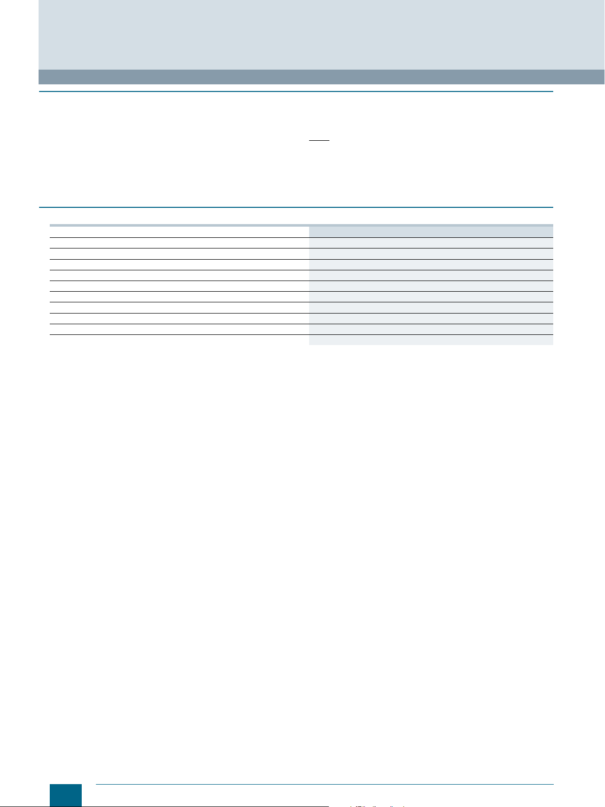
For further technical
product information:
Siemens Industry Online Support:
www.siemens.com/lowvoltage/productsupport ,
→
Entry type:
Application example
Certificate
Characteristic
Download
FAQ
Manual
Product note
Software archive
Technical data
Siemens · 10/2015
Page 4
20
40
2
1
4
10
20
40
6
60
120
Tripping time
Minutes
1.451.13
© Siemens AG 2016
Miniature Circuit Breakers
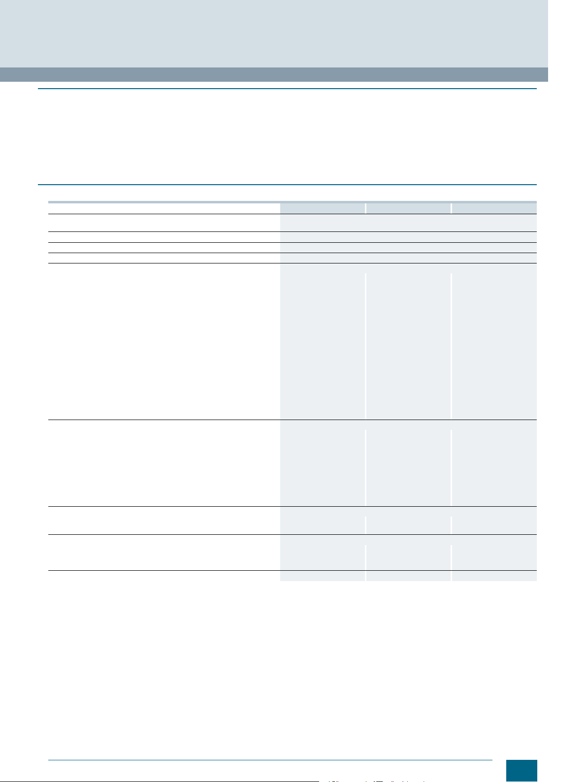
Introduction
■
Overview
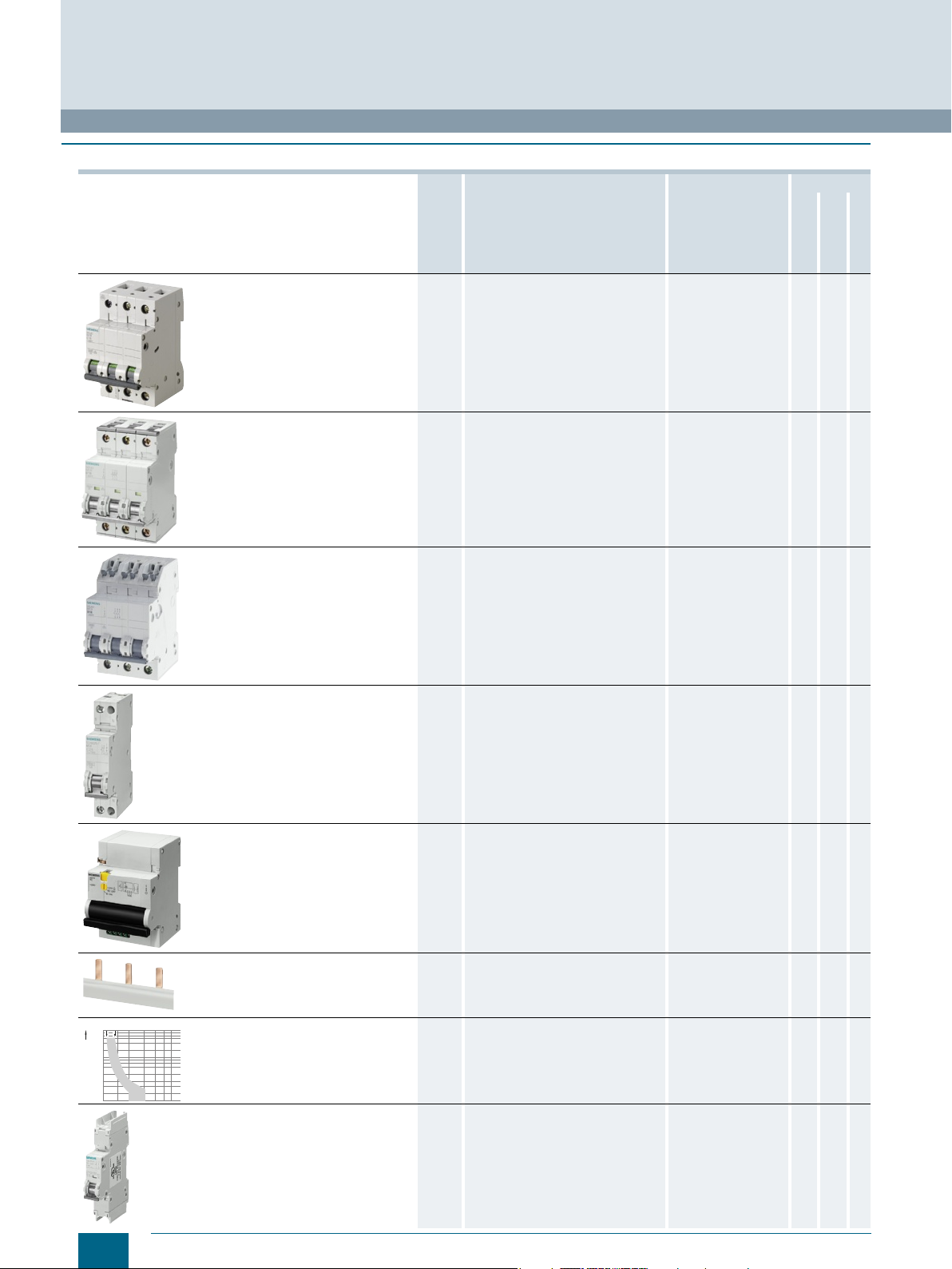
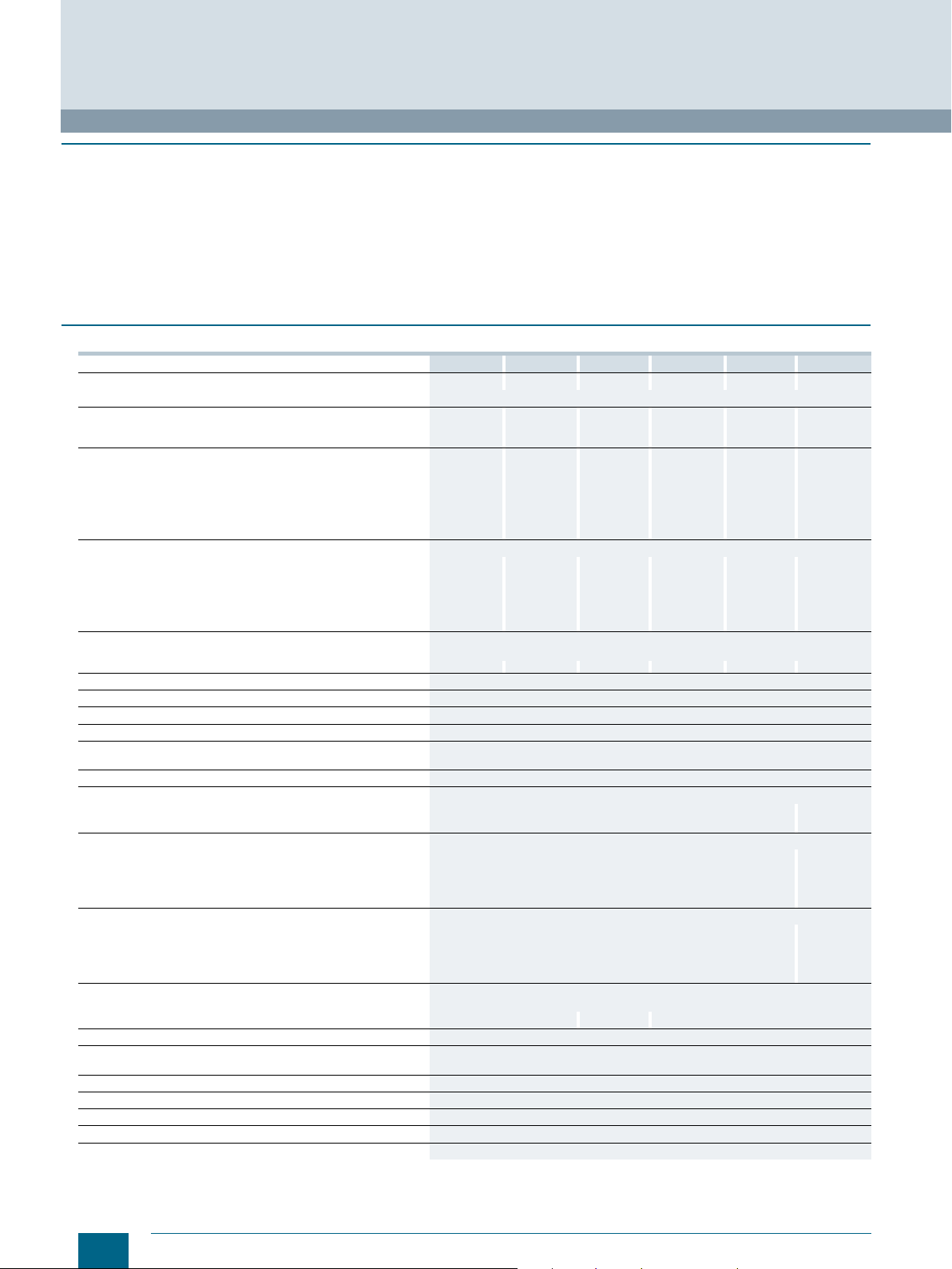
Devices Page Application Standards Used in
5SL miniature circuit breakers 4 For all applications from 0.3 A to 63 A in
the tripping characteristics B, C and D
with rated breaking capacities of
4500 A, 6000 A and 10000 A acc. to
EN 60898-1.
EN 60898-1 ✓ ✓ --
Non-residential
buildings
Residential
buildings
Industry
5SY and 5SP miniature circuit
breakers
5SJ6... -.KS miniature circuit breakers
with plug-in terminals
5SY miniature circuit breakers,
1+N in 1 MW
Additional components
6 For all applications from 0.3 A to 125 A
with rated breaking capacities 10000 A
and 15000 A acc. to EN 60898-1.
Applications for universal current from
0.3 A to 63 A, 25 kA version,
acc. to EN 60947-2.
9 For socket outlet and lighting circuits in
all building installations.
The plug-in terminals offer easy front
connection for manual insertion of
conductors, which considerably
reduces mounting times.
10 For socket outlet and lighting circuits in
all building installations where a
switchable neutral conductor is
required.
The miniature circuit breaker 1+N saves
space in the distribution board.
12 Auxiliary switches, fault signal contacts,
shunt trips, undervoltage releases for
higher system availability, RC units for
personal safety and remote controlled
mechanisms for remote switching.
EN 60898-1/-2
EN 60947-2
UL 1077
CSA 22.2
GB 10963.1/.2
-- ✓ ✓
EN 60898-1 ✓ ✓ --
EN 60898-1 ✓ ✓ ✓
✓ -- ✓
Busbars
Configuration and dimensioning
5SJ4... - .HG miniature circuit
breakers acc. to UL 489 and IEC,
and accessories
2
Siemens · 10/2015
17 Busbars in 10 mm² and 16 mm² save
space in the distribution board and time
during mounting. Busbars in 18 mm
and 25 mm
and CSA.
28 Notes for configuration, dimensioning
and extended technical specifications.
109 Miniature circuit breakers can be used
as "branch circuit protection" and are
approved for the connection type "same
polarity" and "opposite polarity" in the
characteristics B, C and D
acc. to UL489, from 0.3 to 63 A.
2
versions acc. to UL 508
UL 508 ✓ ✓ ✓
2
UL 489 ✓ ✓ ✓
Page 5
© Siemens AG 2016
Miniature Circuit Breakers
Introduction
Devices Page Application Standards Used in
Non-residential
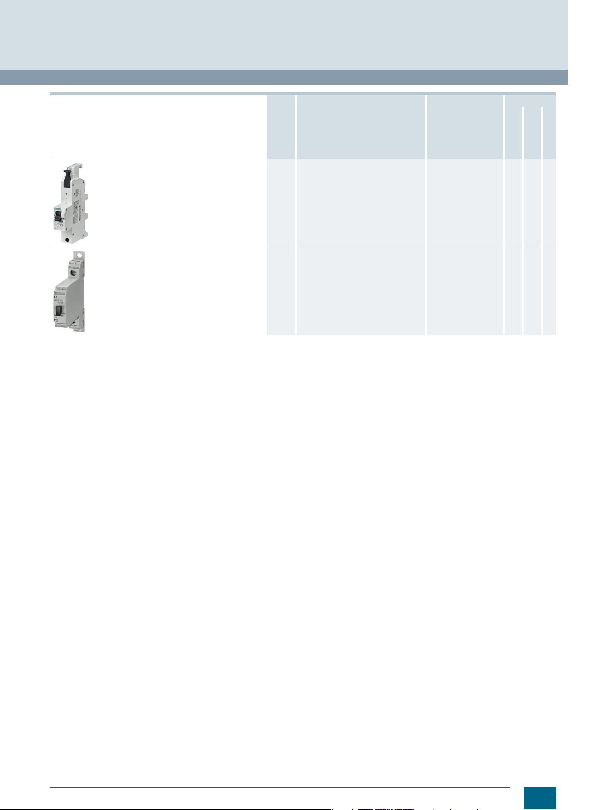
SHU 5SP3 main miniature circuit
breakers
119 Voltage-independent selective main
miniature circuit breakers (SHU) in the
precounter area support downstream
miniature circuit breakers by providing
better current limitation.
DIN VDE 0641-21 ✓ ✓ --
buildings
Residential
buildings
Industry
Circuit breaker terminals
129 Circuit breaker terminals are used for
short-circuit protection or for protection
against overload and short circuits in
auxiliary and control circuits
downstream of control transformers.
-- -- ✓
Siemens · 10/2015
3
Page 6
© Siemens AG 2016
Miniature Circuit Breakers
5SL miniature circuit breakers
■
Overview
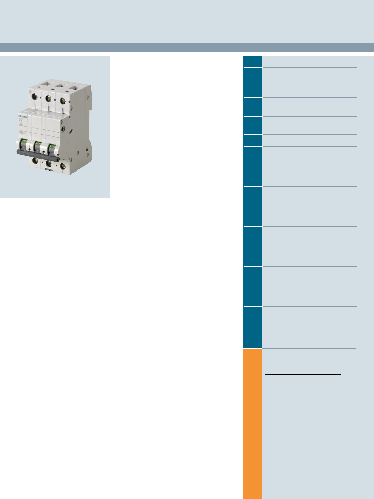
The 5SL miniature circuit breakers are intended for use up to
6 kA/10 kA. These devices have system features that are
characteristic of all Siemens miniature circuit breakers.
They are also suitable for the quick and easy mounting of
additional components, such as auxiliary switches and fault
signal contacts. The 5SL4 miniature circuit breakers can also be
combined with shunt trips, undervoltage releases and arc fault
detection devices.
■
Technical specifications
Standards EN 60898-1
Approvals
Tripping characteristic
Rated voltage U
Operational voltage
• Min. V AC/DC
•Max. V AC
Rated making and breaking capacity
• I
acc. to IEC/EN 60898-1 kA AC 4.5 6 10
cn
acc. to IEC/EN 60947-2 kA AC 4.5 6 10
• I
cu
Insulation coordination
• Rated insulation voltage V AC 250/440
• Pollution degree for overvoltage category 2/III
Rated frequency Hz 50/60
Touch protection Acc. to EN 50274 Yes
Handle end position, sealable Yes
Degree of protection IP20 with connected conductors,
CFC and silicone-free
Conductor cross-sections
• 1-wire
- Solid (≤ 10 mm2) / stranded (≥ 16 mm2)mm
- Finely stranded with non-insulated end sleeve mm
- Finely stranded with insulated end sleeve mm
- Finely stranded without end sleeve mm
• 2-wire, same cross-section, same conductor type
- Solid (≤ 10 mm2) / stranded (≥ 16 mm2)mm
- Finely stranded with non-insulated end sleeve mm
- Finely stranded with insulated end sleeve mm
- Finely stranded without end sleeve mm
• 1-wire + busbar (pin thickness 1.5 mm)
- Solid (≤ 10 mm2) / stranded (≥ 16 mm2)mm
- Finely stranded with non-insulated end
sleeve
- Finely stranded with insulated end sleeve mm
Ter mi nals ± screw (Pozidriv) 2
• Terminal tightening torque Nm
Mounting position
Service life, on average, with rated load
Storage temperature °C
Ambient temperature °C
Resistance to climate Acc. to IEC 60068-2-30
1)
The operational voltage 60 V DC/pole takes into account a battery charging voltage with a peak value of 72 V.
2)
Except: Characteristic C: 0.3 ... 1A, characteristic D: 0.3 ... 2A
n
V AC 230/400
per pole
V DC/pole
mm
To facilitate cable entry, the devices are equipped with
rectangular terminals for the accommodation of pin busbars with
cables up to 35 mm2. The rated current range is between 0.3 A
and 63 A. The 5SL miniature circuit breakers are available in
characteristics B, C and D.
5SL3 5SL6 5SL4
www.siemens.com/lowvoltage/certificates
B, C B, C, D
24
250/440
1)
60
IP40 in the area of the handle with distribution cover
Yes
2
0.75 ... 35
2
0.75 ... 25
2
0.75 ... 25
2
1 ... 35
2
0.75 ... 10
2
0.75 ... 4
2
0.75 ... 4
2
1 ... 4
2
10 ... 25
2
6 ... 25
2
6 ... 16
2.5 ... 3
Any
20000 actuations
-40 ... +75
-25 ...+45, occasionally +55, max. 95 % humidity -25 ... +55, max. 95 %
6 cycles
1)2)
60
humidity
4
Siemens · 10/2015
Page 7
I202_02133
45
90
44
70
6727254363618
1
2
5
6
1
2
N
N
1
2
3
4
123
4
123
4
56N
N
1234567
8
1
2
21N
N
123
4
NN65432
1
8
7
65432
1
© Siemens AG 2016
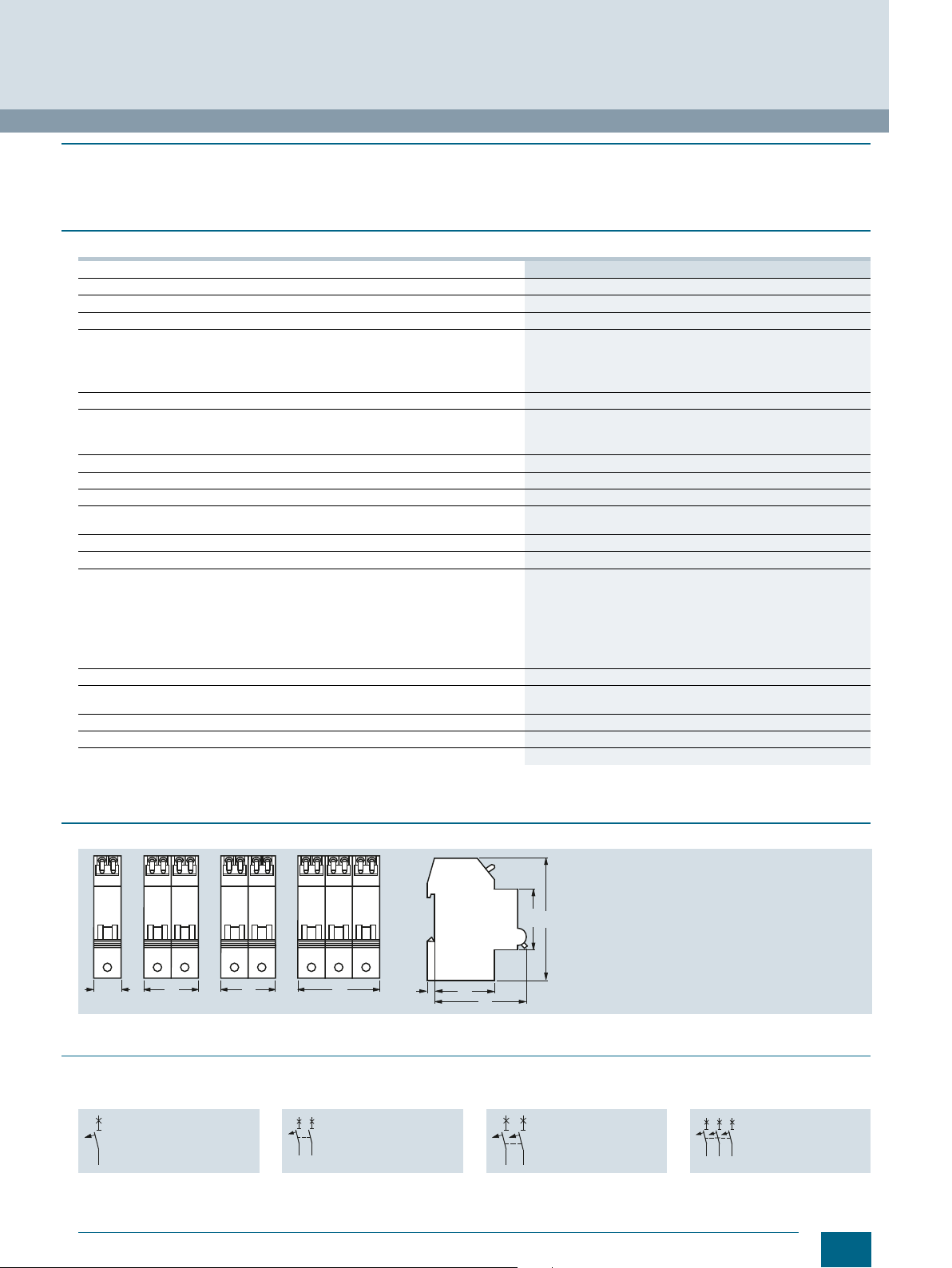
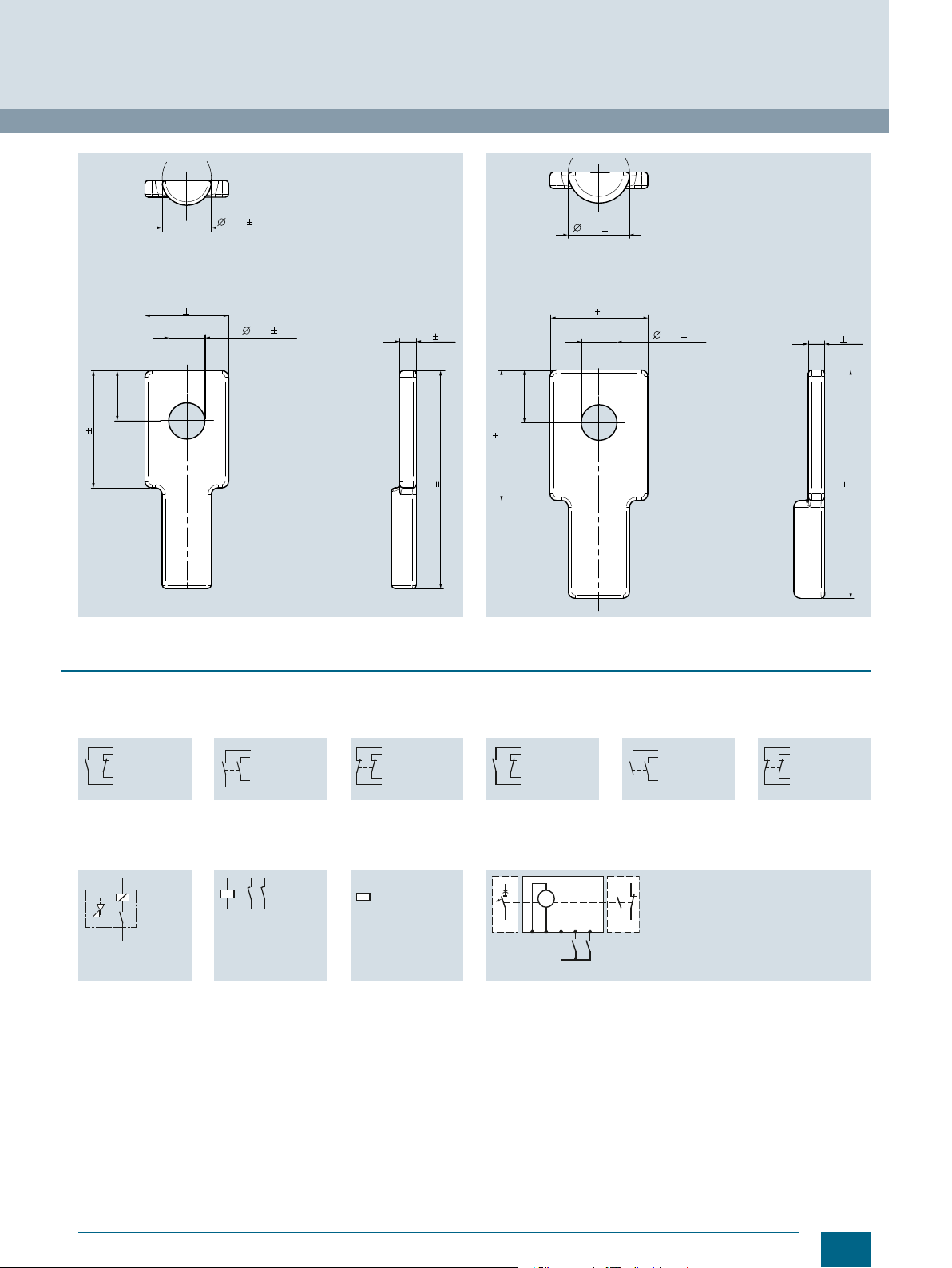
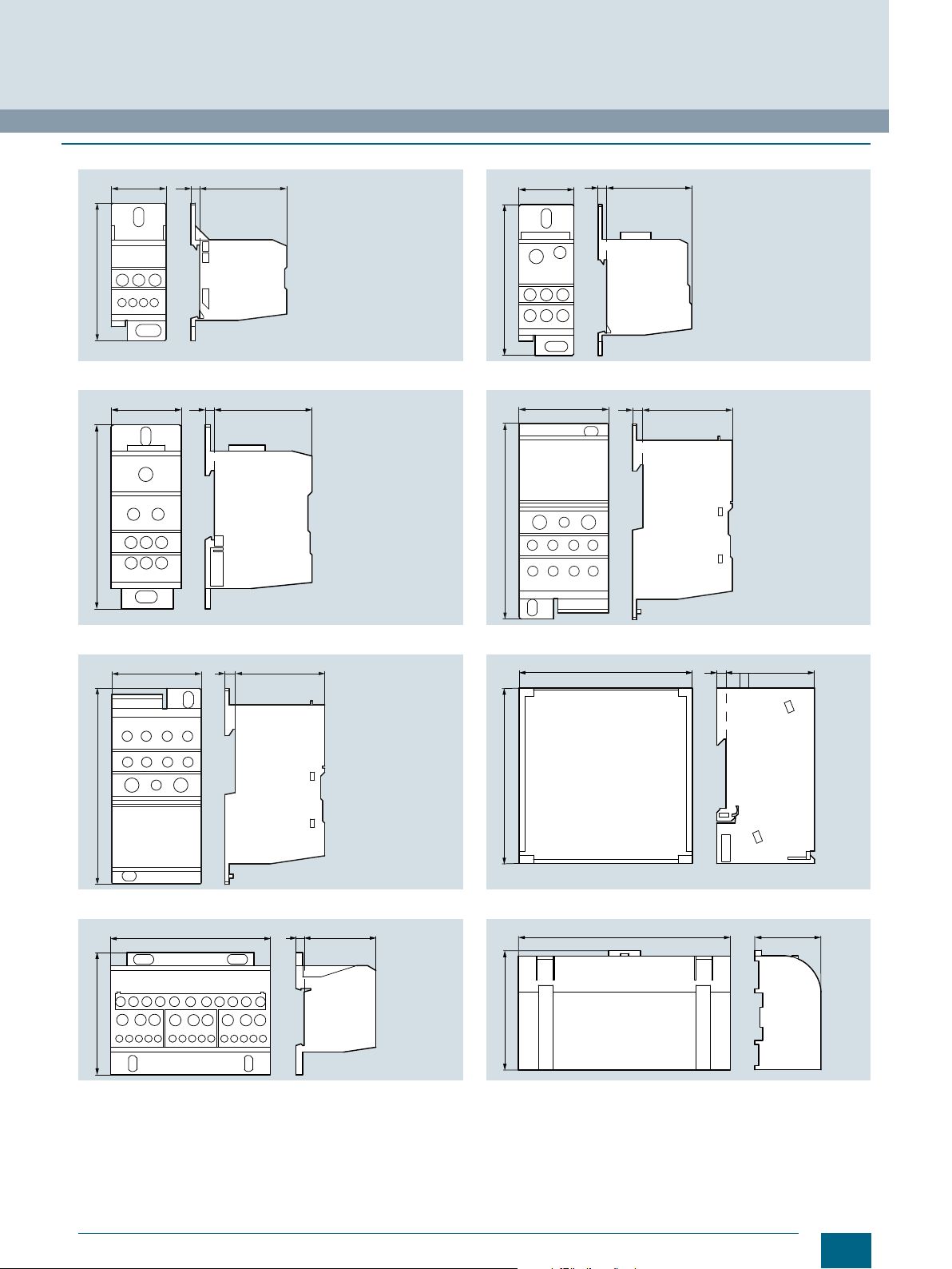
■
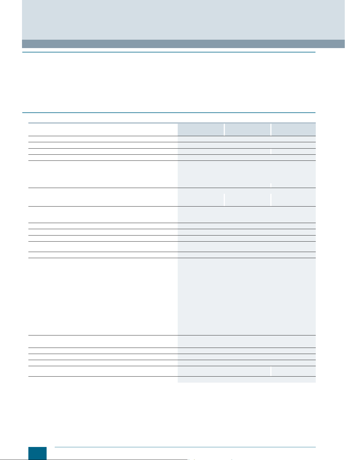
Dimensional drawings
5SL3, 5SL4, 5SL6
1P 1P+N 2P 3P 3P+N 4P
■
Circuit diagrams
Graphical symbols
5SL3, 5SL4, 5SL6
Miniature Circuit Breakers
5SL miniature circuit breakers
5
21436
1P 1P+N 2P 3P 3P+N 4P
Siemens · 10/2015
5
Page 8
© Siemens AG 2016
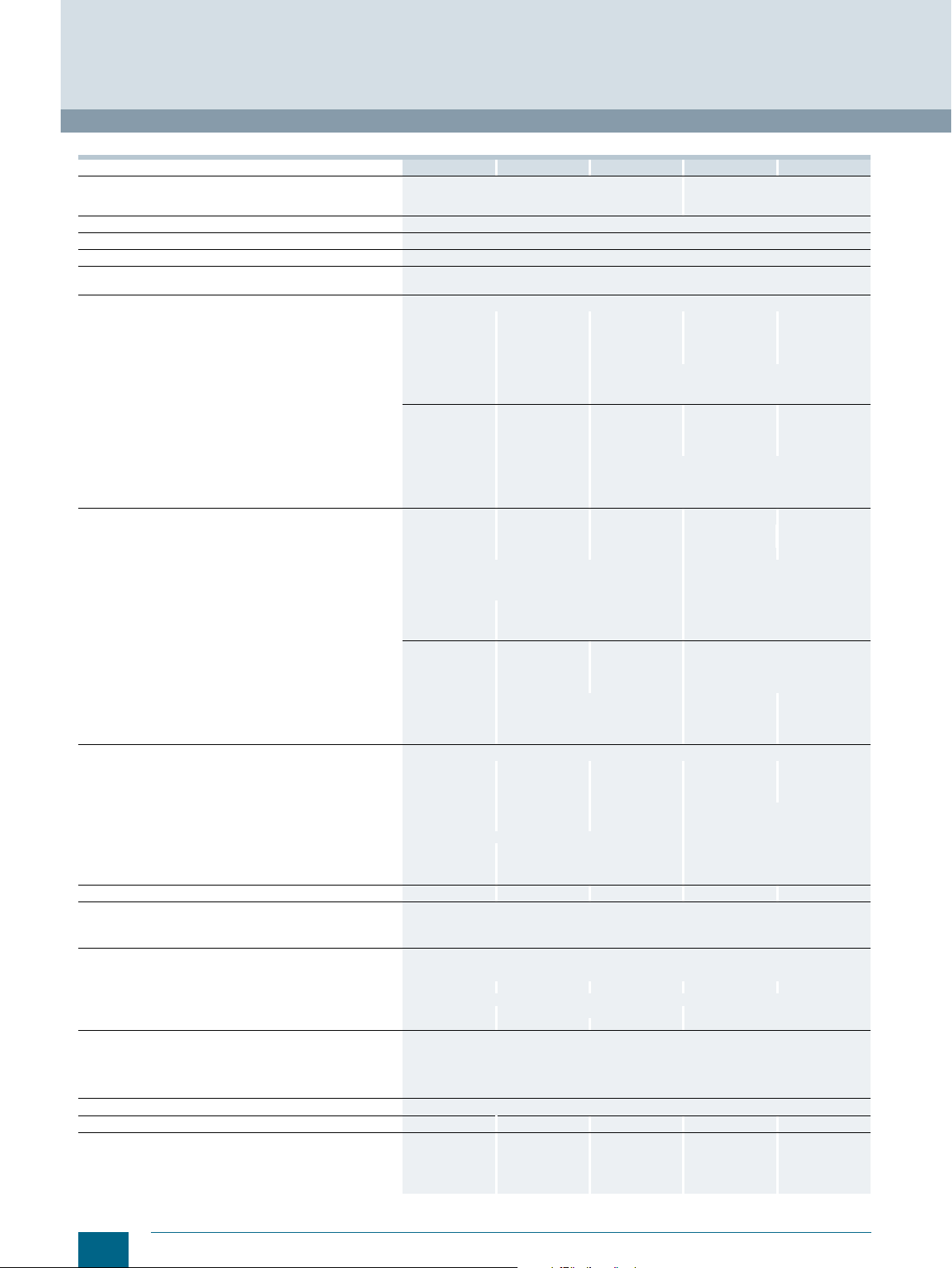
Miniature Circuit Breakers
5SY and 5SP miniature circuit breakers
■
Overview
MCBs are used to protect systems and installations in buildings
and for industrial applications.
Used in industrial applications and plant engineering, miniature
circuit breakers can be supplemented with additional
components, such as auxiliary switches, fault signal contacts,
shunt trips, undervoltage releases, remote controlled
mechanisms, RC units, and arc fault detection devices.
■
Technical specifications
5SY6 5SY4 5SY5 5SY7 5SY8 5SP4
Standards
Approvals
Rated voltage U
Operational voltage
Acc. to EN 60898-1/-2 and EN 60947-2 Max. V DC/pole
Acc. to UL 1077 and CSA C22.2 No.235 Max. V AC
Breaking capacity
• I
acc. to IEC/EN 60898-1 kA AC 6 10 10 15 -- 10
cn
acc. to IEC/EN 60898-2 kA DC 10 10 10 15 -- 10
• I
cn
• I
acc. to IEC/EN 60947-2 kA AC 30 ... 10
cu
• Acc. to UL1077 and CSA C22.2 No.235 kA AC
Insulation coordination
• Rated insulation voltage V AC 250/440
Rated frequency Hz
Pollution degree for overvoltage category
Touch protection Acc. to EN 50274 Yes
Handle end position, sealable
Degree of protection Acc. to EN 60529
CFC and silicone-free
Mounting
• Snap-on fixing system Yes --
• Standard mounting rail and screw fixing
Ter mi nals ± screw (Pozidriv)
• Tunnel terminals at both ends
• Combined terminals at both ends
• Terminal tightening torque Nm
Conductor cross-sections
• Solid and stranded mm
• Finely stranded, with end sleeve mm
•AWG cables
(Cu 60/75 °C I
Mains connection
•AC Any
•DC
Mounting position
Service life Actuations
On average, with rated load Actuations
Ambient temperature °C
Storage temperature °C
Resistance to climate Acc. to IEC 60068-2-30
Shock Acc. to IEC 60068-2-27 m/s
Resistance to vibrations Acc. to IEC 60068-2-6 m/s
1)
For detailed information, see page 28.
2)
Ensure compliance with the specified polarity when connecting DC.
3)
5SY5 4.. 4-pole, degree of pollution 2 at overvoltage category II.
n
1)
≤ 40 A; 60 °C In > 40 A)
n
V AC 230/400 230/400 230/400 230/400 230/400 230/400
V DC
Min. V AC/DC/pole 24 24 24 24 24 24
Max. V AC
Max. V DC
kA DC
V DC/pole
lb/in
2
2
AWG
2
2
EN 60898-1 EN 60898-1 EN 60898-2 EN 60898-1 EN 60947-2 EN 60898-1
www.siemens.com/lowvoltage/certificates
-- -- 220/440/
72
250/440 250/440 250/440 250/440 250/440 250/440
480Y/277 480/277 -- 480/277 480/277 480/277
60 60 -- -- -- --
15 15 15 15 15 15
5 5 -- 5 5 5
-- -- 250 -- -- --
50/60
3/III
Yes
IP20 with connected conductors,
IP40 in the area of the handle with distribution cover
Yes
-- Yes
2
-- Yes
Yes --
2.5 ... 3 2.5 ... 3.5
22 ... 26 22 ... 31
See 5SY conductor cross-sections 4 ... 50
14 ... 4 14 ... 2
Any
Any
20000
10000, for 5SY5 at 40 A, 50 A and 63 A
-25 ... +55, max. 95 % humidity
-40 ... +75
6 cycles
150 at 11 ms half-sine
50 at 25 ... 150 Hz and 60 at 35 Hz (4 sec)
The devices are approved for worldwide use according to
IEC standards for power supply systems up to 250/440 V AC.
72 V DC per pole is permitted in DC systems.
For North America, there is an additional approval according to
UL 1077 for use as "supplementary protectors" in systems up to
480/277 V AC. For use in ship building, the devices also have
numerous certifications according to shipping classifications;
BV, DNV, GL and LRS. Information on this can be found in the
Internet: www.siemens.com/lowvoltage/certificates
5)
880
4)
3)
4)
72
1)
35 ... 10
4)
Except: C/D 0.3 A ... 0.5 A
5)
5SY54.. 4-pole 880 V is not a standardized voltage acc. to EN 60898-1,
suitable for max. 1000 V DC, if the four poles are connected in series.
250 72
1)
35 ... 101)50 ... 15
2)
-- -- --
4)
Any
72
1)
70 ... 201)10
4)
72
1.5 ... 35
6
Siemens · 10/2015
Page 9

© Siemens AG 2016
Miniature Circuit Breakers
5SY and 5SP miniature circuit breakers
5SY conductor cross-sections
Number of connected conductors Solid (≤ 10 mm2) /
Stranded (≥ 16 mm
2
)
1 conductor at front (+ busbar2) rear) mm20.75 ... 35 0.75 ... 25 1 ... 25
1 conductor at rear mm20.75 ... 25 0.75 ... 16 1 ... 16
2 conductors at front1) (+ busbar2) rear) mm20.75 ... 10 0.75 ... 6 1 ... 6
2 conductors at rear1))mm
1 conductor at front/1 conductor at rear mm2f: 0.75 ... 16 r: 0.75 ... 25 f: 0.75 ... 16 r: 0.75 ... 16 f: 1 ... 16 r: 1 ... 16
1 conductor at front/2 conductors at rear1)mm2f: 0.75 ... 35 r: 0.75 ... 6 f: 0.75 ... 16 r: 0.75 ... 4 f: 1 ... 16 r: 1 ... 4
2 conductors at front
2 conductors at front
1)
Only conductors of the same cross-section and same conductor type.
2)
When bus mounting with pin busbars 5ST36.., 5ST37.., the busbars are
connected only in the rear terminal area.
3)
According to DIN 46228-4:1990, there is no finger-safety when using end
sleeves with 18 mm.
4)
The general installation regulations must be observed; finely stranded
conductors must be twisted before being inserted into the terminal; no
individual copper fibers are allowed to project after connecting to the
terminal.
1)
/1 conductor at rear mm2f: 0.75 ... 10 f: 0.75 ... 25 f: 0.75 ... 6 r: 0.75 ... 16 f: 1 ... 6 r: 1 ... 16
1)
/2 conductors at rear1)mm2f: 0.75 ... 10 r: 0.75 ... 6 f: 0.75 ... 6 r: 0.75 ... 4 f: 1 ... 6 r: 1 ... 4
2
0.75 ... 6 0.75 ... 4 1 ... 4
2
f: 25 r: 0.75 ... 16 f: 25 r: 0.75 ... 6 f: 25 r: 1 ... 6
mm
2
mm
f: 35 r: 0.75 ... 10
2
mm
Finely stranded with insulated
end sleeve
3)
Finely stranded without end
4)
sleeve
f: 25 r: 0.75 ... 2.5 f: 25 r: 1 ... 2.5
Siemens · 10/2015
7
Page 10
45
90
44
70
6
72
7
8
5
6
3
4
1
2
72
N
N
5
6
3
4
1
2
54
5
6
3
4
1
2
36
3
4
1
2
36
N
N
1
2
18
1
2
I201_13655
I201_06140
90
45
6
70
44
1
2
1
2
3
4
1
2
3
4
5
6
81
1
2
3
4
5
6
7
8
10827
54
1
2
NN1
2
123
4
8
7
65432
1
1
2
123
4
8
7
65432
1
1
2
+
-
© Siemens AG 2016
Miniature Circuit Breakers
5SY and 5SP miniature circuit breakers
■
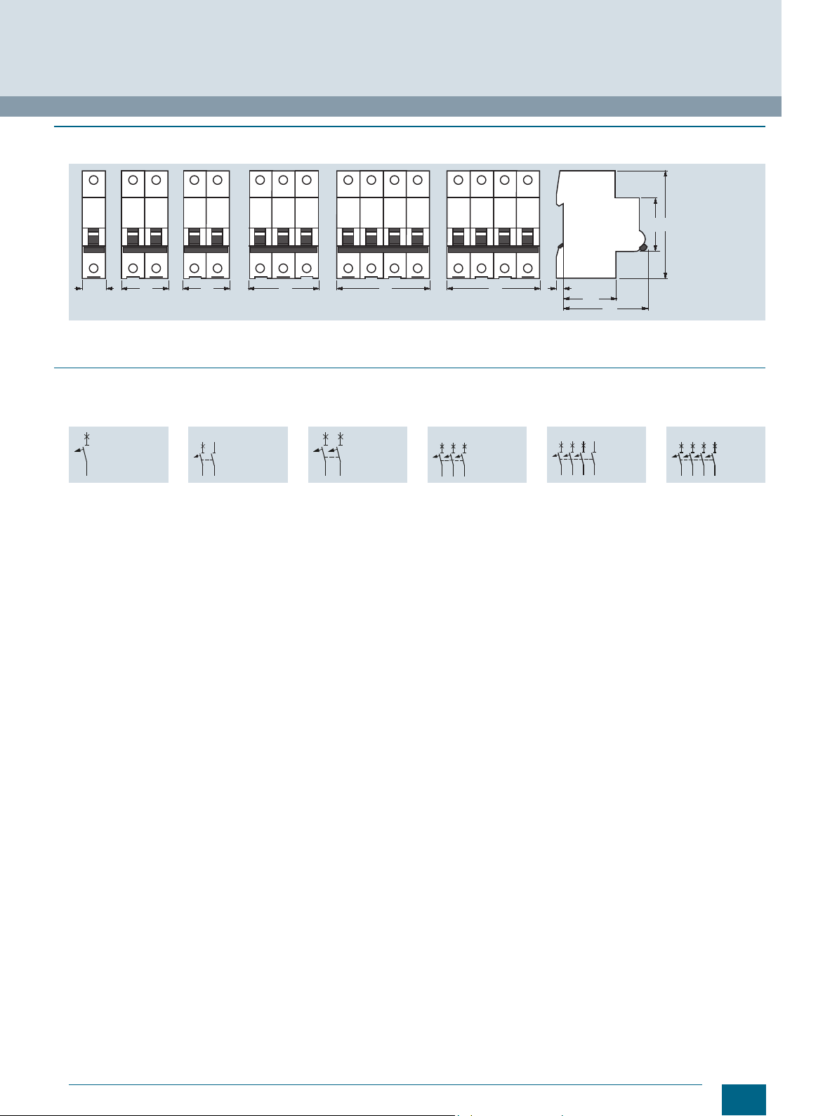
Dimensional drawings
5SY
1P 1P+N 2P 3P 3P+N 4P
5SP
1P 2P 3P 4P
■
Circuit diagrams
Graphical symbols
5SY4, 5SY6, 5SY7, 5SY8
5
21436
1P 1P+N 2P 3P 3P+N 4P
5SP4
5
21436
1P 2P 3P 4P
5SY5
-
+
123
-
+
4
1P 2P 4P
1
NN65432
-
+
1234567
-
+
++-
-
8
8
Siemens · 10/2015
Page 11
5
6
3
4
1
2
3
4
1
2
N
N
1
2
1
2
44
70
6
45
90
I201_13759
54363618
1
2
© Siemens AG 2016
5SJ6...-.KS miniature circuit breakers, with plug-in terminals
■
Overview
Miniature circuit breakers with plug-in terminals are used for the
protection of socket outlets and lighting circuits with the most
common rated currents of 10 to 20 A.
■
Technical specifications
Standards
Approvals
Rated voltage U
Operational voltage
• Min. V AC/DC/pole 24
•Max. V AC
Rated making and breaking capacity Acc. to EN 60898-1 kA AC 6
Insulation coordination
• Rated insulation voltage V AC 250/440
• Pollution degree for overvoltage category
Rated frequency Hz
Touch protection Acc. to EN 50274
Handle end position, sealable
Degree of protection Acc. to EN 60529
CFC and silicone-free
Ter mi nals
Conductor cross-sections
• Top, plug-in terminals
- Solid, stranded and finely stranded, without end sleeve
- Finely stranded, with end sleeve
• Bottom, tunnel terminal ± screw (Pozidriv)
- Solid, stranded or finely stranded,
n
with end sleeve
Mounting position
Service life
On average, with rated load
Ambient temperature °C
Storage temperature °C
Resistance to climate Acc. to IEC 60068-2-30
1)
The operational voltage 60 V DC/pole takes into account a battery
charging voltage with a peak value of 72 V.
V AC 230/400
V DC/pole
2
mm
2
mm
2
mm
Miniature Circuit Breakers
5SJ6...-.KS
EN 60898-1
www.siemens.com/lowvoltage/certificates
250/440
1)
60
2/III
50/60
Ye s
Ye s
IP20 with connected conductors,
IP40 in the area of the handle with distribution cover
Ye s
Screwless terminals on the outgoing terminals for 1.5 ... 4 mm
1.5 ... 4
1.5 ... 2.5
2
0.75 ... 25
Any
20000 actuations
-25 ...+45, occasionally +55, max. 95 % humidity
-40 ... +75
6 cycles
2
■
Dimensional drawings
1P 1P+N 2P 3P
■
Circuit diagrams
Graphical symbols
1P 1P+N 2P 3P
2
NN1
123
4
5
21436
Siemens · 10/2015
9
Page 12

© Siemens AG 2016
Miniature Circuit Breakers
5SY miniature circuit breakers, 1+N in 1 MW
■
Overview
These miniature circuit breakers are used for the protection of
systems and installations with switched neutral conductors in
distribution boards with little space. They are just a single
modular width.
■
Technical specifications
Standards
Approvals
Rated voltage U
Operational voltage
• Min. V AC/DC 24
•Max. V AC
Rated making and breaking capacity I
Insulation coordination
• Rated insulation voltage V AC 250
• Pollution degree for overvoltage category
Rated frequency Hz
Touch protection Acc. to EN 50274 Ye s
Handle end position, sealable
Degree of protection Acc. to EN 60259
CFC and silicone-free
Terminals ± screw (Pozidriv)
• Solid and stranded,
top and bottom terminal
• Finely stranded, with end sleeve,
top and bottom terminal
• Terminal tightening torque Nm
Mounting position
Service life
On average, with rated load 20000 actuations
Ambient temperature °C
Storage temperature °C
Resistance to climate Acc. to IEC 60068-2-30 6 cycles
Resistance to vibrations Acc. to IEC 60068-2-6 m/s
n
cn
V AC 230
V DC/pole
kA AC 4.5 6
mm
mm
Compact busbars facilitate installation in space-saving
distribution boards.
5SY30.. 5SY60..
EN 60898-1
www.siemens.com/lowvoltage/certificates
250
72
2/III
50/60
Yes
IP20 with connected conductors,
IP40 in the area of the handle with distribution cover
Yes
2
2
0.75 ... 16
2
0.75 ... 10
2.0 ... 2.5
Any
at 2A/4A and 40A: 8000 actuations
-25 ...+45, occasionally +55, max. 95 % humidity
-40 ... +75
2
50 at 25 ... 150 Hz and 60 at 35 Hz (4 sec)
10
Siemens · 10/2015
Page 13
■
7
70
45
90
I201_13982
18
44
12N
N
15,2
9,2
L1 L 2 L3
1 1
I201_13984
NN1
2
12N
N
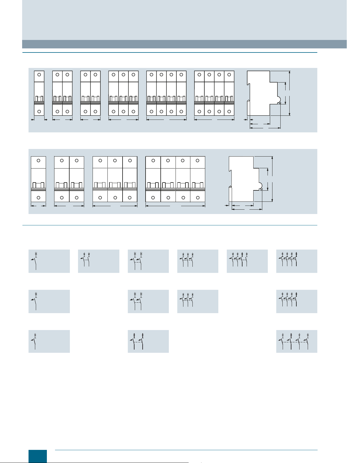
Dimensional drawings
© Siemens AG 2016
NN1
Miniature Circuit Breakers
5SY miniature circuit breakers, 1+N in 1 MW
90
45
2
18
1P+N
N pole, right
5ST36
Pin spacing in MW
Dimensions of side view in mm (approx.) Dimensions of side view in mm (approx.)
5ST3613
5ST3614
5ST3615
■
Circuit diagrams
1P+N
N pole, left
5ST37
Pin spacing in MW
1
5ST3762
5ST3764
7
I201_13680
44
70
10
5,6
Graphical symbols
1P+N
N pole, right
1P+N
N pole, left
I201_13983
1
5ST3763
5ST3765
I201_13681
10
5,6
Siemens · 10/2015
11
Page 14

Miniature Circuit Breakers
Additional components
■
Overview
The Siemens mounting concept supports the combination of all
5ST3 additional components with Siemens 5SY and 5SP
miniature circuit breakers and with 5SU1 RCBOs.
5SL and 5SY60.. miniature circuit breakers are suitable for
mounting auxiliary switches and fault signal contacts. Auxiliary
switches can also be mounted on 5TE8 flush-mounting circuit
breakers and 5SG71 MINIZED switch disconnectors.
Auxiliary switches (AS)
The auxiliary switch (AS) always signals the contact position of
the miniature circuit breaker, regardless of whether the miniature
circuit breaker was tripped manually or as the result of a fault. An
additional version is also available for the switching of small
currents and voltages for the control of programmable control
systems (PLCs) acc. to EN 61131-2. The auxiliary switch with
test button enables the testing of control circuits without the
need to switch the miniature circuit breaker.
Fault signal contacts (FC)
The fault signal contact (FC) signals the automatic tripping of the
miniature circuit breaker in the event of a fault, such as an
overload or a short circuit. If the fault signal contact is activated,
the contact position does not change if the miniature circuit
breaker is tripped manually. Fault signal contacts with TEST and
RESET buttons enable the testing of control circuits without the
need to trip the miniature circuit breaker. The red RESET button
integrated in the handle also indicates the automatic tripping of
the MCB. The signal can be acknowledged manually using the
RESET button.
Shunt trips (ST)
Shunt trips are used for the remote tripping of a miniature circuit
breaker.
Undervoltage releases (UR)
Undervoltage releases are integrated (e.g. in EMERGENCY-OFF
loops), thus ensuring that the MCB trips in the event of an
emergency, which, in turn, ensures disconnection of the control
circuit according to EN 60204. In the event that the voltage is
interrupted or too low, it also trips, i.e. prevents activation of the
MCB.
Remote controlled mechanisms (RC)
Remote controlled mechanisms are used for the remote ON/OFF
switching of miniature circuit breakers and the remote ON
switching of RC units, as well as the local manual switching of
these devices. A blocking function permits maintenance work. In
the event that a miniature circuit breaker or RC unit is tripped, an
acknowledgment must be carried out prior to switching back on.
The remote controlled mechanism has an operating mode
selector switch with the functions: "Locked", "Manual" and
"Remote Switching".
© Siemens AG 2016
Selector switch position:
OFF: The remote controlled mechanism is switched off, blocked
mechanically and can be sealed and/or locked.
RC OFF: Only manual operation is possible.
RC ON: Both manual and remote operation are possible.
In the event that a device is tripped by a fault (RC units, miniature
circuit breakers), the handle of the basic device and remote
controlled mechanism switches to the OFF position. The
operator must then acknowledge the tripping by resetting the
remote controlled mechanism (OFF command) before it can be
reactivated. This serves the safety of the installation or to protect
personnel during maintenance work.
In an RC unit/miniature circuit breaker combination, the RC unit
is switched on asynchronously, i.e. prior to the miniature circuit
breaker. The RC units for 5SY and 5SP4 can be switched ON via
the MCB handle jumper using the supplied actuator attachment.
There is no need to switch off the RC unit via the remote
controlled mechanism as the MCB contacts ensure
disconnection of the electrical circuit.
The switching frequency is max. 2 actuations per minute. If this
actuation frequency is exceeded it may cause internal tripping
of the remote controlled mechanism as a protection against
possible overload. In this case, the remote controlled
mechanism must be switched OFF at the function selector
switch and not switched back on again for at least 5 minutes.
More additional 5ST3 ... components, such as AS, FC, ST and
UR, can be added to the right-hand side of the remote controlled
mechanism in line with the Siemens mounting concept.
RC units
RC units can be combined with miniature circuit breakers of
characteristic A, B, C and D. They then form a combination of
RCCB and MCB for personnel, fire and line protection. The
combinations can be tailored to meet individual requirements.
For information on RC units, see chapter "Residual Current
Protective Devices / Arc Fault Detection Devices (AFDDs)" in
Catalog LV 10.
12
Siemens · 10/2015
Page 15
© Siemens AG 2016
Miniature Circuit Breakers
Additional components
■
Technical specifications
Auxiliary switches (AS) Fault signal contacts (FC)
Standards
Approvals
Short-circuit protection
5ST3010, 5ST3010-2
5ST3011, 5ST3011-2
5ST3012, 5ST3012-2
EN 62019; IEC/EN 60947-5-1; UL 1077; CSA C22.2 No. 235
www.siemens.com/lowvoltage/certificates
Miniature circuit breaker or gG 6 A fuse
5ST30131), 5ST3013-2
5ST30141), 5ST3014-2
5ST30151), 5ST3015-2
Contact load
•Min. 50 mA, 24 V 1 mA/5 V DC 50 mA, 24 V
•Max.
• 400 V AC, AC-14, NO A
• 230 V AC, AC-14, NO A
• 400 V AC, AC-13, NC A
• 230 V AC, AC-13, NC A
• 220 V DC, DC-13, NO+NC A
• 110 V DC, DC-13, NO+NC A
• 60 V DC, DC-13, NO+NC A
• 24 V DC, DC-13, NO+NC A
Service life, on average, with rated load
Conductor cross-sections mm
--
2 -- 2
6 -- 6
2 -- 2
6 -- 6
1 -- 1
1 -- 1
3 -- 3
6 -- 6
20000 actuations 20000 actuations 20000 actuations
2
0.5 ... 2.5 0.5 ... 2.5 0.5 ... 2.5
AWG
22 ... 14 22 ... 14 22 ... 14
1)
= 100 mA/30 V DC
2)
= 50 mA/30 V DC
Ter mi nals
• Terminal tightening torque Nm 0.5 0.5 0.5
Rated frequency Hz
Mounting position
lb/in
4.5 4.5 4.5
50/60
Any Any Any
Ambient temperature °C -25 ... +55 -25 ... +55 -25 ... +55
Storage temperature -40 ... +75 -40 ... +75 -40 ... +75
Resistance to climate Acc. to IEC 60068-2-30 Cycles 28
Shock Acc. to IEC 60068-2-27 m/s
Resistance to vibrations Acc. to IEC 60068-2-6 m/s
50 at 11 ms half-sine
2
50 at 10 ... 150 Hz
Undervoltage
releases (UR)
Shunt trips (ST) Remote controlled
5ST304. 5ST3030 5ST3031 5ST3050, 5ST3052
Standards
Rated voltages U
• Operating rangeU
• Rated frequency f
n
n
n
EN 60947-1
V AC 230 110 ... 415 24 ... 48 230
24, 110 110 24 ... 48 --
V DC
0.85 ... 1.1 x U
n
0.7 ... 1.1 x U
n
Hz -- 50 ... 60 50 ... 60
Response limits
• Tripping < 0.35 ... 0.7 × U
Short-circuit protection
Minimum contact load
Tripping operations
Service life, on average, with rated load
Conductor cross-sections mm
Ter mi nals
• Terminal tightening torque Nm 0.8 0.8 0.4 ... 0.5
Mounting position
Miniature circuit breakers B/C 6 A or fuse gG 6 A
50 mA, 24 V 50 mA, 24 V --
max. 2000 max. 2000 --
20000 actuations 20000 actuations 20000 actuations
2
0.5 ... 2.5 0.5 ... 2.5 0.5 ... 2.5
22 ... 14 22 ... 14 22 ... 14
AWG
6.8 6.8 4.5
lb/in
Any Any Any
-- --
n
Ambient temperature °C -25 ... +55 -25 ... +55 -20 ... +55
Storage temperature °C -40 ... +75 -40 ... +75 -40 ... +75
Resistance to climate Acc. to IEC 60068-2-30 Cycles 28
Shock Acc. to IEC 60068-2-27 m/s
Resistance to vibrations Acc. to IEC 60068-2-6 m/s
Switching frequency
Switching duration s
50 at 11 ms half-sine
2
50 at 10 ... 150 Hz
-- 2 actuations per minute
-- < 2
Minimum command duration s -- 0.2 continuous command possible
Rated power dissipation VA
Rated frequency Hz
Behavior in the event of control voltage failure
-- No intrinsic consumption,
50/60
-- No change
Technical specifications for the RC units can be found in chapter "Residual Current Protective Devices / Arc Fault Detection Devices
(AFDDs)" in Catalog LV 10.
2)
5ST3020, 5ST3020-2
2)
5ST3021, 5ST3021-2
2)
5ST3022, 5ST3022-2
--
mechanisms (RC)
0.9 ... 1.15 x U
n
5000 at RC unit
in switching operation 26
Siemens · 10/2015
13
Page 16
Miniature Circuit Breakers
45
90
44
70
618
9
I201_13657
90
9
I202_02032
Additional components
■
Dimensional drawings
© Siemens AG 2016
I201_12624a
90
45
44
63
736
74
5ST3010
5ST3011
5ST3012
5ST3013
5ST3014
5ST3015
5ST3020
5ST3021
5ST3022
5ST3010-2
5ST3011-2
5ST3012-2
5ST3013-2
5ST3014-2
5ST3015-2
Z\
YX
Z_Z_
5ST3030
5ST3031
5ST3040
5ST3041
5ST3042
5ST3043
5ST3044
5ST3045
I202_02033
5ST3050
5ST3052
45
90
70
]W
^S _
\^S`
90
I202_02032
9
5ST3020-2
5ST3021-2
5ST3022-2
I202_02033
70
Z]S[
45
90
^W
^WGG^W
npYWY ZZ`^^
5ST3060
5ST3061
YW
YX[
14
Siemens · 10/2015
Page 17
22
14
13
21
24
14
13
23
22
12
11
21
22
14
13
21
22
12
11
21
C2
C1
<
242314
13
U
D1
D2
v
U
D1
D2
P, N: Supply voltage
1: Return conductor
2: ON command
3: OFF command
© Siemens AG 2016
Miniature Circuit Breakers
Additional components
WSX\
X[S_
Y\
WSZ
XWS_
WSX\
\
WSY
X_S`
ZW
WSX\
WSZ
XWS_ WSX\
\
WSY
X
T
X\
WSY
Z\
WSZ
]\
npYWY Z Z`^_
X
T
X]
[W WSY
5ST2510 5ST2512
■
Circuit diagrams
Graphical symbols
Auxiliary switches (AS) Fault signal contacts (FC)
5ST3010
5ST3013
5ST3010-2
5ST3011
5ST3014
5ST3011-2
5ST3012
5ST3015
5ST3012-2
5ST3020
5ST3020-2
npYWYZZ`^`
13
23
24
14
5ST3021
5ST3021-2
5ST3022
5ST3022-2
^W WS Z
Shunt trips (ST) Undervoltage releases (UR) Remote controlled mechanisms (RC)
M
321NP
I201_10741a
ON OFF
5ST3030
5ST3031
5ST3040
5ST3041
5ST3042
5ST3043
5ST3044
5ST3045
5ST3050
5ST3052
Siemens · 10/2015
15
Page 18
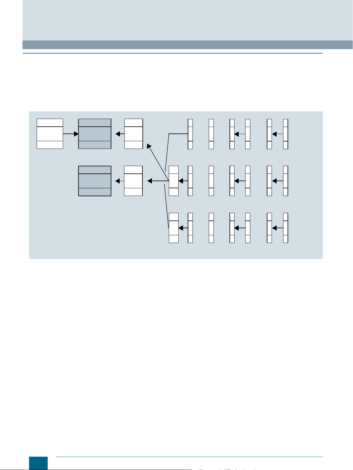
Miniature Circuit Breakers
or
or or or
or or or
5ST3
RC unit MCB RC
AS FC
ASFCAS
FC
ASFCFC
AS
AS FC
ASFCAS
FC
ASFCFC
AS
AS FC
ASFCAS
FC
ASFCFC
AS
ST
UR
or or
5SM2 5SY / 5SP4
RCBO
RC
5SU1
RC unit: Residual current unit
MCB: Miniature circuit breaker
RCBO: Residual current operated circuit breaker
RC: Remote controlled mechanism
UR: Undervoltage release
ST: Shunt release
AS: Auxiliary switch
FC: Fault signal contact
I201_18123a
Additional components
■
More information
The Siemens mounting concept supports the combination of all
5ST3 additional components with miniature circuit breakers of
the 5SY, 5SP and 5SL4 series and RCBOs of the 5SU1 series.
5SL and 5SY60.. miniature circuit breakers are suitable for
mounting auxiliary switches and fault signal contacts. Auxiliary
switches can also be mounted on 5TE8 flush-mounting circuit
breakers and 5SG71 MINIZED switch disconnectors.
© Siemens AG 2016
The diagram shows which additional components can be
mounted on either the right or the left.
Mounting concept for RCBOs, see chapter "Residual Current Protective Devices / Arc Fault Detection Devices (AFDDs)" in
CatalogLV10.
16
Siemens · 10/2015
Page 19
S
I201_13755
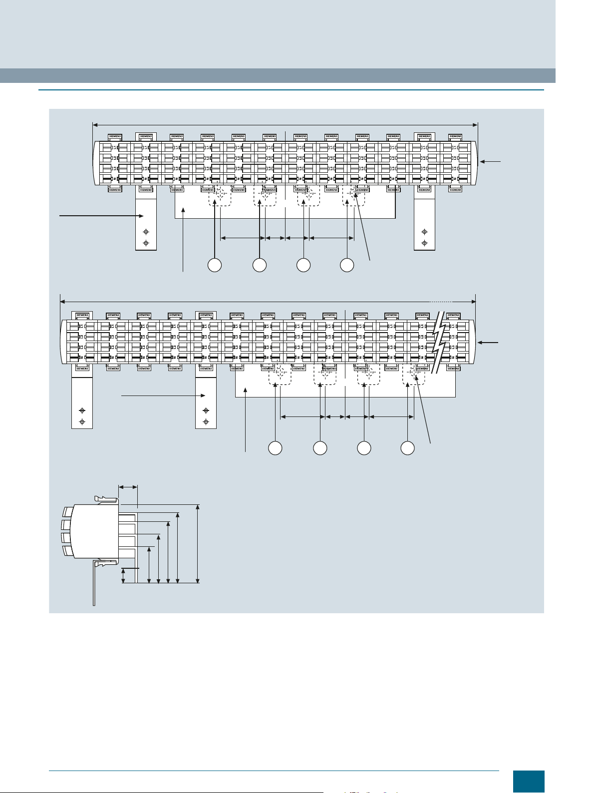
© Siemens AG 2016
■
Overview
The busbar system with pin-type connections can be used for all
5SL6, 5SJ6 ...-.KS and 5SY miniature circuit breakerswith or
without mounted auxiliary switch (AS) or fault signal
contact (FC).
2
Busbars in 10 mm
and 16 mm2 versions are available.
With bars that can be cut to length, the 5ST37 busbar system
can be tailored to any requirements.
The extremely flexible 5ST36 busbar system with fixed lengths
also enables installation in any length as the busbars can be
No further need for time-consuming tasks, such as cutting,
cutting to length, deburring, cleaning of cut surfaces and
mounting of end caps.
Any free pins on the busbars can be made safe by covering with
touch protection.
Further information on the bus-mounting of miniature circuit
breakers with residual current operated circuit breakers, see
chapter "Residual Current Protective Devices / Arc Fault
Detection Devices (AFDDs)" in Catalog LV 10.
overlapped.
■
Technical specifications
5ST3
Standards
Busbar material
Partition material
Rated operational voltage U
Rated current I
• Cross-section 10 mm
• Cross-section 16 mm
Rated impulse withstand voltage U
Test pulse voltage (1.2/50) kV
Rated conditional short-circuit current I
Resistance to climate
• Constant atmosphere Acc. to DIN 50015 23/83; 40/92; 55/20
• Humid heat Acc. to IEC 60068-2-30
Insulation coordination
• Overvoltage category III
• Pollution degree
Maximum busbar current I
• Infeed at the start of the busbar
- Cross-section 10 mm
- Cross-section 16 mm
• Infeed at the center of the busbar
- Cross-section 10 mm
- Cross-section 16 mm
n
c
2
2
imp
cc
/phase
S
2
2
2
2
V AC 400
A 63
A 80
kV 4
kA 25
A 63
A 80
A 100
A 130
EN 60439-1 (VDE 0660-500): 2005-01
SF-Cu F 24
Plastic Cycoloy 3600,
heat-resistant above 90 °C,
flame-retardant,
self-extinguishing,
free of dioxins and halogens
6.2
28 cycles
2
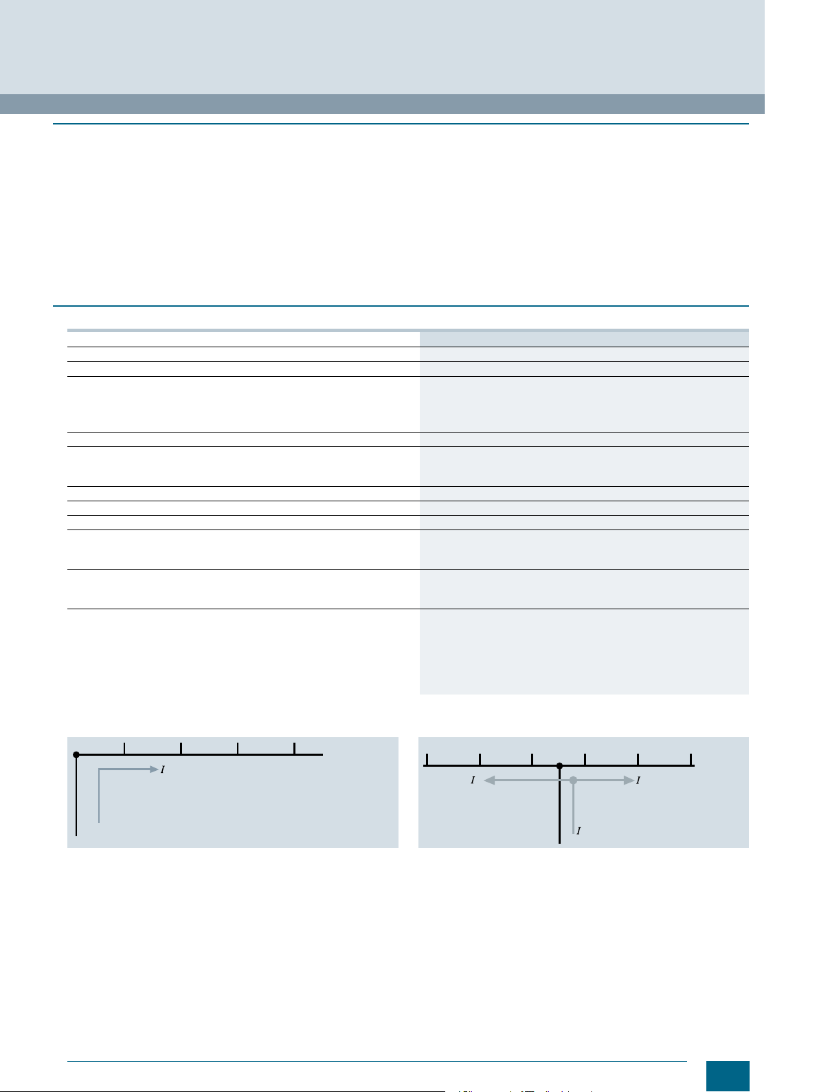
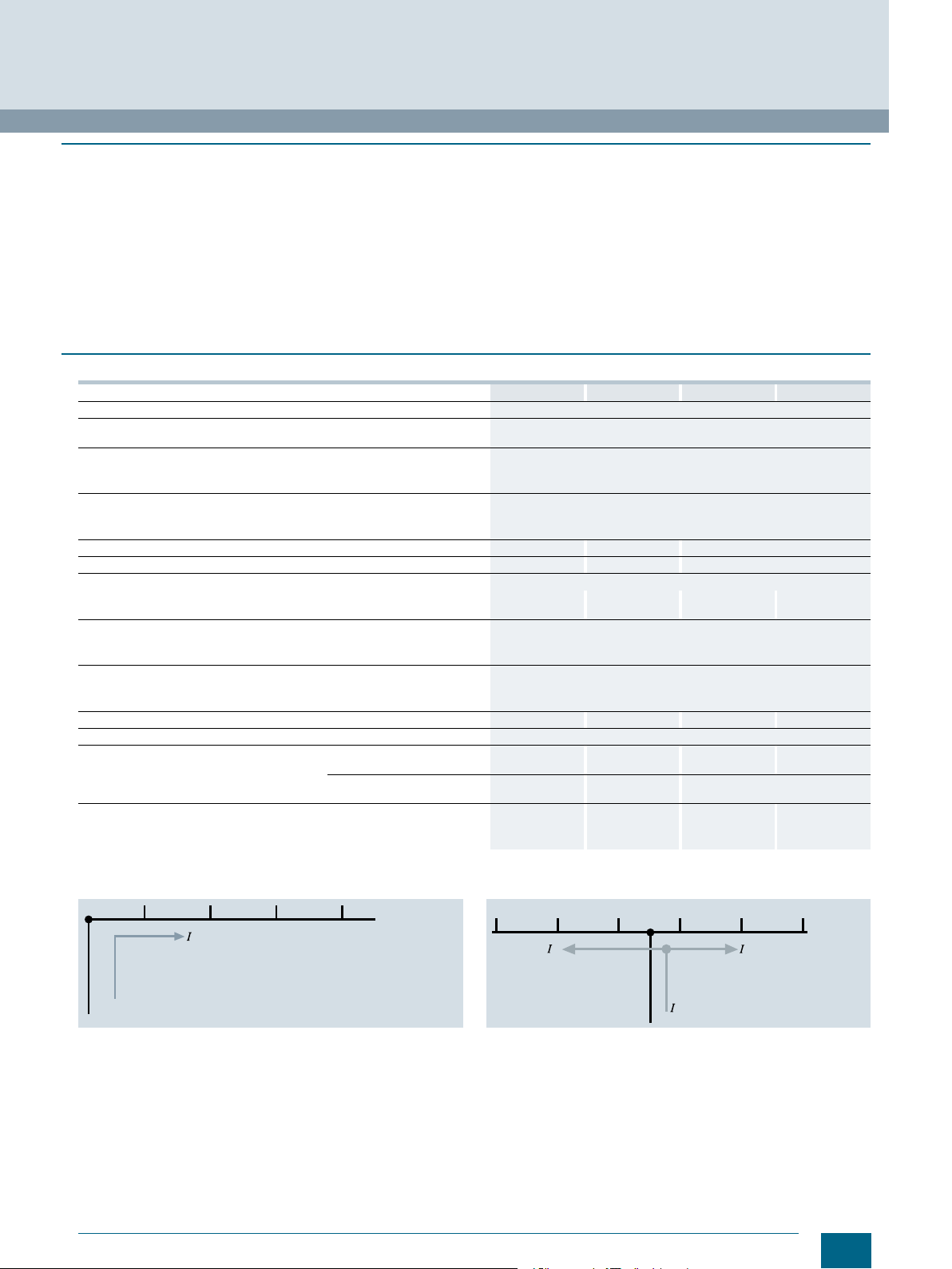
Miniature Circuit Breakers
Busbars
5ST standard busbars
Infeed at the start or end of the busbar Infeed along the busbar or midpoint infeed
321
S1
The sum of the outgoing current per branch (1, 2, 3...n) must not be greater
than the max. busbar current I
/phase.
S
1
S
Siemens · 10/2015
2 3
S2
I201_13754a
17
Page 20
Miniature Circuit Breakers
14
3,4
1
1
1,5
I201_13663
1,5
L1 L2
15,2
6,6
I201_13666
1
19
7,3
L1 L2
1
L1 L2
1 1,5
I201_13664
15,2
9,2
L1 L2 L3
1 1
L1 L2 L3
1 1 1,5
I201_13668a
L1 L2 L3
1,51,5 1,5
L1 L2 L3
1 1
L1 L2 L3
1 1 1,5
I201_13669a
L1 L2 L3
1,51,5 1,5
19
10,3
15,2
11,8
L1 L2 L3 N
1 1 1
L1 L2 L3 NNN
I201_13670
1 1 1 1 1
1,5
19
13,3
L1 L2 L3 N
1 1 1
L1 L2 L3 NNN
I201_13671
1 1 1 1 1
1,5
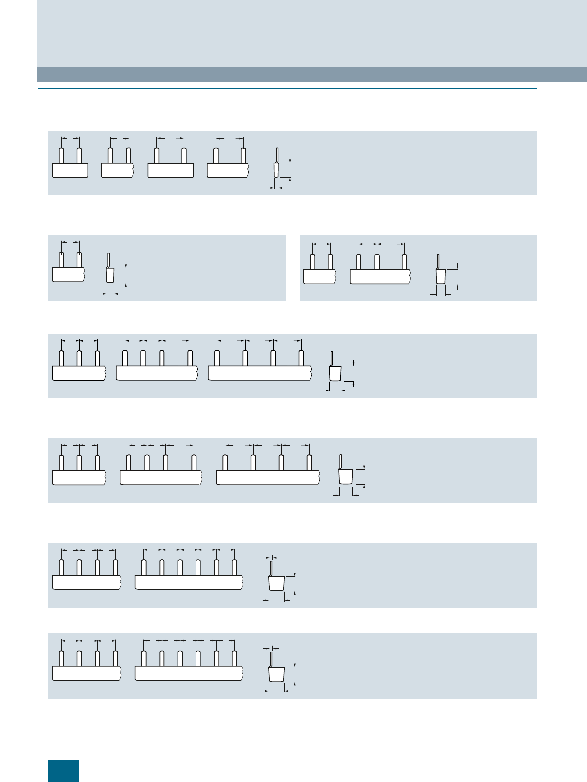
Busbars
5ST standard busbars
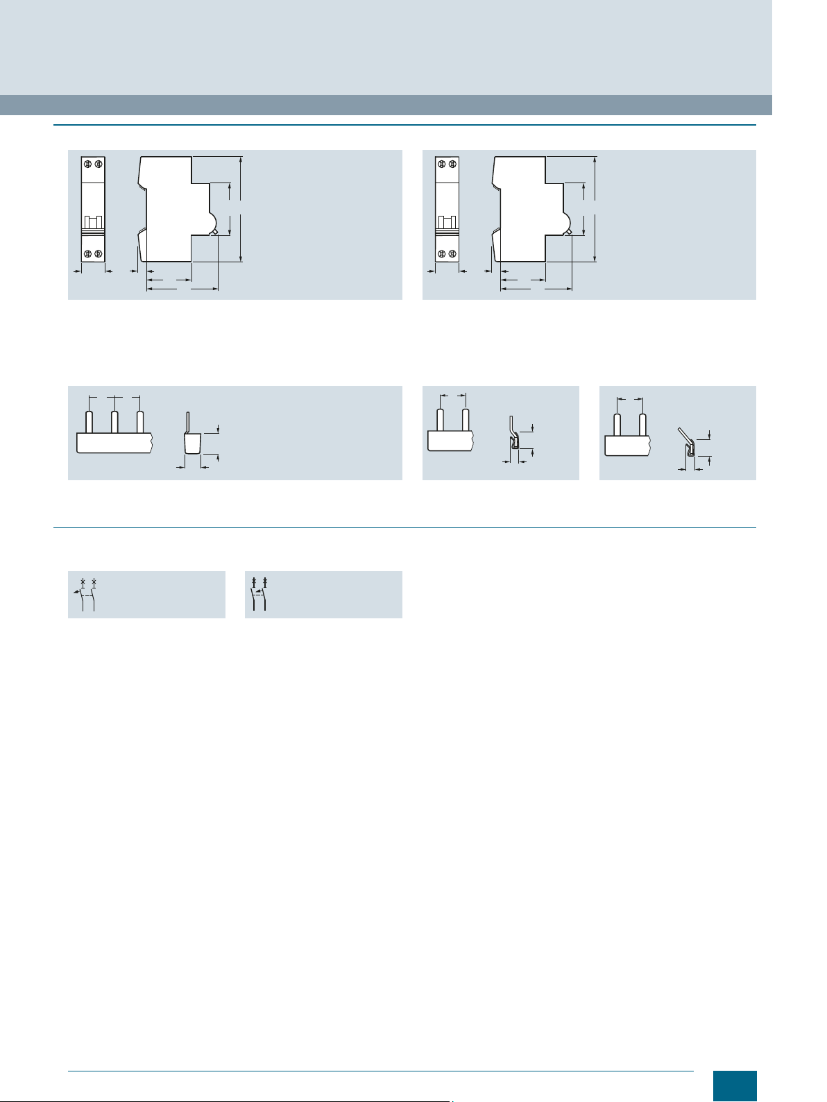
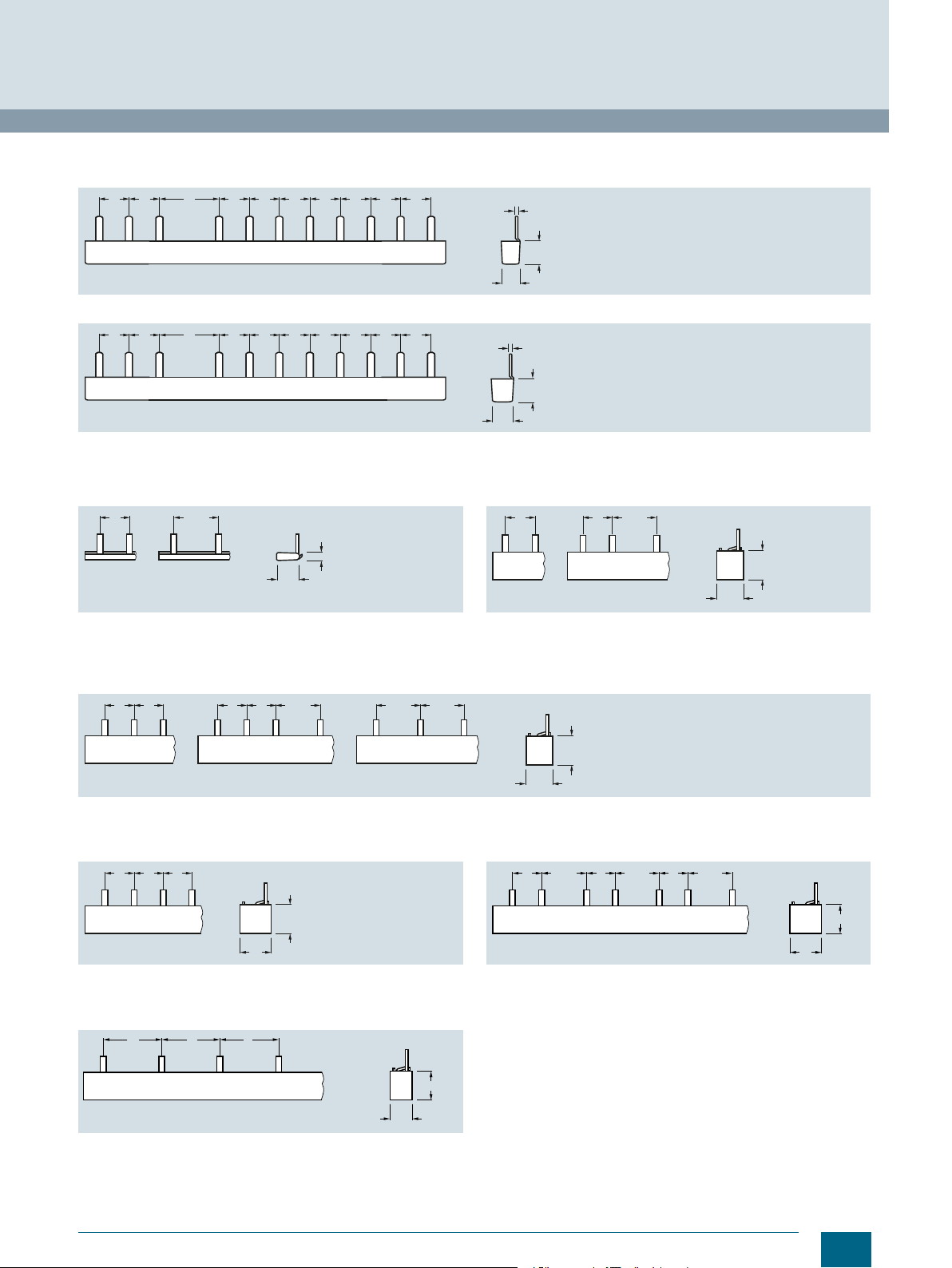
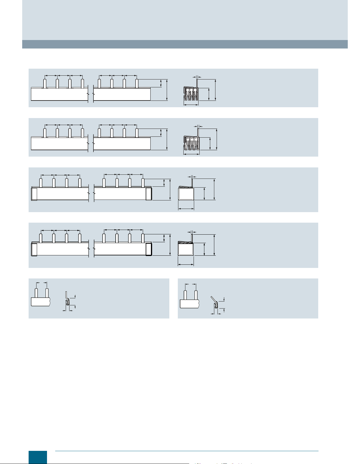
■
Dimensional drawings
5ST36
Pin spacing in MW (modular width; 1 MW = 18 mm)
Dimensions of side view in mm (approx.)
© Siemens AG 2016
5ST3600
5ST3630
5ST3606
5ST3607
5ST3608
5ST3613
5ST3614
5ST3615
5ST3667
5ST3601
5ST3602
5ST3631
5ST3632
5ST3616
5ST3617
5ST3603
5ST3633
5ST3604
5ST3605
5ST3634
5ST3635
5ST3618
5ST3620
5ST3636
5ST3637
5ST3638
5ST3640
5ST3641
5ST3642
5ST3643
5ST3644
5ST3645
5ST3668
5ST3621
5ST3622
5ST3651
5ST3652
18
5ST3646
5ST3647
5ST3623
5ST3653
Siemens · 10/2015
5ST3648
5ST3650
Page 21
5ST36
15,2
9,2
I201_13672
L1 L2 L3 L1 L2 L3 L1 L2 L3 L1 L2
111111211 1
1,5
I201_13673
L1 L2 L3 L1 L2 L3 L1 L2 L3 L1 L2
111111211 1
19
10,3
1,5
3,5
13
1,5
I201_13674
1
15
18
L1 L2 L3
11 1,5
L1 L2 L3
11
L1 L2 L3
1,5 1,5
I201_13677
L1 L2 L3 N
1 1 1
I201_13679
18
20
Pin spacing in MW (modular width; 1 MW = 18 mm)
Dimensions of side view in mm (approx.)
5ST3624
5ST3654
5ST37
Pin spacing in MW (modular width; 1 MW = 18 mm)
Dimensions of side view in mm (approx.)
© Siemens AG 2016
Miniature Circuit Breakers
Busbars
5ST standard busbars
1
1
1,5
5ST3700
5ST3701
5ST3730
5ST3731
5ST3702
5ST3703
5ST3732
5ST3733
L1 L2
5ST3704
5ST3705
5ST3734
5ST3735
L1 L2
5ST3706
5ST3707
5ST3736
5ST3737
Single-phase Single-phase Two-phase Two-phase
5ST3708
5ST3710
5ST3738
5ST3740
5ST3711
5ST3712
5ST3741
5ST3742
5ST3713
5ST3714
5ST3743
5ST3744
1 1,5 1,5 1,51 1
L1 N L2 N L3 N
5ST3715
5ST3716
5ST3745
5ST3746
5ST3746-2
I201_13675
15
18
I201_19174
17
20
2 2 2
L1 L2 L2L1
I201_19201
5ST3735-2
14
17
Siemens · 10/2015
19
Page 22
Miniature Circuit Breakers
N
N
N
N
N
N
N
N
L3
L2
L3
L2
L1
L1
L1
L1
I201_18187
1
N
N
N
N
N
N
N
N
L3
L2
L3
L2
L1
L1
L1
L1
I201_18188
1,5
1 1
1
1 1
1
11, 9
30,2
18,3
30,2
22,1
1
L1 L2 L2L3 L3NNN
I202_01456
11, 9
30,2
1 1
1
1 1
1
18,3
30,2
22,1
1,5
L1 L2 L2L3 L3NNN
I202_01458
10
5,6
I201_13680
1
Busbars
5ST standard busbars
5ST37
Pin spacing in MW (modular width; 1 MW = 18 mm)
Dimensions of side view in mm (approx.)
5ST3770-2
5ST3770-3
© Siemens AG 2016
5ST3770-4
5ST3770-5
5ST3762
5ST3764
1
5ST3763
5ST3765
I201_13681
10
5,6
20
Siemens · 10/2015
Page 23
S
I201_13755
© Siemens AG 2016
Miniature Circuit Breakers
5ST3 busbars acc. to UL 508
■
Overview
Products according to UL standards are used in North America,
but also in several other countries. This is important in particular
for exporting machines or electrical switchgear assemblies and
equipment to the USA. Acceptance and delivery are possible
only if the relevant UL standards are satisfied.
The 5ST37 busbar system according to UL 508 and CSA is
suitable for both universal use worldwide with all 5SY and 5SP
miniature circuit breakers for "Supplementary Protection"
certified according to UL 1077 and for 3NW and 3NC fuse
holders certified according to UL 512. Not approved for use in
feeder circuits.
■
Technical specifications
Standards
Approvals
Operational voltage
• Acc. to IEC V AC 690
• Acc. to UL 508 V AC
Rated conditional short-circuit current kA
• Dielectric strength kV/mm
• Surge strength kV
Max. current UL A
IEC A
Maximum busbar current I
• Infeed at the start of the busbar A 80 100 -- --
• Infeed at the center of the busbar A
Insulation coordination
• Overvoltage category III
• Pollution degree
Short-circuit current load capability
Busbar cross-section mm
Infeed
Conductor cross-sections Solid AWG
Ter mi nals ± screw (Pozidriv)
• Terminal tightening torque Nm
/phase
S
2
18 mm
2
25 mm
Stranded AWG
The busbars are available in single-, two- and three-phase
versions with different pin spacings and with two cross-sections
18 mm² and 25 mm². Infeed can be directly into the terminals of
the miniature circuit breaker or through connection terminals.
The connection terminals are available in two versions – for
direct infeed at the busbar or for infeed directly at the miniature
circuit breaker/fuse holder. Pins that are not required can be
covered with touch protection covers.
5ST37..-0HG 5ST37..-2HG 5ST3770-0HG 5ST3770-1HG
UL 508, CSA C22.2 No. 14-M 95 / IEC 60999
UL508 File No. E328403
CSA
600
10
25
> 9.5
-- -- 115
-- -- 160
160 200 -- --
2
10000 A RMS sym. 600 V for three circuits
100 000 A RMS sym. for protection with Class J 175 A
100 000 A RMS sym. for protection with Class J 200 A
2
Cu 18 25 -- --
Any
-- -- 10 ... 1/0 10 ... 1
2
mm
mm
lb/in
-- -- 6 ... 35 (Cu 60 °C) 6 ... 50 (Cu 75 °C)
-- -- 10 ... 2
2
-- -- 6 ... 35
-- -- 2 2
-- -- 5 3.5
-- -- 50 35
Busbars
Infeed at the start or end of the busbar Infeed along the busbar or midpoint infeed
321
S1
The sum of the outgoing current per branch (1, 2, 3...n) must not be greater
than the max. busbar current I
/phase.
S
1
S
Siemens · 10/2015
2 3
S2
I201_13754a
21
Page 24
Miniature Circuit Breakers
2
1
I202_02123
1,5
15
5
23
21
L1 L2 L3
11 1,5
L1 L2 L3
11
L1 L2 L3
1,5 1,5
I202_02122
1,5
2,5
I202_02104
1,5
15
5
23
21
L1 L2 L3
21,5 1,5
I202_02106
24
22 9,5
I202_02108
14
59,5
1
I202_02107
18,5
60
8
3
16
28,5
I202_02110
85,2
14 3,8
5,7
R 0,5
24
23,8
71,2
I202_02109
17,8
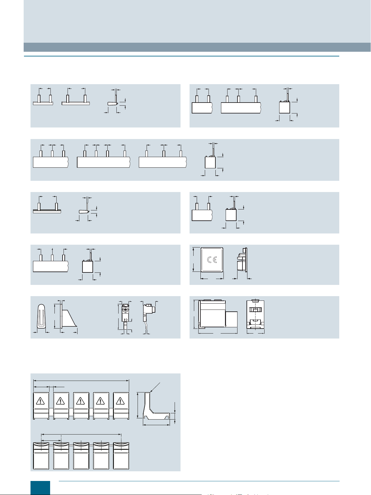
Busbars
5ST3 busbars acc. to UL 508
■
Dimensional drawings
5ST37 busbars
Pin spacing in MW (modular width; 1 MW = 18 mm)
Dimensions of side view in mm (approx.)
© Siemens AG 2016
1
1,51
1,5
L2L1
L2L1
5ST3701-0HG 5ST3703-0HG 5ST3705-0HG 5ST3707-0HG
5ST3710-0HG 5ST3712-0HG 5ST3714-0HG
1,5
L1 L2
2
I202_02105
23
21
5ST3701-2HG 5ST3705-2HG
5ST3710-2HG 5ST3750-0HG
I202_02124
23
21
5ST3748-0HG 5ST3770-0HG 5ST3770-1HG
5ST36 touch guard
Pin spacing in MW (modular width; 1 MW = 18 mm)
Dimensions of side view in mm (approx.)
5ST3655-0HG
22
Siemens · 10/2015
30
I202_02111
40
18
Page 25
© Siemens AG 2016
Miniature Circuit Breakers
5ST2 distribution blocks
■
Overview
Distribution blocks for standard rail mounting
Using distribution blocks it is possible to implement one, two,
three and four-phase systems with a rated current of up to 400 A.
This allows supply terminals to be divided into several load
circuits with different cable cross-sections.
■
Technical specifications
Standards,
certifications
Degree of protection
Poles
Approved cable
Conductor cross section
• Inputs per pole
- Solid/stranded conductor
acc. to IEC
- Flexible wire with sleeve
connector
• Outputs per pole
- Solid/stranded conductor
acc. to IEC
- Flexible wire with sleeve
connector
Tightening torque
• Inputs lb/in 13.5 13.5 3.5 ... 5
Plug-in connection
• Outputs Large lb/in
Plug-in connection
Operational voltage
• IEC, max. V 690 690 1000 V AC
Overcurrent protection
• Max. rated current A 80 125 175
• Rated peak withstand current (I
• Rated short-time withstand current (I
Block dimensions (D x H x W) mm
Neutral conductor mm²
Neutral conductor mm²
Neutral conductor Large mm²
Neutral conductor Large mm²
Plug-in connection
Small lb/in
)kA21.6 24 20
pk
1 s) kA 3 4.2 6.2
cw
mm² 1 x 2.5 … 16 1 x 6 … 35 1 x 10 … 35
mm²
Large mm² 8 x 1,5 … 10 2 x 4 … 16 3 x 6 … 25
Small mm²
Small mm²
Large mm²
Small
Small
Nm
Nm
Nm
The distribution blocks are made of thermoplastic with electrical
and mechanical components, which enables their use under
high thermal and mechanical load acc. to IEC 60947-7-1.
5ST2501 5ST2502 5ST2503
IEC 60947-7-1
IP 20
4
Copper
-- 1 x 6 … 35 -1 x 2.5 … 10 1 x 6 … 25 1 x 10 … 25
-- 1 x 6 … 25 --
-- 5 x 1,5 … 6 8 x 2.5 … 16
-- 6 x 4 … 16 --
-- 4 x 1,5 … 10 -8 x 1,5 … 10 2 x 4 … 10 3 x 6 … 16
-- 5 x 1,5 ... 6 8 x 2,5 ... 10
-- 6 x 4 … 10 --
-- 4 x 1,5 ... 6 --
1.5 1.5 2
PZ2 PZ2 PZ2
13.5 13.5 13.5
1.5 1.5 1.5
PZ1 PZ2 PZ2
-- 7.2 13.5
-- 0.8 1.5
-- PZ1 PZ2
88 x 49 x 85 75 x 45 x 98 102 x 47 x 87
Busbars
1500 V DC
Siemens · 10/2015
23
Page 26
© Siemens AG 2016
Miniature Circuit Breakers
Busbars
5ST2 distribution blocks
UL types
5ST2504 5ST2505 5ST2507 5ST2508 5ST2511
Standards,
certifications
Degree of protection
Poles
Approved cable
Wiring type
• Front/back
Conductor cross section
• Inputs
- Solid and stranded conductor
acc. to UL
- Solid and stranded acc. to IEC mm²
- Solid and stranded conductor
acc. to UL
- Solid and stranded acc. to IEC mm²
- Finely stranded with end sleeve
acc. to UL
- Finely stranded with end sleeve
acc. to IEC
- Finely stranded with end sleeve
acc. to UL
- Finely stranded with end sleeve
acc. to IEC
•Outputs
- Solid and stranded conductor
acc. to UL
- Solid and stranded acc. to IEC mm²
- Solid and stranded conductor
acc. to UL
- Solid and stranded acc. to IEC mm²
- Solid and stranded conductor
acc. to UL
- Solid and stranded acc. to IEC mm²
- Finely stranded with end sleeve
acc. to UL
- Finely stranded with end sleeve
acc. to IEC
- Finely stranded with end sleeve
acc. to UL
- Finely stranded with end sleeve
acc. to IEC
Tightening torque
• Inputs lb/in 13.2 ... 26.5 31 ... 44 44 ... 53 170 ... 186 222
Plug-in connection
• Outputs Large lb/in
Plug-in connection
Amperes per pole, max. (UL/IEC) A
Operational voltage
•UL, max. (AC) V 600
•IEC, max. (AC/DC) V
Overcurrent protection
• Required class J
• Max. rated current (UL/IEC) A
• SCCR RMS Sym A kA
• Rated peak withstand current (I
• Rated short-time withstand current (I
Clearance
• Air inches
• Creepage distance inches
Fire class
Block dimensions (D x H x W) mm
Connections
1)
Copper jumper is tested for a rated current of 100 A
)kA2.7 30 51
pk
Large AWG 1 x 14 … 4 1 x 8 … 2 1 x 8 … 2 / 0 1 x 2 … 4 / 0 1 x 3 /
Small AWG
Large AWG
mm²
Small AWG
mm²
To p A WG 4 x 14 … 10 6 x 14 … 6 6 x 14 … 6 4 x 16 … 8 --
Medium AWG
Bottom AWG
To p A WG
mm²
Bottom AWG
mm²
Nm
Plug-in connection
Small lb/in
1 s) kA 1.9 4.2 11 21
cw
Nm
Nm
(mm)
(mm)
UL 1059 / UL 486E / IEC 60947-7-1
UL File No. E80027 / XCFR2
C22.2 No. 158 -1987 / XCFR8
IP 20
1
Copper
Factory and field wiring
Pressure wire connector
2.5 ... 16 10 ... 35 10 ... 70 35 ... 120 95 … 185
-- 1 x 14 ... 6 --
-- 6 ... 16 --
1 x 14 … 4 1 x 8 … 2 1 x 8 … 1 1 x 2 … 3 / 0 3 / 0 … 5 / 0
2.5 ... 16 10 ... 35 10 ... 50 35 ... 95 95 … 150
-- 1 x 14 ... 6 --
-- 6 ... 16 --
2.5 ... 6 2.5 ... 16 2.5 ... 16 1.5 ... 10 --
-- 5 x 16 … 6
-- 1.5 ... 16
2 x 14 … 6 -- 2 x 14 … 2
2.5 ... 16 -- 2 x 2.5 … 35
4 x 14 … 10 6 x 14 … 6 6 x 14 … 6 2 x 14 … 4
2.5 ... 6 2.5 ... 16 2.5 ... 16 2 x 2,5 ... 25
2 x 14 … 6 -- 2 x 14 … 4 --
2.5 ... 16 -- 2 x 2.5 … 25
1.5 ... 3 3.5 ... 5 5 ... 6 19 ... 21 25
13.2 ... 26.5 17.7 ... 26.5 13.2 ... 26.5 31 ... 62
1.5 ... 3 2 ... 3 1.5 ... 3 3.5 ... 7
PZ2 Standard screwdriver
7 ... 13.2 -- 18 ... 27
0.8 ... 1.5 -- 2 ... 3
PZ1 -- Standard screwdriver
80/80 115/125 160/160 230/250 310/400
1000/1500
80/80 115/125 160/160 230/250 310/400
100
3 / 8 (9.5)
1 / 2 (12.7)
UL 94V-0
66 x 47 x 27 74 x 47 x 27 92 x 49 x 35 96 x 49 x 45 96 x 49 x 45
With cable up to
16 mm²
Allen key (4 mm) Allen key (5 mm) Allen key (6 mm) Allen key (8 mm)
With connector or
cable up to
1)
16 mm²
Lateral incoming
feeder for parallel
connection with
copper bar
(max. 16 x 5 mm)
UL 1059 / UL 486E / IEC 60947-7-1
UL File No. E80027 / XCFR2
-- --
0 … 350 MCM
--
24
Siemens · 10/2015
Page 27
I201_18405
434
66
27
I201_18406
434
74
27
I201_18407
445
92
35
I201_18409
445
96
45
495
88
85
I201_18402
I201_18403
41
5
75
98
I201_18404
50
87
162
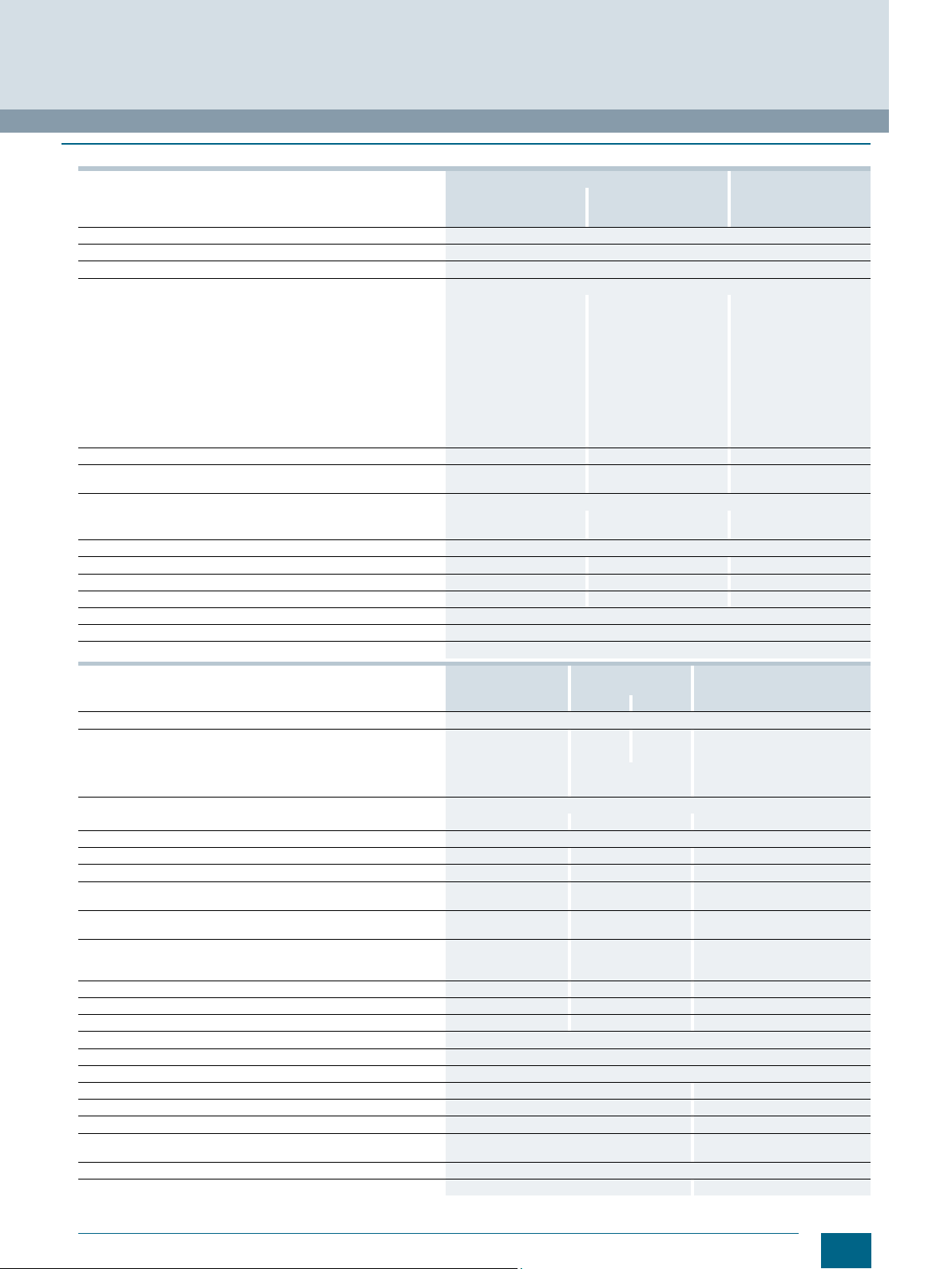
© Siemens AG 2016
■
Dimensional drawings
5ST2504 5ST2505
Miniature Circuit Breakers
Busbars
5ST2 distribution blocks
96
5ST2507 5ST2508
45
I201_18408
445
5ST2511 5ST2501
5ST2502 5ST2503
Siemens · 10/2015
25
Page 28
© Siemens AG 2016
Miniature Circuit Breakers
Busbars
SIKclip wiring system
■
Overview
SIKclip is a fast wiring system that simplifies the connection of
control switches:
• For mounting directly on the rear vertical CU busbar system
• Mounting via brackets on the rear of the DIN rail
The 4-pole busbar can handle loads of up to 250 A, each
individual contact up to 63 A.
High degree of protection because each contact is locked
individually.
■
Technical specifications
Compliance to standards EN 60947-1, EN 61439-1
Degree of protection
Max. rated current I
Max. rated output current I
Rated operational voltage U
Rated insulation voltage V AC
Test voltage kV
Connecting cables
Connecting cable type
Ambient temperature °C
n
n
n
A 250 at 40 °C ambient temperature
A 63 A at 40 °C ambient temperature
V AC 400
SIKclip is made of thermoplastic acc. to IEC 60439-3 and is
suitable for high thermal loads.
Note:
To install the SIKclip wiring system in the ALPHA AS, the busbars
must be installed in a vertical rear position, but not recessed. If
the busbars are in a recessed position the cables will not reach
the circuit breakers.
5ST25..
IP20
660
2.5, 50 Hz
40 A (6 mm2), 63 A (10 mm2)
H07VK
-5 ... +60
26
Siemens · 10/2015
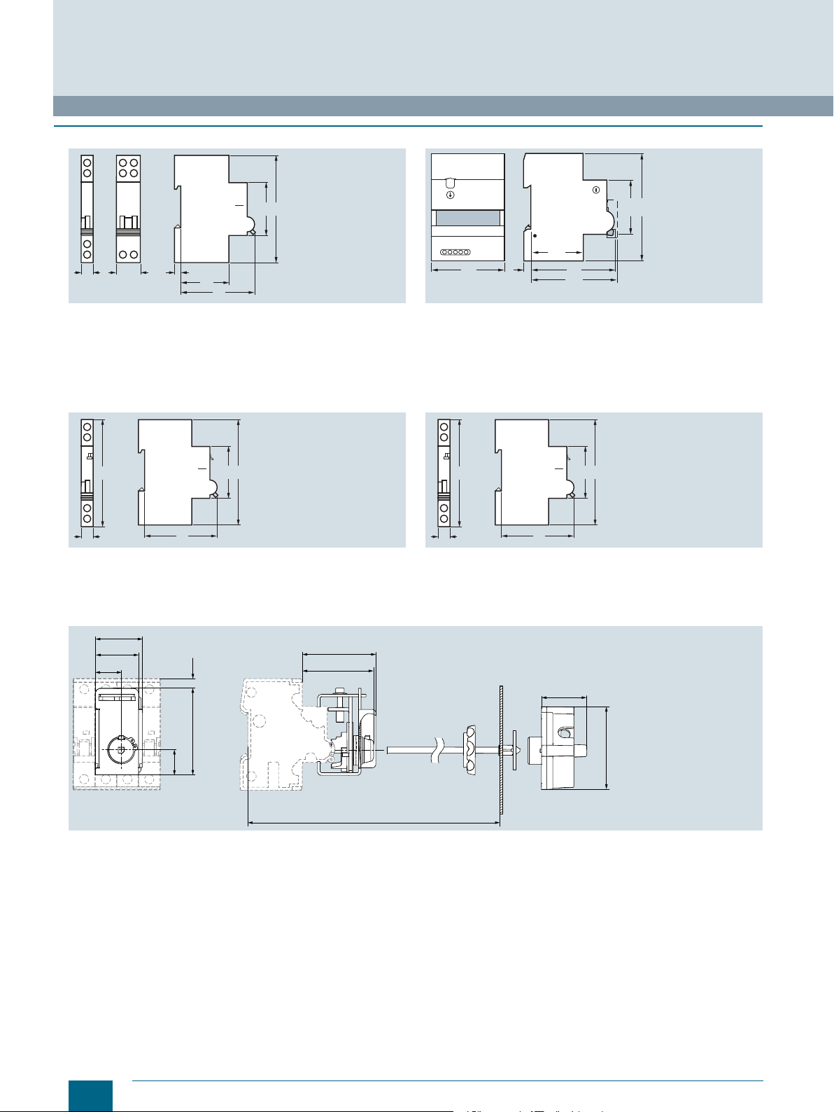
Page 29
■
436,5
50
L1
647,5
L2 L3 N Ø8,5
25 25 50
50
17
12,5
65
29,8 (N)
40,3 (L3)
50,8 (L2)
58,3 (L1)
L1 L2 L3 N Ø8,5
I201_18489
25 25 50
F
F
mounting bracket
mounting bracket
transparent protective cover
(40 x 16 x 252)
transparent protective cover
(40 x 16 x 252)
Dimensional drawings
© Siemens AG 2016
Miniature Circuit Breakers
Busbars
SIKclip wiring system
Siemens · 10/2015
27
Page 30
6 000
10 000
15 000
© Siemens AG 2016
Miniature Circuit Breakers
Configuration and dimensioning
■
Overview
Breaking capacity
Particular demands are made on miniature circuit breakers with
regard to breaking capacity.
The values are standardized and are determined according to
the test conditions of IEC/EN 60898-1/-2 or DIN VDE 0641-11.
The values of the rated breaking capacity I
.
and
are ,
cn
5SL3, 5SL4, 5SL6, 5SY6, 5SY4, 5SY7, 5SY8, 5SY60 and 5SP4 miniature circuit breakers
IEC/EN 60898-1 IEC/EN 60947-2
1-pole, 1-pole+N 2-, 3-, 4-pole, 3-pole+N 1-pole, 1-pole+N 2-, 3-, 4-pole, 3-pole+N
230 V AC AC 400 V 230 V AC AC 400 V
[A] I
I
5SL3 0.3 ... 63
5SL4 0.3 ... 63
5SL6 0.3 ... 63
5SY6 (without 5SY60) 0.3 ... 6
5SY4 0.3 ... 6
5SY7 0.3 ... 2
5SY8 0.3 ... 2 -- 70
5SY30.. 2 ... 40 4.5 -- --
5SY60.. 2 ... 40
5SP4 80 ... 125
1)
D50 and D63: Icu = 15 kA.
2)
D50 and D63: Icu = 20 kA.
n
8 ... 32
40 ... 63
8 ... 32
40 ... 63
80
3 ... 6
8 ... 10
13 ... 32
40 ... 63
3 ... 6
8 ... 10
13 ... 32
40 ... 63
[kA] I
cn
4.5 --
10 10
6 6
6 30
6 15
6 10
10 35
10 20
10 15
10 10
15 50
15 40
15 30
15 25
15 20
-- 50
-- 40
-- 30
-- 25
6 -- 6 --
10 10
For other test conditions, it is also possible to specify values
higher than those stipulated in IEC/EN 60898-1/-2 or
DIN VDE 0641-11.
One such standard is IEC/EN 60947-2 or DIN VDE 0660-101 for
circuit breakers.
[kA] I
cn
[kA] I
cu
1)
2)
[kA]
cu
5SY5 miniature circuit breakers
Miniature circuit breakers,
universal current
[A] I
I
5SY5 0.3 ... 63
n
IEC/EN 60898-2 IEC/EN 60898-2
1-pole 2-pole 1-pole 2-pole
230/400 V AC AC 400 V 220 V DC 440 V DC
[kA] I
cn
10 10
5SY30.. and 5SY60.. miniature circuit breakers.
Rated making and
breaking capacity I
5SY30.. 2 ... 16 4.5
5SY60.. 2 ... 4
28
cn1
In [A] I
20 ... 40 3
6 ... 16
Siemens · 10/2015
IEC/EN 60898-1
1-pole + N
230 V AC
[kA]
cn1
6
4.5
[kA] I
cn
[kA] I
cn
[kA]
cn
Page 31

30
I201_13651
201510865432
1
2
4
10
20
40
2
1
4
10
20
40
6
60
120
1
6
Multiple of rated current
Tripping time
MinutesSeconds
1.5
1.451.13
0.01
0.02
0.04
0.1
0.2
0.4
0.06
0.6
30
I201_13652
201510865432
1
2
4
10
20
40
2
1
4
10
20
40
6
60
120
1
6
Multiple of rated current
Tripping time
MinutesSeconds
1.5
1.451.13
0.01
0.02
0.04
0.1
0.2
0.4
0.06
0.6
© Siemens AG 2016
■
Characteristic curves
Tripping characteristics acc. to IEC/EN 60898-1, DIN VDE 0641-11
Tripping characteristic A
For limited semiconductor protection, protection of measuring
circuits with transformers. Protection of circuits with tripping in
0.4 s acc. to DIN VDE 0100-410, for long cable lengths.
Miniature Circuit Breakers
Configuration and dimensioning
1.451.13
120
60
40
20
10
6
MinutesSeconds
Tripping time
4
2
1
40
20
10
6
4
2
1
0.6
0.4
0.2
0.1
0.06
0.04
0.02
0.01
1.5
1
Multiple of rated current
Tripping characteristic B
MCBs with this tripping characteristic are designed for universal
use in socket outlet and lighting circuits. Proof of personal safety
acc. to DIN VDE 0100-410 is not required.
I201_13653
201510865432
30
Tripping characteristic C
In lamp and motor circuits with higher starting currents, MCBs
with tripping characteristic C are generally used.
1.451.13
120
60
40
20
10
6
MinutesSeconds
Tripping time
4
2
1
40
20
10
6
4
2
1
0.6
0.4
0.2
0.1
0.06
0.04
0.02
0.01
1
1.5
Multiple of rated current
I201_13654
201510865432
30
Tripping characteristic D
For electrical circuits with strong pulse-generating equipment,
such as transformers or solenoid valves.
Siemens · 10/2015
29
Page 32

Miniature Circuit Breakers
I201_13659
-20 -10 0 2010 4030 50
Curve 1
Curve 2
Curve 3
Ambient Temperature [°C]
Correction Factor
0.8
0.9
1.0
1.1
1.2
1.3
Configuration and dimensioning
Tripping characteristics
Tripping behaviour at 30 °C ambient temperature
Tripping
characteristic
A --
B IEC/EN 60898-1, 1.13 × I
C IEC/EN 60898-1, 1.13 × I
D IEC/EN 60898-1, 1.13 × I
Standards Thermal release Electromagnetic release
Test currents: Test currents:
Small Large Tripping time Hold Latest Tripping time
test current test current In ≤ 63 A In > 63 A tripping
I
1
1.13 × I
n
n
DIN VDE 0641-11
DIN VDE 0641-11
n
DIN VDE 0641-11
n
© Siemens AG 2016
I
2
1.45 × I
n
1.45 × I
n
1.45 × I
n
1.45 × I
n
t t I
4
> 1 h > 2 h 2 × I
n
I
5
< 1 < 2 3 × I
> 1 h > 2 h 3 × I
n
< 1 < 2 5 × I
> 1 h > 2 h 5 × I
n
< 1 < 2 10 × I
> 1 h > 2 h 10 × I
n
< 1 < 2 20 × I
(IEC 60898: 50 × In)
t
≥ 0.1 s
n
< 0.1 s
≥ 0.1 s
n
< 0.1 s
≥ 0.1 s
n
< 0.1 s
≥ 0.1 s
n
< 0.1 s
Correction factors for the rated current at different ambient
temperatures for
5SL3...-. and 5SL6...-.
Dependence of the permissible continuous load current on the
ambient temperature for 5SL3...-. and 5SL6...-. miniature circuit
breakers
The valid curve for the correction factor can be found in the
following table.
Curve for correction factor for 5SL3...-. and 5SL6...-. miniature circuit breakers
Rated current (A) 0.3 0.5 1 1.6 2 3 4 6 8 10 13 16 20 25 32 40 50 63
Characteristic Pole type
B 1P/2P
C 1P/2P
3P/4P
3P/4P
Correction factors for the rated current at different ambient
temperatures for
5SL4…-.
Dependence of the permissible continuous load current on the
ambient temperature for 5SL4...-. miniature circuit breakers
1,3
1,2
1,1
Correction Factor
1,0
0,9
0,8
-20 -10 0 2010 4030 50
Ambient Temperature [°C]
(for curves, see diagram above)
Valid curve for the correction factor for 5SL miniature circuit breakers
-- -- -- -- -- -- -- 3 -- 2 2 2 3 3 3 3 3 3
-- -- -- -- -- -- -- 3 -- 2 2 2 3 2 1 2 3 3
3 3 2 2 2 3 3 3 2 3 2 2 3 3 3 3 3 3
2 2 2 1 2 2 2 3 2 3 2 2 3 2 3 2 3 3
Curve 1
Curve 2
Curve 3
I201_18164
30
Siemens · 10/2015
Page 33

I201_13659
-20 -10 0 2010 4030 50
Curve 1
Curve 2
Curve 3
Ambient Temperature [°C]
Correction Factor
0.8
0.9
1.0
1.1
1.2
1.3
© Siemens AG 2016
Correction factors for the rated current at different ambient temperatures for 5SY
Dependence of the permissible continuous load current on the
ambient temperature for 5SY miniature circuit breakers
Dependence of the permissible continuous load current on the
ambient temperature for 5SY60. . miniature circuit breakers
(without 5SY60..)
1.3
1.2
1.1
Correction Factor
Miniature Circuit Breakers
Configuration and dimensioning
I201_18160
1.0
0.9
0.8
-20 -10 0 2010 4030 50
Ambient Temperature [°C]
The valid curve for the correction factor can be found in the
following table.
Curve for correction factor for 5SY miniature circuit breakers
Rated current (A) 0.3 0.5 1 1.6 2 3 4 6 8 10 13 16 20 25 32 40 50 63 80
Characteristic Pole type
A 1P/2P
B 1P/2P
C 1P/2P
D 1P/2P
3P/4P
3P/4P
3P/4P
3P/4P
3 3 2 2 2 3 3 3 2 3 2 2 3 2 2 3 2 3 -2 2 2 1 2 2 2 2 2 2 1 1 2 1 1 1 1 2 --
-- -- -- -- -- -- -- 3 -- 3 2 2 3 3 2 3 2 3 2
-- -- -- -- -- -- -- 2 -- 2 1 2 2 1 1 1 1 2 1
3 3 2 2 2 3 3 3 3 3 2 3 3 2 2 3 2 3 2
2 2 2 1 2 2 2 2 3 3 2 2 2 2 1 1 1 2 1
3 3 2 2 2 3 3 3 3 3 2 3 3 2 2 3 2 3 -2 2 2 1 2 2 2 2 3 3 2 2 2 2 2 2 1 2 --
Valid curve for the correction factor for 5SY miniature circuit breakers
Curve for correction factor for 5SY60.. miniature circuit breakers
Rated current (A) 2 4 6 8 10 13 16 20 25 32 40
Characteristic
B
C
-- -- 1 -- 2 2 2 2 1 2 2
-- -- 1 3 2 2 3 3 1 2 2
Valid curve for the correction factor for 5SY60.. miniature circuit breakers
The valid curve for the correction factor can be found in the
following table.
(for curves, see left-hand diagram above)
(for curves, see right-hand diagram above)
Curve 1
Curve 2
Curve 3
Siemens · 10/2015
31
Page 34

0,8
0,9
1,0
1,1
1,2
1,3
-20 -10 0 2010 4030 50
Curve 1
Curve 2
Curve 3
Ambient Temperature [°C]
Correction Factor
I201_18164
© Siemens AG 2016
Miniature Circuit Breakers
Configuration and dimensioning
Correction factors for rated current if bundling
If more than one electrical circuit is loaded in a series of
miniature circuit breakers the resulting increase in ambient
temperature affects the characteristic curve. In this case an
additional correction factor, specific to the rated current of the
miniature circuit breaker, must be taken into account.
Number of MCBs 1 2 ... 3 4 ... 6 > 7
Correction factor K
Correction factors for rated current at different frequencies
The tripping characteristic applies to a frequency of 50 Hz to
60 Hz. In the case of other frequencies, the following correction
factors must be taken into account.
In the overrange, the limits of the characteristic curves
correspond to the correction factors of the thermal tripping
operation. In the event of a short-circuit, the limits of the
characteristic curves correspond to the correction factors of the
magnetic tripping operation.
1.00 0.90 0.88 0.85
Correction factors for rated breaking capacities
on altitude above sea level of location
Altitude
above sea
level / m
500
1000
1500
2000
2500
3000
3500
4000
Correction
factor
1 6 10 15 10
1 6 10 15 10
1 6 10 15 10
1 6 10 15 10
0.94 5.6 9.4 14.1 9.4
0.88 5.3 8.8 13.2 8.8
0.83 5 8.3 12.4 8.3
0.78 4.7 7.8 11.7 7.8
Icn / kA
5SY6
Icn / kA
5SY4
Icn / kA
5SY7
Icn dependent
Icn / kA
5SP4
Thermal tripping operation
Rated current In (A) Correction factor for
0 Hz 16 2/3 Hz 50/60 Hz 125 Hz 400 Hz 1000 Hz
5SL4...-. 0.3 ... 6
5SY 0.3 ... 10
5SP 80 ... 125
8 ... 20
25 ... 40
50 ... 63
1 ... 40
50 ... 63
1 1 1 1 1 1
1 1 1 1 0.99 0.98
1 1 1 1 0.99 0.96
1 1 1 0.99 0.96 0.92
1 1 1 1 0.99 0.97
1 1 1 0.98 0.97 0.93
1 1 1 0.98 0.94 0.86
1 1 1 0.97 0.92 0.85
Magnetic tripping operation
Rated current In (A) Correction factor for
0 Hz 16 2/3 Hz 50/60 Hz 125 Hz 400 Hz 1000 Hz
5SL4...-. B1 ... B63
5SY 0.3 ... 63
5SP 80 ... 125
C0.3 ... C63
D0.3 ... D63
-- 1.2 1 1.3 1.6 2.0
-- 1.2 1 1.2 1.5 1.9
-- 1.1 1 1.2 1.5 1.8
1.4 1 1 1.2 1.4 1.7
1.5 1 1 1.05 1.3 1.8
Dependence of the reduction factor on the ambient temperature for 5SP miniature circuit breakers
Curve for correction factor for 5SP4 miniature circuit breakers
(for curves, see diagram on the left)
Rated current (A) 80 100 125
Characteristic
C 1P 2 2 2
2P/3P/4P 1 1 1
D 1P 2 3 --
2P/3P/4P 1 1 --
32
Siemens · 10/2015
Page 35

Let-through current I
max
B40
B6
B16
B32
B50/63
B20/25
B10/13
p
5000
4000
3000
2000
1000
0
0 1000 2000 3000 4000 5000 70006000
Let-Through Current
Prospective Short-Circuit Current
I201_19203
8000
7000
6000
5000
4000
3000
2000
1000
0
0
p
24681012
C0,3
C0,5
C1
C2
C3
C4
C6
C32
C40
C50/63
C8/10
C13/16
C20/25
C1,6
max
Let-Through Current
Prospective Short-Circuit Current
I201_19083
max
B40
B6
B16
B32
B50/63
B20/25
B10/13
p
5000
4000
3000
2000
1000
0
0 1000 2000 3000 4000 5000 70006000
Let-Through Current
Prospective Short-Circuit Current
I201_19086
5SL3...-6
max
© Siemens AG 2016
Let-through current I
8000
Miniature Circuit Breakers
Configuration and dimensioning
5SL4...-6
max
Let-through current I
5SL4...-7
max
7000
max
6000
B63
B50
B32/40
5000
4000
Let-Through Current
3000
2000
B25
B20
B16
B13
B10
B8
B6
B4
B3
1000
0
024681012
Prospective Short-Circuit Current
Let-through current I
8000
7000
max
6000
5000
4000
Let-Through Current
3000
2000
5SL4...-8
max
B2
B1
p
D50/63
D40
D20/25/32
D13/16
D8/10
D6
D4
D3
D2
D1,6
D1
1000
D0,5
0
024681012
Prospective Short-Circuit Current
D0,3
p
I201_19084
I201_19082
Let-through current I
5SL6...-6
max
Let-through current I
5000
max
4000
3000
Let-Through Current
2000
1000
0
0 1000 2000 3000 4000 5000 70006000
5SL6...-7
max
Prospective Short-Circuit Current
Siemens · 10/2015
C50/63
C32/40
C20/25
C16
C10/13
C8
C6
C3/4
C2
C1,6
C1
C0,5
C0,3
p
I201_19085
33
Page 36

Miniature Circuit Breakers
10
2
10
2
10
3
10
4
10
3
2
4
6
10
4
2
4
6
10
5
2
4
6
2468 8246
p
I201_18375
22
S
t
B50/63
B25/32/40
B20
B6
B10/13/16
Prospective Short-Circuit Current
Peak Let-Through Current
22
S
t
p
100
10
1
8
6
10
2
10
3
10
4
4
2
8
6
4
2
8
6
4
2
8
6
4
2
8
6
4
2
2
10
5
10
3
10
4
224667 9588
C0,5
C1
C1,6
C2
C3
C4
C6
C8/10
C13/16
C20/25
C50/63
C32/40
C0,3
Let-Through Current
Prospective Short-Circuit Current
I201_19088
Configuration and dimensioning
Let-through I2t values 5SL3 (AC)
Characteristic B
© Siemens AG 2016
Characteristic C
5
10
6
4
2
4
10
6
S
4
t
22
2
3
10
6
4
2
Peak Let-Through Current
2
10
6
4
2
1
10
C25/32/40/50/63
C16/20
C8/10/13
C6
C3/4
C2
I201_18376
C1,6
C1
C0,5
C0,3
2
10
2468 8246
3
10
Prospective Short-Circuit Current
p
4
10
Let-through I2t values 5SL4...-6 (AC)
Characteristic B
10
S
t
22
10
Let-Through Current
10
102
34
5
8
6
4
2
4
8
6
4
2
3
8
6
4
2
3
10
10
22466588
Prospective Short-Circuit Current
Siemens · 10/2015
B63
B50
B32/40
B25
B20
B16
B13
B10
B8
B6
B4
B3
B2
B1
4
p
Let-through I2t values 5SL4...-7 (AC)
Characteristic C
I201_19087
Page 37

Let-through I2t values 5SL4...-8 (AC)
22
S
t
D0,5
D1
D1,6
D2
D3
D4
D6
D8/10
D13/16
D20/25
D50/63
D32/40
D0,3
p
Let-Through Current
Prospective Short-Circuit Current
10
0
10
3
10
1
10
4
8
6
10
2
10
3
10
4
4
2
8
6
4
2
8
6
4
2
8
6
4
2
8
6
4
2
2
10
5
224667 9588
I201_19089
210
2
648103264810
p
[A]
2
10
2
4
6
8
3
10
2
4
10
4
6
8
2
5
10
4
6
8
[A s]
2
2
I201_18186
50/63
25/32/40
20
10/13/16
6
4
[A s]
2
210
2
648103264810
p
[A]
1
10
2
4
6
8
2
10
2
3
10
4
6
8
2
4
10
4
6
8
2
5
10
4
6
8
2
I201_18185
25/32/40/50/63
16/20
8/10/13
6
3/4
2
1,6
1
0,5
0,3
4
Characteristic D
© Siemens AG 2016
Miniature Circuit Breakers
Configuration and dimensioning
Let-through I2t values 5SL6 (AC)
Characteristic B Characteristic C
Siemens · 10/2015
35
Page 38

24610
p
[kA]
2
[kA s]
10
2
I201_10761
50/63 A
25/32/40 A
13/16/20 A
10 A
6 A
-1
2468
10
01
8
24610
2
8
10
-1
2
4
6
10
0
2
4
6
10
1
2
4
6
10
2
© Siemens AG 2016
Miniature Circuit Breakers
Configuration and dimensioning
Let-through I2t values 5SY6 (AC)
Characteristic B Characteristic C
2
10
6
4
2
[kA s]
2
2
1
10
6
4
2
0
10
6
4
2
-1
10
6
4
2
-2
10
4
6810-12
4
6810
50/63 A
20/25/32/40 A
13/16 A
8/10 A
6 A
I201_10762
3/4 A
2 A
1,6 A
1 A
0,5 A
0,3 A
0
2
1
4
61010-22
82461028
[kA]
p
36
Siemens · 10/2015
Page 39

Let-through I2t values 5SY4 (AC)
2
p
[kA]
2
[kA s]
2
4
610
I201_10764
1 A
10
63 A
10 A
1,6 A
2 A
3 A
4 A
6/8 A
32/40/50 A
13/16/20/25 A
-2
2
4
6810-12
4
6810
0
1
82461028
10
-2
2
4
6
10
-1
2
4
6
10
0
2
4
6
10
1
2
4
6
10
2
Prospective Short-Circuit Current
Let-Through Current
-2 2
8
6
4
28
10
108642-110864210 1010
6
4
2
6
4
2
6
4
2
6
4
2
2
10
1
10
0
10
-1
10
-2
10
6
4
2
I2_10766a
[kA]
p
22
[kA s]
0,3 A
0,5 A
1,6 A
2 A
3/4 A
6 A
8/10 A
13/16 A
1 A
50/63 A
80 A
20/25/32/40 A
Characteristic A
© Siemens AG 2016
Characteristic B
2
10
6
s
4
t k
2
22
1
10
6
4
2
Let-Through Current
0
10
6
4
2
10
6
4
2
10
Miniature Circuit Breakers
Configuration and dimensioning
-1
-2
-1
10
2468 8
0
10
2
Prospective Short-Circuit Current
4426
B80
B50/63
B25/32/40
B13/16/20
B10
B6
B4
B2
1
10
p
I201_18538a
k
Characteristic C
Characteristic D
3
10
6
4
2
[kA s]
2
2
2
10
6
4
2
1
10
Let-Through Current
6
4
2
0
10
6
4
2
-1
10
6
4
2
-2
10
-2
10 2 4 6
01
810-1246810
Prospective Short-Circuit Current
2
Siemens · 10/2015
40/50/63 A
32 A
25 A
20 A
16 A
8/10/13 A
6 A
4 A
3 A
2 A
1,6 A
1 A
0,5 A
0,3 A
4
610 10
82468
[kA]
p
I201_10767
2
37
Page 40

I201_16016a
10
0
10
1
468 2 468
10
1
10
2
10
3
2
4
6
2
4
6
100/125 A
80 A
I2_13
I2t [kA2s]
100 101468 2 468
101
10
103
2
4
6
2
4
6
80 A
100/125 A
I2_13684
Ip [kA]
I
2
t [kA
2
s]
10
0
10
1
468 2 468
10
1
10
2
10
3
2
4
6
2
4
6
80 A
100 A
© Siemens AG 2016
Miniature Circuit Breakers
Configuration and dimensioning
Let-through I2t values 5SP4 (AC)
Characteristic B Characteristic C
Characteristic D
38
Siemens · 10/2015
Page 41

20/
A
[kA]
[k
p
[kA]
2
[kA s]
2
I2_10774
2 A
3/4 A
1,6 A
1 A
0,5 A
0,3 A
24610
10
-1
24
68
10
0
8
1
24610
8
2
10
-2
2
4
6
10
-1
2
4
6
10
0
2
4
6
10
1
2
4
6
10
2
10 A
8 A
6 A
63 A
50 A
40 A
25/32 A
13/16 A
2
p
[kA]
2
[kA s]
2
610
I2_10771
10 4
0,3 A
13/16 A
20/25/32 A
50/63 A
8/10 A
6 A
1,6 A
0,5 A
1 A
3/4 A
2 A
40 A
-2
26410
-1
82 6410
0
8
1
82 6104282 610438
10
-2
2
4
6
10
-1
2
4
6
10
0
2
4
6
10
1
2
4
6
10
2
2
4
6
10
3
© Siemens AG 2016
Let-through I2t values 5SY5 (DC)
Characteristic B Characteristic C
Miniature Circuit Breakers
Configuration and dimensioning
Let-through I2t values 5SY8 (AC)
Characteristic C Characteristic D
3
10
6
4
2
[kA s]
2
2
2
10
6
4
2
1
10
6
50/63 A
40 A
32 A
25 A
20 A
13/16 A
8/10 A
I2_10772
6 A
4 A
3 A
2 A
1,6 A
1 A
4
2
10
0,5 A
0
6
4
2
-1
10
0,3 A
6
4
2
-2
10
-2
10 4
26410
-1
2
8
0
26
6410
8
1
10
82 6104282 610438
[kA]
p
Siemens · 10/2015
39
Page 42

Miniature Circuit Breakers
p
[kA]
2
[kA s]
2
2
I2_10769
2 A
3/4 A
6 A
20/25/32/40 A
1 A
1,6 A
0,5 A
0,3 A
8/10 A
13/16 A
50/63 A
261010 4
-2
2
6410
-1
82 6410
0
8
1
82 610428
10
-2
4
6
2
10
-1
4
6
2
10
0
4
6
2
10
1
4
6
10
2
p
[kA]
2
[kA s]
2
I2_10770
16 A
20 A
0,3 A
25 A
32 A
40/50/63 A
8/10/13 A
6 A
1,6 A
0,5 A
3 A
1 A
4 A
2 A
261010 4
-2
2
6410
-1
82 6410
0
8
1
82 610428
10
-2
2
4
6
10
2
4
6
-1
10
2
4
6
0
10
2
4
6
1
10
2
4
6
2
10
3
Configuration and dimensioning
Let-through I2t values 5SY7 (AC)
Characteristic B
2
10
6
4
2
[kA s]
2
2
1
10
6
4
2
0
10
6
4
2
-1
10
-1
10
2468
0
10 2 4
50/63 A
6
8
10
25/32/40 A
13/16/20 A
10 A
6 A
1
24
© Siemens AG 2016
68
10
[kA]
p
Characteristic D
I2_10768
2
Characteristic C
40
Siemens · 10/2015
Page 43

0,1
0,1 1 10
1
10
100
p
I201_18378
B10/13/16
22
S
t
B20
Let-through current
Prospective current
in kA
in
kA
2
s
2
Prospective Short-circuit Current
6
4
2
846
2
846
2
6
4
2
6
4
2
846
2
I201_18494
B40
B32
B20/25
B13/16
B10
B6
10
4
10
5
10
3
10
2
10
1
10
2
10
3
10
4
2
s
2
10
1
Prospective Short-circuit Current
6
4
2
846
2
846
2
6
4
2
6
4
2
846
2
I201_18495
C2
C4
C6/8
C10/13
C16/20
C25/32/
40
10
4
10
5
10
3
10
2
10
2
10
3
10
4
© Siemens AG 2016
Let-through I2t values 5SJ6...- . KS (AC)
Characteristic B Characteristic C
100
S
2
in kA
t
2
10
Let-through current
1
Miniature Circuit Breakers
Configuration and dimensioning
C16/20
C10/13
I201_18377
0,1
Let-through I2t values 5SY30 (AC)
Characteristic B Characteristic C
Prospective current
kA
in
p
1010,1
Siemens · 10/2015
41
Page 44

I201_13746b
10
2
10
1
10
0
10
-1
32 A
20/25 A
13/ 16 A
10 A
6 A
p [kA]
2
t [kA2s]
10
-1
10
0
10
1
2468 2468
2
4
6
8
2
4
6
8
2
4
6
8
40 A
10
2
10
1
10
0
10
-1
25/32/
40 A
16/
20 A
10/
13 A
4 A
6 A
Ip [kA]
I
2
t [kA
2
s]
10
-1
10
0
10
1
2468 2468
2
4
6
8
2
4
6
8
2
4
6
8
2 A
I201_13747a
© Siemens AG 2016
Miniature Circuit Breakers
Configuration and dimensioning
Let-through I2t values 5SY60 (AC)
Characteristic B Characteristic C
42
Siemens · 10/2015
Page 45

© Siemens AG 2016
Miniature Circuit Breakers
Configuration and dimensioning
Selectivity of miniature circuit breakers/fuses
Distribution systems are usually set up as radial networks. An
overcurrent protection device is required for each reduction of
the conductor cross-section. This produces a series connection
staggered according to rated currents, which should, if possible,
be "selective".
Selectivity means that, in the event of a fault, only the protective
device that is directly next to the fault in the current circuit is
tripped. This means that current paths in parallel can maintain a
power flow.
In the case of miniature circuit breakers with upstream fuses, the
selectivity limit depends largely on the current limitation and
tripping characteristics of the miniature circuit breaker and the
melting I
2
t value of the fuse.
Selectivity limit values of 3NA miniature circuit breakers/fuses in kA, operational class gG
Downstream miniature circuit
breakers
5SY6 (without 5SY60)
Characteristic B 6
Characteristic C ≤ 2
5SY4...-5, -6, 5SY7 ...-6, 5SJ4...-6HG40
Characteristic A, B 6 0.3 0.4 0.8 1.4 3.2 4.5 9.0 T T
5SY4... -7, 5SY7...-7, 5SJ4...-7HG..
Characteristic C ≤ 2 0.3 0.5 1.5 2.0 9.0 T T T T
T r full selectivity up to rated breaking capacity I
1)
In 240/415 V, 50 Hz systems, the selectivity limits are reduced by 10 %. The selectivity limits for adjustable releases apply to the maximum value,
= rated current. Ii r tripping current.
I
n
2)
The values specified for 5SJ4...-.HG.. are not according to UL but are the manufacturer's specifications according to EN 60947-2 and apply for
voltage U
= 230 V ~. For available rated currents, see Catalog LV 10.
e
[A]
I
n
10
13
16
20
25
32
40
50
3
4
6
8
10
13
16
20
25
32
40
50
63
10
13
16
20
25
32
40
50
63
2)
3
4
6
8
10
13
16
20
25
32
40
50
63
Upstream fuses
1)
16 A 20 A 25 A 35 A 50 A 63 A 80 A 100 A 125 A
0.3 0.4 0.7 1.2 3.0 3.2 T T --
-- 0.4 0.6 1.0 2.2 3.0 5.0 T --
-- -- 0.5 1.0 2.2 3.0 5.0 T --
-- -- -- 1.0 2.0 2.4 4.0 T --
-- -- -- -- 2.0 2.4 4.0 T --
-- -- -- -- -- 2.0 3.5 T --
-- -- -- -- -- 1.7 2.0 T --
-- -- -- -- -- -- 2.0 4.0 --
-- -- -- -- -- -- -- 4.0 --
0.3 0.5 1.2 1.7 T T T T --
0.3 0.4 0.8 1.4 4.0 5.0 T T --
0.3 0.4 0.6 1.1 3.0 4.0 T T --
-- 0.4 0.6 1.0 2.4 3.2 T T --
-- -- 0.5 0.9 1.4 2.6 3.1 T --
-- -- 0.5 0.9 1.4 2.1 3.1 T --
-- -- -- 0.8 1.3 2.0 3.0 T --
-- -- -- 0.8 1.3 2.0 3.0 T --
-- -- -- -- 1.3 2.0 2.7 T --
-- -- -- -- -- 2.0 2.4 5.0 --
-- -- -- -- -- -- 2.2 4.0 --
-- -- -- -- -- -- -- 3.5 --
-- -- -- -- -- -- -- 3.0 --
-- -- -- -- -- -- -- 3.0 --
2)
-- 0.4 0.7 1.2 2.5 3.5 5.0 T T
-- -- 0.7 1.2 2.5 3.5 5.0 T T
-- -- -- 1.0 2.0 2.8 4.2 9.0 T
-- -- -- 1.0 2.0 2.6 4.2 9.0 T
-- -- -- -- 1.7 2.2 3.7 7.0 T
-- -- -- -- 1.7 2.2 3.7 7.0 6.0
-- -- -- -- -- 1.6 2.2 4.0 6.0
-- -- -- -- -- -- 2.2 4.0 6.0
-- -- -- -- -- -- -- 3.0 5.0
0.3 0.4 1.1 1.6 5.0 6.0 T T T
0.3 0.4 0.9 1.4 3.5 5.0 9.0 T T
-- 0.4 0.8 1.4 2.7 4.5 6.0 T T
-- -- 0.6 1.2 2.2 3.5 5.0 7.0 T
-- -- 0.5 1.2 2.0 3.0 4.2 7.0 T
-- -- -- 1.0 1.6 2.4 3.4 6.0 T
-- -- -- 1.0 1.5 2.2 3.0 6.0 T
-- -- -- -- 1.3 2.2 3.0 6.0 T
-- -- -- -- -- 2.2 2.9 5.0 9.0
-- -- -- -- -- -- 2.4 4.0 7.0
-- -- -- -- -- -- 2.0 3.5 4.0
-- -- -- -- -- -- -- 3.0 4.0
-- -- -- -- -- -- -- 3.0 3.5
of the downstream protective device.
cn
This produces different selectivity limits for miniature circuit
breakers with different characteristics and rated breaking
capacity.
The following tables provide information on the short-circuit
currents up to which selectivity exists between miniature circuit
breakers and upstream fuses according to DIN VDE 0636-2. The
values specified in kA are limit values that were determined
under unfavorable test conditions. Under normal practical
conditions, you can often expect considerably better values,
depending on the upstream fuses.
In the event of a short-circuit, there is selectivity between the
5SY4, 5SY7, 5SP4, 5SJ4...-.HG.. miniature circuit breakers and
melting fuses according to DIN VDE 0636-2 up to the specified
values in kA.
Siemens · 10/2015
43
Page 46

Miniature Circuit Breakers
Configuration and dimensioning
© Siemens AG 2016
Downstream miniature circuit
breakers
5SY4... -8, 5SY7...-8, 5SJ4...-8HG..
Characteristic D ≤ 2 0.3 0.4 1.0 1.8 5.0 7.0 T T T
T r full selectivity up to rated breaking capacity I
1)
In 240/415 V, 50 Hz systems, the selectivity limits are reduced by 10 %. The selectivity limits for adjustable releases apply to the maximum value,
= rated current. Ii r tripping current.
I
n
2)
The values specified for 5SJ4...-.HG.. are not according to UL but are the manufacturer's specifications according to EN 60947-2 and apply for
voltage U
= 230 V ~. For available rated currents, see Catalog LV 10.
e
I
[A]
n
2)
3
4
6
8
10
13
16
20
25
32
40
50
63
Upstream fuses
1)
16 A 20 A 25 A 35 A 50 A 63 A 80 A 100 A 125 A
0.3 0.4 0.9 1.5 4.0 5.0 8.0 T T
-- 0.4 0.8 1.2 3.0 3.8 5.5 T T
-- -- 0.7 1.1 2.5 3.1 4.4 8.1 T
-- -- -- 0.9 2.1 2.5 3.5 6.2 9.3
-- -- -- -- 2.1 2.5 3.5 6.2 9.3
-- -- -- -- -- 2.5 3.5 6.2 9.3
-- -- -- -- -- 2.2 3.1 5.1 7.5
-- -- -- -- -- -- 2.7 4.3 6.3
-- -- -- -- -- -- -- 4.0 5.7
-- -- -- -- -- -- -- 4.0 5.5
-- -- -- -- -- -- -- 3.5 4.8
-- -- -- -- -- -- -- -- 4.0
-- -- -- -- -- -- -- -- --
of the downstream protective device.
cn
Selectivity limit values of miniature circuit breakers/fuses in kA
Selectivity of the 5SL3... for the
upstream fuse 3NA... [kA]
Fuse
Operational class
Size
Rated breaking capacity I
Rated current I
Circuit breaker type:
5SL3...-.
Characteristic B
[kA] = 4.5
I
cn
[AC kA] 120
cu
[A]
n
6
10
13
16
20
25
32
40
50
63
Circuit breaker type:
5SL3...-.
Characteristic C
[kA] = 4.5
I
cn
0.3
0.5
1
1.6
2
3
4
6
8
10
13
16
20
25
32
40
50
63
T r full selectivity up to Icu/I
1)
In 240/415 V, 50 Hz systems, the selectivity limits are reduced by 10 %.
The selectivity limits for adjustable releases apply to the maximum value,
= rated current. Ii r tripping current.
I
n
rated short-circuit breaking capacity of the downstream protective device.
cn
3NA
gG
000
1)
6 10 16 20 25 32 35 40 50 63 80 100 125 160
--- --- 0.1 0.2 0.4 0.7 1 1.2 1.6 2 3.2 T T T
--- --- 0.1 0.2 0.4 0.6 0.9 1.1 1.4 1.8 2.9 T T T
--- --- --- --- 0.4 0.6 0.9 1.1 1.4 1.8 2.8 T T T
--- --- --- --- 0.3 0.5 0.7 0.9 1.2 1.5 2.3 4.2 T T
--- --- --- --- 0.3 0.5 0.7 0.9 1.2 1.5 2.2 4 T T
--- --- --- --- --- 0.5 0.7 0.9 1.1 1.4 2.2 3.9 T T
--- --- --- --- --- --- --- 0.9 1.1 1.4 1.9 3.2 3.9 T
--- --- --- --- --- --- --- --- 1.2 1.5 2.2 3.9 T T
--- --- --- --- --- --- --- --- --- 1.3 1.9 3.3 4 T
--- --- --- --- --- --- --- --- --- --- 1.8 3.1 3.8 T
0.1 0.1 0.7 1.5 T T T T T T T T T T
0.1 0.1 0.7 1.5 T T T T T T T T T T
0.1 0.3 0.6 1.4 T T T T T T T T T
0.2 0.3 0.7 1.3 2.3 3.4 T T T T T T
0.1 0.3 0.6 1 1.5 2 2.7 3.5 T T T T
0.1 0.3 0.5 0.9 1.3 1.6 2.2 2.9 T T T T
0.1 0.2 0.5 0.9 1.2 1.6 2.1 2.8 T T T T
0.1 0.2 0.4 0.7 1 1.2 1.6 2 3.2 T T T
0.1 0.2 0.4 0.7 0.9 1.1 1.5 1.9 3 T T T
0.1 0.2 0.4 0.6 0.9 1.1 1.4 1.8 2.9 T T T
0.4 0.6 0.9 1.1 1.4 1.8 2.8 T T T
0.3 0.5 0.7 0.9 1.2 1.5 2.3 4.2 T T
0.3 0.5 0.7 0.9 1.2 1.5 2.2 4 T T
0.5 0.7 0.9 1.1 1.4 2.2 3.9 T T
--- --- 0.9 1.1 1.4 1.9 3.2 3.9 T
--- --- --- 1.2 1.5 2.2 3.9 T T
--- --- --- --- 1.3 1.9 3.3 4 T
--- --- --- --- --- 1.8 3.1 3.8 T
44
Siemens · 10/2015
Page 47

© Siemens AG 2016
Selectivity limit values of miniature circuit breakers/fuses in kA
Selectivity of the 5SL3... for the
upstream fuse 3NA... [kA]
Fuse
Operational class
Size
Rated breaking capacity I
Rated current I
Circuit breaker type:
5SL3...-.
Characteristic B
[kA] = 4.5
I
cn
Circuit breaker type:
5SL3...-.
Characteristic C
[kA] = 4.5
I
cn
T r full selectivity up to Icu/I
1)
In 240/415 V, 50 Hz systems, the selectivity limits are reduced by 10 %.
The selectivity limits for adjustable releases apply to the maximum value,
= rated current. Ii r tripping current.
I
n
cn
[AC kA] 120
cu
[A]
n
6
10
13
16
20
25
32
40
50
63
0.3
0.5
1
1.6
2
3
4
6
8
10
13
16
20
25
32
40
50
63
rated short-circuit breaking capacity of the downstream protective device.
3NA
gG
00
1)
35 50 63 80 100 125 160
1 1.6 2 3.2 T T T
0.9 1.4 1.8 2.9 T T T
0.9 1.4 1.8 2.8 T T T
0.7 1.2 1.5 2.3 4.1 T T
0.7 1.2 1.5 2.2 4 T T
0.7 1.2 1.4 2.2 3.8 T T
--- 1.1 1.4 1.9 3.2 4.4 T
--- 1.2 1.5 2.2 3.8 T T
--- --- 1.3 1.9 3.2 T T
--- --- --- 1.8 3 4.3 T
T T T T T T T
T T T T T T T
T T T T T T T
2.3 T T T T T T
1.5 2.8 3.5 T T T T
1.3 2.2 2.9 T T T T
1.2 2.2 2.8 T T T T
1 1.6 2 3.2 T T T
0.9 1.5 1.9 3 T T T
0.9 1.4 1.8 2.9 T T T
0.9 1.4 1.8 2.8 T T T
0.7 1.2 1.5 2.3 4.1 T T
0.7 1.2 1.5 2.2 4 T T
0.7 1.2 1.4 2.2 3.8 T T
--- 1.1 1.4 1.9 3.2 4.4 T
--- 1.2 1.5 2.2 3.8 T T
--- --- 1.3 1.9 3.2 T T
--- --- --- 1.8 3 4.3 T
Miniature Circuit Breakers
Configuration and dimensioning
Siemens · 10/2015
45
Page 48

© Siemens AG 2016
Miniature Circuit Breakers
Configuration and dimensioning
Selectivity limit values of miniature circuit breakers/fuses in kA
Selectivity of the 5SL3... for the
upstream fuse 3NA... [kA]
Fuse
Operational class
Size
Rated breaking capacity I
Rated current I
Circuit breaker type:
5SL3...-.
Characteristic B
[kA] = 4.5
I
cn
Circuit breaker type:
5SL3...-.
Characteristic C
[kA] = 4.5
I
cn
T r full selectivity up to Icu/I
1)
In 240/415 V, 50 Hz systems, the selectivity limits are reduced by 10 %.
The selectivity limits for adjustable releases apply to the maximum value,
= rated current. Ii r tripping current.
I
n
cn
[AC kA] 120
cu
[A]
n
6
10
13
16
20
25
32
40
50
63
0.3
0.5
1
1.6
2
3
4
6
8
10
13
16
20
25
32
40
50
63
rated short-circuit breaking capacity of the downstream protective device.
3NA
gG
0
1)
6 10 16 20 25 32 35 40 50 63 80 100 125 160
--- --- 0.1 0.2 0.4 0.7 1 1.2 1.6 1.9 3.1 T T T
--- --- 0.1 0.2 0.4 0.6 0.9 1.1 1.4 1.7 2.8 T T T
--- --- --- --- 0.4 0.6 0.9 1.1 1.4 1.6 2.8 T T T
--- --- --- --- 0.3 0.5 0.7 0.9 1.2 1.4 2.2 4 T T
--- --- --- --- 0.3 0.5 0.7 0.9 1.1 1.3 2.2 3.8 T T
--- --- --- --- --- 0.5 0.7 0.9 1.1 1.3 2.1 3.7 T T
--- --- --- --- --- --- --- 0.9 1.1 1.3 1.9 3.1 4.4 T
--- --- --- --- --- --- --- --- 1.2 1.4 2.2 3.7 T T
--- --- --- --- --- --- --- --- --- 1.2 1.8 3.1 T T
--- --- --- --- --- --- --- --- --- --- 1.7 2.9 4.3 T
0.1 0.3 1 1.8 T T T T T T T T T T
0.1 0.3 1 1.8 T T T T T T T T T T
--- 0.1 0.4 0.7 1.4 T T T T T T T T T
--- 0.1 0.2 0.3 0.7 1.3 2.3 3.4 T T T T T T
--- 0.1 0.2 0.3 0.6 1 1.5 2 2.7 3.2 T T T T
--- 0.1 0.2 0.3 0.5 0.9 1.3 1.6 2.2 2.6 T T T T
--- 0.1 0.2 0.3 0.5 0.9 1.2 1.6 2.1 2.5 4.4 T T T
--- --- 0.1 0.2 0.4 0.7 1 1.2 1.6 1.9 3.1 T T T
--- --- 0.1 0.2 0.4 0.7 0.9 1.1 1.5 1.8 2.9 T T T
--- --- 0.1 0.2 0.4 0.6 0.9 1.1 1.4 1.7 2.8 T T T
--- --- --- --- 0.4 0.6 0.9 1.1 1.4 1.6 2.8 T T T
--- --- --- --- 0.3 0.5 0.7 0.9 1.2 1.4 2.2 4 T T
--- --- --- --- 0.3 0.5 0.7 0.9 1.1 1.3 2.2 3.8 T T
--- --- --- --- --- 0.5 0.7 0.9 1.1 1.3 2.1 3.7 T T
--- --- --- --- --- --- --- 0.9 1.1 1.3 1.9 3.1 4.4 T
--- --- --- --- --- --- --- --- 1.2 1.4 2.2 3.7 T T
--- --- --- --- --- --- --- --- --- 1.2 1.8 3.1 T T
--- --- --- --- --- --- --- --- --- --- 1.7 2.9 4.3 T
46
Siemens · 10/2015
Page 49

© Siemens AG 2016
Selectivity limit values of miniature circuit breakers/fuses in kA
Selectivity of the 5SL3... for the
upstream fuse 3NA... [kA]
Fuse
Operational class
Size
Rated breaking capacity I
Rated current I
Circuit breaker type:
5SL3...-.
Characteristic B
[kA] = 4.5
I
cn
Circuit breaker type:
5SL3...-.
Characteristic C
[kA] = 4.5
I
cn
T r full selectivity up to Icu/I
1)
In 240/415 V, 50 Hz systems, the selectivity limits are reduced by 10 %.
The selectivity limits for adjustable releases apply to the maximum value,
= rated current. Ii r tripping current.
I
n
cn
[AC kA] 120
cu
[A]
n
6
10
13
16
20
25
32
40
50
63
0.3
0.5
1
1.6
2
3
4
6
8
10
13
16
20
25
32
40
50
63
rated short-circuit breaking capacity of the downstream protective device.
3NA
gG
1
1)
16 20 25 35 40 50 63 80 100 125 160 200 224 250
0.1 0.2 0.4 0.9 1 1.6 1.9 3.1 T T T T T T
0.1 0.2 0.4 0.8 1 1.4 1.7 2.8 T T T T T T
--- --- 0.4 0.8 1 1.4 1.6 2.8 T T T T T T
--- --- 0.3 0.7 0.8 1.2 1.4 2.2 4 T T T T T
--- --- 0.3 0.7 0.8 1.1 1.3 2.2 3.8 T T T T T
--- --- --- 0.7 0.8 1.1 1.3 2.1 3.7 T T T T T
--- --- --- --- 0.8 1.1 1.3 1.9 3.1 4.3 T T T T
--- --- --- --- --- 1.2 1.4 2.2 3.7 T T T T T
--- --- --- --- --- --- 1.2 1.8 3.1 T T T T T
--- --- --- --- --- --- --- 1.7 2.9 4.3 T T T T
0.7 1.6 T T T T T T T T T T T T
0.7 1.6 T T T T T T T T T T T T
0.3 0.6 1.4 T T T T T T T T T T T
0.2 0.3 0.7 2 2.5 T T T T T T T T T
0.2 0.3 0.6 1.4 1.7 2.7 3.2 T T T T T T T
0.1 0.3 0.5 1.2 1.4 2.2 2.6 T T T T T T T
0.1 0.2 0.5 1.1 1.3 2.1 2.5 4.4 T T T T T T
0.1 0.2 0.4 0.9 1 1.6 1.9 3.1 T T T T T T
0.1 0.2 0.4 0.9 1 1.5 1.8 2.9 T T T T T T
0.1 0.2 0.4 0.8 1 1.4 1.7 2.8 T T T T T T
--- --- 0.4 0.8 1 1.4 1.6 2.8 T T T T T T
--- --- 0.3 0.7 0.8 1.2 1.4 2.2 4 T T T T T
--- --- 0.3 0.7 0.8 1.1 1.3 2.2 3.8 T T T T T
--- --- --- 0.7 0.8 1.1 1.3 2.1 3.7 T T T T T
--- --- --- --- 0.8 1.1 1.3 1.9 3.1 4.3 T T T T
--- --- --- --- --- 1.2 1.4 2.2 3.7 T T T T T
--- --- --- --- --- --- 1.2 1.8 3.1 T T T T T
--- --- --- --- --- --- --- 1.7 2.9 4.3 T T T T
Miniature Circuit Breakers
Configuration and dimensioning
Siemens · 10/2015
47
Page 50

© Siemens AG 2016
Miniature Circuit Breakers
Configuration and dimensioning
Selectivity limit values of miniature circuit breakers/fuses in kA
Selectivity of the 5SL3... for the
upstream fuse 3NA... [kA]
Fuse
Operational class
Size
Rated breaking capacity I
Rated current I
Circuit breaker type:
5SL3...-.
Characteristic B
[kA] = 4.5
I
cn
Circuit breaker type:
5SL3...-.
Characteristic C
[kA] = 4.5
I
cn
T r full selectivity up to Icu/I
1)
In 240/415 V, 50 Hz systems, the selectivity limits are reduced by 10 %.
The selectivity limits for adjustable releases apply to the maximum value,
= rated current. Ii r tripping current.
I
n
cn
[AC kA] 120
cu
[A]
n
6
10
13
16
20
25
32
40
50
63
0.3
0.5
1
1.6
2
3
4
6
8
10
13
16
20
25
32
40
50
63
rated short-circuit breaking capacity of the downstream protective device.
3NA
gG
2
1)
35 50 63 80 100 125 160 200 224 250 300 315 355 400
0.9 1.6 1.9 3.1 T T T T T T T T T T
0.9 1.4 1.7 2.8 T T T T T T T T T T
0.9 1.4 1.7 2.8 T T T T T T T T T T
0.7 1.2 1.4 2.2 3.9 T T T T T T T T T
0.7 1.1 1.4 2.2 3.7 T T T T T T T T T
0.7 1.1 1.4 2.1 3.6 T T T T T T T T T
--- 1.1 1.3 1.9 3 4.3 T T T T T T T T
--- 1.2 1.4 2.2 3.6 T T T T T T T T T
--- --- 1.2 1.8 3.1 T T T T T T T T T
--- --- --- 1.7 2.9 4.2 T T T T T T T T
T T T T T T T T T T T T T T
T T T T T T T T T T T T T T
T T T T T T T T T T T T T T
2.2 T T T T T T T T T T T T T
1.5 2.7 3.3 T T T T T T T T T T T
1.3 2.2 2.7 T T T T T T T T T T T
1.2 2.1 2.6 4.4 T T T T T T T T T T
0.9 1.6 1.9 3.1 T T T T T T T T T T
0.9 1.5 1.8 2.9 T T T T T T T T T T
0.9 1.4 1.7 2.8 T T T T T T T T T T
0.9 1.4 1.7 2.8 T T T T T T T T T T
0.7 1.2 1.4 2.2 3.9 T T T T T T T T T
0.7 1.1 1.4 2.2 3.7 T T T T T T T T T
0.7 1.1 1.4 2.1 3.6 T T T T T T T T T
--- 1.1 1.3 1.9 3 4.3 T T T T T T T T
--- 1.2 1.4 2.2 3.6 T T T T T T T T T
--- --- 1.2 1.8 3.1 T T T T T T T T T
--- --- --- 1.7 2.9 4.2 T T T T T T T T
48
Siemens · 10/2015
Page 51

© Siemens AG 2016
Selectivity limit values of miniature circuit breakers/fuses in kA
Selectivity of the 5SL3... for the
upstream fuse 3NA... [kA]
Fuse
Operational class
Size
Rated breaking capacity I
Rated current I
Circuit breaker type:
5SL3...-.
Characteristic B
[kA] = 4.5
I
cn
Circuit breaker type:
5SL3...-.
Characteristic C
[kA] = 4.5
I
cn
T r full selectivity up to Icu/I
1)
In 240/415 V, 50 Hz systems, the selectivity limits are reduced by 10 %.
The selectivity limits for adjustable releases apply to the maximum value,
= rated current. Ii r tripping current.
I
n
cn
[AC kA] 120
cu
[A]
n
6
10
13
16
20
25
32
40
50
63
0.3
0.5
1
1.6
2
3
4
6
8
10
13
16
20
25
32
40
50
63
rated short-circuit breaking capacity of the downstream protective device.
3NA
gG
3
1)
200 224 250 300 315 355 400 425 500 630
T T T T T T T T T T
T T T T T T T T T T
T T T T T T T T T T
T T T T T T T T T T
T T T T T T T T T T
T T T T T T T T T T
T T T T T T T T T T
T T T T T T T T T T
T T T T T T T T T T
T T T T T T T T T T
T T T T T T T T T T
T T T T T T T T T T
T T T T T T T T T T
T T T T T T T T T T
T T T T T T T T T T
T T T T T T T T T T
T T T T T T T T T T
T T T T T T T T T T
T T T T T T T T T T
T T T T T T T T T T
T T T T T T T T T T
T T T T T T T T T T
T T T T T T T T T T
T T T T T T T T T T
T T T T T T T T T T
T T T T T T T T T T
T T T T T T T T T T
T T T T T T T T T T
Miniature Circuit Breakers
Configuration and dimensioning
Siemens · 10/2015
49
Page 52

© Siemens AG 2016
Miniature Circuit Breakers
Configuration and dimensioning
Selectivity limit values of miniature circuit breakers/fuses in kA
Selectivity of the 5SL3... for the
upstream fuse 3NA... [kA]
Fuse
Operational class
Size
Rated breaking capacity I
Rated current I
Circuit breaker type:
5SL3...-.
Characteristic B
[kA] = 4.5
I
cn
Circuit breaker type:
5SL3...-.
Characteristic C
[kA] = 4.5
I
cn
T r full selectivity up to Icu/I
1)
In 240/415 V, 50 Hz systems, the selectivity limits are reduced by 10 %.
The selectivity limits for adjustable releases apply to the maximum value,
= rated current. Ii r tripping current.
I
n
cn
[AC kA] 120
cu
[A]
n
6
10
13
16
20
25
32
40
50
63
0.3
0.5
1
1.6
2
3
4
6
8
10
13
16
20
25
32
40
50
63
rated short-circuit breaking capacity of the downstream protective device.
3NA
gG
4 4a
1)
630 800 1000 1250 500 630 800 1000 1250
T T T T T T T T T
T T T T T T T T T
T T T T T T T T T
T T T T T T T T T
T T T T T T T T T
T T T T T T T T T
T T T T T T T T T
T T T T T T T T T
T T T T T T T T T
T T T T T T T T T
T T T T T T T T T
T T T T T T T T T
T T T T T T T T T
T T T T T T T T T
T T T T T T T T T
T T T T T T T T T
T T T T T T T T T
T T T T T T T T T
T T T T T T T T T
T T T T T T T T T
T T T T T T T T T
T T T T T T T T T
T T T T T T T T T
T T T T T T T T T
T T T T T T T T T
T T T T T T T T T
T T T T T T T T T
T T T T T T T T T
50
Siemens · 10/2015
Page 53

© Siemens AG 2016
Selectivity limit values of miniature circuit breakers/fuses in kA
Selectivity of the 5SL4... for the
upstream fuse 3NA... [kA]
Fuse
Operational class
Size
Rated breaking capacity I
Rated current I
Circuit breaker type:
5SL4...-.
Characteristic B
[kA] = 10
I
cn
[AC kA] 120
cu
[A]
n
1
2
3
4
6
8
10
13
16
20
25
32
40
50
63
Circuit breaker type:
5SL4...-.
Characteristic C
[kA] = 10
I
cn
0.3
0.5
1
1.6
2
3
4
6
8
10
13
16
20
25
32
40
50
63
Circuit breaker type:
5SL4...-.
Characteristic D
[kA] = 10
I
cn
0.3
0.5
1
1.6
2
3
4
6
8
10
13
16
20
25
32
40
50
63
T r full selectivity up to Icu/I
1)
In 240/415 V, 50 Hz systems, the selectivity limits are reduced by 10 %.
The selectivity limits for adjustable releases apply to the maximum value,
= rated current. Ii r tripping current.
I
n
rated short-circuit breaking capacity of the downstream protective device.
cn
3NA
gG
000
1)
6 10 16 20 25 32 35 40 50 63 80 100 125 160
--- --- 6.9 T T T T T T T T T T T
--- --- --- 0.5 2.4 T T T T T T T T T
--- --- --- --- 0.9 2.3 5.4 T T T T T T T
--- --- --- --- 0.7 1.2 1.9 2.6 4.3 6.3 T T T T
--- --- --- --- 0.6 0.9 1.5 2 2.8 4.1 8.7 T T T
--- --- --- --- 0.5 0.9 1.3 1.7 2.4 3.2 5.8 T T T
--- --- --- --- 0.5 0.8 1.2 1.5 2 2.6 4.6 T T T
--- --- --- --- 0.4 0.7 1.1 1.4 1.8 2.3 3.9 8.6 T T
--- --- --- --- --- 0.7 0.9 1.2 1.6 2.1 3.2 6.3 8.2 T
--- --- --- --- --- 0.6 0.9 1.1 1.5 1.9 2.9 6.1 7.2 T
--- --- --- --- --- 0.6 0.9 1.1 1.4 1.8 2.8 5.5 6.7 T
--- --- --- --- --- --- --- 0.9 1.2 1.6 2.4 4.5 5.9 T
--- --- --- --- --- --- --- --- 1.2 1.6 2.4 4.5 5.1 T
--- --- --- --- --- --- --- --- --- 1.4 2 3.6 4.6 8.6
--- --- --- --- --- --- --- --- --- --- 1.9 3.3 4.1 7.1
--- --- T T T T T T T T T T T T
--- --- T T T T T T T T T T T T
--- --- --- 1 3.3 T T T T T T T T T
--- --- --- --- 1.1 3.2 T T T T T T T T
---- ---- ---- ---- 0.7 1.5 2.5 3.9 5.8 T T T T T
--- --- --- --- 0.6 1.1 1.7 2.4 3.7 5.7 T T T T
--- --- --- --- 0.6 0.9 1.5 2 2.9 4.1 7.8 T T T
--- --- --- --- 0.5 0.8 1.2 1.5 2.1 2.8 5.2 T T T
---- ---- ---- ---- ---- 0.6 0.8 1.1 1.4 1.8 2.8 7.1 9.9 T
--- --- --- --- --- 0.6 0.8 1.1 1.4 1.8 2.8 7.1 9.9 T
--- --- --- --- --- 0.6 0.8 1.1 1.4 1.8 2.8 5.9 7 T
--- --- --- --- --- 0.6 0.8 1.1 1.4 1.8 2.8 5.9 7 T
---- ---- ---- ---- ---- 0.5 0.8 0.9 1.2 1.6 2.4 4.6 6 T
--- --- --- --- --- 0.5 0.8 0.9 1.2 1.6 2.4 4.6 6 T
--- --- --- --- --- --- --- 0.8 1.1 1.4 2.1 4.1 5.3 T
--- --- --- --- --- --- --- --- 1.1 1.4 2.1 4.2 5.3 9.7
---- ---- ---- ---- ---- ---- ---- ---- ---- 1.2 2 3.6 4.3 7.1
--- --- --- --- --- --- --- --- --- --- 2 3.6 4.3 7.1
--- --- T T T T T T T T T T T T
--- --- T T T T T T T T T T T T
--- --- --- 0.5 1.4 4.7 T T T T T T T T
--- --- --- --- 0.9 1.6 2.7 4.2 7.4 T T T T T
---- ---- ---- ---- 0.6 1.3 2.1 2.7 4.1 7.1 T T T T
--- --- --- --- 0.6 1 1.5 2 2.8 4.1 8.4 T T T
--- --- --- --- 0.5 0.8 1.3 1.7 2.3 3.2 5.6 T T T
--- --- --- --- --- 0.7 1 1.3 1.9 2.5 4.2 T T T
---- ---- ---- ---- ---- 0.5 0.7 0.8 1.1 1.5 2.4 5.4 7.2 T
--- --- --- --- --- 0.5 0.7 0.8 1.1 1.5 2.4 5.4 7.2 T
--- --- --- --- --- 0.5 0.7 0.8 1.1 1.5 2.4 4.6 6.1 T
--- --- --- --- --- 0.5 0.7 0.8 1.1 1.5 2.4 4.6 6.1 T
---- ---- ---- ---- ---- 0.4 0.6 0.8 1 1.4 2.2 4.3 5.5 T
--- --- --- --- --- 0.4 0.6 0.8 1 1.4 2.2 4.3 5.5 T
--- --- --- --- --- --- --- 0.8 1.1 1.5 2.3 4.4 5.5 T
--- --- --- --- --- --- --- --- 0.9 1.2 1.9 3.7 4.7 8.8
--- --- --- --- --- --- ---- --- --- --- 1.6 2.9 3.7 6.6
--- --- --- --- --- --- --- --- --- --- 1.6 2.9 3.7 6.6
Miniature Circuit Breakers
Configuration and dimensioning
Siemens · 10/2015
51
Page 54

© Siemens AG 2016
Miniature Circuit Breakers
Configuration and dimensioning
Selectivity limit values of miniature circuit breakers/fuses in kA
Selectivity of the 5SL4... for the
upstream fuse 3NA... [kA]
Fuse
Operational class
Size
Rated breaking capacity I
Rated current I
Circuit breaker type:
5SL4...-.
Characteristic B
[kA] = 10
I
cn
[AC kA] 120
cu
[A]
n
1
2
3
4
6
8
10
13
16
20
25
32
40
50
63
Circuit breaker type:
5SL4...-.
Characteristic C
[kA] = 10
I
cn
0.3
0.5
1
1.6
2
3
4
6
8
10
13
16
20
25
32
40
50
63
Circuit breaker type:
5SL4...-.
Characteristic C
[kA] = 10
I
cn
0.3
0.5
1
1.6
2
3
4
6
8
10
13
16
20
25
32
40
50
63
T r full selectivity up to Icu/I
1)
In 240/415 V, 50 Hz systems, the selectivity limits are reduced by 10 %.
The selectivity limits for adjustable releases apply to the maximum value,
= rated current. Ii r tripping current.
I
n
rated short-circuit breaking capacity of the downstream protective device.
cn
3NA
gG
00
1)
35 50 63 80 100 125 160
T T T T T T T
T T T T T T T
5.4 T T T T T T
1.9 4.5 6.3 T T T T
1.5 2.9 4.1 8.6 T T T
1.3 2.4 3.2 5.8 T T T
1.2 2 2.6 4.6 T T T
1.1 1.9 2.3 3.9 8.3 T T
0.9 1.7 2.1 3.2 6.2 T T
0.9 1.5 1.9 2.9 6 8.5 T
0.9 1.4 1.8 2.8 5.4 7.4 T
--- 1.3 1.6 2.4 4.4 6.5 T
--- 1.2 1.6 2.4 4.5 5.5 T
--- --- 1.4 2 3.5 5.3 8.3
--- --- --- 1.9 3.3 4.7 7
T T T T T T T
T T T T T T T
T T T T T T T
T T T T T T T
2.5 6 T T T T T
1.7 3.9 5.7 T T T T
1.5 3 4.1 7.8 T T T
1.2 2.1 2.8 5.2 T T T
0.8 1.4 1.8 2.8 7 T T
0.8 1.4 1.8 2.8 7 T T
0.8 1.4 1.8 2.8 5.7 8.3 T
0.8 1.4 1.8 2.8 5.7 8.3 T
0.8 1.3 1.6 2.4 4.5 6.6 T
0.8 1.3 1.6 2.4 4.5 6.6 T
--- 1.1 1.4 2.1 4 6.1 9.9
--- 1.1 1.4 2.1 4.1 6 9.4
--- --- 1.2 2 3.6 4.9 7
--- --- --- 2 3.6 4.9 7
T T T T T T T
T T T T T T T
T T T T T T T
2.7 9.5 T T T T T
2.1 4.2 7.1 T T T T
1.5 2.9 4.1 8.4 T T T
1.3 2.4 3.2 5.6 T T T
1 1.9 2.5 4.2 T T T
0.7 1.2 1.5 2.4 5.3 9.6 T
0.7 1.2 1.5 2.4 5.3 9.6 T
0.7 1.2 1.5 2.4 4.5 6.8 T
0.7 1.2 1.5 2.4 4.5 6.8 T
0.6 1.1 1.4 2.2 4.2 6.2 T
0.6 1.1 1.4 2.2 4.2 6.2 T
--- 1.1 1.5 2.3 4.3 6.2 T
--- 0.9 1.2 1.9 3.6 5.5 8.5
--- --- --- 1.6 2.8 4.3 6.5
--- --- --- 1.6 2.8 4.3 6.5
52
Siemens · 10/2015
Page 55

© Siemens AG 2016
Selectivity limit values of miniature circuit breakers/fuses in kA
Selectivity of the 5SL4... for the
upstream fuse 3NA... [kA]
Fuse
Operational class
Size
Rated breaking capacity I
Rated current I
Circuit breaker type:
5SL4...-.
Characteristic B
[kA] = 10
I
cn
[AC kA] 120
cu
[A]
n
1
2
3
4
6
8
10
13
16
20
25
32
40
50
63
Circuit breaker type:
5SL4...-.
Characteristic C
[kA] = 10
I
cn
0.3
0.5
1
1.6
2
3
4
6
8
10
13
16
20
25
32
40
50
63
Circuit breaker type:
5SL4...-.
Characteristic C
[kA] = 10
I
cn
0.3
0.5
1
1.6
2
3
4
6
8
10
13
16
20
25
32
40
50
63
T r full selectivity up to Icu/I
1)
In 240/415 V, 50 Hz systems, the selectivity limits are reduced by 10 %.
The selectivity limits for adjustable releases apply to the maximum value,
= rated current. Ii r tripping current.
I
n
rated short-circuit breaking capacity of the downstream protective device.
cn
3NA
gG
0
1)
6 10 16 20 25 32 35 40 50 63 80 100 125 160
--- --- T T T T T T T T T T T T
--- --- --- 0.6 2.4 T T T T T T T T T
--- --- --- --- 0.9 2.3 5.4 T T T T T T T
--- --- --- --- 0.7 1.2 1.9 2.6 4.2 5.5 T T T T
--- --- --- --- 0.6 0.9 1.5 2 2.8 3.6 8.1 T T T
--- --- --- --- 0.5 0.9 1.3 1.7 2.3 2.9 5.6 T T T
--- --- --- --- 0.5 0.8 1.2 1.5 2 2.4 4.4 T T T
--- --- --- --- 0.4 0.7 1.1 1.4 1.8 2.1 3.8 7.7 T T
--- --- --- --- --- 0.7 0.9 1.2 1.6 1.9 3.2 6 T T
--- --- --- --- --- 0.6 0.9 1.1 1.4 1.7 2.9 5.7 8.5 T
--- --- --- --- --- 0.6 0.9 1.1 1.4 1.6 2.7 5.1 7.4 T
--- --- --- --- --- --- --- 0.9 1.2 1.5 2.3 4.2 6.5 T
--- --- --- --- --- --- --- --- 1.2 1.4 2.3 4.3 5.4 T
--- --- --- --- --- --- --- --- --- 1.3 2 3.4 5.3 8.6
--- --- --- --- --- --- --- --- --- --- 1.8 3.1 4.7 7.2
--- --- T T T T T T T T T T T T
--- --- T T T T T T T T T T T T
--- --- 0.5 1.1 3.3 T T T T T T T T T
--- --- --- 0.4 1.1 3.2 T T T T T T T T
--- --- --- --- 0.7 1.5 2.5 3.9 5.7 9.4 T T T T
--- --- --- --- 0.6 1.1 1.7 2.4 3.6 4.9 T T T T
--- --- --- --- 0.6 0.9 1.5 2 2.9 3.7 7.4 T T T
--- --- --- --- 0.5 0.8 1.2 1.5 2 2.5 5 T T T
--- --- --- --- --- 0.6 0.8 1.1 1.4 1.7 2.7 6.7 T T
--- --- --- --- --- 0.6 0.8 1.1 1.4 1.7 2.7 6.7 T T
--- --- --- --- --- 0.6 0.8 1.1 1.4 1.7 2.7 5.2 8.2 T
--- --- --- --- --- 0.6 0.8 1.1 1.4 1.7 2.7 5.2 8.2 T
--- --- --- --- --- 0.5 0.8 0.9 1.2 1.4 2.3 4.3 6.6 T
--- --- --- --- --- 0.5 0.8 0.9 1.2 1.4 2.3 4.3 6.6 T
--- --- --- --- --- --- --- 0.8 1.1 1.3 2.1 3.8 6.1 T
--- --- --- --- --- --- --- --- 1 1.3 2.1 3.9 6 9.7
--- --- --- --- --- --- --- --- --- 1.1 1.9 3.4 4.9 7.1
--- --- --- --- --- --- --- --- --- --- 1.9 3.4 4.9 7.1
--- 0.5 T T T T T T T T T T T T
--- 0.5 T T T T T T T T T T T T
--- --- 0.4 0.5 1.4 4.7 T T T T T T T T
--- --- --- --- 0.9 1.6 2.7 4.2 7.3 T T T T T
--- --- --- --- 0.6 1.3 2.1 2.7 4 6.5 T T T T
--- --- --- --- 0.6 1 1.5 2 2.8 3.6 7.8 T T T
--- --- --- --- 0.5 0.8 1.3 1.7 2.3 2.8 5.5 T T T
--- --- --- --- --- 0.7 1 1.3 1.8 2.3 4.1 T T T
--- --- --- --- --- 0.5 0.7 0.8 1.1 1.4 2.3 5 9.5 T
--- --- --- --- --- 0.5 0.7 0.8 1.1 1.4 2.3 5 9.5 T
--- --- --- --- --- 0.5 0.7 0.8 1.1 1.4 2.3 4.3 6.7 T
--- --- --- --- --- 0.5 0.7 0.8 1.1 1.4 2.3 4.3 6.7 T
--- --- --- --- --- 0.4 0.6 0.8 1 1.3 2.1 4 6.2 T
--- --- --- --- --- 0.4 0.6 0.8 1 1.3 2.1 4 6.2 T
--- --- --- --- --- --- --- 0.8 1.1 1.3 2.2 4.1 6.2 T
--- --- --- --- --- --- --- --- 0.9 1.1 1.9 3.5 5.5 8.8
--- --- --- --- --- --- --- --- --- --- 1.6 2.7 4.3 6.6
--- --- --- --- --- --- --- --- --- --- 1.6 2.7 4.3 6.6
Miniature Circuit Breakers
Configuration and dimensioning
Siemens · 10/2015
53
Page 56

© Siemens AG 2016
Miniature Circuit Breakers
Configuration and dimensioning
Selectivity limit values of miniature circuit breakers/fuses in kA
Selectivity of the 5SL4... for the
upstream fuse 3NA... [kA]
Fuse
Operational class
Size
Rated breaking capacity I
Rated current I
Circuit breaker type:
5SL4...-.
Characteristic B
[kA] = 10
I
cn
[AC kA] 120
cu
[A]
n
1
2
3
4
6
8
10
13
16
20
25
32
40
50
63
Circuit breaker type:
5SL4...-.
Characteristic C
[kA] = 10
I
cn
0.3
0.5
1
1.6
2
3
4
6
8
10
13
16
20
25
32
40
50
63
Circuit breaker type:
5SL4...-.
Characteristic D
[kA] = 10
I
cn
0.3
0.5
1
1.6
2
3
4
6
8
10
13
16
20
25
32
40
50
63
T r full selectivity up to Icu/I
1)
In 240/415 V, 50 Hz systems, the selectivity limits are reduced by 10 %.
The selectivity limits for adjustable releases apply to the maximum value,
= rated current. Ii r tripping current.
I
n
rated short-circuit breaking capacity of the downstream protective device.
cn
3NA
gG
1
1)
16 20 25 35 40 50 63 80 100 125 160 200 224 250
9 T T T T T T T T T T T T T
--- 0.5 2.4 T T T T T T T T T T T
--- --- 0.9 4.4 7.1 T T T T T T T T T
--- --- 0.7 1.7 2.1 4.2 5.5 T T T T T T T
--- --- 0.6 1.4 1.7 2.8 3.6 8.1 T T T T T T
--- --- 0.5 1.2 1.4 2.3 2.9 5.6 T T T T T T
--- --- 0.5 1.1 1.3 2 2.4 4.4 T T T T T T
--- --- 0.4 1 1.2 1.8 2.1 3.8 7.7 T T T T T
--- --- --- 0.9 1 1.6 1.9 3.2 6 T T T T T
--- --- --- 0.8 1 1.4 1.7 2.9 5.7 8.5 T T T T
--- --- --- 0.8 0.9 1.4 1.6 2.7 5.1 7.4 T T T T
--- --- --- --- 0.8 1.2 1.5 2.3 4.2 6.5 T T T T
--- --- --- --- --- 1.2 1.4 2.3 4.3 5.4 T T T T
--- --- --- --- --- --- 1.3 2 3.4 5.3 8.6 T T T
--- --- --- --- --- --- --- 1.8 3.1 4.7 7.2 T T T
T T T T T T T T T T T T T T
T T T T T T T T T T T T T T
--- 1 3.3 T T T T T T T T T T T
--- 0.4 1.1 T T T T T T T T T T T
--- --- 0.7 2.2 2.8 5.7 9.4 T T T T T T T
--- --- 0.6 1.5 1.9 3.6 4.9 T T T T T T T
--- --- 0.6 1.3 1.6 2.9 3.7 7.4 T T T T T T
--- --- 0.5 1.1 1.3 2 2.5 5 T T T T T T
--- --- --- 0.8 0.9 1.4 1.7 2.7 6.7 T T T T T
--- --- --- 0.8 0.9 1.4 1.7 2.7 6.7 T T T T T
--- --- --- 0.8 0.9 1.4 1.7 2.7 5.2 8.2 T T T T
--- --- --- 0.8 0.9 1.4 1.7 2.7 5.2 8.2 T T T T
--- --- --- 0.7 0.8 1.2 1.4 2.3 4.3 6.6 T T T T
--- --- --- 0.7 0.8 1.2 1.4 2.3 4.3 6.6 T T T T
--- --- --- --- 0.7 1.1 1.3 2.1 3.8 6.1 T T T T
--- --- --- --- --- 1 1.3 2.1 3.9 6 9.7 T T T
--- --- --- --- --- --- 1.1 1.9 3.4 4.9 7.1 T T T
--- --- --- --- --- --- --- 1.9 3.4 4.9 7.1 T T T
T T T T T T T T T T T T T T
T T T T T T T T T T T T T T
--- 0.5 1.4 T T T T T T T T T T T
--- --- 0.9 2.4 3 7.3 T T T T T T T T
--- --- 0.6 1.9 2.2 4 6.5 T T T T T T T
--- --- 0.6 1.4 1.7 2.8 3.6 7.8 T T T T T T
--- --- 0.5 1.1 1.4 2.3 2.8 5.5 T T T T T T
--- --- --- 1 1.1 1.8 2.3 4.1 T T T T T T
--- --- --- 0.6 0.7 1.1 1.4 2.3 5 9.5 T T T T
--- --- --- 0.6 0.7 1.1 1.4 2.3 5 9.5 T T T T
--- --- --- 0.6 0.7 1.1 1.4 2.3 4.3 6.7 T T T T
--- --- --- 0.6 0.7 1.1 1.4 2.3 4.3 6.7 T T T T
--- --- --- 0.6 0.7 1 1.3 2.1 4 6.2 T T T T
--- --- --- 0.6 0.7 1 1.3 2.1 4 6.2 T T T T
--- --- --- 0.7 1.1 1.3 2.2 4.1 6.2 T T T T
--- --- --- --- 0.9 1.1 1.9 3.5 5.5 8.8 T T T
--- --- --- --- --- --- 1.6 2.7 4.3 6.6 T T T
--- --- --- --- --- --- 1.6 2.7 4.3 6.6 T T T
54
Siemens · 10/2015
Page 57

© Siemens AG 2016
Selectivity limit values of miniature circuit breakers/fuses in kA
Selectivity of the 5SL4... for the
upstream fuse 3NA... [kA]
Fuse
Operational class
Size
Rated breaking capacity I
Rated current I
Circuit breaker type:
5SL4...-.
Characteristic B
[kA] = 10
I
cn
[AC kA] 120
cu
[A]
n
1
2
3
4
6
8
10
13
16
20
25
32
40
50
63
Circuit breaker type:
5SL4...-.
Characteristic C
[kA] = 10
I
cn
0.3
0.5
1
1.6
2
3
4
6
8
10
13
16
20
25
32
40
50
63
Circuit breaker type:
5SL4...-.
Characteristic D
[kA] = 10
I
cn
0.3
0.5
1
1.6
2
3
4
6
8
10
13
16
20
25
32
40
50
63
T r full selectivity up to Icu/I
1)
In 240/415 V, 50 Hz systems, the selectivity limits are reduced by 10 %.
The selectivity limits for adjustable releases apply to the maximum value,
= rated current. Ii r tripping current.
I
n
rated short-circuit breaking capacity of the downstream protective device.
cn
3NA
gG
2
1)
35 50 63 80 100 125 160 200 224 250 300 315 355 400
T T T T T T T T T T T T T T
T T T T T T T T T T T T T T
5.1 T T T T T T T T T T T T T
1.8 4.2 5.8 T T T T T T T T T T T
1.5 2.8 3.8 8.1 T T T T T T T T T T
1.3 2.3 3 5.6 T T T T T T T T T T
1.1 2 2.5 4.4 T T T T T T T T T T
1.1 1.8 2.2 3.8 7.4 T T T T T T T T T
0.9 1.6 2 3.2 5.8 T T T T T T T T T
0.9 1.4 1.8 2.9 5.5 8.2 T T T T T T T T
0.8 1.4 1.7 2.7 4.9 7.3 T T T T T T T T
--- 1.2 1.5 2.3 4.1 6.4 T T T T T T T T
--- 1.2 1.5 2.3 4.2 5.4 T T T T T T T T
--- --- 1.3 2 3.3 5.2 8.6 T T T T T T T
--- --- --- 1.8 3.1 4.6 7.1 T T T T T T T
T T T T T T T T T T T T T T
T T T T T T T T T T T T T T
T T T T T T T T T T T T T T
T T T T T T T T T T T T T T
2.4 5.7 T T T T T T T T T T T T
1.6 3.6 5.2 T T T T T T T T T T T
1.4 2.9 3.8 7.4 T T T T T T T T T T
1.1 2 2.6 5 T T T T T T T T T T
0.8 1.4 1.7 2.7 6.5 T T T T T T T T T
0.8 1.4 1.7 2.7 6.5 T T T T T T T T T
0.8 1.4 1.7 2.7 5 7.9 T T T T T T T T
0.8 1.4 1.7 2.7 5 7.9 T T T T T T T T
0.7 1.2 1.5 2.3 4.2 6.5 T T T T T T T T
0.7 1.2 1.5 2.3 4.2 6.5 T T T T T T T T
--- 1.1 1.3 2.1 3.7 6 T T T T T T T T
--- 1 1.3 2.1 3.8 5.9 9.6 T T T T T T T
--- --- 1.2 1.9 3.4 4.8 7.1 T T T T T T T
--- --- --- 1.9 3.4 4.8 7.1 T T T T T T T
T T T T T T T T T T T T T T
T T T T T T T T T T T T T T
T T T T T T T T T T T T T T
2.6 7.3 T T T T T T T T T T T T
2 4 6.7 T T T T T T T T T T T
1.5 2.8 3.8 7.8 T T T T T T T T T T
1.2 2.3 3 5.5 T T T T T T T T T T
1 1.8 2.4 4.1 T T T T T T T T T T
0.7 1.1 1.4 2.3 4.9 9.1 T T T T T T T T
0.7 1.1 1.4 2.3 4.9 9.1 T T T T T T T T
0.7 1.1 1.4 2.3 4.2 6.6 T T T T T T T T
0.7 1.1 1.4 2.3 4.2 6.6 T T T T T T T T
0.6 1 1.3 2.1 3.9 6.1 T T T T T T T T
0.6 1 1.3 2.1 3.9 6.1 T T T T T T T T
--- 1.1 1.4 2.2 4 6.1 T T T T T T T T
--- 0.9 1.2 1.9 3.4 5.4 8.8 T T T T T T T
--- --- --- 1.6 2.6 4.2 6.6 T T T T T T T
--- --- --- 1.6 2.6 4.2 6.6 T T T T T T T
Miniature Circuit Breakers
Configuration and dimensioning
Siemens · 10/2015
55
Page 58

© Siemens AG 2016
Miniature Circuit Breakers
Configuration and dimensioning
Selectivity limit values of miniature circuit breakers/fuses in kA
Selectivity of the 5SL4... for the
upstream fuse 3NA... [kA]
Fuse
Operational class
Size
Rated breaking capacity I
Rated current I
Circuit breaker type:
5SL4...-.
Characteristic B
[kA] = 10
I
cn
[AC kA] 120
cu
[A]
n
1
2
3
4
6
8
10
13
16
20
25
32
40
50
63
Circuit breaker type:
5SL4...-.
Characteristic C
[kA] = 10
I
cn
0.3
0.5
1
1.6
2
3
4
6
8
10
13
16
20
25
32
40
50
63
Circuit breaker type:
5SL4...-.
Characteristic D
[kA] = 10
I
cn
0.3
0.5
1
1.6
2
3
4
6
8
10
13
16
20
25
32
40
50
63
T r full selectivity up to Icu/I
1)
In 240/415 V, 50 Hz systems, the selectivity limits are reduced by 10 %.
The selectivity limits for adjustable releases apply to the maximum value,
= rated current. Ii r tripping current.
I
n
rated short-circuit breaking capacity of the downstream protective device.
cn
3NA
gG
3
1)
200 224 250 300 315 355 400 425 500 630
T T T T T T T T T T
T T T T T T T T T T
T T T T T T T T T T
T T T T T T T T T T
T T T T T T T T T T
T T T T T T T T T T
T T T T T T T T T T
T T T T T T T T T T
T T T T T T T T T T
T T T T T T T T T T
T T T T T T T T T T
T T T T T T T T T T
T T T T T T T T T T
T T T T T T T T T T
T T T T T T T T T T
T T T T T T T T T T
T T T T T T T T T T
T T T T T T T T T T
T T T T T T T T T T
T T T T T T T T T T
T T T T T T T T T T
T T T T T T T T T T
T T T T T T T T T T
T T T T T T T T T T
T T T T T T T T T T
T T T T T T T T T T
T T T T T T T T T T
T T T T T T T T T T
T T T T T T T T T T
T T T T T T T T T T
T T T T T T T T T T
T T T T T T T T T T
T T T T T T T T T T
T T T T T T T T T T
T T T T T T T T T T
T T T T T T T T T T
T T T T T T T T T T
T T T T T T T T T T
T T T T T T T T T T
T T T T T T T T T T
T T T T T T T T T T
T T T T T T T T T T
T T T T T T T T T T
T T T T T T T T T T
T T T T T T T T T T
T T T T T T T T T T
T T T T T T T T T T
T T T T T T T T T T
T T T T T T T T T T
T T T T T T T T T T
T T T T T T T T T T
56
Siemens · 10/2015
Page 59

© Siemens AG 2016
Selectivity limit values of miniature circuit breakers/fuses in kA
Selectivity of the 5SL4... for the
upstream fuse 3NA... [kA]
Fuse
Operational class
Size
Rated breaking capacity I
Rated current I
Circuit breaker type:
5SL4...-.
Characteristic B
[kA] = 10
I
cn
[AC kA] 120
cu
[A]
n
1
2
3
4
6
8
10
13
16
20
25
32
40
50
63
Circuit breaker type:
5SL4...-.
Characteristic C
[kA] = 10
I
cn
0.3
0.5
1
1.6
2
3
4
6
8
10
13
16
20
25
32
40
50
63
Circuit breaker type:
5SL4...-.
Characteristic D
[kA] = 10
I
cn
0.3
0.5
1
1.6
2
3
4
6
8
10
13
16
20
25
32
40
50
63
T r full selectivity up to Icu/I
1)
In 240/415 V, 50 Hz systems, the selectivity limits are reduced by 10 %.
The selectivity limits for adjustable releases apply to the maximum value,
= rated current. Ii r tripping current.
I
n
rated short-circuit breaking capacity of the downstream protective device.
cn
3NA
gG
4 4a
1)
630 800 1000 1250 500 630 800 1000 1250
T T T T T T T T T
T T T T T T T T T
T T T T T T T T T
T T T T T T T T T
T T T T T T T T T
T T T T T T T T T
T T T T T T T T T
T T T T T T T T T
T T T T T T T T T
T T T T T T T T T
T T T T T T T T T
T T T T T T T T T
T T T T T T T T T
T T T T T T T T T
T T T T T T T T T
T T T T T T T T T
T T T T T T T T T
T T T T T T T T T
T T T T T T T T T
T T T T T T T T T
T T T T T T T T T
T T T T T T T T T
T T T T T T T T T
T T T T T T T T T
T T T T T T T T T
T T T T T T T T T
T T T T T T T T T
T T T T T T T T T
T T T T T T T T T
T T T T T T T T T
T T T T T T T T T
T T T T T T T T T
T T T T T T T T T
T T T T T T T T T
T T T T T T T T T
T T T T T T T T T
T T T T T T T T T
T T T T T T T T T
T T T T T T T T T
T T T T T T T T T
T T T T T T T T T
T T T T T T T T T
T T T T T T T T T
T T T T T T T T T
T T T T T T T T T
T T T T T T T T T
T T T T T T T T T
T T T T T T T T T
T T T T T T T T T
T T T T T T T T T
T T T T T T T T T
Miniature Circuit Breakers
Configuration and dimensioning
Siemens · 10/2015
57
Page 60

© Siemens AG 2016
Miniature Circuit Breakers
Configuration and dimensioning
Selectivity limit values of miniature circuit breakers/fuses in kA
Selectivity of the 5SL6... for the
upstream fuse 3NA... [kA]
Fuse
Operational class
Size
Rated breaking capacity I
Rated current I
Circuit breaker type:
5SL6...-.
Characteristic B
[kA] = 10
I
cn
Circuit breaker type:
5SL6...-.
Characteristic C
[kA] = 10
I
cn
T r full selectivity up to Icu/I
1)
In 240/415 V, 50 Hz systems, the selectivity limits are reduced by 10 %.
The selectivity limits for adjustable releases apply to the maximum value,
= rated current. Ii r tripping current.
I
n
cn
[AC kA] 120
cu
[A]
n
6
10
13
16
20
25
32
40
50
63
0.5
1
1.6
2
3
4
6
8
10
13
16
20
25
32
40
50
63
rated short-circuit breaking capacity of the downstream protective device.
3NA
gG
000
1)
6 10 16 20 25 32 35 40 50 63 80 100 125 160
--- --- 0.1 0.2 0.4 0.7 1 1.2 1.6 2 3.2 T T T
--- --- 0.1 0.2 0.4 0.6 0.9 1.1 1.4 1.8 2.9 5.4 T T
--- --- --- --- 0.4 0.6 0.9 1.1 1.4 1.8 2.8 5.7 T T
--- --- --- --- 0.3 0.5 0.7 0.9 1.2 1.5 2.3 4.2 5 T
--- --- --- --- 0.3 0.5 0.7 0.9 1.2 1.5 2.2 4 4.9 T
--- --- --- --- --- 0.5 0.7 0.9 1.1 1.4 2.2 3.9 4.8 T
--- --- --- --- --- --- --- 0.9 1.1 1.4 1.9 3.2 3.9 T
--- --- --- --- --- --- --- --- 1.2 1.5 2.2 3.9 4.7 T
--- --- --- --- --- --- --- --- --- 1.3 1.9 3.3 4 T
--- --- --- --- --- --- --- --- --- --- 1.8 3.1 3.8 T
0.1 0.1 0.7 1.5 T T T T T T T T T T
--- 0.1 0.3 0.6 1.4 4.9 T T T T T T T T
--- --- 0.2 0.3 0.7 1.3 2.3 3.4 T T T T T T
--- --- 0.1 0.3 0.6 1 1.5 2 2.7 3.5 5.8 T T T
--- --- 0.1 0.3 0.5 0.9 1.3 1.6 2.2 2.9 4.9 T T T
--- --- 0.1 0.2 0.5 0.9 1.2 1.6 2.1 2.8 4.6 T T T
--- --- 0.1 0.2 0.5 0.9 1.2 1.6 2.1 2.8 4.6 T T T
--- --- 0.1 0.2 0.4 0.7 0.9 1.1 1.5 1.9 3 5.8 T T
--- --- 0.1 0.2 0.4 0.6 0.9 1.1 1.4 1.8 2.9 5.4 T T
--- --- --- --- 0.4 0.6 0.9 1.1 1.4 1.8 2.8 5.7 T T
--- --- --- --- 0.3 0.5 0.7 0.9 1.2 1.5 2.3 4.2 5 T
--- --- --- --- 0.3 0.5 0.7 0.9 1.2 1.5 2.2 4 4.9 T
--- --- --- --- --- 0.5 0.7 0.9 1.1 1.4 2.2 3.9 4.8 T
--- --- --- --- --- --- --- 0.9 1.1 1.4 1.9 3.2 3.9 T
--- --- --- --- --- --- --- --- 1.2 1.5 2.2 3.9 4.7 T
--- --- --- --- --- --- --- --- --- 1.3 1.9 3.3 4 T
--- --- --- --- --- --- --- --- --- --- 1.8 3.1 3.8 T
58
Siemens · 10/2015
Page 61

© Siemens AG 2016
Selectivity limit values of miniature circuit breakers/fuses in kA
Selectivity of the 5SL6... for the
upstream fuse 3NA... [kA]
Fuse
Operational class
Size
Rated breaking capacity I
Rated current I
Circuit breaker type:
5SL6...-.
Characteristic B
[kA] = 6
I
cn
Circuit breaker type:
5SL6...-.
Characteristic C
[kA] = 6
I
cn
T r full selectivity up to Icu/I
1)
In 240/415 V, 50 Hz systems, the selectivity limits are reduced by 10 %.
The selectivity limits for adjustable releases apply to the maximum value,
= rated current. Ii r tripping current.
I
n
cn
[AC kA] 120
cu
[A]
n
6
10
13
16
20
25
32
40
50
63
0.5
1
1.6
2
3
4
6
8
10
13
16
20
25
32
40
50
63
rated short-circuit breaking capacity of the downstream protective device.
3NA
gG
00
1)
35 50 63 80 100 125 160
1 1.6 2 3.2 T T T
0.9 1.4 1.8 2.9 5.2 T T
0.9 1.4 1.8 2.8 5.5 T T
0.7 1.2 1.5 2.3 4.1 5.5 T
0.7 1.2 1.5 2.2 4 5.5 T
0.7 1.2 1.4 2.2 3.8 5.3 T
--- 1.1 1.4 1.9 3.2 4.4 T
--- 1.2 1.5 2.2 3.8 5.5 T
--- --- 1.3 1.9 3.2 4.6 T
--- --- --- 1.8 3 4.3 T
T T T T T T T
T T T T T T T
2.3 T T T T T T
1.5 2.8 3.5 5.8 T T T
1.3 2.2 2.9 4.9 T T T
1.2 2.2 2.8 4.6 T T T
1.2 2.2 2.8 4.6 T T T
0.9 1.5 1.9 3 5.7 T T
0.9 1.4 1.8 2.9 5.2 T T
0.9 1.4 1.8 2.8 5.5 T T
0.7 1.2 1.5 2.3 4.1 5.5 T
0.7 1.2 1.5 2.2 4 5.5 T
0.7 1.2 1.4 2.2 3.8 5.3 T
--- 1.1 1.4 1.9 3.2 4.4 T
--- 1.2 1.5 2.2 3.8 5.5 T
--- --- 1.3 1.9 3.2 4.6 T
--- --- --- 1.8 3 4.3 T
Miniature Circuit Breakers
Configuration and dimensioning
Siemens · 10/2015
59
Page 62

© Siemens AG 2016
Miniature Circuit Breakers
Configuration and dimensioning
Selectivity limit values of miniature circuit breakers/fuses in kA
Selectivity of the 5SL6... for the
upstream fuse 3NA... [kA]
Fuse
Operational class
Size
Rated breaking capacity I
Rated current I
Circuit breaker type:
5SL6...-.
Characteristic B
[kA] = 6
I
cn
Circuit breaker type:
5SL6...-.
Characteristic C
[kA] = 6
I
cn
T r full selectivity up to Icu/I
1)
In 240/415 V, 50 Hz systems, the selectivity limits are reduced by 10 %.
The selectivity limits for adjustable releases apply to the maximum value,
= rated current. Ii r tripping current.
I
n
cn
[AC kA] 120
cu
[A]
n
6
10
13
16
20
25
32
40
50
63
0.5
1
1.6
2
3
4
6
8
10
13
16
20
25
32
40
50
63
rated short-circuit breaking capacity of the downstream protective device.
3NA
gG
0
1)
6 10 16 20 25 32 35 40 50 63 80 100 125 160
--- --- 0.1 0.2 0.4 0.7 1 1.2 1.6 1.9 3.1 T T T
--- --- 0.1 0.2 0.4 0.6 0.9 1.1 1.4 1.7 2.8 5 T T
--- --- --- --- 0.4 0.6 0.9 1.1 1.4 1.6 2.8 5.2 T T
--- --- --- --- 0.3 0.5 0.7 0.9 1.2 1.4 2.2 4 5.5 T
--- --- --- --- 0.3 0.5 0.7 0.9 1.1 1.3 2.2 3.8 5.5 T
--- --- --- --- --- 0.5 0.7 0.9 1.1 1.3 2.1 3.7 5.3 T
--- --- --- --- --- --- --- 0.9 1.1 1.3 1.9 3.1 4.3 T
--- --- --- --- --- --- --- --- 1.2 1.4 2.2 3.7 5.4 T
--- --- --- --- --- --- --- --- --- 1.2 1.8 3.1 4.5 T
--- --- --- --- --- --- --- --- --- --- 1.7 2.9 4.3 T
0.1 0.3 1 1.8 T T T T T T T T T T
--- 0.1 0.4 0.7 1.4 4.9 T T T T T T T T
--- 0.1 0.2 0.3 0.7 1.3 2.3 3.4 T T T T T T
--- 0.1 0.2 0.3 0.6 1 1.5 2 2.7 3.2 5.6 T T T
--- 0.1 0.2 0.3 0.5 0.9 1.3 1.6 2.2 2.6 4.8 T T T
--- 0.1 0.2 0.3 0.5 0.9 1.2 1.6 2.1 2.5 4.4 T T T
--- 0.1 0.2 0.3 0.5 0.9 1.2 1.6 2.1 2.5 4.4 T T T
--- --- 0.1 0.2 0.4 0.7 0.9 1.1 1.5 1.8 2.9 5.4 T T
--- --- 0.1 0.2 0.4 0.6 0.9 1.1 1.4 1.7 2.8 5 T T
--- --- --- --- 0.4 0.6 0.9 1.1 1.4 1.6 2.8 5.2 T T
--- --- --- --- 0.3 0.5 0.7 0.9 1.2 1.4 2.2 4 5.5 T
--- --- --- --- 0.3 0.5 0.7 0.9 1.1 1.3 2.2 3.8 5.5 T
--- --- --- --- --- 0.5 0.7 0.9 1.1 1.3 2.1 3.7 5.3 T
--- --- --- --- --- --- --- 0.9 1.1 1.3 1.9 3.1 4.3 T
--- --- --- --- --- --- --- --- 1.2 1.4 2.2 3.7 5.4 T
--- --- --- --- --- --- --- --- --- 1.2 1.8 3.1 4.5 T
--- --- --- --- --- --- --- --- --- --- 1.7 2.9 4.3 T
60
Siemens · 10/2015
Page 63

© Siemens AG 2016
Selectivity limit values of miniature circuit breakers/fuses in kA
Selectivity of the 5SL6... for the
upstream fuse 3NA... [kA]
Fuse
Operational class
Size
Rated breaking capacity I
Rated current I
Circuit breaker type:
5SL6...-.
Characteristic B
[kA] = 6
I
cn
Circuit breaker type:
5SL6...-.
Characteristic C
[kA] = 6
I
cn
T r full selectivity up to Icu/I
1)
In 240/415 V, 50 Hz systems, the selectivity limits are reduced by 10 %.
The selectivity limits for adjustable releases apply to the maximum value,
= rated current. Ii r tripping current.
I
n
cn
[AC kA] 120
cu
[A]
n
6
10
13
16
20
25
32
40
50
63
0.5
1
1.6
2
3
4
6
8
10
13
16
20
25
32
40
50
63
rated short-circuit breaking capacity of the downstream protective device.
3NA
gG
1
1)
16 20 25 35 40 50 63 80 100 125 160 200 224 250
0.1 0.2 0.4 0.9 1 1.6 1.9 3.1 T T T T T T
0.1 0.2 0.4 0.8 1 1.4 1.7 2.8 5 T T T T T
--- --- 0.4 0.8 1 1.4 1.6 2.8 5.2 T T T T T
--- --- 0.3 0.7 0.8 1.2 1.4 2.2 4 5.5 T T T T
--- --- 0.3 0.7 0.8 1.1 1.3 2.2 3.8 5.5 T T T T
--- --- --- 0.7 0.8 1.1 1.3 2.1 3.7 5.3 T T T T
--- --- --- --- 0.8 1.1 1.3 1.9 3.1 4.3 T T T T
--- --- --- --- --- 1.2 1.4 2.2 3.7 5.4 T T T T
--- --- --- --- --- --- 1.2 1.8 3.1 4.5 T T T T
--- --- --- --- --- --- --- 1.7 2.9 4.3 T T T T
0.7 1.6 T T T T T T T T T T T T
0.3 0.6 1.4 T T T T T T T T T T T
0.2 0.3 0.7 2 2.5 T T T T T T T T T
0.2 0.3 0.6 1.4 1.7 2.7 3.2 5.6 T T T T T T
0.1 0.3 0.5 1.2 1.4 2.2 2.6 4.8 T T T T T T
0.1 0.2 0.5 1.1 1.3 2.1 2.5 4.4 T T T T T T
0.1 0.2 0.5 1.1 1.3 2.1 2.5 4.4 T T T T T T
0.1 0.2 0.4 0.9 1 1.5 1.8 2.9 5.4 T T T T T
0.1 0.2 0.4 0.8 1 1.4 1.7 2.8 5 T T T T T
--- --- 0.4 0.8 1 1.4 1.6 2.8 5.2 T T T T T
--- --- 0.3 0.7 0.8 1.2 1.4 2.2 4 5.5 T T T T
--- --- 0.3 0.7 0.8 1.1 1.3 2.2 3.8 5.5 T T T T
--- --- --- 0.7 0.8 1.1 1.3 2.1 3.7 5.3 T T T T
--- --- --- --- 0.8 1.1 1.3 1.9 3.1 4.3 T T T T
--- --- --- --- --- 1.2 1.4 2.2 3.7 5.4 T T T T
--- --- --- --- --- --- 1.2 1.8 3.1 4.5 T T T T
--- --- --- --- --- --- --- 1.7 2.9 4.3 T T T T
Miniature Circuit Breakers
Configuration and dimensioning
Siemens · 10/2015
61
Page 64

© Siemens AG 2016
Miniature Circuit Breakers
Configuration and dimensioning
Selectivity limit values of miniature circuit breakers/fuses in kA
Selectivity of the 5SL6... for the
upstream fuse 3NA... [kA]
Fuse
Operational class
Size
Rated breaking capacity I
Rated current I
Circuit breaker type:
5SL6...-.
Characteristic B
[kA] = 6
I
cn
Circuit breaker type:
5SL6...-.
Characteristic C
[kA] = 6
I
cn
T r full selectivity up to Icu/I
1)
In 240/415 V, 50 Hz systems, the selectivity limits are reduced by 10 %.
The selectivity limits for adjustable releases apply to the maximum value,
= rated current. Ii r tripping current.
I
n
cn
[AC kA] 120
cu
[A]
n
6
10
13
16
20
25
32
40
50
63
0.5
1
1.6
2
3
4
6
8
10
13
16
20
25
32
40
50
63
rated short-circuit breaking capacity of the downstream protective device.
3NA
gG
2
1)
35 50 63 80 100 125 160 200 224 250 300 315 355 400
0.9 1.6 1.9 3.1 5.9 T T T T T T T T T
0.9 1.4 1.7 2.8 4.9 T T T T T T T T T
0.9 1.4 1.7 2.8 5 T T T T T T T T T
0.7 1.2 1.4 2.2 3.9 5.4 T T T T T T T T
0.7 1.1 1.4 2.2 3.7 5.4 T T T T T T T T
0.7 1.1 1.4 2.1 3.6 5.2 T T T T T T T T
--- 1.1 1.3 1.9 3 4.3 T T T T T T T T
--- 1.2 1.4 2.2 3.6 5.3 T T T T T T T T
--- --- 1.2 1.8 3.1 4.5 T T T T T T T T
--- --- --- 1.7 2.9 4.2 T T T T T T T T
T T T T T T T T T T T T T T
T T T T T T T T T T T T T T
2.2 T T T T T T T T T T T T T
1.5 2.7 3.3 5.6 T T T T T T T T T T
1.3 2.2 2.7 4.8 T T T T T T T T T T
1.2 2.1 2.6 4.4 T T T T T T T T T T
1.2 2.1 2.6 4.4 T T T T T T T T T T
0.9 1.5 1.8 2.9 5.3 T T T T T T T T T
0.9 1.4 1.7 2.8 4.9 T T T T T T T T T
0.9 1.4 1.7 2.8 5 T T T T T T T T T
0.7 1.2 1.4 2.2 3.9 5.4 T T T T T T T T
0.7 1.1 1.4 2.2 3.7 5.4 T T T T T T T T
0.7 1.1 1.4 2.1 3.6 5.2 T T T T T T T T
--- 1.1 1.3 1.9 3 4.3 T T T T T T T T
--- 1.2 1.4 2.2 3.6 5.3 T T T T T T T T
--- --- 1.2 1.8 3.1 4.5 T T T T T T T T
--- --- --- 1.7 2.9 4.2 T T T T T T T T
62
Siemens · 10/2015
Page 65

© Siemens AG 2016
Selectivity limit values of miniature circuit breakers/fuses in kA
Selectivity of the 5SL6... for the
upstream fuse 3NA... [kA]
Fuse
Operational class
Size
Rated breaking capacity I
Rated current I
Circuit breaker type:
5SL6...-.
Characteristic B
[kA] = 10
I
cn
Circuit breaker type:
5SL6...-.
Characteristic C
[kA] = 6
I
cn
T r full selectivity up to Icu/I
1)
In 240/415 V, 50 Hz systems, the selectivity limits are reduced by 10 %.
The selectivity limits for adjustable releases apply to the maximum value,
= rated current. Ii r tripping current.
I
n
cn
[AC kA] 120
cu
[A]
n
6
10
13
16
20
25
32
40
50
63
0.3
1
1.6
2
3
4
6
8
10
13
16
20
25
32
40
50
63
rated short-circuit breaking capacity of the downstream protective device.
3NA
gG
3
1)
200 224 250 300 315 355 400 425 500 630
T T T T T T T T T T
T T T T T T T T T T
T T T T T T T T T T
T T T T T T T T T T
T T T T T T T T T T
T T T T T T T T T T
T T T T T T T T T T
T T T T T T T T T T
T T T T T T T T T T
T T T T T T T T T T
T T T T T T T T T T
T T T T T T T T T T
T T T T T T T T T T
T T T T T T T T T T
T T T T T T T T T T
T T T T T T T T T T
T T T T T T T T T T
T T T T T T T T T T
T T T T T T T T T T
T T T T T T T T T T
T T T T T T T T T T
T T T T T T T T T T
T T T T T T T T T T
T T T T T T T T T T
T T T T T T T T T T
T T T T T T T T T T
T T T T T T T T T T
Miniature Circuit Breakers
Configuration and dimensioning
Siemens · 10/2015
63
Page 66

© Siemens AG 2016
Miniature Circuit Breakers
Configuration and dimensioning
Selectivity limit values of miniature circuit breakers/fuses in kA
Selectivity of the 5SL6... for the
upstream fuse 3NA... [kA]
Fuse
Operational class
Size
Rated breaking capacity I
Rated current I
Circuit breaker type:
5SL6...-.
Characteristic B
[kA] = 6
I
cn
[AC kA] 120
cu
[A]
n
6
10
13
16
20
25
32
40
50
63
Circuit breaker type:
5SL6...-.
Characteristic C
[kA] = 6
I
cn
0.5
1
1.6
2
3
4
6
8
10
13
16
20
25
32
40
50
63
T r full selectivity up to Icu/I
1)
In 240/415 V, 50 Hz systems, the selectivity limits are reduced by 10 %.
The selectivity limits for adjustable releases apply to the maximum value,
= rated current. Ii r tripping current.
I
n
rated short-circuit breaking capacity of the downstream protective device.
cn
3NA
gG
4 4a
1)
630 800 1000 1250 500 630 800 1000 1250
T T T T T T T T T
T T T T T T T T T
T T T T T T T T T
T T T T T T T T T
T T T T T T T T T
T T T T T T T T T
T T T T T T T T T
T T T T T T T T T
T T T T T T T T T
T T T T T T T T T
T T T T T T T T T
T T T T T T T T T
T T T T T T T T T
T T T T T T T T T
T T T T T T T T T
T T T T T T T T T
T T T T T T T T T
T T T T T T T T T
T T T T T T T T T
T T T T T T T T T
T T T T T T T T T
T T T T T T T T T
T T T T T T T T T
T T T T T T T T T
T T T T T T T T T
T T T T T T T T T
T T T T T T T T T
Selectivity limit values of miniature circuit breakers/fuses in kA
Selectivity of the 5SP4... for the
upstream fuse 3NA... [kA]
Fuse
Operational class
Size
Rated breaking capacity I
Rated current I
Circuit breaker type:
5SP4...-.
Characteristic B/C
[kA] = 10
I
cn
[AC kA] 120
cu
[A]
n
40
50
63
80
100
125
Circuit breaker type:
5SP4...-.
Characteristic D
[kA] = 10
I
cn
40
50
63
80
100
1)
In 240/415 V, 50 Hz systems, the selectivity limits are reduced by 10 %.
The selectivity limits for adjustable releases apply to the maximum value,
= rated current. Ii r tripping current.
I
n
64
Siemens · 10/2015
3NA
gG
000
1)
6 10 16 20 25 32 35 40 50 63 80 100 125 160
--- --- --- --- --- --- --- --- 0.8 1 1.5 2.8 3.6 6.9
--- --- --- --- --- --- --- --- --- 0.9 1.5 2.8 3.3 5.3
--- --- --- --- --- --- --- --- --- --- 1.1 2 2.5 4.5
--- --- --- --- --- --- --- --- --- --- --- 1.6 1.9 3.5
--- --- --- --- --- --- --- --- --- --- --- --- 1.8 3.2
--- --- --- --- --- --- --- --- --- --- --- --- --- 4.1
--- --- --- --- --- --- --- --- --- 0.9 1.4 2.5 3.1 5.7
--- --- --- --- --- --- --- --- --- 0.9 1.4 2.6 3.3 5.6
--- --- --- --- --- --- --- --- --- --- 1 1.6 1.9 4
--- --- --- --- --- --- --- --- --- --- --- --- --- 3
--- --- --- --- --- --- --- --- --- --- --- --- --- 2.6
Page 67

© Siemens AG 2016
Selectivity limit values of miniature circuit breakers/fuses in kA
Selectivity of the 5SP4... for the
upstream fuse 3NA... [kA]
Fuse
Operational class
Size
Rated breaking capacity I
Rated current I
Circuit breaker type:
5SP4...-.
Characteristic B/C
[kA] = 10
I
cn
[AC kA] 120
cu
[A]
n
40
50
63
80
100
125
Circuit breaker type:
5SP4...-.
Characteristic D
[kA] = 10
I
cn
40
50
63
80
100
1)
In 240/415 V, 50 Hz systems, the selectivity limits are reduced by 10 %.
The selectivity limits for adjustable releases apply to the maximum value,
= rated current. Ii r tripping current.
I
n
3NA
gG
00
1)
35 50 63 80 100 125 160
--- 0.8 1 1.5 2.8 4.2 6.8
--- --- 0.9 1.5 2.8 3.7 5.2
--- --- --- 1.1 2 2.8 4.4
--- --- --- --- 1.6 2.2 3.4
--- --- --- --- --- 2 3.1
--- --- --- --- --- --- 4
--- --- 0.9 1.4 2.5 3.5 5.5
--- --- 0.9 1.4 2.6 3.6 5.5
--- --- --- 1 1.5 2.2 3.9
--- --- --- --- --- --- 2.9
--- --- --- --- --- --- 2.6
Miniature Circuit Breakers
Configuration and dimensioning
Selectivity limit values of miniature circuit breakers/fuses in kA
Selectivity of the 5SP4... for the
upstream fuse 3NA... [kA]
Fuse
Operational class
Size
Rated breaking capacity I
Rated current I
Circuit breaker type:
5SP4...-.
Characteristic B/C
[kA] = 10
I
cn
[AC kA] 120
cu
[A]
n
40
50
63
80
100
125
Circuit breaker type:
5SP4...-.
Characteristic D
[kA] = 10
I
cn
40
50
63
80
100
1)
In 240/415 V, 50 Hz systems, the selectivity limits are reduced by 10 %.
The selectivity limits for adjustable releases apply to the maximum value,
= rated current. Ii r tripping current.
I
n
3NA
gG
0
1)
6 10 16 20 25 32 35 40 50 63 80 100 125 160
--- --- --- --- --- --- --- --- 0.8 0.9 1.5 2.6 4.2 7
--- --- --- --- --- --- --- --- --- 0.8 1.4 2.7 3.6 5.3
--- --- --- --- --- --- --- --- --- --- 1.1 1.9 2.8 4.5
--- --- --- --- --- --- --- --- --- --- --- 1.5 2.2 3.5
--- --- --- --- --- --- --- --- --- --- --- --- 2 3.2
--- --- --- --- --- --- --- --- --- --- --- --- --- 4.1
--- --- --- --- --- --- --- --- --- 0.9 1.4 2.4 3.5 5.7
--- --- --- --- --- --- --- --- --- --- 1.3 2.5 3.6 5.6
--- --- --- --- --- --- --- --- --- --- 1 1.5 2.2 4
--- --- --- --- --- --- --- --- --- --- --- --- --- 3
--- --- --- --- --- --- --- --- --- --- --- --- --- 2.6
Siemens · 10/2015
65
Page 68

© Siemens AG 2016
Miniature Circuit Breakers
Configuration and dimensioning
Selectivity limit values of miniature circuit breakers/fuses in kA
Selectivity of the 5SP4... for the
upstream fuse 3NA... [kA]
Fuse
Operational class
Size
Rated breaking capacity I
Rated current I
Circuit breaker type:
5SP4...-.
Characteristic B/C
[kA] = 10
I
cn
[AC kA] 120
cu
[A]
n
40
50
63
80
100
125
Circuit breaker type:
5SP4...-.
Characteristic D
[kA] = 10
I
cn
40
50
63
80
100
T r full selectivity up to Icu/I
1)
In 240/415 V, 50 Hz systems, the selectivity limits are reduced by 10 %.
The selectivity limits for adjustable releases apply to the maximum value,
= rated current. Ii r tripping current.
I
n
rated short-circuit breaking capacity of the downstream protective device.
cn
3NA
gG
1
1)
16 20 25 35 40 50 63 80 100 125 160 200 224 250
--- --- --- --- --- 0.8 0.9 1.5 2.6 4.2 7 T T T
--- --- --- --- --- --- 0.8 1.4 2.7 3.6 5.3 9.8 T T
--- --- --- --- --- --- --- 1.1 1.9 2.8 4.5 9 T T
--- --- --- --- --- --- --- --- 1.5 2.2 3.5 6.6 7.5 T
--- --- --- --- --- --- --- --- --- 2 3.2 5.6 6.7 8.8
--- --- --- --- --- --- --- --- --- --- 4.1 7.4 9.1 T
--- --- --- --- --- --- 0.9 1.4 2.4 3.5 5.7 9.5 T T
--- --- --- --- --- --- --- 1.3 2.5 3.6 5.6 9.7 T T
--- --- --- --- --- --- --- 1 1.5 2.2 4 6.9 8.2 T
--- --- --- --- --- --- --- --- --- --- 3 5.6 6.7 8.8
--- --- --- --- --- --- --- --- --- --- 2.6 5.3 6.4 8.2
Selectivity limit values of miniature circuit breakers/fuses in kA
Selectivity of the 5SP4... for the
upstream fuse 3NA... [kA]
Fuse
Operational class
Size
Rated breaking capacity I
Rated current I
Circuit breaker type:
5SP4...-.
Characteristic B/C
[kA] = 10
I
cn
[AC kA] 120
cu
[A]
n
40
50
63
80
100
125
Circuit breaker type:
5SP4...-.
Characteristic D
[kA] = 10
I
cn
40
50
63
80
100
T r full selectivity up to Icu/I
1)
In 240/415 V, 50 Hz systems, the selectivity limits are reduced by 10 %.
The selectivity limits for adjustable releases apply to the maximum value,
= rated current. Ii r tripping current.
I
n
rated short-circuit breaking capacity of the downstream protective device.
cn
3NA
gG
2
1)
35 50 63 80 100 125 160 200 224 250 300 315 355 400
--- 0.8 0.9 1.5 2.6 4.1 6.9 T T T T T T T
--- --- 0.9 1.4 2.6 3.6 5.3 9.8 T T T T T T
--- --- --- 1.1 1.8 2.8 4.5 9 T T T T T T
--- --- --- --- 1.5 2.1 3.5 6.6 7.5 T T T T T
--- --- --- --- --- 2 3.2 5.6 6.7 8.8 T T T T
--- --- --- --- --- --- 4.1 7.4 9.1 T T T T T
--- --- 0.9 1.4 2.3 3.4 5.7 9.5 T T T T T T
--- --- --- 1.3 2.4 3.6 5.6 9.7 T T T T T T
--- --- --- 1 1.5 2.1 4 6.9 8.2 T T T T T
--- --- --- --- --- --- 3 5.6 6.7 8.8 T T T T
--- --- --- --- --- --- 2.6 5.3 6.4 8.2 T T T T
66
Siemens · 10/2015
Page 69

© Siemens AG 2016
Selectivity limit values of miniature circuit breakers/fuses in kA
Selectivity of the 5SP4... for the
upstream fuse 3NA... [kA]
Fuse
Operational class
Size
Rated breaking capacity I
Rated current I
Circuit breaker type:
5SP4...-.
Characteristic B/C
[kA] = 10
I
cn
[AC kA] 120
cu
[A]
n
40
50
63
80
100
125
Circuit breaker type:
5SP4...-.
Characteristic D
[kA] = 10
I
cn
40
50
63
80
100
T r full selectivity up to Icu/I
1)
In 240/415 V, 50 Hz systems, the selectivity limits are reduced by 10 %.
The selectivity limits for adjustable releases apply to the maximum value,
= rated current. Ii r tripping current.
I
n
rated short-circuit breaking capacity of the downstream protective device.
cn
3NA
gG
3
1)
200 224 250 300 315 355 400 425 500 630
T T T T T T T T T T
9 T T T T T T T T T
7.6 T T T T T T T T T
6.3 7.3 T T T T T T T T
5.2 6.5 9 T T T T T T T
6.8 8.8 T T T T T T T T
8.8 T T T T T T T T T
9 T T T T T T T T T
6.5 7.9 T T T T T T T T
5.2 6.5 9 T T T T T T T
4.7 6.3 8.6 T T T T T T T
Miniature Circuit Breakers
Configuration and dimensioning
Selectivity limit values of miniature circuit breakers/fuses in kA
Selectivity of the 5SP4... for the
upstream fuse 3NA... [kA]
Fuse
Operational class
Size
Rated breaking capacity I
Rated current I
Circuit breaker type:
5SP4...-.
Characteristic B/C
[kA] = 10
I
cn
[AC kA] 120
cu
[A]
n
40
50
63
80
100
125
Circuit breaker type:
5SP4...-.
Characteristic D
[kA] = 10
I
cn
40
50
63
80
100
T r full selectivity up to Icu/I
1)
In 240/415 V, 50 Hz systems, the selectivity limits are reduced by 10 %.
The selectivity limits for adjustable releases apply to the maximum value,
= rated current. Ii r tripping current.
I
n
rated short-circuit breaking capacity of the downstream protective device.
cn
3NA
gG
4 4a
1)
630 800 1000 1250 500 630 800 1000 1250
T T T T T T T T T
T T T T T T T T T
T T T T T T T T T
T T T T T T T T T
T T T T T T T T T
T T T T T T T T T
T T T T T T T T T
T T T T T T T T T
T T T T T T T T T
T T T T T T T T T
T T T T T T T T T
Siemens · 10/2015
67
Page 70

© Siemens AG 2016
Miniature Circuit Breakers
Configuration and dimensioning
Selectivity limit values of miniature circuit breakers/fuses in kA
Selectivity of the 5SL4... for the
upstream fuse 5SB/5SC/5SD... [kA]
Fuse
Releases
Rated breaking capacity I
Rated current I
Circuit breaker type:
5SL4...-.
Characteristic B
[kA] = 10
I
cn
[A] 50
cu
[A]
n
1
2
3
4
6
8
10
13
16
20
25
32
40
50
63
Circuit breaker type:
5SL4...-.
Characteristic C
[kA] = 10
I
cn
0.3
0.5
1
1.6
2
3
4
6
8
10
13
16
20
25
32
40
50
63
Circuit breaker type:
5SL4...-.
Characteristic D
[kA] = 10
I
cn
0.3
0.5
1
1.6
2
3
4
6
8
10
13
16
20
25
32
40
50
63
T r full selectivity up to Icu/I
1)
In 240/415 V, 50 Hz systems, the selectivity limits are reduced by 10 %.
The selectivity limits for adjustable releases apply to the maximum value,
= rated current. Ii r tripping current.
I
n
rated short-circuit breaking capacity of the downstream protective device.
cn
5SB2 5SB4 5SC2 5SD8
gG
1)
16 20 25 32 35 50 63 80 100 16 20 25 35 50 63
T T T T T T T T T T T T T T T
0.6 1 3.3 T T T T T T 0.9 1.3 2.1 T T T
0.45 0.6 1.2 2.9 T T T T T 0.55 0.7 0.9 5.2 T T
0.35 0.5 0.85 1.4 2.1 3.8 T T T 0.4 0.5 0.65 1.8 3.9 T
0.35 0.5 0.8 1.3 1.9 3.1 6.7 T T 0.4 0.5 0.6 1.6 3.1 6.3
--- 0.45 0.75 1.2 1.7 2.6 5 6.2 T --- 0.5 0.6 1.4 2.7 4.7
--- 0.45 0.7 1 1.5 2.2 4 4.9 T --- 0.45 0.55 1.2 2.2 3.8
--- 0.4 0.65 1 1.4 2.1 3.5 4.2 8.4 --- 0.45 0.5 1.2 2 3.4
--- 0.4 0.6 0.9 1.2 1.9 3.1 3.8 7.2 --- 0.4 0.5 1 1.9 3
--- --- 0.6 0.9 1.2 1.8 2.9 3.5 6.6 --- --- 0.5 1 1.8 2.8
--- --- --- 0.85 1.1 1.6 2.7 3.2 5.7 --- --- --- 0.9 1.6 2.5
--- --- --- --- --- 1.4 2.3 2.8 4.9 --- --- --- --- 1.4 2.2
--- --- --- --- --- 1.4 2.3 2.8 4.9 --- --- --- --- 1.4 2.2
--- --- --- --- --- --- 1.9 2.3 3.9 --- --- --- --- --- 1.8
--- --- --- --- --- --- --- 2.3 3.6 --- --- --- --- --- ---
T T T T T T T T T T T T T T T
T T T T T T T T T T T T T T T
0.8 1.6 8.3 T T T T T T 1.3 2.2 3.7 T T T
0.5 0.75 1.6 5.1 T T T T T 0.65 0.85 1.1 T T T
0.4 0.55 1 1.8 2.9 5.9 T T T 0.45 0.6 0.75 2.4 6.1 T
0.35 0.5 0.85 1.4 2.2 3.7 8.5 T T 0.4 0.55 0.65 1.9 3.8 8
--- 0.5 0.8 1.3 1.9 3.1 6.1 7.9 T 0.4 0.5 0.6 1.6 3.1 5.8
--- 0.45 0.7 1 1.4 2.3 4.2 5.3 T 0.35 0.45 0.55 1.2 2.3 4
--- --- 0.55 0.85 1.1 1.7 3 3.7 8 --- 0.4 0.45 0.9 1.7 2.8
--- --- 0.55 0.85 1.1 1.7 3 3.7 8 --- 0.4 0.45 0.9 1.7 2.8
--- --- 0.55 0.85 1.1 1.6 2.5 3.1 5.8 --- 0.4 0.45 0.9 1.5 2.4
--- --- 0.55 0.85 1.1 1.6 2.5 3.1 5.8 --- 0.4 0.45 0.9 1.5 2.4
--- --- 0.5 0.8 1 1.4 2.3 2.8 5.1 --- --- 0.45 0.85 1.4 2.1
--- --- --- 0.8 1 1.4 2.3 2.8 5.1 --- --- --- 0.85 1.4 2.1
--- --- --- --- --- 1.3 2.1 2.5 4.4 --- --- --- --- 1.3 1.9
--- --- --- --- --- 1.3 2.1 2.5 4.4 --- --- --- --- 1.3 1.9
--- --- --- --- --- --- 1.8 2.2 3.5 --- --- --- --- --- 1.7
--- --- --- --- --- --- --- 2.2 3.5 --- --- --- --- --- ---
T T T T T T T T T T T T T T T
T T T T T T T T T T T T T T T
0.55 0.85 2 7.8 T T T T T 0.7 1 1.3 T T T
0.45 0.6 1.1 2 3.5 9.1 T T T 0.55 0.7 0.85 2.8 T T
0.4 0.55 0.9 1.6 2.5 4.4 T T T 0.45 0.55 0.7 2.1 4.5 T
--- 0.45 0.8 1.3 2 3.2 6.6 8.4 T 0.4 0.5 0.6 1.6 3.3 6.2
--- 0.45 0.7 1.1 1.6 2.6 5 6.4 T 0.35 0.45 0.55 1.3 2.6 4.7
--- 0.4 0.65 1 1.3 2.1 3.7 4.6 T --- 0.4 0.5 1.1 2.1 3.6
--- --- 0.55 0.85 1.1 1.6 2.6 3.2 6 --- --- 0.45 0.9 1.6 2.5
--- --- 0.55 0.85 1.1 1.6 2.6 3.2 6 --- --- 0.45 0.9 1.6 2.5
--- --- 0.5 0.75 1 1.4 2.3 2.8 5 --- --- 0.45 0.8 1.4 2.1
--- --- 0.5 0.75 1 1.4 2.3 2.8 5 --- --- 0.45 0.8 1.4 2.1
--- --- 0.45 0.75 0.9 1.4 2.2 2.7 4.7 --- --- 0.4 0.8 1.4 2
--- --- --- 0.75 0.9 1.4 2.2 2.7 4.7 --- --- --- 0.8 1.4 2
--- --- --- --- --- 1.2 1.9 2.4 4.1 --- --- --- --- 1.2 1.8
--- --- --- --- --- 1.2 1.9 2.4 4.1 --- --- --- --- 1.2 1.8
--- --- --- --- --- --- 1.6 2 3.1 --- --- --- --- --- 1.5
--- --- --- --- --- --- --- 2 3.1 --- --- --- --- --- ---
68
Siemens · 10/2015
Page 71

© Siemens AG 2016
Selectivity limit values of miniature circuit breakers/fuses in kA
Selectivity of the 5SL4... for the
upstream fuse 5SE2/5SA2... [kA]
Fuse
Releases
Rated breaking capacity I
Rated current I
Circuit breaker type:
5SL4...-.
Characteristic B
[kA] = 10
I
cn
[A] 50 40
cu
[A]
n
1
2
3
4
6
8
10
13
16
20
25
32
40
50
63
Circuit breaker type:
5SL4...-.
Characteristic C
[kA] = 10
I
cn
0.3
0.5
1
1.6
2
3
4
6
8
10
13
16
20
25
32
40
50
63
Circuit breaker type:
5SL4...-.
Characteristic D
[kA] = 10
I
cn
0.3
0.5
1
1.6
2
3
4
6
8
10
13
16
20
25
32
40
50
63
T r full selectivity up to Icu/I
1)
In 240/415 V, 50 Hz systems, the selectivity limits are reduced by 10 %.
The selectivity limits for adjustable releases apply to the maximum value,
= rated current. Ii r tripping current.
I
n
rated short-circuit breaking capacity of the downstream protective device.
cn
5SE2 5SA2
gG Delayed
1)
16 20 25 32 35 40 50 63 80 100 16 20 25
T T T T T T T T T T T T T
0.5 1.2 3 T T T T T T T 0.7 1.1 3.7
0.35 0.65 1.1 3.5 5.6 T T T T T 0.5 0.65 1.3
--- 0.5 0.75 1.5 1.8 2.6 4.7 T T T 0.4 0.5 0.85
--- 0.5 0.7 1.4 1.6 2.2 3.6 6 T T 0.4 0.5 0.8
--- 0.5 0.7 1.3 1.5 2 3 4.6 6.3 T 0.35 0.5 0.75
--- 0.45 0.65 1.1 1.3 1.7 2.5 3.7 4.9 9.4 0.35 0.45 0.7
--- 0.4 0.6 1.1 1.2 1.6 2.3 3.3 4.2 7.1 --- 0.45 0.7
--- 0.4 0.55 1 1.1 1.5 2.1 2.9 3.7 6.2 --- 0.4 0.65
--- --- 0.5 0.9 1.1 1.4 2 2.7 3.5 5.6 --- --- 0.6
--- --- --- 0.9 1 1.3 1.8 2.5 3.1 4.9 --- --- ---
--- --- --- --- --- 1.2 1.6 2.2 2.7 4.3 --- --- ---
--- --- --- --- --- --- 1.6 2.2 2.7 4.3 --- --- ---
--- --- --- --- --- --- --- 1.8 2.3 3.5 --- --- ---
--- --- --- --- --- --- --- --- 2.2 2.4 --- --- ---
T T T T T T T T T T T T T
T T T T T T T T T T T T T
0.7 1.9 6 T T T T T T T 0.9 1.7 T
0.45 0.8 1.4 7.5 T T T T T T 0.55 0.75 1.7
--- 0.55 0.9 2 2.4 3.6 8.5 T T T 0.45 0.6 1
--- 0.5 0.8 1.6 1.9 2.7 4.4 7.8 T T 0.4 0.55 0.9
--- 0.5 0.75 1.4 1.6 2.2 3.6 5.6 8 T 0.4 0.5 0.85
--- 0.45 0.65 1.1 1.3 1.7 2.5 3.9 5.3 T --- 0.45 0.7
--- --- 0.5 0.9 1 1.4 1.9 2.7 3.6 6.6 --- --- 0.55
--- --- 0.5 0.9 1 1.4 1.9 2.7 3.6 6.6 --- --- 0.55
--- --- 0.5 0.9 1 1.3 1.7 2.4 3 4.9 --- --- 0.55
--- --- 0.5 0.9 1 1.3 1.7 2.4 3 4.9 --- --- 0.55
--- --- 0.5 0.85 0.9 1.2 1.6 2.1 2.7 4.3 --- --- 0.55
--- --- --- 0.85 0.9 1.2 1.6 2.1 2.7 4.3 --- --- ---
--- --- --- --- --- 1.1 1.4 1.9 2.4 3.8 --- --- ---
--- --- --- --- --- --- 1.4 1.9 2.4 3.8 --- --- ---
--- --- --- --- --- --- --- 1.7 2.1 3.2 --- --- ---
--- --- --- --- --- --- --- --- 2.1 3.2 --- --- ---
T T T T T T T T T T T T T
T T T T T T T T T T T T T
0.5 0.9 1.8 T T T T T T T 0.65 0.85 2.1
0.35 0.65 1 2.3 2.9 4.6 T T T T 0.5 0.65 1.1
--- 0.55 0.85 1.7 2.1 3.1 5.4 T T T 0.45 0.55 0.9
--- 0.45 0.7 1.4 1.7 2.3 3.8 6 8.5 T 0.35 0.5 0.8
--- 0.45 0.65 1.2 1.4 1.9 3 4.7 6.3 T 0.35 0.45 0.75
--- 0.4 0.6 1 1.2 1.6 2.4 3.5 4.6 8.9 --- 0.4 0.65
--- --- 0.45 0.85 1 1.3 1.7 2.4 3.1 5 --- --- 0.5
--- --- 0.45 0.85 1 1.3 1.7 2.4 3.1 5 --- --- 0.5
--- --- 0.45 0.8 0.9 1.2 1.5 2.1 2.7 4.3 --- --- 0.5
--- --- 0.45 0.8 0.9 1.2 1.5 2.1 2.7 4.3 --- --- 0.5
--- --- --- 0.75 0.9 1.1 1.5 2 2.6 4.1 --- --- 0.5
--- --- --- 0.75 0.9 1.1 1.5 2 2.6 4.1 --- --- ---
--- --- --- --- --- 1 1.3 1.8 2.3 3.6 --- --- ---
--- --- --- --- --- --- 1.3 1.8 2.3 3.6 --- --- ---
--- --- --- --- --- --- --- 1.5 1.9 2.9 --- --- ---
--- --- --- --- --- --- --- --- 1.9 2.9 --- --- ---
Miniature Circuit Breakers
Configuration and dimensioning
Siemens · 10/2015
69
Page 72

© Siemens AG 2016
Miniature Circuit Breakers
Configuration and dimensioning
Selectivity of miniature circuit breakers/circuit breakers
Distribution systems can also be set up without fuses. In such
cases, a circuit breaker acts as an upstream protective device.
In this case, the selectivity limit depends on the level of peak
current Î let through by the miniature circuit breaker and the
tripping current of the circuit breaker.
Selectivity limit values of miniature circuit breakers/circuit breakers in kA
Downstream miniature circuit breakers Upstream circuit breakers
[A] 10 12 8 10 12.5 16 20 22 25
I
n
[A] 120 144 96 120 150 192 240 264 300
I
i
I
[kA] 50 50 100 100 100 50 50 50 50
[A]1)I
I
5SY4...-5
Characteristic A 2 10
5SY6...-6, 5SY4...-6, 5SY7... -6, 5SJ4...-6HG40
Characteristic B 6 6/10/15 0.2 0.2 -- -- 0.2 0.2 0.3 0.5 0.5
5SY6...-7, 5SY4...-7, 5SY7... -7, 5SJ4...-7HG..
Characteristic C 0.5 10/15 0.2 0.2 0.1 0.1 0.2 0.2 0.5 0.6 0.6
5SY4... -8, 5SY7...-8, 5SJ4...-8HG..
Characteristic D 2 10/15 -- -- -- -- 0.2 0.2 0.4 0.6 0.6
Values for 5SY8 on request.
1)
In 240/415 V, 50 Hz systems, the selectivity limits are reduced by 10 %.
The selectivity limits for adjustable releases apply to the maximum value,
= rated current. Ii r tripping current.
I
n
2)
The values specified for 5SJ4...-.HG.. are not according to UL but are the
manufacturer's specifications according to EN 60947-2 and apply for
voltage U
= 230 V ~. For available rated currents, see Catalog LV 10.
e
n
10 10
16 10
32 10
40 10
10 6/10/15
13 6/10/15
16 6/10/15
20 6/10/15
25 6/10/15
32 6/10/15
40 6/10/15
50 6/10/15
63 6/10/15
80 6/10/15
1 10/15
1.6 10/15
2 10/15
3 10/15
4 10/15
6 10/15
8 10/15
10 10/15
13 10/15
16 10/15
20 10/15
25 10/15
32 10/15
40 10/15
50 10/15
63 10/15
80 10/15
2)
6 10/15
10 10/15
16 10/15
32 10/15
40 10/15
50 10/15
63 10/15
cu
[kA] Selectivity limits [kA]
cn
2)
2)
3RV1.1 3RV1.2
0.2 0.2 -- -- 0.2 0.2 0.6 1.2 1.5
-- -- -- -- -- -- 0.3 0.5 0.5
-- -- -- -- -- -- 0.3 0.4 0.5
--
-- -- -- -- -- -- -- -- --
-- 0.2 -- -- 0.2 0.2 0.3 0.4 0.5
-- -- -- -- -- 0.2 0.2 0.4 0.4
-- -- -- -- -- -- 0.2 0.4 0.4
-- -- -- -- -- -- -- -- 0.4
-- -- -- -- -- -- -- -- --
-- -- -- -- -- -- -- -- --
-- -- -- -- -- -- -- -- --
-- -- -- -- -- -- -- -- --
-- -- -- -- -- -- -- -- --
-- -- -- -- -- -- -- -- --
0.2 0.2 0.1 0.1 0.2 0.2 0.5 0.6 0.6
0.2 0.2 0.1 0.1 0.2 0.2 0.5 0.6 0.6
0.2 0.2 0.1 0.1 0.2 0.2 0.5 0.6 0.6
-- 0.2 -- -- 0.2 0.2 0.3 0.4 0.5
-- 0.2 -- -- 0.2 0.2 0.3 0.4 0.5
-- 0.2 -- -- 0.2 0.2 0.3 0.4 0.5
-- 0.2 -- -- 0.2 0.2 0.2 0.4 0.4
-- 0.2 -- -- 0.2 0.2 0.2 0.4 0.4
-- -- -- -- -- 0.2 0.2 0.4 0.4
-- -- -- -- -- -- 0.2 0.4 0.4
-- -- -- -- -- -- -- -- 0.4
-- -- -- -- -- -- -- -- --
-- -- -- -- -- -- -- -- --
-- -- -- -- -- -- -- -- --
-- -- -- -- -- -- -- -- --
-- -- -- -- -- -- -- -- --
-- -- -- -- -- -- -- -- --
-- -- -- -- -- -- 0.3 0.4 0.4
-- -- -- -- -- -- 0.2 0.4 0.4
-- -- -- -- -- -- -- -- --
-- -- -- -- -- -- -- -- --
-- -- -- -- -- -- -- -- --
-- -- -- -- -- -- -- -- --
-- -- -- -- -- -- -- -- --
The following tables show the short-circuit current in kA up to
which selectivity is guaranteed between miniature circuit
breakers and upstream circuit breakers according to
IEC/EN 60947-2 at 230/400 V AC, 50 Hz.
-- -- -- -- -- -- -- --
70
Siemens · 10/2015
Page 73

© Siemens AG 2016
Miniature Circuit Breakers
Configuration and dimensioning
In the event of a short-circuit, selectivity up to the specified
values in kA exists between miniature circuit breakers and circuit
breakers according to IEC/EN 60947-2.
Selectivity limit values of miniature circuit breakers/circuit breakers in kA
Downstream miniature circuit breakers Upstream circuit breakers
[A] 16 20 25 32 40 45 50
I
n
I
[A] 192 240 300 384 480 540 600
i
[kA] 50 50 50 50 50 50 50
I
[A]1)I
I
n
cu
[kA] Selectivity limits [kA]
cn
5SY4...-5
Characteristic A 2 10
5SY6...-6, 5SY4...-6, 5SY7... -6, 5SJ4...-6HG40
Characteristic B 6 6/10/15 0.2 0.3 0.5 0.6 0.8 1 1.2
5SY6...-7, 5SY4...-7, 5SY7... -7, 5SJ4...-7HG..
2)
Characteristic C 0.5 6/10/15 0.3 0.5 0.6 1 1 1.5 3
5SY4... -8, 5SY7...-8, 5SJ4...-8HG..
2)
Characteristic D 2 10/15 0.3 0.5 0.6 0.8 1.2 1.5 1.5
T r full selectivity up to rated breaking capacity I
1)
In 240/415 V, 50 Hz systems, the selectivity limits are reduced by 10 %.
The selectivity limits for adjustable releases apply to the maximum value,
= rated current. Ii r tripping current.
I
n
2)
The values specified for 5SJ4...-.HG.. are not according to UL but are the
manufacturer's specifications according to EN 60947-2 and apply for
voltage U
= 230 V ~. For available rated currents, see Catalog LV 10.
e
10 10
16 10
32 10
40 10
2)
10 6/10/15
13 6/10/15
16 6/10/15
20 6/10/15
25 6/10/15
32 6/10/15
40 6/10/15
50 6/10/15
63 6/10/15
80 6/10/15
1 6/10/15
1.6 6/10/15
2 6/10/15
3 6/10/15
4 6/10/15
6 6/10/15
8 6/10/15
10 6/10/15
13 6/10/15
16 6/10/15
20 6/10/15
25 6/10/15
32 6/10/15
40 6/10/15
50 6/10/15
63 6/10/15
80 6/10/15
6 10/15
10 10/15
16 10/15
32 10/15
40 10/15
50 10/15
63 10/15
of the downstream protective device.
cn
3RV1.3
0.2 0.8 1.2 2.5 3 6 6
0.2 0.4 0.5 0.6 0.8 1 1.2
-- 0.3 0.4 0.6 0.8 0.8 1
-- -- -- -- 0.6 0.8 0.8
-- -- -- -- -- -- 0.8
0.2 0.3 0.4 0.6 0.8 1 1.2
0.2 0.3 0.4 0.6 0.8 1 1
-- 0.3 0.4 0.6 0.8 1 1
-- -- 0.4 0.6 0.8 1 1
-- -- -- 0.5 0.6 0.8 0.8
-- -- -- -- 0.6 0.8 0.8
-- -- -- -- -- -- 0.8
-- -- -- -- -- -- --
-- -- -- -- -- -- --
-- -- -- -- -- -- --
0.3 0.5 0.6 1 1 1.5 3
0.3 0.5 0.6 1 1 1.5 3
0.3 0.5 0.6 1 1 1.5 3
0.2 0.3 0.4 0.6 0.8 1 1
0.2 0.3 0.4 0.6 0.8 1 1
0.2 0.3 0.4 0.6 0.8 1 1
0.2 0.2 0.4 0.6 0.6 0.8 1
0.2 0.2 0.4 0.6 0.6 0.8 1
0.2 0.2 0.4 0.6 0.6 0.8 1
-- 0.2 0.4 0.6 0.6 0.8 1
-- -- 0.4 0.6 0.6 0.8 1
-- -- -- 0.5 0.6 0.8 0.8
-- -- -- -- 0.6 0.8 0.8
-- -- -- -- -- -- 0.8
-- -- -- -- -- -- --
-- -- -- -- -- -- --
-- -- -- -- -- -- --
0.2 0.3 0.4 0.6 0.8 1 1
-- 0.3 0.4 0.5 0.6 0.8 0.8
-- -- -- 0.5 0.6 0.6 0.8
-- -- -- -- -- 0.6 0.6
-- -- -- -- -- -- --
-- -- -- -- -- -- --
-- -- -- -- -- -- --
Siemens · 10/2015
71
Page 74

© Siemens AG 2016
Miniature Circuit Breakers
Configuration and dimensioning
In the event of a short-circuit, selectivity up to the specified
values in kA exists between miniature circuit breakers and circuit
breakers according to IEC/EN 60947-2.
Selectivity limit values of miniature circuit breakers/circuit breakers in kA
Downstream miniature circuit breakers Upstream circuit breakers
[A] 16 20 25 32 40 50 63 75 90 100
I
n
I
[A] 192 240 300 384 480 600 756 900 1080 1140
i
[kA] 100 100 100 100 100 100 100 100 100 100
I
cu
[A]1)I
I
n
[kA] Selectivity limits [kA]
cn
5SY4...-5
Characteristic A 2 10
5SY6...-6, 5SY4...-6, 5SY7... -6, 5SJ4...-6HG40
Characteristic B 6 6/10/15 0.2 0.4 0.5 0.6 0.8 1.2 2 3 T T
5SY6...-7, 5SY4...-7, 5SY7... -7, 5SJ4...-7HG..
Characteristic C 0.5 6/10/15 0.4 0.6 0.8 0.8 1 3 T T T T
5SY4... -8, 5SY7...-8, 5SJ4...-8HG..
Characteristic D 2 10/15 0.4 0.5 0.6 0.8 1 1.5 3 4 T T
2)
10 10
16 10
32 10
40 10
2)
10 6/10/15
13 6/10/15
16 6/10/15
20 6/10/15
25 6/10/15
32 6/10/15
40 6/10/15
50 6/10/15
2)
16/10/15
1.6 6/10/15
26/10/15
36/10/15
46/10/15
66/10/15
86/10/15
10 6/10/15
13 6/10/15
16 6/10/15
20 6/10/15
25 6/10/15
32 6/10/15
40 6/10/15
50 6/10/15
63 6/10/15
6 10/15
10 10/15
16 10/15
32 10/15
40 10/15
50 10/15
5SP4... -7
Characteristic C 80 10
100 10
3RV1.4
0.5 0.8 1.5 2.5 3 T T T T T
0.3 0.4 0.5 0.6 0.8 1.2 1.5 2.5 3 4
-- 0.3 0.5 0.6 0.6 1 1.5 2 3 3
-- -- -- -- 0.6 0.8 1.5 2 2.5 3
-- -- -- -- -- 0.8 1.2 1.5 2 2
0.2 0.3 0.5 0.6 0.8 1 1.5 2.5 4 4
0.2 0.3 0.5 0.6 0.8 1 1.5 2 3 3
-- 0.3 0.5 0.6 0.8 1 1.5 2 3 3
-- -- 0.5 0.6 0.8 1 1.5 2 3 3
-- -- -- 0.5 0.8 0.8 1.5 2 3 3
-- -- -- -- 0.6 0.8 1.5 2 3 3
-- -- -- -- 0.6 0.8 1.2 1.5 2.5 2.5
-- -- -- -- -- -- 1.2 1.5 2.5 2.5
0.4 0.6 0.8 0.8 1 3 T T T T
0.4 0.6 0.8 0.8 1 3 T T T T
0.4 0.6 0.8 0.8 1 3 T T T T
0.2 0.3 0.5 0.6 0.8 1 2 2.5 5 5
0.2 0.3 0.5 0.6 0.8 1 2 2.5 5 5
0.2 0.3 0.5 0.6 0.8 1 2 2.5 5 5
0.2 0.3 0.4 0.6 0.6 1 1.5 2 3 3
0.2 0.3 0.4 0.6 0.6 1 1.5 2 3 3
0.2 0.3 0.4 0.6 0.6 1 1.5 2 3 3
-- 0.3 0.4 0.6 0.6 1 1.5 2 3 3
-- -- 0.4 0.6 0.6 1 1.5 2 3 3
-- -- -- 0.5 0.6 0.8 1.2 1.5 2.5 2.5
-- -- -- -- 0.6 0.8 1.2 1.5 2.5 2.5
-- -- -- -- -- 0.6 1 1.5 2 2
-- -- -- -- -- -- 1 1.2 1.5 2
-- -- -- -- -- -- -- -- 1.5 1.5
0.2 0.3 0.4 0.6 0.6 1 1.5 2.5 3 3
-- 0.3 0.4 0.5 0.6 0.8 1.5 2 3 3
-- -- -- 0.5 0.6 0.8 1.2 1.5 2.5 2.5
-- -- -- -- -- 0.6 1 1.5 2 2
-- -- -- -- -- -- 1 1.2 1.5 1.5
-- -- -- -- -- -- 1 1.2 1.5 1.5
-- -- -- -- -- -- -- -- -- 1.2
-- -- -- -- -- -- -- -- -- --
5SP4... -8
Characteristic D 80 10
100 10
-- -- -- -- -- -- -- -- -- --
-- -- -- -- -- -- -- -- -- --
Values for 5SY8 on request.
T r full selectivity up to rated breaking capacity I
1)
In 240/415 V, 50 Hz systems, the selectivity limits are reduced by 10 %.
The selectivity limits for adjustable releases apply to the maximum value,
= rated current. Ii r tripping current.
I
n
2)
The values specified for 5SJ4...-.HG.. are not according to UL but are the
manufacturer's specifications according to EN 60947-2 and apply for
voltage U
72
= 230 V ~. For available rated currents, see Catalog LV 10.
e
Siemens · 10/2015
of the downstream protective device.
cn
Page 75

© Siemens AG 2016
Selectivity limit values of miniature circuit breakers/circuit breakers in kA
Downstream
miniature circuit breakers
[A]1)I
I
n
5SL3, 5SL6
Characteristic
B/C
0.5 6
16 T T T T T T T T T T T T T
1.6 6 T T T T T T T T T T T T T
26 T T T T T T T T T T T T T
36 T T T T T T T T T T T T T
46 T T T T T T T T T T T T T
66 T T T T T T T T T T T T T
86 T T T T T T T T T T T T T
10 6 T T T T T T T T T T T T T
13 6 T T T T T T T T T T T T T
16 6 T T T T T T T T T T T T T
20 6 T T T T T T T T T T T T T
25 6 T T T T T T T T T T T T T
32 6 T T T T T T T T T T T T T
40 6 T T T T T T T T T T T T T
50 6 T T T T T T T T T T T T T
63 6 T T T T T T T T T T T T T
Upstream circuit breakers
3WN1, ETU1, adjustable
[A] 126 ...
I
n
[kA] 65 80 50 ... 80 50 ...
I
cu
[A] 630 ...
I
i
[kA] Selectivity limits [kA]
cn
315
3780
160 ...
400
800 ...
4800
200 ...
500
1000 ...
5000
252 ...
630
1260 ...
7560
320 ...
800
1600 ...
9600
400 ...
1000
2000 ...
12000
T T T T T T T T T T T T T
500 ...
1250
2500 ...
15000
640 ...
800 ...
1600
2000
65 ... 100 100
100
3200 ...
4000 ...
19200
24400
Miniature Circuit Breakers
Configuration and dimensioning
1000 ...
1280 ...
1600 ...
2000 ...
2500
5000 ...
30000
3200
6300 ...
38400
4000
8000 ...
48000
5000
10000
...
60000
2520 ...
6300
12600
...
75600
Downstream
miniature circuit breakers
[A]1)I
I
n
Upstream circuit breakers
3WN6, ETU B, adjustable
[A] 126 ...
I
n
315
[kA] 65 65 ... 80 65 65 ... 80 80
I
cu
[A] 4725 6000 7500 9450 12000 15000 18750 24000 30000 37500 48000
I
i
[kA] Selectivity limits [kA]
cn
160 ...
400
200 ...
500
252 ...
630
5SL3, 5SL6
Characteristic
B/C
T r full selectivity up to rated breaking capacity I
1)
In 240/415 V, 50 Hz systems, the selectivity limits are reduced by 10 %.
The selectivity limits for adjustable releases apply to the maximum value,
= rated current. Ii r tripping current.
I
n
0.5 6
16
1.6 6
26
36
46
66
86
10 6
13 6
16 6
20 6
25 6
32 6
40 6
50 6
63 6
T T T T T T T T T T T
T T T T T T T T T T T
T T T T T T T T T T T
T T T T T T T T T T T
T T T T T T T T T T T
T T T T T T T T T T T
T T T T T T T T T T T
T T T T T T T T T T T
T T T T T T T T T T T
T T T T T T T T T T T
T T T T T T T T T T T
T T T T T T T T T T T
T T T T T T T T T T T
T T T T T T T T T T T
T T T T T T T T T T T
T T T T T T T T T T T
T T T T T T T T T T T
of the downstream protective device.
cn
320 ...
800
400 ...
1000
500 ...
1250
640 ...
1600
800 ...
2000
1000 ...
2500
1280 ...
3200
Siemens · 10/2015
73
Page 76

© Siemens AG 2016
Miniature Circuit Breakers
Configuration and dimensioning
Selectivity limit values of miniature circuit breakers/circuit breakers in kA
Downstream
miniature circuit breakers
[A]1)I
I
n
5SL3, 5SL6
Characteristic
B/C
0.5 6
1 6
1.6 6
2 6
3 6
4 6
66
8 6
10 6
13 6
16 6
20 6
25 6
32 6
40 6
50 6
63 6
Upstream circuit breakers
3WL1-3B, ETU 15B, adjustable 3WL1-4B, ETU 15B, adjustable
[A] 315 ...
I
n
630
[kA] 55 ... 150 55 ... 150 55 ... 100 80 ... 100
I
cu
I
[A] 1260 ...
i
5040
[kA] Selectivity limits [kA]
cn
T T T T T T T T T T T T
T T T T T T T T T T T T
T T T T T T T T T T T T
T T T T T T T T T T T T
T T T T T T T T T T T T
T T T T T T T T T T T T
T T T T T T T T T T T T
T T T T T T T T T T T T
T T T T T T T T T T T T
T T T T T T T T T T T T
T T T T T T T T T T T T
T T T T T T T T T T T T
T T T T T T T T T T T T
T T T T T T T T T T T T
T T T T T T T T T T T T
T T T T T T T T T T T T
T T T T T T T T T T T T
400 ...
800
1600 ...
6400
500 ...
1000
2000 ...
8000
625 ...
1250
2500 ...
10000
800 ...
1600
3200 ...
12800
400 ...
800
1600 ...
6400
500 ...
1000
2000 ...
8000
625 ...
1250
2500 ...
10000
800 ...
1600
3200 ...
12800
1000 ...
2000
4000 ...
16000
1250 ...
2500
5000 ...
20000
1600 ...
3200
6400 ...
25600
Downstream
miniature circuit breakers
[A]1)I
I
n
Upstream circuit breakers
3WL1, ETU 25B, 27B, 45B, 76B, adjustable
[A] 100 ...
I
n
[kA] 55 ... 100
I
cu
[A] 5000 6300 8000 10000 12600 16000 20000 25000 32000 40000 50000 50000 50000 50000 50000
I
i
[kA] Selectivity limits [kA]
cn
250
126 ...
315
160 ...
400
200 ...
500
250 ...
630
5SL3, 5SL6
Characteristic
B/C
T r full selectivity up to rated breaking capacity I
1)
In 240/415 V, 50 Hz systems, the selectivity limits are reduced by 10 %.
The selectivity limits for adjustable releases apply to the maximum value,
= rated current. Ii r tripping current.
I
n
0.5 6
1 6
1.6 6
2 6
3 6
4 6
66
8 6
10 6
13 6
16 6
20 6
25 6
32 6
40 6
50 6
63 6
T T T T T T T T T T T T T T T
T T T T T T T T T T T T T T T
T T T T T T T T T T T T T T T
T T T T T T T T T T T T T T T
T T T T T T T T T T T T T T T
T T T T T T T T T T T T T T T
T T T T T T T T T T T T T T T
T T T T T T T T T T T T T T T
T T T T T T T T T T T T T T T
T T T T T T T T T T T T T T T
T T T T T T T T T T T T T T T
T T T T T T T T T T T T T T T
T T T T T T T T T T T T T T T
T T T T T T T T T T T T T T T
T T T T T T T T T T T T T T T
T T T T T T T T T T T T T T T
T T T T T T T T T T T T T T T
of the downstream protective device.
cn
320 ...
800
400 ...
1000
500 ...
1250
640 ...
16v00
800 ...
2000
1000 ...
2500
1280 ...
3200
1600 ...
4000
2000 ...
5000
2520 ...
6300
74
Siemens · 10/2015
Page 77

© Siemens AG 2016
Selectivity limit values of miniature circuit breakers/circuit breakers in kA
Selectivity of the 5SL4... for the
upstream fuse 3WL1... [kA]
1)
3WL1
ETU
250 A ... 6300 A
T
T
T
T
T
T
T
T
T
T
T
T
T
T
T
T
T
T
T
T
T
T
T
T
T
T
T
T
T
T
T
T
T
Circuit breakers
Releases
Rated current I
Circuit breaker type:
5SL4...-.
Characteristic B
[kA] = 10
I
cn
Circuit breaker type:
5SL4...-.
Characteristic C/D
[kA] = 10
I
cn
T r full selectivity up to Icu/I
1)
In 240/415 V, 50 Hz systems, the selectivity limits are reduced by 10 %.
The selectivity limits for adjustable releases apply to the maximum value,
= rated current. Ii r tripping current.
I
n
[A]
n
1
2
3
4
6
8
10
13
16
20
25
32
40
50
63
0.3
0.5
1
1.6
2
3
4
6
8
10
13
16
20
25
32
40
50
63
rated short-circuit breaking capacity of the downstream protective device.
cn
Miniature Circuit Breakers
Configuration and dimensioning
Siemens · 10/2015
75
Page 78

© Siemens AG 2016
Miniature Circuit Breakers
Configuration and dimensioning
Selectivity of miniature circuit breakers/molded case circuit breakers
Selectivity limit values of miniature circuit breakers/molded case circuit breakers in kA
Downstream miniature circuit breakers Upstream molded case circuit breakers
3VL1, TM, non-adjustable
T T T T T T T T T T T
T T T T T T T T T T T
2.5 2.5 2.5 2.5 T T T T T T T
1.6 1.6 1.6 1.6 4.2 4.2 4.2 T T T T
1.3 1.3 1.3 1.3 3.8 3.8 3.8 T T T T
1.3 1.3 1.3 1.3 3.5 3.5 3.5 T T T T
1.0 1.0 1.0 1.0 2.7 2.7 2.7 5.5 5.5 5.5 T
0.9 0.9 0.9 0.9 2.5 2.5 2.5 5.0 5.0 5.0 T
0.9 0.9 0.9 0.9 2.4 2.4 2.4 4.6 4.6 4.6 T
0.9 0.9 0.9 0.9 2.4 2.4 2.4 4.5 4.5 4.5 T
-- 0.8 0.8 0.8 1.9 1.9 1.9 3.6 3.6 3.6 5.6
-- -- 0.8 0.8 1.9 1.9 1.9 3.5 3.5 3.5 5.6
-- -- -- 0.8 1.8 1.8 1.8 3.4 3.4 3.4 5.4
-- -- -- -- 1.6 1.6 1.6 2.5 2.5 2.5 4.5
-- -- -- -- -- 1.8 1.8 3.3 3.3 3.3 5.5
-- -- -- -- -- -- 1.5 2.5 2.5 2.5 4.7
-- -- -- -- -- -- -- 2.6 2.6 2.6 4.4
I
[A]1)I
n
5SL3, 5SL6
Characteristic B/C 0.5 6
16
1.6 6
26
36
46
66
86
10 6
13 6
16 6
20 6
25 6
32 6
40 6
50 6
63 6
I
[A] 16 20 25 32 40 50 63 80 100 125 160
n
[kA] 55/70
I
cu
[A] 300 300 300 300 600 600 600 1000 1 000 1000 1500
I
i
[kA] Selectivity limits [kA]
cn
Downstream miniature circuit breakers Upstream molded case circuit breakers
[A] 40 ... 50 50 ... 63 63 ... 80 80 to 100 100 ... 125 125 ... 160 25 ... 63 40 ... 100 64 ... 160
I
n
I
[kA] 55/70/100 55/70/100
cu
[A] 300 ... 600 300 ... 600 400 ... 800 500 ...
I
i
[A]1)I
I
n
[kA] Selectivity limits [kA]
cn
3VL2, TM, adjustable 3VL2, ETU, adjustable
5SL3, 5SL6
Characteristic B/C 0.5 6
T r full selectivity up to rated breaking capacity I
1)
In 240/415 V, 50 Hz systems, the selectivity limits are reduced by 10 %.
The selectivity limits for adjustable releases apply to the maximum value,
= rated current. Ii r tripping current.
I
n
16
1.6 6
26
36
46
66
86
10 6
13 6
16 6
20 6
25 6
32 6
40 6
50 6
63 6
T T T T T T T T T
T T T T T T T T T
T T T T T T 2.8 5.6 T
2.5 2.5 4.1 T T T 1.9 2.9 T
2.0 2.0 3.7 5.1 T T 1.7 2.4 T
2.0 2.0 3.4 4.7 T T 1.6 2.4 T
1.6 1.6 2.5 3.4 4.9 T 1.2 1.6 3.6
1.5 1.5 2.5 3.2 4.4 5.9 1.2 1.6 3.2
1.5 1.5 2.3 3.0 4.1 5.4 1.2 1.5 3.1
1.2 1.2 2.3 3.0 4.0 5.8 1.2 1.5 3.0
1.2 1.2 1.9 2.5 3.3 4.2 1.0 1.3 2.6
1.2 1.2 1.8 2.0 3.2 4.0 1.0 1.3 2.6
1.2 1.2 1.8 2.0 3.1 3.9 1.0 1.3 2.5
1.2 1.2 1.6 2.0 2.5 3.2 1.1 1.3 2.5
1.2 1.2 1.8 2.0 3.0 3.8 1.0 1.3 2.6
-- 1.1 1.6 2.0 2.5 3.3 1.0 1.2 2.3
-- -- 1.5 1.5 2.5 3.0 -- 1.2 2.2
of the downstream protective device.
cn
1000
625 ...
1250
800 ...
1600
80 ... 693 125 ...
1100
200 ...
1760
76
Siemens · 10/2015
Page 79

© Siemens AG 2016
Selectivity limit values of miniature circuit breakers/molded case circuit breakers in kA
Downstream miniature circuit breakers Upstream molded case circuit breakers, adjustable
3VL3, TM 3VL3, ETU 3VL4, TM 3VL4, ETU
200
2000
T T T T T T T T T T
T T T T T T T T T T
T T T T T T T T T T
T T T T T T T T T T
T T T T T T T T T T
T T T T T T T T T T
T T 5.5 T T T T T T T
T T 5.0 T T T T T T T
T T 4.7 T T T T T T T
T T 4.6 T T T T T T T
T T 3.8 5.6 T T T T T T
T T 3.7 5.2 T T T T T T
T T 3.6 5.5 T T T T T T
T T 3.4 4.9 T T T T T T
T T 3.7 5.5 T T T T T T
T T 3.2 4.6 T T T T T T
T T 3.0 4.4 T T T T T T
200 ...
250
1200 ...
2500
80 ...
200
250 ... 2200 315 ...
100 ...
250
2750
160 ...
200
1000 ...
2000
[A]1)I
I
n
5SL3, 5SL6
Characteristic B/C 0.5 6
16
1.6 6
26
36
46
66
86
10 6
13 6
16 6
20 6
25 6
32 6
40 6
50 6
63 6
[A] 160 ...
I
n
[kA] 55/70/100 55/70/100 55/70/100 55/70/100
I
cu
I
[A] 1000 ...
i
[kA] Selectivity limits [kA]
cn
200 ...
250
1200 ...
2500
Miniature Circuit Breakers
Configuration and dimensioning
250 ...
315
3150 2000 ...
315 ...
400
4000
126 ...
315
400 ...
3465
160 ...
400
500 ...
4400
Downstream miniature circuit breakers Upstream molded case circuit breakers, adjustable
[A] 250 ...
I
n
I
cu
[A] 1575 ...
I
i
[A]1)I
I
n
cn
[kA] 55/70/100 55/70/100 55/70/100 55/70/100 55/70/100
[kA] Selectivity limits [kA]
3VL5, TM 3VL5, ETU 3VL6, ETU 3VL7, ETU 3VL8, ETU
315
3150
315 ...
400
2000 ...
4000
400 ...
500
2500 ...
5000
500 ...
630
3250 ...
6300
252 ...
630
800 ...
6300
5SL3, 5SL6
Characteristic B/C 0.5 6
T r full selectivity up to rated breaking capacity I
1)
In 240/415 V, 50 Hz systems, the selectivity limits are reduced by 10 %.
The selectivity limits for adjustable releases apply to the maximum value,
= rated current. Ii r tripping current.
I
n
16
1.6 6
26
36
46
66
86
10 6
13 6
16 6
20 6
25 6
32 6
40 6
50 6
63 6
T T T T T T T T T
T T T T T T T T T
T T T T T T T T T
T T T T T T T T T
T T T T T T T T T
T T T T T T T T T
T T T T T T T T T
T T T T T T T T T
T T T T T T T T T
T T T T T T T T T
T T T T T T T T T
T T T T T T T T T
T T T T T T T T T
T T T T T T T T T
T T T T T T T T T
T T T T T T T T T
T T T T T T T T T
of the downstream protective device.
cn
320 ...
800
1000 ...
6400
400 ...
1000
1250 ...
11000
500 ...
1250
1600 ...
13750
640 ...
1600
2000 ...
14400
Siemens · 10/2015
77
Page 80

© Siemens AG 2016
Miniature Circuit Breakers
Configuration and dimensioning
In the event of a short-circuit, selectivity up to the specified
values in kA exists between miniature circuit breakers and
molded case circuit breakers according to IEC/EN 60947-2.
Selectivity limit values of miniature circuit breakers/molded case circuit breakers in kA
Downstream
miniature circuit breakers
I
n
I
I
I
[A]1)I
Upstream molded case circuit breakers
3VL1, TM, non-adjustable 3VL2, TM, adjustable
[A] 50 63 80 100 125 160 40 ... 50 50 ... 63 63 ... 80 80 ...
n
[A] 600 600 1000 1000 1250 1500 300 ...
i
[kA] 55/70 55/70 55/70 55/70 55/70 55/70 55/70/
cu
[kA] Selectivity limits [kA]
cn
600
100
300 ...
600
55/70/
100
400 ...
800
55/70/
100
100
500 ...
1000
55/70/
100
100 ...
125
625 ...
1250
55/70/
100
5SY4...-5
Characteristic A 2 10
10 10
16 10
32 10
40 10
5SY6...-6, 5SY4...-6, 5SY7... -6, 5SJ4...-6HG40
Characteristic B 6 6/10/15 5.5 5.5 T T T T 2.5 2.5 5.1 7.3 T T
10 6/10/15
13 6/10/15
16 6/10/15
20 6/10/15
25 6/10/15
32 6/10/15
40 6/10/15
50 6/10/15
5SY6...-7, 5SY4...-7, 5SY7... -7, 5SJ4...-7HG..
Characteristic C 0.5 6/10/15 T T T T T T T T T T T T
1 6/10/15
1.5 6/10/15
2 6/10/15
3 6/10/15
4 6/10/15
6 6/10/15
8 6/10/15
10 6/10/15
13 6/10/15
16 6/10/15
20 6/10/15
25 6/10/15
32 6/10/15
40 6/10/15
50 6/10/15
5SY4... -8, 5SY7...-8, 5SJ4...-8HG..
Characteristic D 2 10/15 2.4 6 6 6 6 6 4.2 6 6 6 6 6
6 10/15
10 10/15
16 10/15
32 10/15
40 10/15
50 10/15
T T T T T T T T T T T T
1.6 4.7 6 T T T 2.5 4 4 4.5 4.9 T
1.4 4.7 6 T T T 2.3 3.7 3.7 4.4 5 T
1.2 3.6 4.6 T
1 2.5 3.1 6 T T 1.5 2 2 2.4 2.7 3.2
2)
3.1 3.1 6.7 6.7 6.7 6/12/4 2.0 2.0 3.0 3.9 5.0 8.6
2.5 2.5 5.0 5.0 5.0 8.0 1.5 1.5 3.1 3.4 4.5 5.8
2.5 2.5 4.4 4.4 4.4 7.2 1.5 1.5 2.0 3.1 4.0 5.1
2.0 2.0 4.3 4.3 4.3 6.6 1.5 1.5 2.0 2.5 3.9 5.0
2.0 2.0 3.9 3.9 3.9 6.1 1.5 1.5 2.0 2.1 3.4 4.6
2.0 2.0 3.7 3.7 3.7 5.0 1.5 1.5 2.0 2.1 3.4 4.8
2.0 2.0 3.7 3.7 3.7 5.0 1.2 1.2 2.0 2.1 3.3 4.3
-- 1.5 3.2 3.2 3.2 4.0 -- -- 1.5 2.0 2.5 3.6
2)
T T T T T T T T T T T T
T T T T T T T T T T T T
T T T T T T T T T T T T
3.2 3.2 T T T T 2.5 T T T T T
3.2 3.2 T T T T 2.5 T T T T T
3.2 3.2 7 7 7 6/10
2.5 2.5 5.4 5.4 5.4 6/9/2 2.3 3.7 3.8 3.9 5.6 8.6
2.5 2.5 5.4 5.4 5.4 6/9/2 2.0 2.0 3.0 3.4 5.6 8.6
2.5 2.5 4.3 4.3 4.3 7.1 1.5 1.5 2.5 3.4 4.5 5.8
2.0 2.5 4.0 4.0 4.0 7.1 1.5 1.5 2.5 3.1 4.0 5.1
2.0 2.0 3.7 3.7 3.7 6.3 1.5 1.5 2.0 2.5 3.9 5.0
2.0 2.0 3.6 3.6 3.6 5.5 1.5 1.5 2.0 2.5 3.5 4.6
2.0 2.0 3.5 3.5 3.5 5.5 1.5 1.5 2.0 2.5 3.4 4.5
1.5 1.5 3.3 3.3 3.3 5.1 1.2 1.2 2.0 2.5 3.3 4.3
-- 1.5 3.1 3.1 3.1 4.0 -- -- 1.5 2.5 2.5 3.6
2)
1.4 1.4 4.8 5 6 6 2.3 4.1 4.2 4.2 4.3 6
1.3 1.3 4.5 5 6 6 1.9 3.7 3.7 3.7 4 6
1.1 1.1 3.2 3.2 3.2 4.0 1.7 3.3 3.7 3.3 3.5 4.7
-- -- 2.3 2.3 2.3 4.0 -- -- -- 2.4 2.7 3.7
-- -- -- 2.1 2.1 3.8 -- -- -- -- 1.5 3
T T
1.8 3 3 3.5 3.7 6
2.5 2.5 5.1 7.3 T T
13.9
-- -- -- -- 2.0 2.8 -- -- -- -- -- 2.6
5SP4... -7
Characteristic C 80 10
100 10
-- -- -- 1.0 1.2 2.0 -- -- -- -- 1.2 1.5
-- -- -- -- 1.2 1.5 -- -- -- -- -- 1.5
5SP4... -8
Characteristic D 80 10
100 10
-- -- -- -- -- -- -- -- -- -- -- --
-- -- -- -- -- -- -- -- -- -- -- --
Values for 5SY8 on request.
T r full selectivity up to rated breaking capacity I
1)
In 240/415 V, 50 Hz systems, the selectivity limits are reduced by 10 %.
The selectivity limits for adjustable releases apply to the maximum value,
= rated current. Ii r tripping current.
I
n
2)
The values specified for 5SJ4...-.HG.. are not according to UL but are the
manufacturer's specifications according to EN 60947-2 and apply for
voltage U
= 230 V ~. For available rated currents, see Catalog LV 10.
e
of the downstream protective device.
cn
125 ...
160
800 ...
1600
55/70/
100
78
Siemens · 10/2015
Page 81

© Siemens AG 2016
Miniature Circuit Breakers
Configuration and dimensioning
In the event of a short-circuit, selectivity up to the specified
values in kA exists between miniature circuit breakers and circuit
breakers/molded circuit breakers according to IEC/EN 60947-2.
Selectivity limit values of miniature circuit breakers/molded case circuit breakers/circuit breakers in kA
Downstream
miniature
circuit breakers
I
I
I
[A]1)I
I
n
5SY4... -5, 5SY7...-5
Characteristic A
2 10
10 10
16 10
32 10
40 10
5SY6... -6, 5SY4...-6, 5SY7 ... -6, 5SJ4...-6HG40
Characteristic B
6 6/10/15
10 6/10/15
13 6/10/15
16 6/10/15
20 6/10/15
25 6/10/15
32 6/10/15
40 6/10/15
50 6/10/15
5SY6... -7, 5SY4...-7, 5SY7 ... -7, 5SJ4...-7HG..
Characteristic C
0.5 6/10/15
1 6/10/15
1.5 6/10/15
2 6/10/15
3 6/10/15
4 6/10/15
6 6/10/15
8 6/10/15
10 6/10/15
13 6/10/15
16 6/10/15
20 6/10/15
25 6/10/15
32 6/10/15
40 6/10/15
50 6/10/15
5SY4... -8, 5SY7...-8, 5SJ4...-8HG..
Characteristic D
2 10/15
6 10/15
10 10/15
16 10/15
32 10/15
40 10/15
50 10/15
5SP4...-7
Characteristic C
80 10 3 3 3 3 3 6 6.3 7.6 T 8.8 8 T T T T T
100 10
5SP4... -8
Characteristic D
80 10
100 10
Values for 5SY8 on request.
T r full selectivity up to rated breaking capacity I
protective device.
1)
In 240/415 V, 50 Hz systems, the selectivity limits are reduced by 10 %.
The selectivity limits for adjustable releases apply to the maximum value,
= rated current. Ii r tripping current.
I
n
Upstream molded case circuit breakers/circuit breakers
3VL3, TM 3VL4, TM 3VL5, TM 3VL5,
[A] 200 250 200 250 315 400 315 400 500 630 315 400 ...
n
[A] 2 000 2500 2 000 2500 3150 4000 3150 4000 5000 6300 3200 1575 ...
i
[kA] 55/70/
cu
[kA] Selectivity limits [kA]
cn
55/70/
55/70/
55/70/
55/70/
55/70/
55/70/
100
100
100
100
100
100
T T T T T T T T T T T -- T T T T
T T T T T T T T T T T -- T T T T
T T T T T T T T T T T -- T T T T
T T T T T T T T T T T -- T T T T
T T T T T T T T T T T -- T T T T
T T T T T T T T T T T -- T T T T
T T T T T T T T T T T -- T T T T
T T T T T T T T T T T -- T T T T
T T T T T T T T T T T -- T T T T
T T T T T T T T T T T -- T T T T
T T T T T T T T T T T -- T T T T
T T T T T T T T T T T -- T T T T
6 6 6 T T T T T T T T -- T T T T
6 6 6/10
T T T T T T T T T T T -- T T T T
T T T T T T T T T T T -- T T T T
T T T T T T T T T T T -- T T T T
T T T T T T T T T T T -- T T T T
T T T T T T T T T T T -- T T T T
T T T T T T T T T T T -- T T T T
T T T T T T T T T T T -- T T T T
T T T T T T T T T T T -- T T T T
T T T T T T T T T T T -- T T T T
T T T T T T T T T T T -- T T T T
T T T T T T T T T T T -- T T T T
T T T T T T T T T T T -- T T T T
T T T T T T T T T T T -- T T T T
6/1011T T T T T T T T T T -- T T T T
14.1
4)
T T T T T T T/T/13.8
4)
100
55/70/
100
55/70/
100
ETU
55/70/
100
or 14
3VL6,
ETU
800
6400
55/70/
55/70/
100
100
2)
T -- T T T T
3)
3VL7.
ETU
400 ...
1250
15000 20000 3780 ...
55/70/
100
6/10 T T T T T T T T T T -- T T T T
6/10 T T T T T T T T T/T/14.22)
4)
T T T T T T T T T T T T T T T T
T T T T T T T T T T T T T T T T
T T T T T T T T T T T T T T T T
T T T T T T T T T T T T T T T T
T T T T T T T T T T T T T T T T
T T T T T T T T T T T T T T T T
or T
T -- T T T T
3)
T T T T T T T T T T T T T T T T
3 3 3 3 3 5 5 6.8 T 8.3 6 T T T T T
3 3 2.5 3 3 5 5.1 6.9 T 7.2 6 T T T T T
-- 2.5 -- 3 3 5 4.5 6.6 T 7 6 T T T T T
of the downstream
cn
2)
Valid for ETU 20/22.
3)
Valid for ETU 10/12/40/42.
4)
The values specified for 5SJ4...-.HG.. are not according to UL but are the
manufacturer's specifications according to EN 60947-2 and apply for
voltage U
= 230 V ~. For available rated currents, see Catalog LV 10.
e
3VL8,
ETU
800 ...
2500
55/70/
100
3WN1 3WN6
315 ...
6300
75600
65 ...
100
315 ...
3200
3780 ...
48000
65/75
Siemens · 10/2015
79
Page 82

© Siemens AG 2016
Miniature Circuit Breakers
Configuration and dimensioning
Selectivity limit values of miniature circuit breakers/molded case circuit breakers
Selectivity of the 5SL4... for the
upstream molded case circuit breakers 3VL1... [kA]
Miniature circuit breakers
Releases
Rated current I
Circuit breaker type:
5SL4...-.
Characteristic B
[kA] = 10
I
cn
Circuit breaker type:
5SL4...-.
Characteristic C
[kA] = 10
I
cn
Circuit breaker type:
5SL4...-.
Characteristic D
[kA] = 10
I
cn
T r full selectivity up to Icu/I
1)
In 240/415 V, 50 Hz systems, the selectivity limits are reduced by 10 %.
The selectivity limits for adjustable releases apply to the maximum value,
= rated current. Ii r tripping current.
I
n
[A]
n
1
2
3
4
6
8
10
13
16
20
25
32
40
50
63
0.3
0.5
1
1.6
2
3
4
6
8
10
13
16
20
25
32
40
50
63
0.3
0.5
1
1.6
2
3
4
6
8
10
13
16
20
25
32
40
50
63
rated short-circuit breaking capacity of the downstream protective device.
cn
3VL1
TM
1)
16 20 25 32 40 50 63 80 100 125 160
T T T T T T T T T T T
T T T T T T T T T T T
5.9 5.9 5.9 5.9 T T T T T T T
1.9 1.9 1.9 1.9 T T T T T T T
1.6 1.6 1.6 1.6 6.8 6.8 6.8 T T T T
1.4 1.4 1.4 1.4 4.8 4.8 4.8 T T T T
1.2 1.2 1.2 1.2 3.8 3.8 3.8 T T T T
1.1 1.1 1.1 1.1 3.1 3.1 3.1 6.7 6.7 6.7 T
--- 1 1 1 2.7 2.7 2.7 5.4 5.4 5.4 T
--- --- 0.9 0.9 2.5 2.5 2.5 5.2 5.2 5.2 8.5
--- --- --- 0.9 2.4 2.4 2.4 4.6 4.6 4.6 7.4
--- --- --- --- 2 2 2 3.9 3.9 3.9 6.5
--- --- --- --- --- 2 2 4 4 4 5.4
--- --- --- --- --- --- 1.7 3 3 3 5.4
--- --- --- --- --- --- --- 2.8 2.8 2.8 4.8
T T T T T T T T T T T
T T T T T T T T T T T
T T T T T T T T T T T
T T T T T T T T T T T
2.7 2.7 2.7 2.7 T T T T T T T
1.8 1.8 1.8 1.8 8.6 8.6 8.6 T T T T
1.6 1.6 1.6 1.6 6.4 6.4 6.4 T T T T
1.2 1.2 1.2 1.2 4.1 4.1 4.1 T T T T
0.9 0.9 0.9 0.9 2.3 2.3 2.3 6 6 6 T
0.9 0.9 0.9 0.9 2.3 2.3 2.3 6 6 6 T
0.9 0.9 0.9 0.9 2.3 2.3 2.3 4.4 4.4 4.4 8.3
--- 0.9 0.9 0.9 2.3 2.3 2.3 4.4 4.4 4.4 8.3
--- --- 0.8 0.8 2 2 2 3.9 3.9 3.9 6.6
--- --- --- 0.8 2 2 2 3.9 3.9 3.9 6.6
--- --- --- --- 1.8 1.8 1.8 3.4 3.4 3.4 6.1
--- --- --- --- --- 1.8 1.8 3.5 3.5 3.5 6.1
--- --- --- --- --- --- 1.5 3.2 3.2 3.2 4.9
--- --- --- --- --- --- --- 3.2 3.2 3.2 4.9
T T T T T T T T T T T
T T T T T T T T T T T
T T T T T T T T T T T
3.1 3.1 3.1 3.1 T T T T T T T
2.1 2.1 2.1 2.1 T T T T T T T
1.6 1.6 1.6 1.6 6.3 6.3 6.3 T T T T
1.3 1.3 1.3 1.3 4.5 4.5 4.5 T T T T
1.1 1.1 1.1 1.1 3.5 3.5 3.5 T T T T
0.7 0.7 0.7 0.7 2 2 2 4.5 4.5 4.5 9.8
0.7 0.7 0.7 0.7 2 2 2 4.5 4.5 4.5 9.8
0.7 0.7 0.7 0.7 2 2 2 3.9 3.9 3.9 6.8
--- 0.7 0.7 0.7 2 2 2 3.9 3.9 3.9 6.8
--- --- 0.7 0.7 1.8 1.8 1.8 3.6 3.6 3.6 6.2
--- --- --- 0.7 1.8 1.8 1.8 3.6 3.6 3.6 6.2
--- --- --- --- 1.9 1.9 1.9 3.8 3.8 3.8 6.2
--- --- --- --- --- 1.6 1.6 3.2 3.2 3.2 5.6
--- --- --- --- --- --- --- 2.4 2.4 2.4 4.4
--- --- --- --- --- --- --- 2.4 2.4 2.4 4.4
80
Siemens · 10/2015
Page 83

© Siemens AG 2016
Selectivity limit values of miniature circuit breakers/molded case circuit breakers
Selectivity of the 5SL4... for the
upstream molded case circuit breakers 3VL2... [kA]
Miniature circuit breakers
Releases
Rated current I
Circuit breaker type:
5SL4...-.
Characteristic B
[kA] = 10
I
cn
Circuit breaker type:
5SL4...-.
Characteristic C
[kA] = 10
I
cn
Circuit breaker type:
5SL4...-.
Characteristic D
[kA] = 10
I
cn
T r full selectivity up to Icu/I
1)
In 240/415 V, 50 Hz systems, the selectivity limits are reduced by 10 %.
The selectivity limits for adjustable releases apply to the maximum value,
= rated current. Ii r tripping current.
I
n
[A]
n
1
2
3
4
6
8
10
13
16
20
25
32
40
50
63
0.3
0.5
1
1.6
2
3
4
6
8
10
13
16
20
25
32
40
50
63
0.3
0.5
1
1.6
2
3
4
6
8
10
13
16
20
25
32
40
50
63
rated short-circuit breaking capacity of the downstream protective device.
cn
3VL2
TM ETU
1)
50 63 80 100 125 160 63 100 160
T T T T T T T T T
T T T T T T T T T
T T T T T T 4.4 T T
4.5 4.5 9.8 T T T 2.1 3.4 T
2.9 2.9 6.2 9.9 T T 1.7 2.6 8.2
2.4 2.4 4.3 6 T T 1.5 2.2 5.6
2.2 2.2 3.4 4.9 7.6 T 1.3 1.9 4.4
2 2 2.9 4.1 5.7 9.2 1.3 1.8 4.1
1.6 1.6 2.7 3.3 4.7 6.4 1.1 1.5 3.4
1.5 1.5 2.3 3.1 4.4 6.1 1.1 1.5 3.1
1.4 1.4 2.2 2.9 4.1 5.7 1.1 1.4 2.9
1.3 1.3 1.9 2.6 3.4 4.7 1 1.3 2.6
1.2 1.2 1.9 2.6 3.5 4.6 1 1.3 2.6
--- 1.1 1.7 2.2 2.8 3.7 0.9 1.2 2.3
--- --- 1.5 2 2.6 3.4 --- 1.2 2.2
T T T T T T T T T
T T T T T T T T T
T T T T T T T T T
T T T T T T 6.8 T T
6.5 6.5 T T T T 2.7 4.9 T
3.9 3.9 7.2 T T T 2 3.1 9.8
3 3 5.8 8.4 T T 1.7 2.6 8.4
2.2 2.2 3.7 5.5 T T 1.4 2.1 5.3
1.5 1.5 2.2 2.9 5.2 7.3 1.1 1.4 3.1
1.5 1.5 2.2 2.9 5.2 7.3 1.1 1.4 3.1
1.5 1.5 2.2 2.9 4 6 1.1 1.4 3
1.5 1.5 2.2 2.9 4 6 1.1 1.4 3
1.3 1.3 1.9 2.6 3.5 4.8 1 1.3 2.6
1.3 1.3 1.9 2.6 3.5 4.8 1 1.3 2.6
1.1 1.1 1.7 2.3 3 4.2 0.9 1.3 2.5
1.1 1.1 1.7 2.3 3.1 4.3 0.9 1.2 2.4
--- 1 1.5 2.1 2.9 3.7 0.9 1.2 2.3
--- --- 1.5 2.1 2.9 3.7 --- 1.2 2.3
T T T T T T T T T
T T T T T T T T T
T T T T T T 8.4 T T
T T T T T T 2.8 6.2 T
4.4 4.4 T T T T 2.3 3.7 T
2.9 2.9 5.9 9.5 T T 1.8 2.7 8.5
2.5 2.5 4.2 5.9 T T 1.5 2.3 5.9
1.9 1.9 3.3 4.4 6.8 T 1.3 1.9 4.3
1.2 1.2 1.9 2.6 3.8 5.5 1 1.3 2.6
1.2 1.2 1.9 2.6 3.8 5.5 1 1.3 2.6
1.2 1.2 1.9 2.6 3.5 4.8 1 1.3 2.6
1.2 1.2 1.9 2.6 3.5 4.8 1 1.3 2.6
1.1 1.1 1.7 2.3 3.1 4.4 0.9 1.3 2.5
1.1 1.1 1.7 2.3 3.1 4.4 0.9 1.3 2.5
1.1 1.1 1.9 2.5 3.4 4.5 0.9 1.2 2.5
1 1 1.6 2 2.9 3.8 0.9 1.2 2.3
--- --- --- 1.7 2.3 2.8 --- --- 2.1
--- --- --- 1.7 2.3 2.8 --- --- 2.1
Miniature Circuit Breakers
Configuration and dimensioning
Siemens · 10/2015
81
Page 84

© Siemens AG 2016
Miniature Circuit Breakers
Configuration and dimensioning
Selectivity limit values of miniature circuit breakers/molded case circuit breakers
Selectivity of the 5SL4... for the
upstream molded case circuit breakers 3VL3... [kA] or 3VL4... [kA]
Miniature circuit breakers
Releases
Rated current I
Circuit breaker type:
5SL4...-.
Characteristic B
[kA] = 10
I
cn
Circuit breaker type:
5SL4...-.
Characteristic C
[kA] = 10
I
cn
Circuit breaker type:
5SL4...-.
Characteristic D
[kA] = 10
I
cn
T r full selectivity up to Icu/I
1)
In 240/415 V, 50 Hz systems, the selectivity limits are reduced by 10 %.
The selectivity limits for adjustable releases apply to the maximum value,
= rated current. Ii r tripping current.
I
n
[A]
n
1
2
3
4
6
8
10
13
16
20
25
32
40
50
63
0.3
0.5
1
1.6
2
3
4
6
8
10
13
16
20
25
32
40
50
63
0.3
0.5
1
1.6
2
3
4
6
8
10
13
16
20
25
32
40
50
63
rated short-circuit breaking capacity of the downstream protective device.
cn
3VL3 3VL4
TM ETU TM ETU
1)
200 250 200 250 200 250 315 400 315 400
T T T T T T T T T T
T T T T T T T T T T
T T T T T T T T T T
T T T T T T T T T T
T T T T T T T T T T
T T 9.3 T T T T T T T
T T 7.7 T T T T T T T
T T 6.7 T T T T T T T
T T 5.2 8 T T T T T T
T T 4.9 7.9 T T T T T T
T T 4.3 7 T T T T T T
T T 3.8 5.9 T T T T T T
T T 3.7 5.1 T T T T T T
T T 3.1 4.9 T T T T T T
9.9 T 3 4.3 T T T T T T
T T T T T T T T T T
T T T T T T T T T T
T T T T T T T T T T
T T T T T T T T T T
T T T T T T T T T T
T T T T T T T T T T
T T T T T T T T T T
T T 8.7 T T T T T T T
T T 5.9 8.9 T T T T T T
T T 5.9 8.9 T T T T T T
T T 4.4 7.3 T T T T T T
T T 4.4 7.3 T T T T T T
T T 3.8 5.9 T T T T T T
T T 3.8 5.9 T T T T T T
T T 3.4 5.4 T T T T T T
T T 3.4 5.2 T T T T T T
8.3 T 3.2 4.3 T T T T 9.3 9.2
8.3 T 3.2 4.3 T T T T 9.3 9.2
T T T T T T T T T T
T T T T T T T T T T
T T T T T T T T T T
T T T T T T T T T T
T T T T T T T T T T
T T T T T T T T T T
T T T T T T T T T T
T T 7.4 T T T T T T T
T T 4.3 7.3 T T T T T T
T T 4.3 7.3 T T T T T T
T T 3.8 6.1 T T T T T T
T T 3.8 6.1 T T T T T T
T T 3.6 5.5 T T T T T T
T T 3.6 5.5 T T T T T T
T T 3.6 5.4 T T T T T T
T T 3.2 4.7 T T T T T T
8 T 2.8 4 T T T T 9.2 9.1
8 T 2.8 4 T T T T 9.2 9.1
82
Siemens · 10/2015
Page 85

© Siemens AG 2016
Selectivity limit values of miniature circuit breakers/molded case circuit breakers
Selectivity of the 5SL4... for the
upstream molded case circuit breakers 3VL5/6/7/8... [kA]
Miniature circuit breakers
Releases
Rated current I
Circuit breaker type:
5SL4...-.
Characteristic B
[kA] = 10
I
cn
Circuit breaker type:
5SL4...-.
Characteristic C
[kA] = 10
I
cn
Circuit breaker type:
5SL4...-.
Characteristic D
[kA] = 10
I
cn
T r full selectivity up to Icu/I
1)
In 240/415 V, 50 Hz systems, the selectivity limits are reduced by 10 %.
The selectivity limits for adjustable releases apply to the maximum value,
= rated current. Ii r tripping current.
I
n
[A]
n
1
2
3
4
6
8
10
13
16
20
25
32
40
50
63
0.3
0.5
1
1.6
2
3
4
6
8
10
13
16
20
25
32
40
50
63
0.3
0.5
1
1.6
2
3
4
6
8
10
13
16
20
25
32
40
50
63
rated short-circuit breaking capacity of the downstream protective device.
cn
3VL5 3VL6 3VL7 3VL8
TM ETU ETU ETU ETU
1)
315 400 500 630 630 800 1000 1250 1600
T T T T T T T T T
T T T T T T T T T
T T T T T T T T T
T T T T T T T T T
T T T T T T T T T
T T T T T T T T T
T T T T T T T T T
T T T T T T T T T
T T T T T T T T T
T T T T T T T T T
T T T T T T T T T
T T T T T T T T T
T T T T T T T T T
T T T T T T T T T
T T T T T T T T T
T T T T T T T T T
T T T T T T T T T
T T T T T T T T T
T T T T T T T T T
T T T T T T T T T
T T T T T T T T T
T T T T T T T T T
T T T T T T T T T
T T T T T T T T T
T T T T T T T T T
T T T T T T T T T
T T T T T T T T T
T T T T T T T T T
T T T T T T T T T
T T T T T T T T T
T T T T T T T T T
T T T T T T T T T
T T T T T T T T T
T T T T T T T T T
T T T T T T T T T
T T T T T T T T T
T T T T T T T T T
T T T T T T T T T
T T T T T T T T T
T T T T T T T T T
T T T T T T T T T
T T T T T T T T T
T T T T T T T T T
T T T T T T T T T
T T T T T T T T T
T T T T T T T T T
T T T T T T T T T
T T T T T T T T T
T T T T T T T T T
T T T T T T T T T
T T T T T T T T T
Miniature Circuit Breakers
Configuration and dimensioning
Siemens · 10/2015
83
Page 86

© Siemens AG 2016
Miniature Circuit Breakers
Configuration and dimensioning
Selectivity limit values of miniature circuit breakers/molded case circuit breakers in kA
Selectivity of the 5SL3... for the
upstream molded case circuit breaker 3VA2... [kA]
Molded case circuit breakers
Size
Releases
Rated current I
Circuit breaker type:
5SL3...-.
Characteristic B
[kA] = 4.5
I
cn
Circuit breaker type:
5SL3...-.
Characteristic C
[kA] = 4.5
I
cn
T r full selectivity up to Icu/I
1)
In 240/415 V, 50 Hz systems, the selectivity limits are reduced by 10 %.
The selectivity limits for adjustable releases apply to the maximum value,
= rated current. Ii r tripping current.
I
n
[A]
n
6
10
13
16
20
25
32
40
50
63
0.3
0.5
1
1.6
2
3
4
6
8
10
13
16
20
25
32
40
50
63
rated short-circuit breaking capacity of the downstream protective device.
cn
3VA2
100 A 160 A 250 A
ETU320, ETU330, ETU340, ETU350, ETU550, ETU560
1)
25 40 63 100 25 40 63 100 160 160 250
T T T T T T T T T T T
3.7 T T T 4 T T T T T T
3.7 T T T 4 T T T T T T
2.8 T T T 3.2 T T T T T T
2.7 T T T 3.1 T T T T T T
--- T T T --- T T T T T T
--- 3.5 T T --- 3.6 T T T T T
--- --- T T --- --- T T T T T
--- --- T T --- --- T T T T T
--- --- --- T --- --- --- T T T T
T T T T T T T T T T T
T T T T T T T T T T T
T T T T T T T T T T T
T T T T T T T T T T T
T T T T T T T T T T T
T T T T T T T T T T T
T T T T T T T T T T T
T T T T T T T T T T T
4 T T T T T T T T T T
3.7 T T T 4 T T T T T T
3.7 T T T 4 T T T T T T
2.8 T T T 3.2 T T T T T T
2.7 T T T 3.1 T T T T T T
--- T T T --- T T T T T T
--- 3.5 T T --- 3.6 T T T T T
--- --- T T --- --- T T T T T
--- --- T T --- --- T T T T T
--- --- --- T --- --- --- T T T T
84
Siemens · 10/2015
Page 87

© Siemens AG 2016
Selectivity limit values of miniature circuit breakers/molded case circuit breakers in kA
Selectivity of the 5SL4... for the
upstream molded case circuit breaker 3VA2... [kA]
Molded case circuit breakers
Size
Rated current I
Circuit breaker type:
5SL4...-.
Characteristic B
[kA] = 10
I
cn
Circuit breaker type:
5SL4...-.
Characteristic C
[kA] = 10
I
cn
Circuit breaker type:
5SL4...-.
Characteristic D
[kA] = 10
I
cn
T r full selectivity up to Icu/I
1)
In 240/415 V, 50 Hz systems, the selectivity limits are reduced by 10 %.
The selectivity limits for adjustable releases apply to the maximum value,
= rated current. Ii r tripping current.
I
n
[A]
n
1
2
3
4
6
8
10
13
16
20
25
32
40
50
63
0.3
0.5
1
1.6
2
3
4
6
8
10
13
16
20
25
32
40
50
63
0.3
0.5
1
1.6
2
3
4
6
8
10
13
16
20
25
32
40
50
63
rated short-circuit breaking capacity of the downstream protective device.
cn
3VA2
100 A 160 A 250 A
1)
25 40 63 100 25 40 63 100 160 160 250
T T T T T T T T T T T
T T T T T T T T T T T
T T T T T T T T T T T
T T T T T T T T T T T
T T T T T T T T T T T
T T T T T T T T T T T
T T T T T T T T T T T
5.5 T T T 5.9 T T T T T T
4.4 T T T 4.9 T T T T T T
4.2 T 8 8 4.6 T T T T T T
--- T 8 8 --- T T T T T T
--- T 8 8 --- T T T T T T
--- --- 8 8 --- --- T T T T T
--- --- 8 8 --- --- T T T T T
--- --- --- 8 --- --- --- T T T T
T T T T T T T T T T T
T T T T T T T T T T T
T T T T T T T T T T T
T T T T T T T T T T T
T T T T T T T T T T T
T T T T T T T T T T T
T T T T T T T T T T T
T T T T T T T T T T T
5.1 T T T 5.6 T T T T T T
5.1 T T T 5.6 T T T T T T
3.7 T T T 4 T T T T T T
3.7 T T T 4 T T T T T T
3 T 8 8 3.5 7.3 T T T T T
--- T 8 8 --- 7.3 T T T T T
--- 7.1 8 8 --- 6.9 T T T T T
--- --- 8 8 --- --- T T T T T
--- --- 8 8 --- --- T T T T T
--- --- --- 8 --- --- --- T T T T
T T T T T T T T T T T
T T T T T T T T T T T
T T T T T T T T T T T
T T T T T T T T T T T
T T T T T T T T T T T
T T T T T T T T T T T
T T T T T T T T T T T
6.7 T T T 7.1 T T T T T T
3.3 T T T 3.9 T T T T T T
3.3 T T T 3.9 T T T T T T
3.2 T T T 3.6 T T T T T T
3.2 T T T 3.6 T T T T T T
2.6 T 8 8 3.1 T T T T T T
--- T 8 8 --- T T T T T T
--- T 8 8 --- T T T T T T
--- --- 8 8 --- --- T T T T T
--- --- 8 8 --- --- T T T T T
--- --- --- 8 --- --- --- T T T T
Miniature Circuit Breakers
Configuration and dimensioning
Siemens · 10/2015
85
Page 88

© Siemens AG 2016
Miniature Circuit Breakers
Configuration and dimensioning
Selectivity limit values of miniature circuit breakers/molded case circuit breakers in kA
Selectivity of the 5SL6... for the
upstream molded case circuit breaker 3VA2... [kA]
Molded case circuit breakers
Size
Rated current I
Circuit breaker type:
5SL6...-.
Characteristic B
[kA] = 6
I
cn
[A]
n
6
10
13
16
20
25
32
40
50
63
Circuit breaker type:
5SL6...-.
Characteristic C
[kA] = 6
I
cn
0.5
1
1.6
2
3
4
6
8
10
13
16
20
25
32
40
50
63
T r full selectivity up to Icu/I
1)
In 240/415 V, 50 Hz systems, the selectivity limits are reduced by 10 %.
The selectivity limits for adjustable releases apply to the maximum value,
= rated current. Ii r tripping current.
I
n
rated short-circuit breaking capacity of the downstream protective device.
cn
3VA2
100 A 160 A 250 A
1)
25 40 63 100 25 40 63 100 160 160 250
4.6 T T T 5 T T T T T T
3.7 T T T 4 T T T T T T
3.7 T T T 4 T T T T T T
2.8 T T T 3.2 T T T T T T
2.7 T T T 3.1 T T T T T T
--- 5.3 T T --- 5.4 T T T T T
--- 3.5 T T --- 3.6 T T T T T
--- --- T T --- --- T T T T T
--- --- T T --- --- T T T T T
--- --- --- T --- --- --- T T T T
T T T T T T T T T T T
T T T T T T T T T T T
T T T T T T T T T T T
4.4 T T T 4.6 T T T T T T
4 T T T 4.3 T T T T T T
3.9 T T T 4.1 T T T T T T
3.9 T T T 4.1 T T T T T T
3.8 T T T 4.4 T T T T T T
3.7 T T T 4 T T T T T T
3.7 T T T 4 T T T T T T
2.8 T T T 3.2 T T T T T T
2.7 T T T 3.1 T T T T T T
--- 5.3 T T --- 5.4 T T T T T
--- 3.5 T T --- 3.6 T T T T T
--- --- T T --- --- T T T T T
--- --- T T --- --- T T T T T
--- --- --- T --- --- --- T T T T
Selectivity limit values of miniature circuit breakers/molded case circuit breakers in kA
Selectivity of the 5SP4... for the
upstream molded case circuit breaker 3VA2... [kA]
Molded case circuit breakers
Size
Rated current I
Circuit breaker type:
5SP4...-.
Characteristic B
[kA] = 10
I
cn
Circuit breaker type:
5SP4...-.
Characteristic C
[kA] = 10
I
cn
Circuit breaker type:
5SP4...-.
Characteristic D
[kA] = 10
I
cn
T r full selectivity up to Icu/I
1)
In 240/415 V, 50 Hz systems, the selectivity limits are reduced by 10 %.
The selectivity limits for adjustable releases apply to the maximum value,
= rated current. Ii r tripping current.
I
n
86
Siemens · 10/2015
[A]
n
80
100
125
80
100
125
80
100
rated short-circuit breaking capacity of the downstream protective device.
cn
3VA2
100 A 160 A 250 A
1)
25 40 63 100 25 40 63 100 160 160 250
--- --- --- T --- --- --- T T T T
--- --- --- --- --- --- --- --- T T T
--- --- --- --- --- --- --- --- T T T
--- --- --- T --- --- --- T T T T
--- --- --- --- --- --- --- --- T T T
--- --- --- --- --- --- --- --- T T T
--- --- --- --- --- --- --- 9 T T T
--- --- --- --- --- --- --- --- T T T
Page 89

© Siemens AG 2016
Selectivity limit values of miniature circuit breakers/molded case circuit breakers in kA
Selectivity of the 5SY4... for the upstream molded case circuit breakers 3VA2... [kA]
Molded case circuit breakers
Size
Rated current I
Circuit breaker type:
5SY4...-.
Characteristic A
I
[kA] = 10
cn
Circuit breaker type:
5SY4...-.
Characteristic B
I
[kA] = 10
cn
Circuit breaker type:
5SY4...-.
Characteristic C
I
[kA] = 10
cn
Circuit breaker type:
5SY4...-.
Characteristic D
I
[kA] = 10
cn
[A] 25 40 63 100 25 40 63 100 160 160 250
n
1
1.6
2
3
4
6
8
10
13
16
20
25
32
40
50
63
6
10
13
16
20
25
32
40
50
63
0.3
0.5
1
1.6
2
3
4
6
8
10
13
16
20
25
32
40
50
63
0.3
0.5
1
1.6
2
3
4
6
8
10
13
16
20
25
32
40
50
63
3VA2
100 A 160 A 250 A
T T T T T T T T T T T
T T T T T T T T T T T
T T T T T T T T T T T
T T T T T T T T T T T
T T T T T T T T T T T
T T T T T T T T T T T
T T T T T T T T T T T
9.4 T T T T T T T T T T
6.2 T T T 6.8 T T T T T T
5.4 T T T 5.7 T T T T T T
4.6 T 8 8 4.9 T T T T T T
--- T 8 8 --- T T T T T T
--- T 8 8 --- T T T T T T
--- --- 8 8 --- --- T T T T T
--- --- 8 8 --- --- T T T T T
--- --- --- 8 --- --- --- T T T T
T T T T T T T T T T T
5.7 T T T 6.1 T T T T T T
4.5 T T T 4.2 T T T T T T
3.7 T T T 3.8 T T T T T T
3.7 7.7 8 8 3.8 7.8 T T T T T
--- 7.6 8 8 --- 7.6 T T T T T
--- 7.5 8 8 --- 6.7 T T T T T
--- --- 8 8 --- --- T T T T T
--- --- 8 8 --- --- T T T T T
--- --- --- 8 --- --- --- T T T T
T T T T T T T T T T T
T T T T T T T T T T T
T T T T T T T T T T T
T T T T T T T T T T T
T T T T T T T T T T T
T T T T T T T T T T T
T T T T T T T T T T T
5.4 T T T 5.7 T T T T T T
4.9 T T T 5.2 T T T T T T
4.7 T T T 5 T T T T T T
3.6 T T T 3.9 T T T T T T
3.4 T T T 3.5 T T T T T T
3 5.4 8 8 3.2 5.5 T T T T T
--- 5.1 8 8 --- 5.3 T T T T T
--- 4.9 8 8 --- 5 T T T T T
--- --- 8 8 --- --- T T T T T
--- --- 8 8 --- --- T T T T T
--- --- --- 8 --- --- --- T T T T
T T T T T T T T T T T
T T T T T T T T T T T
T T T T T T T T T T T
T T T T T T T T T T T
T T T T T T T T T T T
T T T T T T T T T T T
8.7 T T T 9.7 T T T T T T
5.9 T T T 7.1 T T T T T T
4.6 T T T 4.9 T T T T T T
4 T T T 4.5 T T T T T T
4.2 T T T 4.3 T T T T T T
3.7 T T T 4 T T T T T T
3 5.2 8 8 3.2 5.2 T T T T T
--- 4.5 8 8 --- 4.6 T T T T T
--- 4 8 8 --- 4.2 T T T T T
--- --- 8 8 --- --- 9 T T T T
--- --- 8 8 --- --- 8.5 T T T T
--- --- --- 8 --- --- --- T T T T
Miniature Circuit Breakers
Configuration and dimensioning
Siemens · 10/2015
87
Page 90

© Siemens AG 2016
Miniature Circuit Breakers
Configuration and dimensioning
Selectivity limit values of miniature circuit breakers/molded case circuit breakers in kA
Selectivity of the 5SY7... for the
upstream molded case circuit breaker 3VA2... [kA]
Molded case circuit breakers
Size
Rated current I
Circuit breaker type:
5SY7...-.
Characteristic B
[kA] = 15
I
cn
Circuit breaker type:
5SY7...-.
Characteristic C
[kA] = 15
I
cn
Circuit breaker type:
5SY7...-.
Characteristic D
[kA] = 15
I
cn
T r full selectivity up to Icu/I
1)
In 240/415 V, 50 Hz systems, the selectivity limits are reduced by 10 %.
The selectivity limits for adjustable releases apply to the maximum value,
= rated current. Ii r tripping current.
I
n
[A]
n
6
10
13
16
20
25
32
40
50
63
0.3
0.5
1
1.6
2
3
4
6
8
10
13
16
20
25
32
40
50
63
0.3
0.5
1
1.6
2
3
4
6
8
10
13
16
20
25
32
40
50
63
rated short-circuit breaking capacity of the downstream protective device.
cn
3VA2
100 A 160 A 250 A
1)
25 40 63 100 25 40 63 100 160 160 250
T T T T T T T T T T T
5.7 T T T 6.1 T T T T T T
4.5 T T T 4.2 T T T T T T
3.7 14 T T 3.8 14 T T T T T
3.7 7.7 8 8 4.1 7.8 T T T T T
--- 7.6 8 8 --- 7.7 T T T T T
--- 7.5 8 8 --- 6.7 T T T T T
--- --- 8 8 --- --- T T T T T
--- --- 8 8 --- --- T T T T T
--- --- --- 8 --- --- --- T T T T
T T T T T T T T T T T
T T T T T T T T T T T
T T T T T T T T T T T
T T T T T T T T T T T
T T T T T T T T T T T
T T T T T T T T T T T
8 T T T T T T T T T T
5.4 T T T 5.7 T T T T T T
4.9 T T T 5.2 T T T T T T
4.7 T T T 5 T T T T T T
3.6 10 T T 3.9 10 T T T T T
3.4 8 T T 3.5 8 T T T T T
3 5.4 8 8 3.2 5.5 T T T T T
--- 5.1 8 8 --- 5.3 T T T T T
--- 4.9 8 8 --- 5 T T T T T
--- --- 8 8 --- --- T T T T T
--- --- 8 8 --- --- T T T T T
--- --- --- 8 --- --- --- T T T T
T T T T T T T T T T T
T T T T T T T T T T T
T T T T T T T T T T T
T T T T T T T T T T T
T T T T T T T T T T T
T T T T T T T T T T T
8.7 T T T 9.7 T T T T T T
5.9 T T T 7.1 T T T T T T
4.6 T T T 4.9 T T T T T T
4.2 T T T 4.5 T T T T T T
4 T T T 4.3 T T T T T T
3.7 11 T T 4 11 T T T T T
3 5.2 8 8 3.2 5.2 T T T T T
--- 4.6 8 8 --- 4.8 T T T T T
--- 4 8 8 --- 4.2 T T T T T
--- --- 8 8 --- --- 9 T T T T
--- --- 8 8 --- --- 8.5 T T T T
--- --- --- 8 --- --- --- T T T T
88
Siemens · 10/2015
Page 91

© Siemens AG 2016
Miniature Circuit Breakers
Configuration and dimensioning
Selectivity of miniature circuit breakers/miniature circuit breakers
Within narrow limits, miniature circuit breakers also offer
selectivity to each other in a fuseless distribution board.
The following table shows the short-circuit current in kA up to
which there is selectivity between series-connected miniature
circuit breakers at 230 V AC.
Selectivity limit values of miniature circuit breakers/miniature circuit breakers in kA
Downstream miniature circuit breakers Upstream miniature circuit breakers
5SY4...-7
Characteristic C
In [A] 20 25 32 40 50 63 80 100 80 100
[kA] 20 15 10
I
cu
I
[A] 200 250 320 400 500 630 800 1000 1600 2000
i
[A]1)I
I
5SY.... -6 (without 5SY60..-6), 5SJ4...-6HG40
Characteristic B 6 6/10/15 0.2 0.2 0.3 0.5 0.5 0.6 0.8 1.5 3 5
5SY.... -7 (without 5SY60..-7), 5SJ4...-7HG..
Characteristic C 0.5 6/10/15 0.2 0.3 0.5 0.8 0.8 0.8 1.2 4 T T
n
10 6/10/15
13 6/10/15
16 6/10/15
20 6/10/15
25 6/10/15
32 6/10/15
40 6/10/15
50 6/10/15
1 6/10/15
1.5 6/10/15
2 6/10/15
3 6/10/15
4 6/10/15
6 6/10/15
8 6/10/15
10 6/10/15
13 6/10/15
16 6/10/15
20 6/10/15
25 6/10/15
32 6/10/15
40 6/10/15
50 6/10/15
63 6/10/15
[kA] Selectivity limits [kA]
cn
2)
0.2 0.2 0.3 0.5 0.5 0.6 0.8 1.2 3 4
0.2 0.2 0.3 0.4 0.5 0.5 0.8 1.2 2 3
0.2 0.2 0.3 0.4 0.5 0.5 0.8 1.2 2 3
-- 0.2 0.3 0.4 0.5 0.5 0.8 1.2 2 3
-- -- -- 0.4 0.4 0.6 0.6 1.2 1.5 3
-- -- -- 0.4 0.4 -- 0.6 1.2 1.5 3
-- -- -- -- 0.4 -- 0.6 1.2 1.5 2.5
2)
-- -- -- -- -- -- 0.6 1 1.5 2.5
0.2 0.3 0.5 0.8 0.8 0.8 1.2 4 T T
0.2 0.3 0.5 0.8 0.8 0.8 1.2 4 T T
0.2 0.3 0.5 0.8 0.8 0.8 1.2 4 T T
0.2 0.2 0.3 0.5 0.5 0.8 0.8 1.5 3 4
0.2 0.2 0.3 0.5 0.5 0.6 0.8 1.5 3 4
0.2 0.2 0.3 0.5 0.5 0.6 0.8 1.5 3 4
0.2 0.2 0.3 0.4 0.4 0.6 0.6 1.2 2.5 3
0.2 0.2 0.3 0.4 0.4 0.6 0.6 1.2 2.5 3
0.2 0.2 0.3 0.4 0.4 0.5 0.6 1.2 2 3
0.2 0.2 0.3 0.4 0.4 0.5 0.6 1.2 2 3
-- 0.2 0.3 0.4 0.4 0.5 0.6 1.2 2 3
-- -- -- 0.3 0.4 0.5 0.6 1 1.5 2.5
-- -- -- 0.3 0.4 -- 0.6 1 1.5 2.5
-- -- -- -- -- -- -- 0.8 1.5 2
-- -- -- -- -- -- -- 0.8 1.5 2
-- -- -- -- -- -- -- 0.8 1.2 1.5
This depends on the let-through peak current Î of the
downstream miniature circuit breaker and on the tripping current
of the upstream miniature circuit breaker.
5SP4... -7
Characteristic C
5SP4... -8
Characteristic D
T r full selectivity up to rated breaking capacity I
1)
In 240/415 V, 50 Hz systems, the selectivity limits are reduced by 10 %.
The selectivity limits for adjustable releases apply to the maximum value,
= rated current. Ii r tripping current.
I
n
2)
The values specified for 5SJ4...-.HG.. are not according to UL but are the
manufacturer's specifications according to EN 60947-2 and apply for
voltage U
= 230 V ~. For available rated currents, see Catalog LV 10.
e
of the downstream protective device.
cn
Siemens · 10/2015
89
Page 92

© Siemens AG 2016
Miniature Circuit Breakers
Configuration and dimensioning
Selectivity limit values of miniature circuit breakers/miniature circuit breakers
Selectivity of the 5SL4... for the
upstream miniature circuit breaker 5SP4... [kA]
Miniature circuit breakers
Characteristic
Rated making and breaking
capacity
Rated current I
Circuit breaker type:
5SL4...-.
Characteristic B
[kA] = 10
I
cn
[A] 10
I
cu
[A]
n
1
2
3
4
6
8
10
13
16
20
25
32
40
50
63
Circuit breaker type:
5SL4...-.
Characteristic C
[kA] = 10
I
cn
0.3
0.5
1
1.6
2
3
4
6
8
10
13
16
20
25
32
40
50
63
Circuit breaker type:
5SL4...-.
Characteristic D
[kA] = 10
I
cn
0.3
0.5
1
1.6
2
3
4
6
8
10
13
16
20
25
32
40
50
63
T r full selectivity up to Icu/I
1)
In 240/415 V, 50 Hz systems, the selectivity limits are reduced by 10 %.
The selectivity limits for adjustable releases apply to the maximum value,
= rated current. Ii r tripping current.
I
n
rated short-circuit breaking capacity of the downstream protective device.
cn
5SP4
C D
1)
80 100 125 80 100
T T T T T
T T T T T
2.2 T T T T
1.2 2.6 2.9 6.6 9.7
1 2.1 2.3 4.3 6.9
0.9 1.8 2 3.3 4.6
0.9 1.6 1.7 2.8 4
0.8 1.4 1.6 2.6 3.6
0.7 1.3 1.4 2.3 3
0.7 1.2 1.3 2.1 2.8
0.7 1.1 1.2 2 2.7
0.6 1 1.1 1.8 2.4
0.6 1 1.1 1.8 2.4
0.6 1 1 1.6 2.1
0.6 0.9 1 1.5 2
T T T T T
T T T T T
T T T T T
3.1 T T T T
1.6 3.9 4.5 T T
1.2 2.5 2.8 6 8.9
1 2.1 2.4 4.4 7
0.9 1.6 1.8 3 4.5
0.7 1.2 1.2 2 2.7
0.7 1.2 1.2 2 2.7
0.7 1.2 1.2 2 2.7
0.7 1.2 1.2 2 2.7
0.6 1 1.1 1.8 2.4
0.6 1 1.1 1.8 2.4
0.6 0.9 1 1.6 2.2
0.6 0.9 1 1.6 2.2
--- 0.9 0.9 1.5 2
--- 0.9 0.9 1.5 2
T T T T T
T T T T T
3.3 T T T T
1.7 4.1 4.8 T T
1.4 2.9 3.2 7.6 T
1.1 2.2 2.4 4.5 7.2
0.9 1.8 2 3.6 5.2
0.8 1.4 1.6 2.8 3.9
0.6 1 1.1 1.8 2.4
0.6 1 1.1 1.8 2.4
0.6 1 1.1 1.8 2.4
0.6 1 1.1 1.8 2.4
0.6 0.9 1 1.6 2.2
0.6 0.9 1 1.6 2.2
0.6 0.9 1 1.7 2.3
--- 0.9 --- 1.5 2
--- --- --- --- 1.5
--- --- --- --- 1.5
90
Siemens · 10/2015
Page 93

© Siemens AG 2016
Selectivity limit values of miniature circuit breakers/miniature circuit breakers
Selectivity of the 5SL4... for the
upstream miniature circuit breaker 5SY7... [kA]
Miniature circuit breakers
Characteristic
Rated making and breaking
capacity
Rated current I
Circuit breaker type:
5SL4...-.
Characteristic B
[kA] = 10
I
cn
[A] 15 20 25
I
cu
[A]
n
1
2
3
4
6
8
10
13
16
20
25
32
40
50
63
Circuit breaker type:
5SL4...-.
Characteristic C
[kA] = 10
I
cn
0.3
0.5
1
1.6
2
3
4
6
8
10
13
16
20
25
32
40
50
63
Circuit breaker type:
5SL4...-.
Characteristic D
[kA] = 10
I
cn
0.3
0.5
1
1.6
2
3
4
6
8
10
13
16
20
25
32
40
50
63
T r full selectivity up to Icu/I
1)
In 240/415 V, 50 Hz systems, the selectivity limits are reduced by 10 %.
The selectivity limits for adjustable releases apply to the maximum value,
= rated current. Ii r tripping current.
I
n
rated short-circuit breaking capacity of the downstream protective device.
cn
5SY7
B
1)
20 25 32 40 50 63 20 25 32 40 50 63 20 25 32 40 50 63
--- --- --- --- T T --- --- --- T --- --- --- 0.6 5.7 --- --- ---
--- --- --- --- 0.5 0.7 --- --- --- 0.4 --- --- --- --- --- --- --- ---
--- --- --- --- --- 0.4 --- --- --- --- --- --- --- --- --- --- --- ---
--- --- --- --- --- --- --- --- --- --- --- --- --- --- --- --- --- ---
--- --- --- --- --- --- --- --- --- --- --- --- --- --- --- --- --- ---
--- --- --- --- --- --- --- --- --- --- --- --- --- --- --- --- --- ---
--- --- --- --- --- --- --- --- --- --- --- --- --- --- --- --- --- ---
--- --- --- --- --- --- --- --- --- --- --- --- --- --- --- --- --- ---
--- --- --- --- --- --- --- --- --- --- --- --- --- --- --- --- --- ---
--- --- --- --- --- --- --- --- --- --- --- --- --- --- --- --- --- ---
--- --- --- --- --- --- --- --- --- --- --- --- --- --- --- --- --- ---
--- --- --- --- --- --- --- --- --- --- --- --- --- --- --- --- --- ---
--- --- --- --- --- --- --- --- --- --- --- --- --- --- --- --- --- ---
--- --- --- --- --- --- --- --- --- --- --- --- --- --- --- --- --- ---
--- --- --- --- --- --- --- --- --- --- --- --- --- --- --- --- --- ---
--- --- --- --- T T --- --- --- T --- --- 0.9 1.4 6.6 --- --- ---
--- --- --- --- T T --- --- --- T --- --- 0.9 1.4 6.6 --- --- ---
--- --- --- --- 1 1.2 --- --- --- 0.6 --- --- --- --- --- --- --- ---
--- --- --- --- 0.4 0.5 --- --- --- --- --- --- --- --- --- --- --- ---
--- --- --- --- --- 0.4 --- --- --- --- --- --- --- --- --- --- --- ---
--- --- --- --- --- --- --- --- --- --- --- --- --- --- --- --- --- ---
--- --- --- --- --- --- --- --- --- --- --- --- --- --- --- --- --- ---
--- --- --- --- --- --- --- --- --- --- --- --- --- --- --- --- --- ---
--- --- --- --- --- --- --- --- --- --- --- --- --- --- --- --- --- ---
--- --- --- --- --- --- --- --- --- --- --- --- --- --- --- --- --- ---
--- --- --- --- --- --- --- --- --- --- --- --- --- --- --- --- --- ---
--- --- --- --- --- --- --- --- --- --- --- --- --- --- --- --- --- ---
--- --- --- --- --- --- --- --- --- --- --- --- --- --- --- --- --- ---
--- --- --- --- --- --- --- --- --- --- --- --- --- --- --- --- --- ---
--- --- --- --- --- --- --- --- --- --- --- --- --- --- --- --- --- ---
--- --- --- --- --- --- --- --- --- --- --- --- --- --- --- --- --- ---
--- --- --- --- --- --- --- --- --- --- --- --- --- --- --- --- --- ---
--- --- --- --- --- --- --- --- --- --- --- --- --- --- --- --- --- ---
--- --- --- --- T T --- --- --- T --- --- 0.6 6.4 7.2 --- --- ---
--- --- --- --- T T --- --- --- T --- --- 0.6 6.4 7.2 --- --- ---
--- --- --- --- 0.5 0.6 --- --- --- --- --- --- --- --- --- --- --- ---
--- --- --- --- 0.4 0.5 --- --- --- --- --- --- --- --- --- --- --- ---
--- --- --- --- --- --- --- --- --- --- --- --- --- --- --- --- --- ---
--- --- --- --- --- --- --- --- --- --- --- --- --- --- --- --- --- ---
--- --- --- --- --- --- --- --- --- --- --- --- --- --- --- --- --- ---
--- --- --- --- --- --- --- --- --- --- --- --- --- --- --- --- --- ---
--- --- --- --- --- --- --- --- --- --- --- --- --- --- --- --- --- ---
--- --- --- --- --- --- --- --- --- --- --- --- --- --- --- --- --- ---
--- --- --- --- --- --- --- --- --- --- --- --- --- --- --- --- --- ---
--- --- --- --- --- --- --- --- --- --- --- --- --- --- --- --- --- ---
--- --- --- --- --- --- --- --- --- --- --- --- --- --- --- --- --- ---
--- --- --- --- --- --- --- --- --- --- --- --- --- --- --- --- --- ---
--- --- --- --- --- --- --- --- --- --- --- --- --- --- --- --- --- ---
--- --- --- --- --- --- --- --- --- --- --- --- --- --- --- --- --- ---
--- --- --- --- --- --- --- --- --- --- --- --- --- --- --- --- --- ---
--- --- --- --- --- --- --- --- --- --- --- --- --- --- --- --- --- ---
Miniature Circuit Breakers
Configuration and dimensioning
Siemens · 10/2015
91
Page 94

© Siemens AG 2016
Miniature Circuit Breakers
Configuration and dimensioning
Selectivity limit values of miniature circuit breakers/miniature circuit breakers
Selectivity of the 5SL4... for the
upstream miniature circuit breaker 5SY7... [kA]
Miniature circuit breakers
Characteristic
Rated making and breaking
capacity
Rated current I
Circuit breaker type:
5SL4...-.
Characteristic B
[kA] = 10
I
cn
[A] 15 20 25
I
cu
[A]
n
1
2
3
4
6
8
10
13
16
20
25
32
40
50
63
Circuit breaker type:
5SL4...-.
Characteristic C
[kA] = 10
I
cn
0.3
0.5
1
1.6
2
3
4
6
8
10
13
16
20
25
32
40
50
63
Circuit breaker type:
5SL4...-.
Characteristic D
[kA] = 10
I
cn
0.3
0.5
1
1.6
2
3
4
6
8
10
13
16
20
25
32
40
50
63
T r full selectivity up to Icu/I
1)
In 240/415 V, 50 Hz systems, the selectivity limits are reduced by 10 %.
The selectivity limits for adjustable releases apply to the maximum value,
= rated current. Ii r tripping current.
I
n
rated short-circuit breaking capacity of the downstream protective device.
cn
5SY7
C
1)
16 20 25 32 40 50 63 16 20 25 32 40 50 63 16 20 25 32 40 50 63
--- --- --- --- --- T T --- --- --- --- T --- --- 6 T T T --- --- ---
--- --- --- --- --- 1.3 2.1 --- --- --- --- 1.1 --- --- --- --- 0.5 0.5 --- --- ---
--- --- --- --- --- 0.7 0.9 --- --- --- --- 0.6 --- --- --- --- --- --- --- --- ---
--- --- --- --- --- 0.6 0.7 --- --- --- --- 0.5 --- --- --- --- --- --- --- --- ---
--- --- --- --- --- 0.5 0.6 --- --- --- --- 0.4 --- --- --- --- --- --- --- --- ---
--- --- --- --- --- 0.5 0.6 --- --- --- --- --- --- --- --- --- --- --- --- --- ---
--- --- --- --- --- --- 0.5 --- --- --- --- --- --- --- --- --- --- --- --- --- ---
--- --- --- --- --- 0.4 0.5 --- --- --- --- --- --- --- --- --- --- --- --- --- ---
--- --- --- --- --- --- 0.5 --- --- --- --- --- --- --- --- --- --- --- --- --- ---
--- --- --- --- --- --- 0.5 --- --- --- --- --- --- --- --- --- --- --- --- --- ---
--- --- --- --- --- --- --- --- --- --- --- --- --- --- --- --- --- --- --- --- ---
--- --- --- --- --- --- --- --- --- --- --- --- --- --- --- --- --- --- --- --- ---
--- --- --- --- --- --- --- --- --- --- --- --- --- --- --- --- --- --- --- --- ---
--- --- --- --- --- --- --- --- --- --- --- --- --- --- --- --- --- --- --- --- ---
--- --- --- --- --- --- --- --- --- --- --- --- --- --- --- --- --- --- --- --- ---
--- --- --- --- --- T T --- --- --- --- T --- --- 6.6 T T T --- --- ---
--- --- --- --- --- T T --- --- --- --- T --- --- 6.6 T T T --- --- ---
--- --- --- --- --- 1.7 2.4 --- --- --- --- 1.4 --- --- --- --- 0.9 1 --- --- ---
--- --- --- --- --- 0.8 1.1 --- --- --- --- 0.7 --- --- --- --- 0.4 0.4 --- --- ---
--- --- --- --- --- 0.7 0.8 --- --- --- --- 0.6 --- --- --- --- --- --- --- --- ---
--- --- --- --- --- 0.5 0.7 --- --- --- --- 0.4 --- --- --- --- --- --- --- --- ---
--- --- --- --- --- 0.5 0.6 --- --- --- --- 0.4 --- --- --- --- --- --- --- --- ---
--- --- --- --- --- --- 0.6 --- --- --- --- --- --- --- --- --- --- --- --- --- ---
--- --- --- --- --- --- --- --- --- --- --- --- --- --- --- --- --- --- --- --- ---
--- --- --- --- --- --- --- --- --- --- --- --- --- --- --- --- --- --- --- --- ---
--- --- --- --- --- --- --- --- --- --- --- --- --- --- --- --- --- --- --- --- ---
--- --- --- --- --- --- --- --- --- --- --- --- --- --- --- --- --- --- --- --- ---
--- --- --- --- --- --- --- --- --- --- --- --- --- --- --- --- --- --- --- --- ---
--- --- --- --- --- --- --- --- --- --- --- --- --- --- --- --- --- --- --- --- ---
--- --- --- --- --- --- --- --- --- --- --- --- --- --- --- --- --- --- --- --- ---
--- --- --- --- --- --- --- --- --- --- --- --- --- --- --- --- --- --- --- --- ---
--- --- --- --- --- --- --- --- --- --- --- --- --- --- --- --- --- --- --- --- ---
--- --- --- --- --- --- --- --- --- --- --- --- --- --- --- --- --- --- --- --- ---
--- --- --- --- --- T T --- --- --- --- T --- --- 7.4 T T T --- --- ---
--- --- --- --- --- T T --- --- --- --- T --- --- 7.4 T T T --- --- ---
--- --- --- --- --- 1 1.3 --- --- --- --- 0.8 --- --- --- --- 0.5 0.5 --- --- ---
--- --- --- --- --- 0.8 0.9 --- --- --- --- 0.7 --- --- --- --- --- --- --- --- ---
--- --- --- --- --- 0.6 0.7 --- --- --- --- 0.5 --- --- --- --- --- --- --- --- ---
--- --- --- --- --- 0.5 0.6 --- --- --- --- 0.4 --- --- --- --- --- --- --- --- ---
--- --- --- --- --- --- 0.6 --- --- --- --- --- --- --- --- --- --- --- --- --- ---
--- --- --- --- --- 0.4 0.5 --- --- --- --- --- --- --- --- --- --- --- --- --- ---
--- --- --- --- --- --- --- --- --- --- --- --- --- --- --- --- --- --- --- --- ---
--- --- --- --- --- --- --- --- --- --- --- --- --- --- --- --- --- --- --- --- ---
--- --- --- --- --- --- --- --- --- --- --- --- --- --- --- --- --- --- --- --- ---
--- --- --- --- --- --- --- --- --- --- --- --- --- --- --- --- --- --- --- --- ---
--- --- --- --- --- --- --- --- --- --- --- --- --- --- --- --- --- --- --- --- ---
--- --- --- --- --- --- --- --- --- --- --- --- --- --- --- --- --- --- --- --- ---
--- --- --- --- --- --- --- --- --- --- --- --- --- --- --- --- --- --- --- --- ---
--- --- --- --- --- --- --- --- --- --- --- --- --- --- --- --- --- --- --- --- ---
--- --- --- --- --- --- --- --- --- --- --- --- --- --- --- --- --- --- --- --- ---
--- --- --- --- --- --- --- --- --- --- --- --- --- --- --- --- --- --- --- --- ---
92
Siemens · 10/2015
Page 95

© Siemens AG 2016
Selectivity limit values of miniature circuit breakers/miniature circuit breakers
Selectivity of the 5SL4... for the
upstream miniature circuit breaker 5SY7... [kA]
Miniature circuit breakers
Characteristic
Rated making and breaking
capacity
Rated current I
Circuit breaker type:
5SL4...-.
Characteristic B
[kA] = 10
I
cn
Circuit breaker type:
5SL4...-.
Characteristic C
[kA] = 10
I
cn
Circuit breaker type:
5SL4...-.
Characteristic D
[kA] = 10
I
cn
T r full selectivity up to Icu/I
1)
In 240/415 V, 50 Hz systems, the selectivity limits are reduced by 10 %.
The selectivity limits for adjustable releases apply to the maximum value,
= rated current. Ii r tripping current.
I
n
cn
5SY7
D
[A] 15 20 25
I
cu
[A]1)16 20 25 32 40 50 63 16 20 25 32 40 50 63 16 20 25 32 40 50 63
n
1
--- --- --- --- --- T T --- --- --- --- T --- --- T T T T --- --- ---
--- --- --- --- --- T T --- --- --- --- T --- --- 0.8 1 1.3 3.2 --- --- ---
2
3
--- --- --- --- --- 3.8 8.9 --- --- --- --- 2.1 --- --- 0.5 0.5 0.7 1.1 --- --- ---
--- --- --- --- --- 1.8 2.4 --- --- --- --- 1.3 --- --- --- 0.4 0.6 0.8 --- --- ---
4
--- --- --- --- --- 1.4 1.9 --- --- --- --- 1.1 --- --- --- 0.4 0.5 0.7 --- --- ---
6
8
--- --- --- --- --- 1.3 1.6 --- --- --- --- 1 --- --- --- --- 0.5 0.7 --- --- ---
--- --- --- --- --- 1.2 1.4 --- --- --- --- 0.9 --- --- --- --- 0.4 0.6 --- --- ---
10
--- --- --- --- --- 1.1 1.3 --- --- --- --- 0.9 --- --- --- --- 0.4 0.6 --- --- ---
13
16
--- --- --- --- --- 1 1.2 --- --- --- --- 0.8 --- --- --- --- --- 0.6 --- --- ---
--- --- --- --- --- 1 1.2 --- --- --- --- 0.8 --- --- --- --- --- 0.5 --- --- ---
20
--- --- --- --- --- 0.9 1.1 --- --- --- --- 0.7 --- --- --- --- --- 0.5 --- --- ---
25
--- --- --- --- --- 0.8 1 --- --- --- --- 0.7 --- --- --- --- --- --- --- --- ---
32
40
--- --- --- --- --- 0.8 1 --- --- --- --- --- --- --- --- --- --- --- --- --- ---
--- --- --- --- --- --- 1 --- --- --- --- --- --- --- --- --- --- --- --- --- ---
50
--- --- --- --- --- --- --- --- --- --- --- --- --- --- --- --- --- --- --- --- ---
63
0.3
--- --- --- --- --- T T --- --- --- --- T --- --- T T T T --- --- ---
--- --- --- --- --- T T --- --- --- --- T --- --- T T T T --- --- ---
0.5
--- --- --- --- --- T T --- --- --- --- T --- --- 1.2 1.3 1.7 3.7 --- --- ---
1
1.6
--- --- --- --- --- 6.4 T --- --- --- --- 3 --- --- 0.6 0.6 0.8 1.4 --- --- ---
--- --- --- --- --- 2.4 3.2 --- --- --- --- 1.5 --- --- 0.4 0.5 0.7 0.9 --- --- ---
2
--- --- --- --- --- 1.7 2.3 --- --- --- --- 1.2 --- --- --- 0.4 0.5 0.8 --- --- ---
3
4
--- --- --- --- --- 1.4 2 --- --- --- --- 1.1 --- --- --- 0.4 0.5 0.7 --- --- ---
--- --- --- --- --- 1.2 1.5 --- --- --- --- 0.9 --- --- --- --- 0.4 0.6 --- --- ---
6
--- --- --- --- --- 0.9 1.1 --- --- --- --- 0.7 --- --- --- --- --- 0.5 --- --- ---
8
10
--- --- --- --- --- 0.9 1.1 --- --- --- --- 0.7 --- --- --- --- --- 0.5 --- --- ---
--- --- --- --- --- 0.9 1.1 --- --- --- --- 0.7 --- --- --- --- --- 0.5 --- --- ---
13
--- --- --- --- --- 0.9 1.1 --- --- --- --- 0.7 --- --- --- --- --- 0.5 --- --- ---
16
20
--- --- --- --- --- 0.9 1 --- --- --- --- 0.7 --- --- --- --- --- 0.5 --- --- ---
--- --- --- --- --- 0.9 1 --- --- --- --- 0.7 --- --- --- --- --- 0.5 --- --- ---
25
--- --- --- --- --- 0.8 1 --- --- --- --- 0.6 --- --- --- --- --- --- --- --- ---
32
40
--- --- --- --- --- 0.8 0.9 --- --- --- --- --- --- --- --- --- --- --- --- --- ---
--- --- --- --- --- --- 0.9 --- --- --- --- --- --- --- --- --- --- --- --- --- ---
50
--- --- --- --- --- --- --- --- --- --- --- --- --- --- --- --- --- --- --- --- ---
63
0.3
--- --- --- --- --- T T --- --- --- --- T --- --- T T T T --- --- ---
--- --- --- --- --- T T --- --- --- --- T --- --- T T T T --- --- ---
0.5
--- --- --- --- --- 8.7 T --- --- --- --- 2.9 --- --- 0.6 0.7 1 1.6 --- --- ---
1
1.6
--- --- --- --- --- 2.6 3.7 --- --- --- --- 1.6 --- --- 0.5 0.6 0.8 1.1 --- --- ---
--- --- --- --- --- 2.1 2.7 --- --- --- --- 1.4 --- --- 0.4 0.5 0.6 0.9 --- --- ---
2
--- --- --- --- --- 1.5 2 --- --- --- --- 1.1 --- --- --- 0.4 0.5 0.8 --- --- ---
3
4
--- --- --- --- --- 1.3 1.7 --- --- --- --- 0.9 --- --- --- --- --- 0.7 --- --- ---
--- --- --- --- --- 1.1 1.4 --- --- --- --- 0.8 --- --- --- --- --- 0.6 --- --- ---
6
--- --- --- --- --- 0.8 1 --- --- --- --- 0.7 --- --- --- --- --- 0.5 --- --- ---
8
10
--- --- --- --- --- 0.8 1 --- --- --- --- 0.7 --- --- --- --- --- 0.5 --- --- ---
--- --- --- --- --- 0.8 1 --- --- --- --- 0.7 --- --- --- --- --- 0.5 --- --- ---
13
--- --- --- --- --- 0.8 1 --- --- --- --- 0.7 --- --- --- --- --- 0.5 --- --- ---
16
20
--- --- --- --- --- 0.8 0.9 --- --- --- --- 0.6 --- --- --- --- --- 0.5 --- --- ---
--- --- --- --- --- 0.8 0.9 --- --- --- --- 0.6 --- --- --- --- --- 0.5 --- --- ---
25
--- --- --- --- --- 0.8 0.9 --- --- --- --- --- --- --- --- --- --- --- --- --- ---
32
40
--- --- --- --- --- --- 0.9 --- --- --- --- --- --- --- --- --- --- --- --- --- ---
--- --- --- --- --- --- --- --- --- --- --- --- --- --- --- --- --- --- --- --- ---
50
--- --- --- --- --- --- --- --- --- --- --- --- --- --- --- --- --- --- --- --- ---
63
rated short-circuit breaking capacity of the downstream protective device.
Miniature Circuit Breakers
Configuration and dimensioning
Siemens · 10/2015
93
Page 96

© Siemens AG 2016
Miniature Circuit Breakers
Configuration and dimensioning
Selectivity limit values of miniature circuit breakers/miniature circuit breakers
Selectivity of the 5SL6... for the
upstream miniature circuit breaker 5SP4... [kA]
Miniature circuit breakers
Characteristic
Rated making and breaking
capacity
Rated current I
Circuit breaker type:
5SL6..-.
Characteristic B
[kA] = 6
I
cn
Circuit breaker type:
5SL6...-.
Characteristic C
[kA] = 6
I
cn
T r full selectivity up to Icu/I
1)
In 240/415 V, 50 Hz systems, the selectivity limits are reduced by 10 %.
The selectivity limits for adjustable releases apply to the maximum value,
= rated current. Ii r tripping current.
I
n
cn
[A] 10
I
cu
[A]
n
6
10
13
16
20
25
32
40
50
63
0.5
1
1.6
2
3
4
6
8
10
13
16
20
25
32
40
50
63
rated short-circuit breaking capacity of the downstream protective device.
5SP4
C D
1)
80 100 125 80 100
1 1.3 1.4 2 3
1 1.2 1.3 2 2.7
1 1.2 1.3 2 2.7
1 1 1.1 2 2.3
1 1 1.1 2 2.3
1 1 1.1 2 2.2
1 1 1.1 2 2.1
1 1.1 1.1 2 2.3
1 1 1 2 2
--- 0.9 1 1 1.9
T T T T T
T T T T T
1 3.5 4.4 T T
1 2.2 2.4 4 T
1 1.8 2 2 4.9
1 1.7 1.9 3 4.7
1 1.7 1.9 3 4.7
1 1.2 1.3 2 2.8
1 1.2 1.3 2 2.7
1 1.2 1.3 2 2.7
1 1 1.1 2 2.3
1 1 1.1 2 2.3
1 1 1.1 2 2.2
1 1 1.1 2 2.1
1 1.1 1.1 2 2.3
1 1 1 2 2
--- 0.9 1 1 1.9
94
Siemens · 10/2015
Page 97

© Siemens AG 2016
Selectivity limit values of miniature circuit breakers/miniature circuit breakers
Selectivity of the 5SL6... for the
upstream miniature circuit breaker 5SY7... [kA]
Miniature circuit breakers
Characteristic
Rated making and breaking
capacity
Rated current I
Circuit breaker type:
5SL6..-.
Characteristic B
[kA] = 6
I
cn
Circuit breaker type:
5SL6...-.
Characteristic C
[kA] = 6
I
cn
T r full selectivity up to Icu/I
1)
In 240/415 V, 50 Hz systems, the selectivity limits are reduced by 10 %.
The selectivity limits for adjustable releases apply to the maximum value,
= rated current. Ii r tripping current.
I
n
cn
[A] 15 20 25 15 20 25 15 20 25
I
cu
[A]
n
6
10
13
16
20
25
32
40
50
63
0.5
1
1.6
2
3
4
6
8
10
13
16
20
25
32
40
50
63
rated short-circuit breaking capacity of the downstream protective device.
5SY7
B C D
1)
50 63 40 16 20 25 32 50 63 40 16 20 25 32 50 63 40 16 20 25 32
0.2 0.3 0.2 --- 0.1 0.1 0.1 0.4 0.5 0.3 0.1 0.2 0.2 0.2 1.1 1.3 0.9 0.3 0.3 0.4 0.6
0.2 0.3 0.2 --- 0.1 0.1 0.1 0.4 0.5 0.3 0.1 0.2 0.2 0.2 1 1.2 0.8 0.3 0.3 0.4 0.6
--- 0.3 --- --- --- --- --- 0.4 0.5 0.3 --- --- --- --- 1 1.2 0.8 0.3 0.3 0.4 0.5
--- --- --- --- --- --- --- 0.4 0.4 0.3 --- --- --- --- 0.9 1 0.7 --- 0.3 0.4 0.5
--- --- --- --- --- --- --- 0.4 0.4 0.3 --- --- --- --- 0.9 1 0.7 --- --- 0.3 0.5
--- --- --- --- --- --- --- 0.4 0.4 0.3 --- --- --- --- 0.9 1 0.7 --- --- --- 0.5
--- --- --- --- --- --- --- 0.4 0.4 0.3 --- --- --- --- 0.9 1.1 0.7 --- --- --- ---
--- --- --- --- --- --- --- --- --- --- --- --- --- --- 0.9 1.1 --- --- --- --- ---
--- --- --- --- --- --- --- --- --- --- --- --- --- --- --- 1 --- --- --- --- ---
--- --- --- --- --- --- --- --- --- --- --- --- --- --- --- --- --- --- --- --- ---
1.8 2.4 1.3 0.2 0.4 0.5 0.8 T T 4 0.7 1.1 1.5 1.6 T T T 2.7 3.1 T T
0.8 0.9 0.6 0.1 0.2 0.3 0.4 1.3 2.2 1.1 0.4 0.5 0.7 0.7 T T T 0.9 1 1.3 2.9
0.4 0.4 0.3 0.1 0.1 0.2 0.2 0.7 0.9 0.6 0.2 0.3 0.4 0.4 2.3 3.3 1.5 0.5 0.5 0.7 1
0.3 0.4 0.3 0.1 0.1 0.1 0.2 0.6 0.8 0.5 0.2 0.2 0.3 0.3 1.6 2.1 1.2 0.4 0.4 0.6 0.9
0.3 0.3 0.2 --- 0.1 0.1 0.2 0.5 0.7 0.4 0.2 0.2 0.3 0.3 1.4 1.8 1.1 0.4 0.4 0.5 0.8
0.3 0.3 0.2 --- 0.1 0.1 0.2 0.5 0.7 0.4 0.2 0.2 0.3 0.3 1.3 1.7 1.1 0.4 0.4 0.5 0.8
0.3 0.3 0.2 --- 0.1 0.1 0.2 0.5 0.7 0.4 0.2 0.2 0.3 0.3 1.3 1.7 1.1 0.4 0.4 0.5 0.8
0.2 0.3 0.2 --- 0.1 0.1 0.1 0.4 0.5 0.3 0.1 0.2 0.2 0.2 1 1.2 0.8 0.3 0.3 0.4 0.6
0.2 0.3 0.2 --- 0.1 0.1 0.1 0.4 0.5 0.3 0.1 0.2 0.2 0.2 1 1.2 0.8 0.3 0.3 0.4 0.6
--- 0.3 --- --- --- --- --- 0.4 0.5 0.3 --- --- --- --- 1 1.2 0.8 0.3 0.3 0.4 0.5
--- --- --- --- --- --- --- 0.4 0.4 0.3 --- --- --- --- 0.9 1 0.7 --- 0.3 0.4 0.5
--- --- --- --- --- --- --- 0.4 0.4 0.3 --- --- --- --- 0.9 1 0.7 --- --- 0.3 0.5
--- --- --- --- --- --- --- 0.4 0.4 0.3 --- --- --- --- 0.9 1 0.7 --- --- --- 0.5
--- --- --- --- --- --- --- 0.4 0.4 0.3 --- --- --- --- 0.9 1.1 0.7 --- --- --- ---
--- --- --- --- --- --- --- --- --- --- --- --- --- --- 0.9 1.1 --- --- --- --- ---
--- --- --- --- --- --- --- --- --- --- --- --- --- --- --- 1 --- --- --- --- ---
--- --- --- --- --- --- --- --- --- --- --- --- --- --- --- --- --- --- --- --- ---
Miniature Circuit Breakers
Configuration and dimensioning
Siemens · 10/2015
95
Page 98

© Siemens AG 2016
Miniature Circuit Breakers
Configuration and dimensioning
Back-up protection of miniature circuit breakers/fuses
If the maximum short-circuit current of the miniature circuit
breaker at the installation location is unknown, or if the specified
rated switching capacity is exceeded, an additional protective
device must be connected upstream as back-up protection to
prevent overloading of the miniature circuit breaker. This is
usually a fuse.
Back-up protection limit values of miniature circuit breakers/fuses in kA
The following table shows the short-circuit currents – in kA –
up to which back-up protection is guaranteed when using fuses
according to DIN VDE 0636-2 and DIN VDE 0636-3.
Downstream miniature circuit breakers Upstream fuse
5SY6 (without 5SY60)
5SY4, 5SY7, 5SY8, 5SJ4...-.HG..
1)
Up to the respective Icu according to the table "Rated switching capacity" on page 28.
2)
The values specified for 5SJ4...-.HG.. are not according to UL but are the
manufacturer's specifications according to EN 60947-2 and apply for
voltage U
= 230 V ~. For available rated currents, see Catalog LV 10.
e
2)
1)
I
[A]
n
0.3 ... 4
6 50 50 50 50 50 35 30
8
10
13
16
20
25
32
40
50
63
0.3 ... 6 No back-up protection required
8 50 50 50 50 45 45 40
10
13
16
20
25
32
40
50
63
Test circuit data: Test cycle:
= 250 V Acc. to EN 60947-2 (0 - C0)
U
p
P.f. = 0.3 ... 0.5
50 A 63 A 80 A 100 A 125 A 160 A >160 A
No back-up protection required
50 50 50 50 50 35 15
50 50 50 50 50 35 15
50 50 50 35 35 30 15
50 50 50 35 30 30 15
50 50 50 35 25 25 15
50 50 50 35 30 25 15
50 50 50 35 30 25 15
50 50 50 50 25 15 10
50 50 50 50 25 15 10
50 50 35 25 25 15 10
50 50 50 50 45 45 40
50 50 50 45 40 35 30
50 50 50 45 40 35 30
50 50 50 40 35 30 30
50 50 50 40 35 30 30
50 50 50 45 40 30 30
50 50 50 45 40 30 20
50 50 50 40 35 25 20
50 50 45 40 35 25 20
1)
1)
96
Siemens · 10/2015
Page 99

© Siemens AG 2016
Back-up protection limit values of miniature circuit breakers/fuses in kA
Upstream fuses 3NA..., 5SB4..., 5SE2... [kA]
Fuse
Operational class
Size
Rated breaking capacity I
Rated voltage U
Rated current I
Circuit breaker type:
5SL4...-.
Characteristic B
[kA] = 10
I
cn
Circuit breaker type:
5SL4...-.
Characteristic C/D
[kA] = 10
I
cn
[AC kA] 120 50 50
cu
[AC V] 500 500 400
b
[A] 50 63 50 63 50 63
n
1
2
3
4
6
8
10
13
16
20
25
32
40
0.3
0.5
1
1.6
2
3
4
6
8
10
13
16
20
25
32
40
3NA 5SB4 5SE2
gG gG gG
2 DIII D02
50 50 50 50 50 50
50 50 50 50 50 50
50 50 50 50 50 50
50 50 50 50 50 50
50 50 50 50 50 50
50 50 50 50 50 50
50 50 50 50 50 50
50 50 50 50 50 50
50 50 50 50 50 50
50 50 50 50 50 50
50 50 50 50 50 50
50 50 50 50 50 50
-- 50 -- 50 -- 50
50 50 50 50 50 50
50 50 50 50 50 50
50 50 50 50 50 50
50 50 50 50 50 50
50 50 50 50 50 50
50 50 50 50 50 50
50 50 50 50 50 50
50 50 50 50 50 50
50 50 50 50 50 50
50 50 50 50 50 50
50 50 50 50 50 50
50 50 50 50 50 50
50 50 50 50 50 50
50 50 50 50 50 50
50 50 50 50 50 50
-- 50 -- 50 -- 50
Miniature Circuit Breakers
Configuration and dimensioning
Siemens · 10/2015
97
Page 100

© Siemens AG 2016
Miniature Circuit Breakers
Configuration and dimensioning
Back-up protection limit values of miniature circuit breakers/fuses in kA
Upstream fuse 3NA... [kA]
Fuse
Operational class
Size 2
Rated breaking capacity I
Rated voltage U
Rated current I
Circuit breaker type:
5SL6...-.
Characteristic B
[kA] = 6
I
cn
Circuit breaker type:
5SL6...-.
Characteristic C
[kA] = 6
I
cn
[AC kA] 120
cu
[AC V] 500
b
[A] 63 80 100 125
n
6
10
13
16
20
25
32
0.3
0.5
1
1.6
2
3
4
6
8
10
13
16
20
25
32
3NA
gG
30 30 10 10
30 30 10 10
30 30 15 15
30 30 15 15
30 30 20 15
30 30 25 20
30 30 25 25
30 30 25 10
30 30 25 10
30 30 25 10
30 30 25 10
30 30 25 10
30 30 25 10
30 30 25 10
30 30 20 20
30 30 25 20
30 30 25 20
30 30 25 20
30 30 25 20
30 30 25 20
30 30 25 20
30 30 25 25
98
Siemens · 10/2015
 Loading...