

Siemens 599-10303, 599-10300, 599-10304, 599-10305, 599-10306 Technical Instructions
...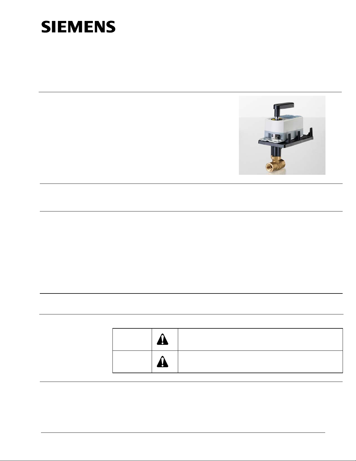
599 Series
2-Way Ball Valves
Description
The 599 Series Two-way Ball Valves are coupled with OpenAir™ actuators to provide
equal percentage flow control. The ball valves are 1/4-turn rotary control valves and are
available in 1/2-inch to 2-inch line sizes.
Technical Instructions
Document No. 155-703P25
VF 599-9
October 1, 2010
Features
Application
• 200 psi close-off with ANSI Class IV leakage for all line sizes and actuators.
• Available with chrome-plated brass ball and brass stem or
stainless steel ball and stem.
• Blow-out proof stem withstands high pressure.
• Universal mounting plate.
• Actuator and plate can be rotated (90 degree increments).
• Standoffs provide a thermal barrier between the actuator and the mounting plate.
• Operating handle for manual operation.
Ball valves can control hot or chilled water and up to 50% water-glycol solution in
convectors, fan coil units, unit conditioners, radiators, and reheat coils.
WARNING:
CAUTION:
Personal injury/loss of life may occur if you do not perform a
procedure as specified.
Equipment damage may occur if you do not perform a
procedure as specified.
Product Numbers
See Tables 2 through Table 7.
Siemens Industry, Inc.
Technical Instructions 599 Series 2-Way Ball Valves
Document Number 155-703P25
October 1, 2010
Specifications
Pressure rating 600 WOG
Media temperature 35°F to 250°F (2°C to 121°C)
Controlled medium Water, glycol solutions to 50%
Body
Brass: ASTM B283, C37700
Ball Chrome-plated brass or
Stainless steel
Ball seals Glass filled PTFE with EPDM O-rings
Flow characterizer Glass filled PTFE
End connections Female NPT
Stem Brass or stainless steel
Stem seals EPDM O-rings
Angle of rotation 0 to 90°
Close-off rating 200 psi (ANSI Class IV)
Dimensions and service envelope See
Figure 5
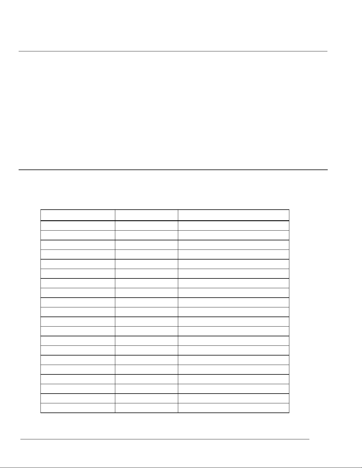
Ordering a Valve
Plus Actuator
Assembly
Actuator Prefix Code OpenAir Actuator * Control
171A GDE131.1P Floating, fail-in-place
171B GLB131.1P Floating, fail-in-place
171C GDE161.1P 0 to 10 Vdc, fail-in-place
171D GLB161.1P 0 to 10 Vdc, fail-in-place
171E GMA121.1P 2-position, fail-safe, normally open
171F GMA131.1P Floating, fail-safe, normally open
171G GMA161.1P 0 to 10 Vdc, fail-safe, normally open
171H GQD121.1P 2-position, fail-safe, normally open
171J GQD131.1P Floating, fail-safe, normally open
171K GQD151.1P 2 to 10 Vdc fail-safe, normally open
172E GMA121.1P 2-position, fail-safe, normally closed
172F GMA131.1P Floating, fail-safe, normally closed
172G GMA161.1P 0 to 10 Vdc, fail-safe, normally closed
172H GQD121.1P 2-position, fail-safe, normally closed
172J GQD131.1P Floating, fail-safe, normally closed
172K GQD151.1P 2 to 10 Vdc fail-safe, normally closed
173A GDE131.1Q** Floating, fail-in-place
173B GLB131.1Q** Floating, fail-in-place
173C GDE161.1Q** 0 to 10 Vdc, fail-in-place
173D GLB161.1Q** 0 to 10 Vdc, fail-in-place
*When ordered as an assembly, the actuator is provided with 3-foot (.9m) wires.
**When ordered as an assembly, the actuator is provided with conduit adapter and 6-foot (1.8m)
wires.
To order a complete valve plus actuator assembly from the factory, combine an
actuator prefix code (Table 1) with the suffix of the valve assembly product number.
Table 1. Actuator Prefix Codes.
Siemens Industry, Inc. Page 2
599 Series 2-Way Ball Valves Technical Instructions
3
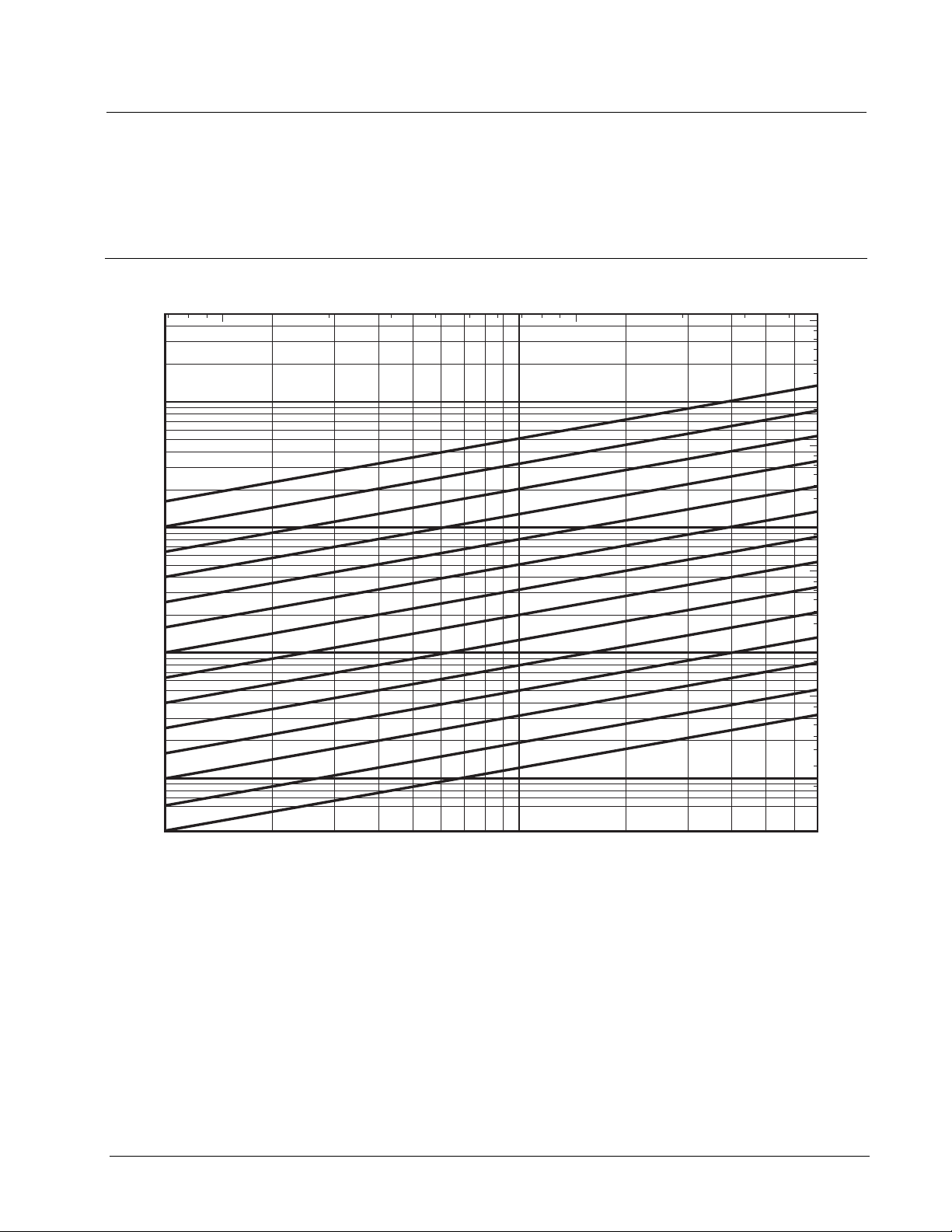
3/4”, 1“, 1-1/4", 1-1/2” Cv = 25
3/4”, 1“,1-1/4" Cv = 16
1/2”, 3/4”, 1" Cv = 10
1“, 1-1/4", 1-1/2”, 2" Cv = 40
1/2”, 3/4" Cv = 6.3
1/2" Cv = 4.0
1-1/2”, 2" Cv = 160
1-1/4", 1-1/2”, 2" Cv = 100
1“, 1-1/4", 1-1/2”, 2" Cv = 63
1/2" Cv = 2.5
1/2" Cv = 1.6
1/2" Cv = 1.0
1/2" Cv = 0.63
1/2" Cv = 0.40
Document Number 155-703P25
October 1, 2010
8 9 10
4000
3000
2000
1000
900
800
700
600
500
400
300
200
100
80
60
50
40
30
20
Flow Rate (GPM)
10
10
8
6
5
4
3
2
1 1
1
0.8
0.6
0.5
0.4
1
VF0335R2
See TB253 599 Series Ball Valve and Actuator Assemblies Selection Technical
Bulletin (155-704P25) for complete selection procedures and ordering numbers
for both two-way and three-way ball valve assemblies.
Individual two-way ball valves can be ordered using the product numbers in
Table 2 for valves with a chrome-plated ball and brass stem or Table 5 for
valves with stainless steel ball and stem.
Differential Pressure
20
2
3
30
40
50
1-1/4", 1-1/2”, 2" Cv = 100
1-1/4", 1-1/2”, 2" Cv = 100
1“, 1-1/4", 1-1/2”, 2" Cv = 63
1“, 1-1/4", 1-1/2”, 2" Cv = 63
1“, 1-1/4", 1-1/2”, 2" Cv = 40
1“, 1-1/4", 1-1/2”, 2" Cv = 40
3/4”, 1“, 1-1/4", 1-1/2” Cv = 25
3/4”, 1“, 1-1/4", 1-1/2” Cv = 25
4
5
6
7
Differential Pressure
8
Figure 1.
Δ
p (kPa)
60
70
1-1/2”, 2" Cv = 160
1-1/2”, 2" Cv = 160
3/4”, 1“,1-1/4" Cv = 16
3/4”, 1“,1-1/4" Cv = 16
1/2”, 3/4”, 1" Cv = 10
1/2”, 3/4”, 1" Cv = 10
9
10
100
80
90
100
1/2”, 3/4" Cv = 6.3
1/2”, 3/4" Cv = 6.3
1/2" Cv = 4.0
1/2" Cv = 4.0
1/2" Cv = 2.5
1/2" Cv = 2.5
1/2" Cv = 1.6
1/2" Cv = 1.6
1/2" Cv = 1.0
1/2" Cv = 1.0
1/2" Cv = 0.63
1/2" Cv = 0.63
1/2" Cv = 0.40
1/2" Cv = 0.40
Δ
p (psi)
200
20
30
300
40
50
400
1000
800
600
500
400
300
200
100
80
60
50
Flow Rate (m
40
30
20
10
8
6
/h)
5
4
3
2
1
0.8
0.6
0.5
0.4
0.3
0.2
60
70
Page 3 Siemens Industry, Inc.

Technical Instructions 599 Series 2-Way Ball Valves
Document Number 155-703P25
October 1, 2010
Table 2. Fail-In-Place Assemblies: Chrome-Plated Ball with Brass Stem.
Fail-in-Place
Valve
Body
Product
Cv
(Kvs)
Number *
599-10300 0.4 (0.34) 171A-10300 173A-10300 171C-10300 173C-10300
599-10301 0.63 (0.54) 171A-10301 173A-10301 171C-10301 173C-10301
599-10302 1.0 (0.9) 171A-10302 173A-10302 171C-10302 173C-10302
599-10303 1.6 (1.4) 171A-10303 173A-10303 171C-10303 173C-10303
599-10304 2.5 (2.2) 171A-10304 173A-10304 171C-10304 173C-10304
599-10305 4.0 (3.4) 171A-10305 173A-10305 171C-10305 173C-10305
599-10306 6.3 (5.4) 171A-10306 173A-10306 171C-10306 173C-10306
599-10307* 10 (8.6)
599-10308 6.3 (5.4) 171A-10308 173A-10308 171C-10308 173C-10308
599-10309 10 (8.6) 171A-10309 173A-10309 171C-10309 173C-10309
599-10310 16 (14) 171A-10310 173A-10310 171C-10310 173C-10310
599-10311* 25 (22)
599-10312 10 (9.0) 171A-10312 173A-10312 171C-10312 173C-10312
599-10313 16 (14) 171A-10313 173A-10313 171C-10313 173C-10313
599-10314 25 (22) 171A-10314 173A-10314 171C-10314 173C-10314
599-10315 40 (34) 171A-10315 173A-10315 171C-10315 173C-10315
599-10316* 63 (54)
599-10317 16 (14) 171A-10317 173A-10317 171C-10317 173C-10317
599-10318 25 (22) 171A-10318 173A-10318 171C-10318 173C-10318
599-10319 40 (34) 171A-10319 173A-10319 171C-10319 173C-10319
599-10320 63 (54) 171A-10320 173A-10320 171C-10320 173C-10320
599-10321* 100 (90)
599-10322 25 (22) 171B-10322 173B-10322 171D-10322 173D-10322
599-10323 40 (34) 171B-10323 173B-10323 171D-10323 173D-10323
599-10324* 63 (54) 171B-10324 173B-10324 171D-10324 173D-10324
599-10325 100 (90) 171B-10325 173B-10325 171D-10325 173D-10325
599-10326* 160 (140)
599-10327 40 (34) 171B-10327 173B-10327 171D-10327 173D-10327
599-10328 63 (54) 171B-10328 173B-10328 171D-10328 173D-10328
599-10329* 100 (90) 171B-10329* 173B-10329* 171D-10329* 173D-10329*
599-10330 160 (140)
Close-Off
∆P
PSI
200 PSI
Line
Size
Inches
(mm)
1/2
(15)
3/4
(20)
1 (25)
1 1/4
(30)
1 1/2
(40)
2 (50)
131.1P
*Denotes a full-port valve with no flow characterizer insert.
Floating
GDE
GLB
131.1P
3 foot (.9m)
Wires
171A 171B 173A 173B 171C 171D 173C 173D
171A-10307* 173A-10307* 171C-10307* 173C-10307*
171A-10311* 173A-10311* 171C-10311* 173C-10311*
171A-10316* 173A-10316* 171C-10316* 173C-10316*
171A-10321* 173A-10321* 171C-10321* 173C-10321*
171B-10326* 173B-10326* 171D-10326* 173D-10326*
171B-10330 173B-10330 171D-10330 173D-10330
GDE
131.1Q
Conduit Adapter
GLB
131.1Q
&
6-foot (1.8m)
Wires
Actuator Prefix Code
GDE
161.1P
3 foot (.9m)
Wires
0 to 10 Vdc
GLB
161.1P
GDE
161.1Q
Conduit Adapter
GLB
161.1Q
&
6-foot (1.8m)
Wires
Siemens Industry, Inc. Page 4
 Loading...