

Siemens 599-10304, 599-10300, 599-10303, 599-10305, 599-10306 Technical Instructions
...
599 Series
Technical Instructions
2- Way Ball Valves
Document No. 155-703P25
VF 599-9
February 4, 2016
Description
Features
Application
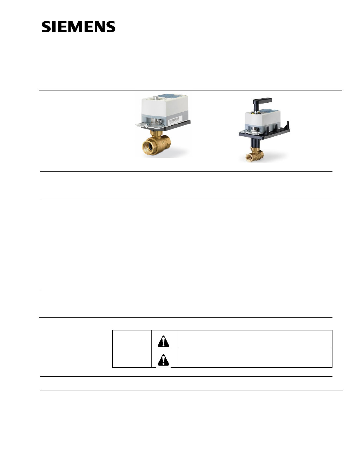
The 599 Series 2-way Ball Valves are coupled with OpenAir™ actuat ors to provide
equal percentage flow control. The ball valves are 1/4-turn rotary control valves and
are available in 1/2-inch to 2-inch line sizes.
· ANSI 250 valve body rating.
· 200 psi close-off with ANSI Cl ass IV leakage for all line sizes and actuators.
· Available with chrome-pl ated brass ball and brass stem or
stainless steel ball and stem.
· Blow-out proof stem withstands high pressure.
· Universal mounting plate.
· Actuator and plate can be rotated (90 degree increments).
· Standoffs provide a thermal barrier between the act uator and the m ounting
plate.
· Operating handle for manual operation.
Ball valves can control hot or chilled water and up t o 50% water-glycol solution i n
air handling units, convectors, fan coil units, unit conditioners, radiators, and reheat
coils.
WARNING:
Personal injury or loss of life may occur if you do not
perform a procedure as specified.
Product Numbers
Accessories/Kits
CAUTION:
See Error! Reference source not found. through Table 12.
599-10078 Ball Valve Bracket Kit
(includes bracket, mounting screws, shaft and handle)
599-10080 Ball Valve Weather Shield
(provides NEMA 3R protection)
Equipment dam age may occur if you do not perform a
procedure as specified.

Technical Instructions 599 Series 2-Way Ball Valves
Docume nt Numbe r 155-703P25
February 4, 20 16
Specifications
Material
Body Brass: ASTM B283, C37700
Ball Chrome-plated brass or stainl ess steel
Ball seals Glass filled PTFE with EPDM O-rings
Flow characterizer Glass filled PTFE
End connections Female NPT
St em Brass or stainl ess steel
Stem seals EPDM O-rings
Operating
Valve body rati ng ANSI 250/600 WOG
Media temperature 35°F to 250°F (2°C to 121°C)
Controlled medium Water, water-glycol solutions to 50%
Angle of rotation 0° to 90°
Close-off rati ng 200 psi (ANSI Class IV)
Miscellaneous
Canadian Registrat ion Number OC8213.5ADD4
Mounting location NEMA 1 (interior only)
Dimensions, service envelope, weight See Figure 6 and Table 14.
Ordering a
Valve/Actuator
To order a com plete valve plus actuator assembl y from the factory, combine an
actuator prefix code (see Table 1) with the suffix of the valve assembly product number.
Assembly
Table 1. Actuator Prefix Codes.
Actuator Prefix Code OpenAir Actuator * Control
171A GDE131.1P Floating, fail-in-place
171B GLB131.1P Floating, fail-in-place
171C GDE161.1P 0 to 10 Vdc, fail-in-place
171D GLB161.1P 0 to 10 Vdc, fail-in-place
171E GMA121.1P 2-position, fail-safe, normally open
171F GMA131.1P Floating, fail-safe, normally open
171G GMA161.1P 0 to 10 Vdc, fail-safe, normally open
171H GQD121.1P 2-position, fail-safe, normally open
171J GQD131.1P Floati ng, fail-safe, normally open
171K GQD151.1P 2 to 10 Vdc fail-safe, normally open
171L GQD221.1U 120V, 2-position, fail-safe, normally open
171M GMA221.1U 120V, 2-position, fail-safe, normally open
171N GQD126.1P 2-position, fail-safe, normally open, dual auxiliary switches
171P GMA126.1P 2-position, fail-safe, normally open, dual auxiliary switches
172E GMA121.1P 2-position, fail-safe, normally closed
172F GMA131.1P Floating, fail-safe, normally closed
172G GMA161.1P 0 to 10 Vdc, fail-safe, normally closed
172H GQD121.1P 2-position, fail-safe, normally closed
172J GQD131.1P Floati ng, fail-safe, normally closed
172K GQD151.1P 2 to 10 Vdc fail-safe, normally closed
172L GQD221.1U 120V, 2-position, fail-safe, normally closed
172M GMA221.1U 120V, 2-position, fail-safe, normally closed
172N GQD126.1P 2-position, fail-safe, normally closed, dual auxiliary switches
NEMA 3R (with weathershield)
Page 2 Siemens Industry, Inc.
599 Series 2-Way Ball Valves Technical Instructions
Actuator Prefix Code OpenAir Actuator * Control
172P GMA126.1P 2-position, fail-safe, normally closed, dual auxiliary switches
173A GDE131.1Q** Floating, fail-in-place
173B GLB131.1Q** Floating, fail-in-place
173C GDE161.1Q** 0 to 10 Vdc, fail-in-place
173D GLB161.1Q** 0 to 10 Vdc, fail-in-place
*When ordered as an assembly, the actuator is provided with 3-foot (.9 m) wires.
**When ordered as an assembly, the actuator is provided with conduit adapter and 6-foot (1.8 m) wires.
Docume nt Numbe r 155-703P25
February 4, 20 16
See TB253 599 Ser ies Ball Valve and Actuator Assemblies Selection Technical
Bulletin (155-704P25) for complete selection procedures and ordering numbers
for both two-way and three-way ball valve assemblies.
Individual two-way ball valves can be ordered using the product numbers i n
through Table 6 for valves with a chrome-plated ball and brass stem or Error!
Not a valid result for table. through Table 11 for valves with stainless steel ball
and stem.
Figure 1.
Page 3 Siemens Industry, Inc.

Technical Instructions 599 Series 2-Way Ball Valves
Conduit Adapter
Conduit Adapter
Docume nt Numbe r 155-703P25
February 4, 20 16
Table 2 . Fail-In Place Assemblies: Chrome-Plated Ball with Brass Stem (1/2-Inch and 3/4-Inch).
Fail-in-Place
Valve
Body
Product
Num ber *
599-10300
599-10301 0.63 (0.54) 171A-10301 173A-10301 171C-10301 173C-10301
599-10302 1.0 (0.9) 171A-10302 173A-10302 171C- 1030 2 173C-1030 2
599-10303 1.6 (1.4) 171A-10303 173A-10303 171C-10303 173C-10303
599-10304 2.5 (2.2) 171A-10304 173A-10304 171C-10304 173C-10304
599-10305 4.0 (3.4) 171A-10305 173A-10305 171C-10305 173C-10305
599-10306 6.3 (5.4) 171A-10306 173A-10306 171C-10306 173C-10306
599-10307* 10 (8.6) 171A-10307* 173A-10307* 171C-10307* 173C-10307*
599-10308
599-10309 10 (8.6) 171A-10309 173A-10309 171C-10309 173C-10309
599-10310 16 (14) 171A-10310 173A-10310 171C-10310 173C-10310
599-10311* 25 (22) 171A-10311* 173A-10311* 171C-10311* 173C-10311*
Valve
Size
Inches
(mm)
1/2
(15)
3/4
(20)
Flow Rate
Cv
(Kvs)
3 foot (.9m)
Close-Off ∆P in psi (kPa)
0.4 (0.34)
6.3 (5.4) 171A-10308 173A-10308 171C-10308 173C-10308
171A-10300 173A-10300 171C-10300 173C-10300
200 (1379)
Floating 0 to 10 Vdc
GDE
131.1P
Wires
171A 173A 171C 173C
*Denotes a full-port valve without flow characterizers insert.
Table 3. Fail-In-Place Assemblies: Chrome-Plated Ball with Brass Stem (1-Inch to 2-Inch)
GDE
131.1Q
Conduit Adapter
&
6-foot (1.8m)
Wires
Actuator Prefix Code
Fail-in-Place
GDE
161.1P
3 foot (.9m)
Wires
GDE
161.1Q
Conduit Adapter
&
6-foot (1.8m)
Wires
Valve
Body
Product
Num ber *
599-10312
599-10313 16 (14) 171A-10313 173A-10313 171C-10313 173C-10313
599-10314 25 (22) 171A-10314 173A-10314 171C-10314 173C-10314
599-10315 40 (34) 171A-10315 173A-10315 171C-10315 173C-10315
599-10316* 63 (54) 171A-10316* 173A-10316* 171C-10316* 173C-10316*
599-10317
599-10318 25 (22) 171A-10318 173A-10318 171C-10318 173C-10318
599-10319 40 (34) 171A-10319 173A-10319 171C-10319 173C-10319
599-10320 63 (54) 171A-10320 173A-10320 171C-10320 173C-10320
599-10321* 100 (90) 171A-10321* 173A-10321* 171C-10321* 173C-10321*
599-10322
599-10323 40 (34) 171B-10323 173B-10323 171D-10323 173D-10323
599-10324* 63 (54) 171B-10324* 173B-10324* 171D-10324* 173D-10324*
599-10325 100 (90) 171B-10325 173B-10325 171D-10325 173D-10325
599-10326* 160 (140) 171B-10326* 173B-10326* 171D-10326* 173D-10326*
599-10327
599-10328 63 (54) 171B-10328 173B-10328 171D-10328 173D-10328
599-10329* 100 (90) 171B-10329* 173B-10329* 171D-10329* 173D-10329*
599-10330* 160 (140) 171B-10330* 173B-10330* 171D-10330* 173D-10330*
Valve
Size
Inches
(mm)
1 (25)
1 1/4
(32)
1 1/2
(40)
2 (50)
Flow Rate
Cv
(Kvs)
GDE
131.1P
3 foot (.9m)
Close-Off ∆P in psi (kPa)
171A 171B 173A 173B 171C 171D 173C 173D
10 (9.0)
16 (14) 171A-10317 173A-10317 171C-10317 173C-10317
25 (22) 171B-10322 173B-10322 171D-10322 173D-10322
40 (34) 171B-10327 173B-10327 171D-10327 173D-10327
171A-10312 173A-10312 171C-10312 173C-10312
200 (1379)
Floating 0 to 10 Vdc
GLB
131.1P
Wires
GDE
131.1Q
&
6-foot (1.8m)
Wires
GLB
131.1Q
Actuator Prefix Code
GDE
161.1P
3 foot (.9m)
Wires
GLB
161.1P
GDE
161.1Q
&
6-foot (1.8m)
Wires
GLB
161.1Q
*Denotes a full-port valve without flow characterizers insert.
Page 4 Siemens Industry, Inc.
 Loading...