

Page 1

Siemens Industry, Inc.
Flowrite™ 599 Series
Technical Instructions
Document Number 155-758
June 14, 2019
High Pressure Close-Off 2-Way
Valves, 2-1/2 to 6-Inch, Flanged Iron
Body, ANSI Classes 125 & 250
Description
The Flowrite 599 Series High Pressure Close-off, two-way flanged valve bodies, are
designed to work with either pneumatic or electronic actuators with 3/4-inch (20 mm) or
1-1/2-inch (40 mm) stroke. They are available in both ANSI Class 125 and 250 for
normally open or normally closed action.
Features
• Valve flange face-to-face dimensions meet ISA 75.03 standards.
• Universal bonnet for direct-coupled actuators
• Equal percentage flow characteristic
• Stainless steel trim
• ANSI Leakage Class IV
• EPDM O-ring packing
Application
These Flowrite valves are recommended for chilled or hot water; or 50% water-glycol
solutions.
• ANSI 125 and ANSI 250 cast iron body rating.
• Maximum recommended differential pressure for modulating service; 50 psi (345 kPa).
Product Numbers
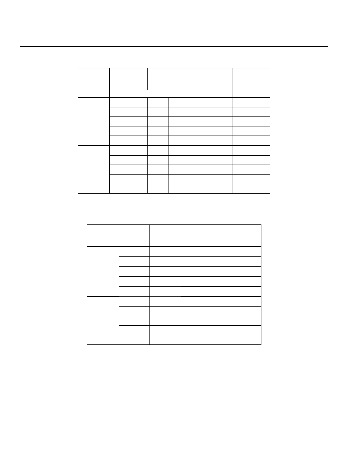
See Tables 1 and 2.
Ordering a Valve
Plus Actuator
Assembly
To order a complete valve plus actuator assembly from the factory, combine the actuator
prefix code with the suffix of the valve assembly product number. Valves can be ordered
using the numbers in Tables 1 and 2.
Page 2
Technical Instructions Flowrite™ 599 Series High Pressure Close-Off Two-Way Valves 2-1/2 to 6-inch
Document Number 155-758 Flanged Iron Body, ANSI Classes 125 and 250
June 14, 2019
Page 2 Siemens Industry, Inc.
Table 1. Product Numbers for ANSI 125 Valves.
Action
Flow Rate
Valve
Line Size
Stroke
Valve Part
Number
Cv
(Kvs)
Inch
(mm)
Inch
(mm)
Normally
Open
63
(54)
2-1/2
(65)
3/4
(20)
599-06610
100
(85)
3
(80)
3/4
(20)
599-06611
160
(137)
4
(100)
1-1/2
(40)
599-06612
250
(214)
5
(125)
1-1/2
(40)
599-06613
400
(340)
6
(150)
1-1/2
(40)
599-06614
Normally
Closed
63
(54)
2-1/2
(65)
3/4
(20)
599-06615
100
(85)
3
(80)
3/4
(20)
599-06616
160
(137)
4
(100)
1-1/2
(40)
599-06617
250
(214)
5
(125)
1-1/2
(40)
599-06618
400
(340)
6
(150)
1-1/2
(40)
599-06619
Table 2. Product Numbers for ANSI 250 Valves.
Action
Flow Rate
Valve
Line Size
Stroke
Valve Part
Number
Cv (Kvs)
Inch (mm)
Inch
(mm)
Normally
Open
63 (54)
2-1/2 (65)
3/4
(20)
599-06620
100 (85)
3 (80)
3/4
(20)
599-06621
160 (137)
4 (100)
1-1/2
(40)
599-06622
250 (214)
5 (125)
1-1/2
(40)
599-06623
400 (340)
6 (150)
1-1/2
(40)
599-06624
Normally
Closed
63 (54)
2-1/2 (65)
3/4
(20)
599-06625
100 (85)
3 (80)
3/4
(20)
599-06626
160 (137)
4 (100)
1-1/2
(40)
599-06627
250 (214)
5 (125)
1-1/2
(40)
599-06628
400 (340)
6 (150)
1-1/2
(40)
599-06629
Page 3
Flowrite™ 599 Series High Pressure Close-Off Two-Way Valves 2-1/2 to 6-inch Technical Instructions
Flanged Iron Bodies ANSI Classes 125 and 250 Document Number 155-758
June 14, 2019
Siemens Industry, Inc. Page 3
Specifications
Valve size 2-1/2 to 6-inch (65 to 150 mm)
Capacity See Tables 5 and 6, and Figure 2
Body style Flanged
Seat style Single seat, metal-to-metal
Action Normally Open (NO)
Normally Closed (NC)
Stem travel (stroke)
2-1/2 and 3-inch 3/4-inch (20 mm)
4, 5, and 6-inch 1-1/2-inch (40 mm)
Valve body rating ANSI Class 125 and 250; see Table 4
Material
Body Cast iron ASTM A126 Class B
Body trim Stainless steel
Stem Stainless steel ASTM A582 Type 303
Packing EPDM O-ring
Controlled medium Water, 50% water-glycol solutions
Medium temperature range 20°F to 250°F (-7°C to 120°C)
Operating
Maximum recommended differential
pressure for modulating service 50 psi (345 kPa)
Rangeability >100:1
Close-off pressures See Tables 7 and 8
Close-off ratings According to ANSI/FCI 70-2
Leakage rate Class IV (0.01% of Cv)
Flow characteristic Equal Percentage
Miscellaneous
Canadian Registration Numbers 0H7645.5
0C0838.9
Mounting location NEMA 1 (interior only)
Flange mounting according to ANSI B16.1 See 155-303P25 (TB 248)
Dimensions See Tables 14, and Figure 7
Face-to-face dimensions ANSI/ISA S75.03
Valve weight See Table 14
Accessories
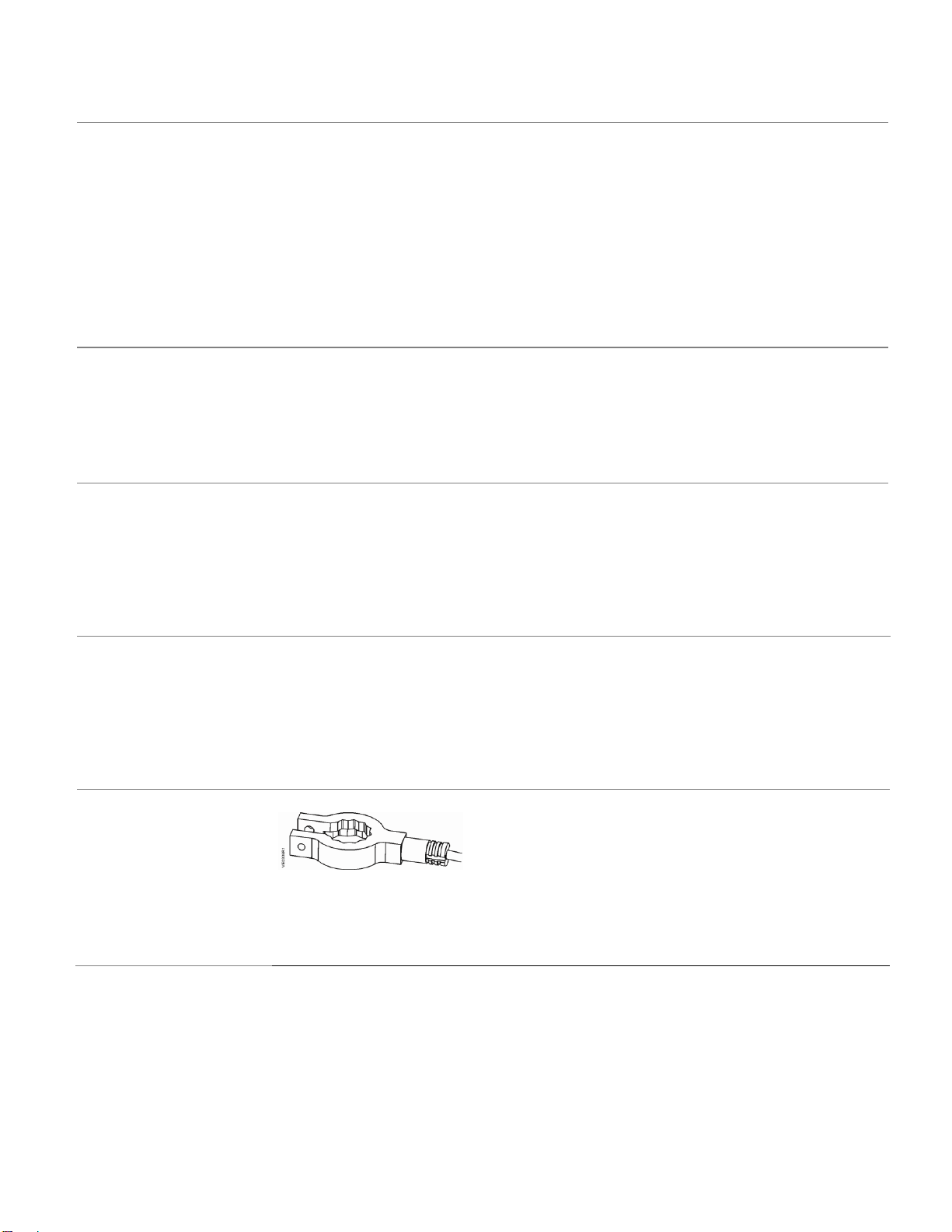
Figure 1. Stem Heating Element.
ASZ6.6 The stem heating element
prevents the formation of ice on the stem
when the medium temperature drops
below 32°F (0°C). It is suited for universal
use with valves having a stem or spindle
diameter of 10 or 14 mm.
Operating Voltage 24 Vac/dc ± 20%
Power consumption ≤ 40 VA/30W
St
Page 4
Technical Instructions Flowrite™ 599 Series High Pressure Close-Off Two-Way Valves 2-1/2 to 6-inch
Document Number 155-758 Flanged Iron Body, ANSI Classes 125 and 250
June 14, 2019
Page 4 Siemens Industry, Inc.
Warning/Caution Notations
WARNING:
Personal injury or loss of life may occur if you do not perform
a procedure as specified.
CAUTION:
Equipment damage may occur if you do not perform a
procedure as specified.
Service Kits
Packing kit 599-08020
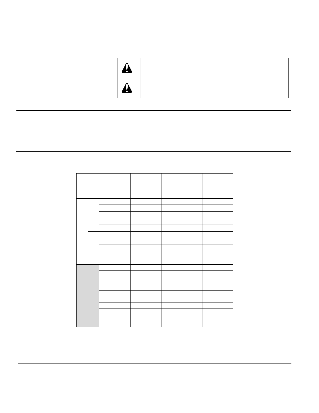
Rebuild/repack kits See Table 3
Stem retainer kit:
2-1/2-inch and 3-inch valves 599-10048
4-inch, 5-inch, and 6-inch valves 599-10049
Table 3. Rebuild/Repack Service Kits.
ANSI
Action
Valve
Body
Valve
Size
Inch (mm)
Cv
Stroke
Kit No.
ANSI 125
Normally
Open
599-06610
2-1/2 (65)
63
3/4 (20)
599-09250
599-06611
3 (80)
100
3/4 (20)
599-09251
599-06612
4 (100)
160
1-1/2 (40)
599-09252
599-06613
5 (125)
250
1-1/2 (40)
599-09253
599-06614
6 (150)
400
1-1/2 (40)
599-09254
Normally
Closed
599-06615
2-1/2 (65)
63
3/4 (20)
599-09255
599-06616
3 (80)
100
3/4 (20)
599-09256
599-06617
4 (100)
160
1-1/2 (40)
599-09257
599-06618
5 (125)
250
1-1/2 (40)
599-09258
599-06619
6 (150)
400
1-1/2 (40)
599-09259
ANSI 250
Normally
Open
599-06620
2-1/2 (65)
63
3/4 (20)
599-09250
599-06621
3 (80)
100
3/4 (20)
599-09251
599-06622
4 (100)
160
1-1/2 (40)
599-09252
599-06623
5 (125)
250
1-1/2 (40)
599-09253
599-06624
6 (150)
400
1-1/2 (40)
599-09254
Normally
Closed
599-06625
2-1/2 (65)
63
3/4 (20)
599-09255
599-06626
3 (80)
100
3/4 (20)
599-09256
599-06627
4 (100)
160
1-1/2 (40)
599-09257
599-06628
5 (125)
250
1-1/2 (40)
599-09258
599-06629
6 (150)
400
1-1/2 (40)
599-09259
Page 5
Flowrite™ 599 Series High Pressure Close-Off Two-Way Valves 2-1/2 to 6-inch Technical Instructions
Flanged Iron Bodies ANSI Classes 125 and 250 Document Number 155-758
June 14, 2019
Siemens Industry, Inc. Page 5
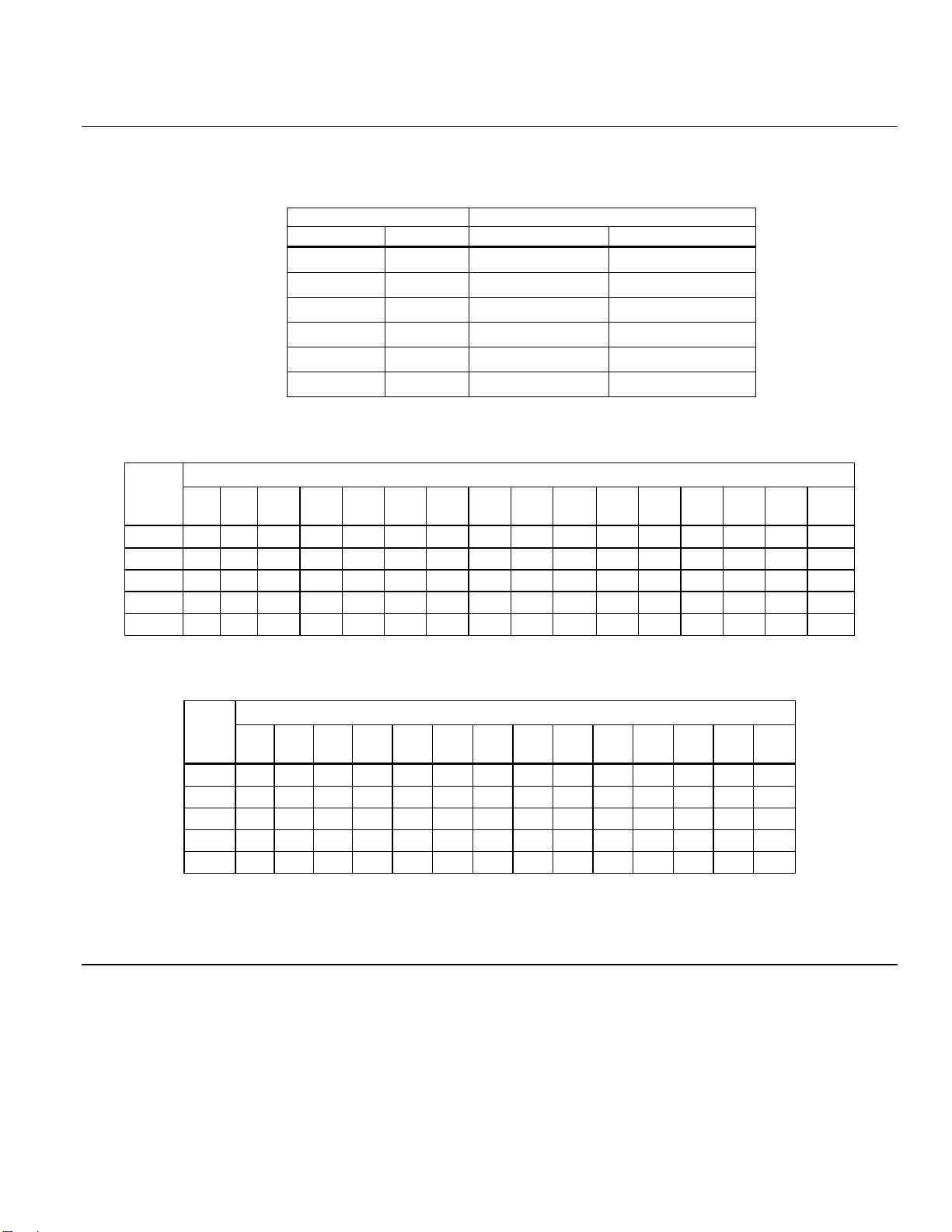
Table 4. Cast Iron Valve Body Ratings.
Temperature
Pressure psig (kPa)
°F
°C
ANSI Class 125
ANSI Class 250
–20 to 150
–30 to 66
200 (1387)
500 (3447)
200
93
190 (1310)
460 (3171)
250
121
175 (1206)
415 (2861)
300
149
165 (117)
375 (2585)
400
204
140 (965)
290 (1999)
450
232
125 (861)
250 (1723)
Table 5. Maximum Water Capacity - U.S. Gallons per Minute.
Valve
Size
Inches
Pressure Differential - psi
Cv\1 2 3 4 5 6 8 10
15
20
25
30
40
50
60
75
2-1/2
63
89
109
126
141
154
178
199
244
282
315
345
398
445
488
546
3
100
141
173
200
224
245
283
316
387
447
500
548
632
707
775
866
4
160
226
277
320
358
392
453
506
620
716
800
876
1012
1131
1239
1386
5
250
354
433
500
559
612
707
791
968
1118
1250
1369
1581
1768
1936
2165
6
400
566
693
800
894
980
1131
1265
1549
1789
2000
2191
2530
2828
3098
3464
Table 6. Maximum Water Capacity - Cubic Meters per Hour (m3/hr).
Valve
Size
mm
Pressure Differential - kPa
1
10
20
30
40
50
60
80
Kvs/
100
150
200
300
400
500
65
5.4
17.1
24
30
34
38
42
48
54
66
76
94
108
121
80
8.5
27
38
47
54
60
66
76
85
104
120
147
170
190
100
14
43
61
75
87
97
106
123
137
168
194
237
274
306
125
21
68
96
117
135
151
166
191
214
262
303
371
428
479
150
34
108
153
187
216
242
265
306
342
419
484
592
684
765
Page 6
Technical Instructions Flowrite™ 599 Series High Pressure Close-Off Two-Way Valves 2-1/2 to 6-inch
Document Number 155-758 Flanged Iron Body, ANSI Classes 125 and 250
June 14, 2019
Page 6 Siemens Industry, Inc.
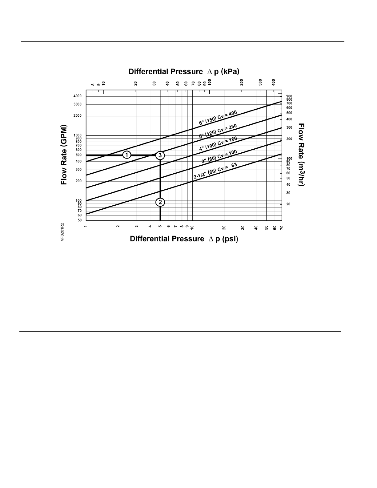
Figure 2. Water Capacity Graph.
Selection Example
Select a valve given:
Required flow = 500 gpm
Desired pressure drop = 5 psi
Select a 5-inch (125 mm) valve, Cv 250.
Page 7
Flowrite™ 599 Series High Pressure Close-Off Two-Way Valves 2-1/2 to 6-inch Technical Instructions
Flanged Iron Bodies ANSI Classes 125 and 250 Document Number 155-758
June 14, 2019
Siemens Industry, Inc. Page 7
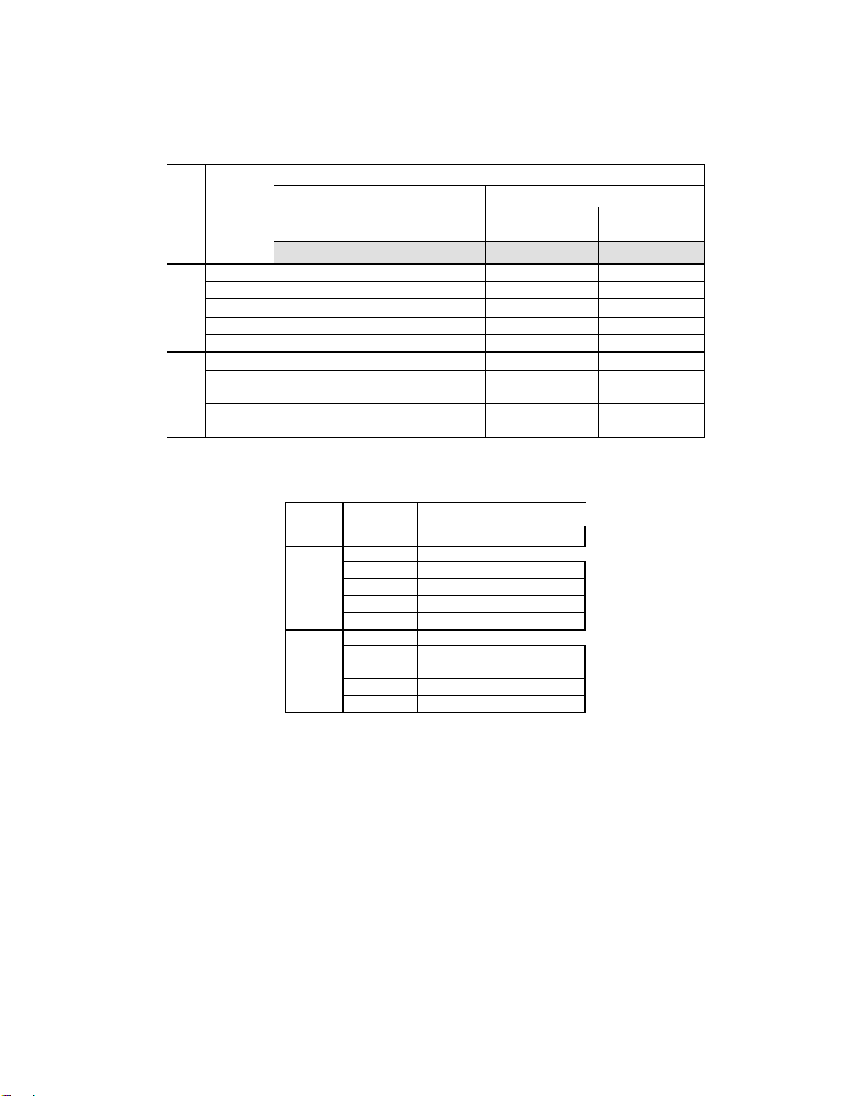
Table 7. Close-off Pressures for Pneumatic Actuators.
Table 8. Close-off Pressures for Electronic Actuators
Action
Valve Size
In (mm)
Electro-Hydraulic 24 Vac
SKD
SKC
Normally
Open
2-1/2 (65)
200 (1378)
—
3 (80)
200 (1378)
—
4 (100)
—
200 (1378)
5 (125)
—
200 (1378)
6 (150)
—
200 (1378)
Normally
Closed
2-1/2 (65)
200 (1378)
—
3 (80)
200 (1378)
—
4 (100)
—
200 (1378)
5 (125)
—
200 (1378)
6 (150)
—
200 (1378)
Action
Valve
Size,
Inch
(mm)
Spring Return
8- Inch
12-Inch
3 to 8 psi
(21 to 55 kPa)
10 to 15 psi
(69 to 103 kPa)
3 to 8 psi
(21 to 55 kPa)
10 to 15 psi
(69 to 103 kPa)
15 psi (103 kPa)
0 psi (0 kPa)
Normall
y
Open
2-1/2 (65)
200 (1378)
— — —
3 (80)
200 (1378)
— — —
4 (100)
—
—
200 (1378)
—
5 (125)
—
—
200 (1378)
—
6 (150)
—
—
200 (1378)
—
Normally
Closed
2-1/2 (65)
—
200 (1378)
—
—
3 (80)
—
200 (1378)
—
—
4 (100)
— — —
200 (1378)
5 (125)
— — —
200 (1378)
6 (150)
— — —
200 (1378)
Page 8

Technical Instructions Flowrite™ 599 Series High Pressure Close-Off Two-Way Valves 2-1/2 to 6-inch
Document Number 155-758 Flanged Iron Body, ANSI Classes 125 and 250
June 14, 2019
Page 8 Siemens Industry, Inc.
Operation
Figure 3 shows the normally open valve in the open or full flow position and the normally
closed valve in the closed, or zero flow position. The actuator spring provides the necessary
force to hold the stem in the raised or normal position.
In the event of power failure, a spring return actuator returns the valve to its normal
position.
Non-spring return actuators will hold the last commanded position. See the Technical
Instructions of the various actuators for additional information.
Normally Open Normally Closed
Figure 3. Operation.
Sizing
The sizing of a valve is important for correct system operation. An undersized valve will not
have sufficient capacity at maximum load. An oversized valve may initiate cycling, and the
seat and throttling plug may be damaged because of the restricted opening. Correct sizing
of the control valve for actual expected conditions is considered essential for good control.
Some variables which must be determined are:
• The water and 50% water-glycol solutions, are the controlled mediums.
• The pressure differential that will exist across the valve under maximum load
demand.
• The maximum capacity the valve must deliver.
• The maximum line pressure differential that the valve actuator must close against.
See Tables 5 through 6, and Figure 2 for valve capacities and sizing selection.
Page 9
Flowrite™ 599 Series High Pressure Close-Off Two-Way Valves 2-1/2 to 6-inch Technical Instructions
Flanged Iron Bodies ANSI Classes 125 and 250 Document Number 155-758
June 14, 2019
Siemens Industry, Inc. Page 9
Installation
Install the valve so that the flow follows the direction of the arrow indicated on the valve
body identification tag.
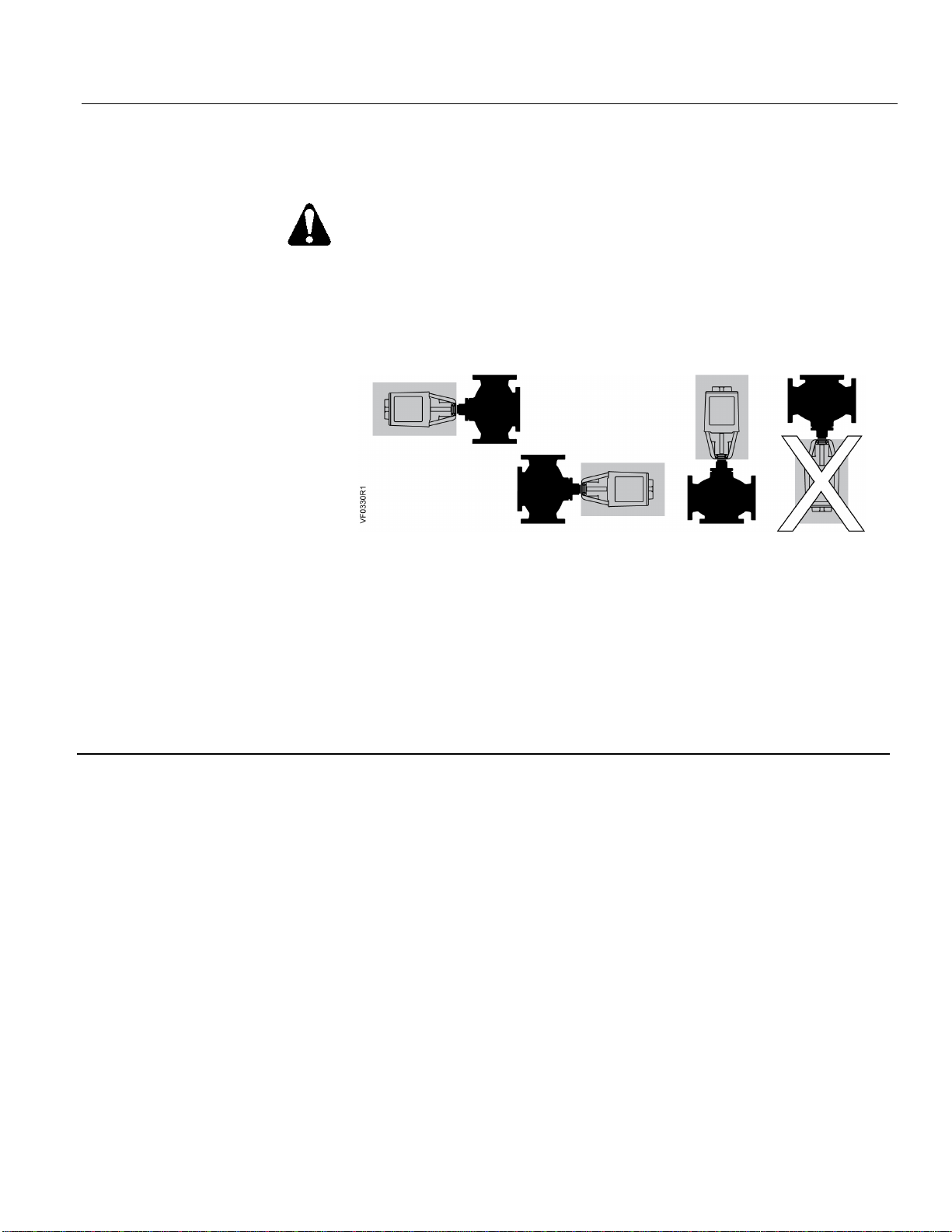
CAUTION:
Install the valve assembly with the actuator above the valve body. The
valve and actuator can be installed in any position between:
• Horizontal to the valve; and
• Vertical above the valve.
It is not recommended to install the valve assembly below horizontal or
upside down.
Figure 4. Recommended Installation Orientations.
• For flange dimensions and bolt hole information, see 155-303P25 (TB 248).
• Allow sufficient space for servicing the valve and actuator. See Table 11 for valve
body dimensions. See Figure 7 and Table 10 for dimensions of the service
envelope recommended around the actuator.
NOTE: Instructions for field mounting an actuator, spring adjustments, wiring diagrams,
and start-up are covered in the Technical Instructions and Installation Instructions
for each actuator.
Page 10
Technical Instructions Flowrite™ 599 Series High Pressure Close-Off Two-Way Valves 2-1/2 to 6-inch
Document Number 155-758 Flanged Iron Body, ANSI Classes 125 and 250
June 14, 2019
Page 10 Siemens Industry, Inc.
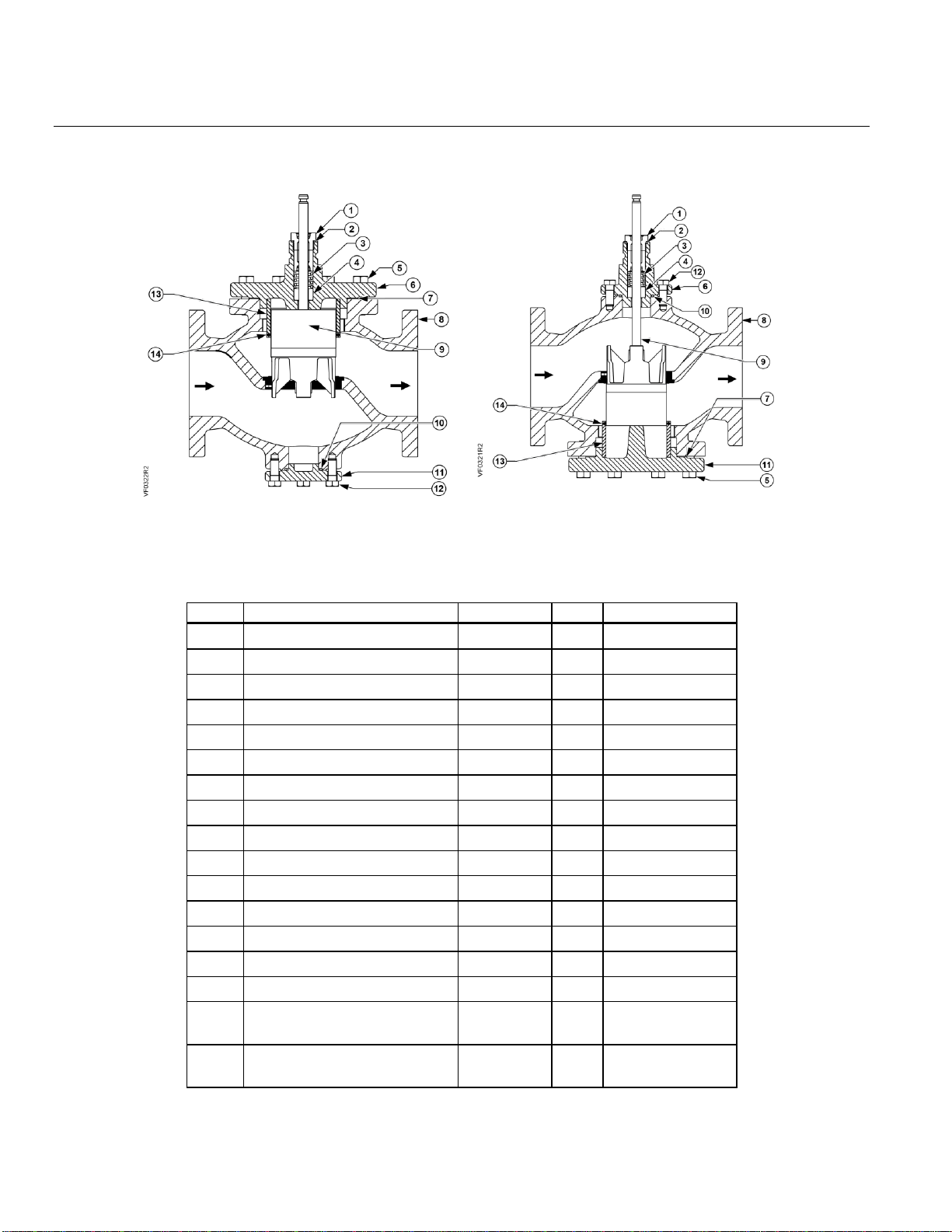
Construction of the Two-Way Valve
Figure 5. Two-Way Normally Open.
Figure 6. Two-Way Normally Closed.
Parts List
Table 9. Parts List for Two-Way Flanged Valves.
Item
Part Name
Part No.
Qty
Material
1
Packing Cartridge Assembly
— 1 —
2
Gasket
— 1 Copper
3
Packing Spring
—
1
Stainless Steel
4
Packing Bearing
— 1 Bronze
5
Cap Screw
—
4–8
Plated Steel
6
Bonnet
— 1 Cast Iron
7
Gasket
— 1 —
8
Valve Body
— 1 Cast Iron
9
Stem and Plug Assembly
—
1
Stainless Steel
10
O-ring
— 1 EPDM
11
Cap — 1
Cast Iron
12
Cap Screw
—
4
Plated Steel
—
Packing Kit
599-08020
—
Items 1, 2,3 & 4
13
Sleeve
— 1 Cast Iron
14
Sleeve Seal
— 1 —
—
Rebuild/Repack Kit
Normally Open
Table 3
—
Items 1, 2, 3, 4,
7, & 9
—
Rebuild/Repack Kit
Normally Closed
Table 3
—
Items 1, 2, 3, 4,
7, 9
______________________________________________________________________________________________
Page 11
Flowrite™ 599 Series High Pressure Close-Off Two-Way Valves 2-1/2 to 6-inch Technical Instructions
Flanged Iron Bodies ANSI Classes 125 and 250 Document Number 155-758
June 14, 2019
Siemens Industry, Inc. Page 11
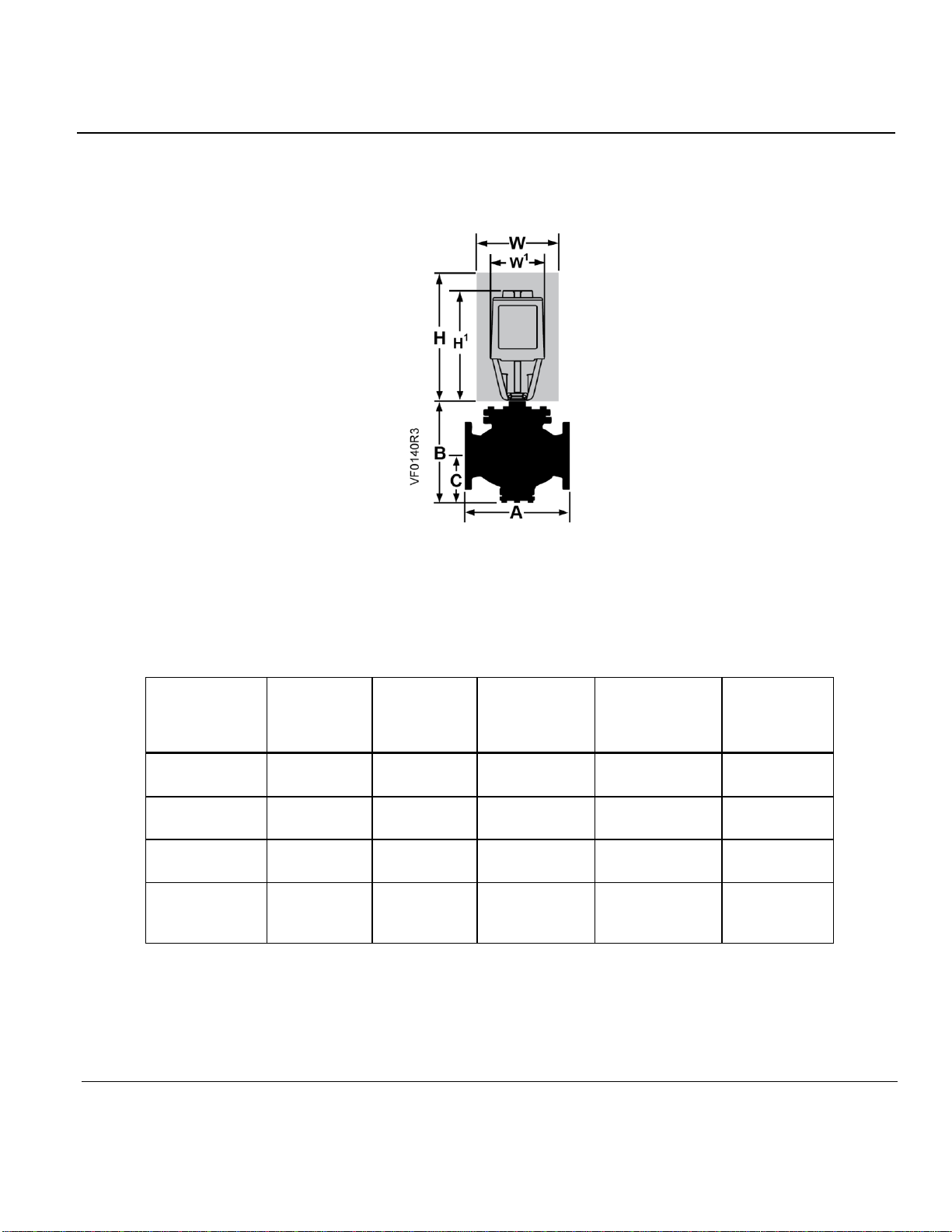
Dimensions
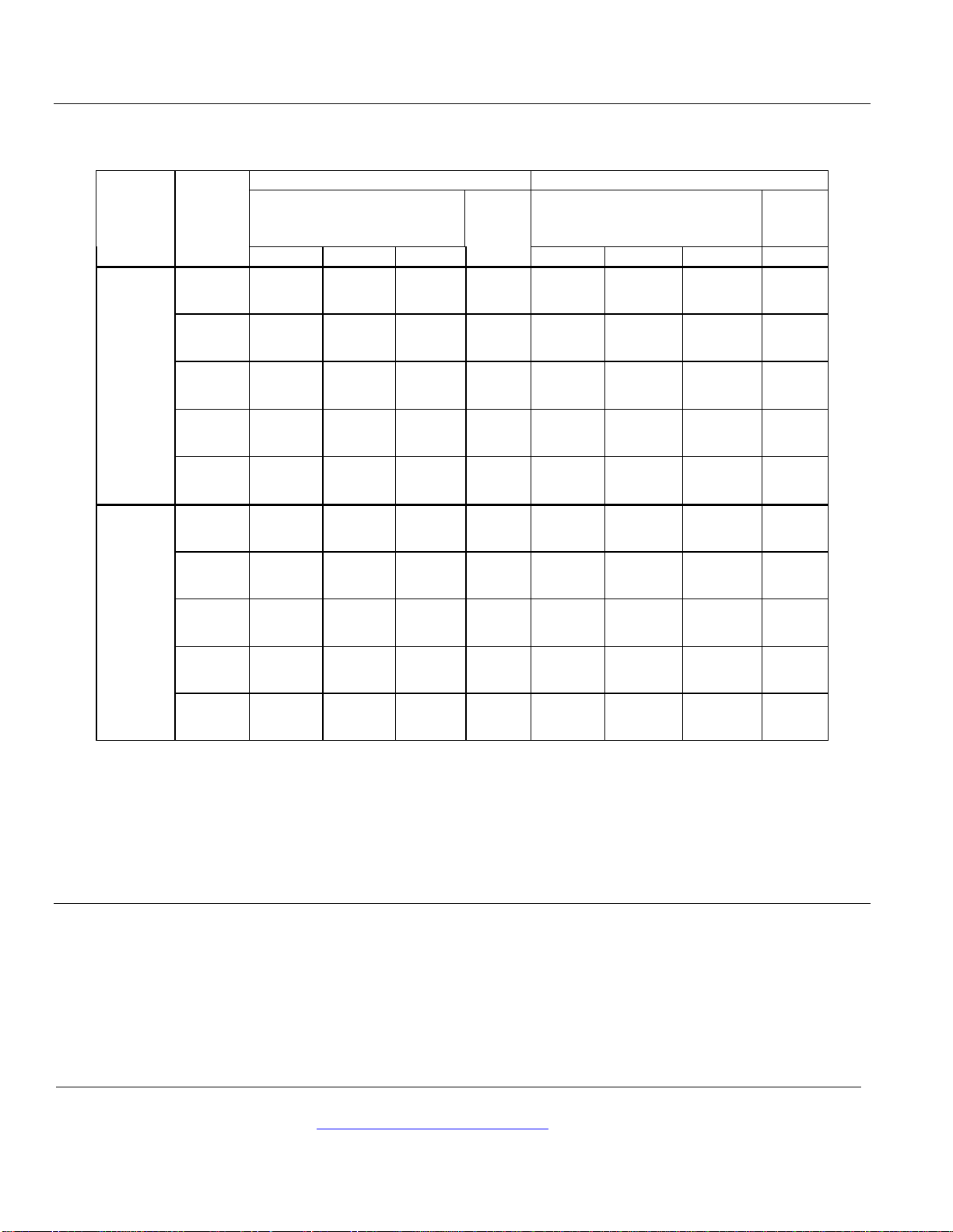
NOTE: See Table 10 for actuator and recommended service envelope dimensions and Table 11 for actual valve
dimensions.
Figure 7 Dimensions.
Table 10. Dimensions of the Actuator and Recommended Service Envelope.
Dimensions in Inches (Millimeters).
Actuator
Prefix
Code
Actual
Height of
Actuator
H1
Service Height
H
Actuator
Width or
Diameter of W1
Service
Width
W
8” Pneumatic
283
14-1/8
(359)
26 (660)
8-3/4 (222)
diameter
21 (450)
12" Pneumatic
287
17-7/8
(454)
30 (762)
15-1/8 (384)
diameter
27 (686)
SKD
274
11-13/16
(300)
19-3/4 (430)
6-5/8 (170) width
14-1/2 (360)
SKC with
handle closed
294
14-3/4
(375)
22-3/4 (578)
7 (178) Width ×
8-15/16 (226)
Depth
25 (635)
Page 12
Technical Instructions Flowrite™ 599 Series High Pressure Close-Off Two-Way Valves 2-1/2 to 6-inch
Document Number 155-758 Flanged Iron Body, ANSI Classes 125 and 250
June 14, 2019
Information in this publication is based on current specifications. The company reserves the right to make changes in specifications and models as
design improvements are introduced. Flowrite is a trademark of Siemens Industry, Inc. Product or company names mentioned herein may be the
trademarks of their respective owners. © 2019 Siemens Industry, Inc.
Siemens Industry, Inc.
Smart Infrastructure
1000 Deerfield Parkway
Buffalo Grove, IL 60089
+ 1 847-215-1000
Your feedback is important to us. If you have comments
about this document, please send them to
Document No. 155- 758
Printed in the USA
Page 12
Table 11. Valve Dimensions and Weight.
Action
Valve
Size
inch
(mm)
ANSI Class 125
ANSI Class 250
Dimensions
Inches (mm)
Weight
lbs.
(kg)
Dimensions
Inches (mm)
Weight
lbs.
(kg) A B C A B C
Normally
Open
2-1/2
(65)
11
(276)
11
(281)
4-7/8
(123)
62
(28)
11-1/2
(292)
11
(281)
5
(123)
78
(35)
3
(80)
11-3/4
(299)
12-1/4
(312)
5-5/16
(135)
79
(35)
12-1/2
(318)
12-1/4
(312)
5-5/16
(135)
102
(46)
4
(100)
14
(352)
13-9/16
(345)
6-5/16
(160)
129
(58)
14-1/2
(368)
13-5/8
(344.7)
6-5/16
(160)
165
(75)
5
(125)
15-3/4
(400)
15-3/16
(385)
7
(177)
162
(73)
16-5/8
(422)
15-3/16
(385)
7
(177)
215
(97)
6
(150)
17-3/4
(451)
16-3/4
(426)
8
(200)
222
(101)
18-5/8
(473)
16-3/4
(426)
8
(200)
312
(142)
Normally
Closed
2-1/2
(65)
11
(276)
10-5/8
(269)
5
(125)
60
(27)
11-1/2
(292)
11
(279)
5-3/8
(135)
76
(35)
3
(80)
11-3/4
(299)
12
(303)
5-5/8
(142)
78
(35)
12-1/2
(318)
12-7/16
(315)
6
(154)
101
(45)
4
(100)
14
(352)
14
(354)
6-5/8
(168)
128
(58)
14-1/2
(368)
14-3/8
(364)
7
(178)
164
(74)
5
(125)
15-3/4
(400)
15-1/4
(388)
7-1/2
(185)
160
(72)
16-5/8
(422)
15-3/4
(399)
7-3/4
(196)
214
(97)
6
(150)
17-3/4
(451)
17-1/16
(433)
8-3/16
(207)
219
(100)
18-5/8
(473)
17-1/2
(444)
8-5/8
(218)
309
(141)
 Loading...