

Siemens 599-03198, 599-03144, 599-03146, 599-03200, 599-03201 Technical Instructions
...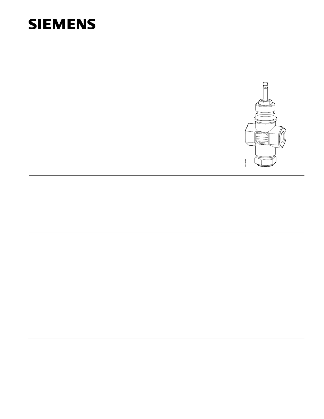
Flowrite™ 599 Seri es
Technical Instructions
Three-Way Valves
• Direct-coupled universal bonnet
1/2 to 2-inch Bronze Body
Document No. 155-185P25
VF 599-4
June 10, 2014
Description
Features
Application
Product Numbers
Ordering a Valve
Plus Actuator
Assembly
The Flowrite VF 599 Series ANSI Class 250 three-way valves are designed to work with
either a pneumatic or electronic actuator with a 3/4-inch (20 mm) stroke.
• ANSI Leakage Class IV (0.01% of Cv)
• Cartridge type packing
• Choice of brass or stainless steel trim
A typical application for the Flowrite three-way valve is the mixing of two different
temperatures of water supplies.
The valve can also be used for throttling or bypass coil control applications. A pump is
recommended on the coil circuit to improve the heat transfer characteristics of the coil
and for freeze protection.
See Table 1.
To order a complete valve plus actuator assembly from the factory, combine the
actuator prefix code with the suffix of the valve assembly product number. See Flowrite
Technical Bulletins 155-772 and 155-776 for complete selection procedure and ordering
codes.
Valve assemblies can be ordered using the valve part numbers in Table 1 and the
actuator prefix codes in Table 7.
Siemens Industry, Inc.

Technical Instructions Flowrite 599 Series Three-Way Valves
Controlled medium 50% water-glycol solutions
Canadian Registration Numbers 0H7645.5ADD2
Document Number 155-185P25
June 10, 2014
Specifications
Material
Operating
Line size 1/2 to 2 inches (15 to 50 mm)
Capacity See Table 2, Table 3 and Figure 3.
Body style Globe style
Seat style Metal-to-metal
Action Three-way mixing
Valve body rating ANSI Class 250. See Table 4.
Stem travel (Stroke) 3/4-inch (20 mm)
Body UNS CA 844 bronze
Body trim See Table 1.
Stem Stainless steel ASTM A582 Type 303
Packing EPDM O-rings
Medium temperature range 20°F to 250°F (-7°C to 120°C)
Maximum inlet pressure See Table 4.
Maximum recommended differential pressure for modulating service
Bronze trim 25 psi (173 kPa)
Stainless Steel trim 50 psi (345) kPa)
Rangeability > 100:1
Close-off pressures See Table 5, Table 6, and Figure 4.
Close-off ratings According to ANSI/FCI 70-2
Leakage rate Class IV (0.01% of Cv)
Flow characteristics Equal percentage for NC
Linear for NO
Mounting location NEMA 1 (interior only)
Miscellaneous
0C0838.9
Dimensions See Table 7, Table 8, and Figure 6.
Valve Weight See Table 8.
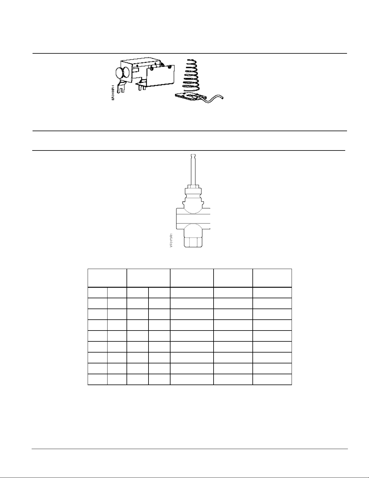
Accessories
Figure 1. Packing Heating Element for
Use With SKD Actuators.
599-00417 Packing heating element.
The heater allows the stem to move freely
in valves that control fluids at temperatures
below 32°F (0°C). It reduces ice crystal
formation on the stem that can damage the
packing.
Operating Voltage 24 Vac
Heating Output 20 W
Page 2 Siemens Industry, Inc.
Flowrite 599 Series Three-Way Valves Technical Instructions
1
(0.85)
1/2
(15)
1.6
(1.37)
1/2
(15)
2.5
(2.15)
1/2
(15)
4
(3.44)
1/2
(15)
6.3
(5.43)
3/4
(20)
10
(8.6) 1 (25)
16
(13.8)
1-1/4
(32)
25
(21.5)
1-1/2
(40)
40
(34.4)
2
(50)
Document Number 155-185P25
June 10, 2014
Accessories,
Continued
Service Kits
599-00418: The packing heating element.
The heater allows the stem to move freely
in valves that control fluids at temperatures
below 32°F (0°C). It prevents ice crystal
formation on the stem that can damage the
packing.
Figure 2. Packing Heating Element for
Use With SKB/C and 8-inch Actuators.
Operating Voltage 24 Vac
Heating Output 20 W
Valve packing kit 599-03390
Rebuild/repack kits See Table 10.
Table 1. Female NPT x Female
NPT (F×F) 3-Way Valves.
Flow Rate
C
v
(Kvs)
Line Size
Inch (mm)
Connection
Stainless
Steel Trim
Bronze Trim
FxF 599-03144 599-03198
FxF 599-03145 599-03199
FxF 599-03146 599-03200
FxF 599-03147 599-03201
FxF 599-03148 599-03202
FxF 599-03149 599-03203
FxF 599-03150 599-03204
FxF 599-03151 599-03205
FxF 599-03152 599-03206
Siemens Industry, Inc. Page 3
Technical Instructions Flowrite 599 Series Three-Way Valves
Valve
Inches
Pressure Differential - psi
Cv\1 2 3 4 5 6 8
10
15
20
25
30
40
50
60
75
Valve
mm
Pressure Differential - kPa
1
10
20
30
40
50
60
80
Kvs/
150
200
300
400
500
Body
Temperature
Pressure
psig (kPa)
°F °C
ANSI Class 250
Bronze
-20 to +150 (-30 to 66)
+350 (177)
400 (2758)
300 (2068)
Document Number 155-185P25
June 10, 2014
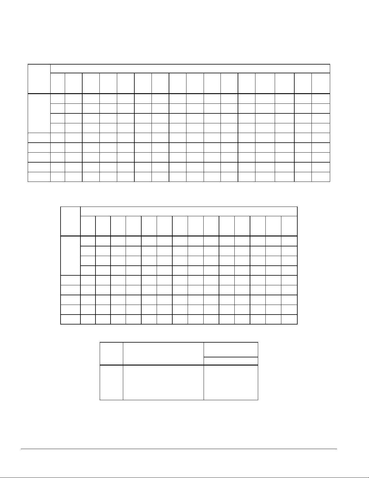
Table 2. Maximum Water Capacity - U.S. Gallons per Minute.
Size
in
1.0 1.4 1.7 2.0 2.2 2.5 2.8 3.2 3.9 4.5 5.0 5.5 6.3 7.1 7.8 8.7
1.6 2.3 2.8 3.2 3.6 3.9 4.5 5.1 6.2 7.2 8.0 8.8 10.1 11.3 12.4 13.9
1/2
2.5 3.5 4.3 5.0 5.6 6.1 7.1 7.9 97 11.2 12.5 13.7 15.8 17.7 19.4 22
4 5.7 7 8.0 8.9 10 11.3 12.6 15.5 17.9 20.0 21.9 25 28 31 35
3/4 6 8.9 10.9 12.6 14.1 15.4 17.8 20 24 28 32 35 40 45 49 55
1 10 14.1 17.3 20 22 24 28 32 39 45 50 55 63 71 77 87
1-1/4 16 23 28 32 36 39 45 51 62 72 80 88 101 113 124 139
1-1/2 25 35 43 50 56 61 71 79 97 112 125 137 158 177 194 217
2 40 57 69 80 89 98 113 126 155 179 200 219 253 283 310 346
3
Table 3. Maximum Water Capacity - Cubic Meters per Hour (m
/hr).
Size
in
100
0.09 0.3 0.4 0.5 0.5 0.6 0.7 0.8 0.9 1.0 1.2 1.5 1.7 1.9
0.14 0.4 0.6 0.8 0.9 1.0 1.1 1.2 1.4 1.7 1.9 2.4 2.7 3.1
15
0.2 0.7 1.0 1.2 1.4 1.5 1.7 1.9 2.2 2.6 3.0 3.7 4.3 4.8
0.3 1.1 1.5 1.9 2.2 2.4 2.7 3.1 3.4 4.2 4.9 6.0 6.9 7.7
20 0.5 1.7 2.4 3.0 3.4 3.8 4.2 4.9 5.4 6.7 7.7 9.4 10.9 12.1
25 0.9 2.7 3.8 4.7 5.4 6.1 6.7 7.7 8.6 10.5 12.2 14.9 17.2 19.2
32 1.4 4.4 6.2 7.6 8.7 9.8 10.7 12.3 13.8 16.9 19.5 23.9 27.6 30.9
40 2.2 6.8 9.6 11.8 13.6 15.2 16.7 19.2 22 26 30 37 43 48
50 3.4 10.9 15.4 18.8 22 24 27 31 34 42 49 60 69 77
Table 4. Body Temperature-Pressure Rating.
Valve
+200 (93)
+250 (121)
+300 (149)
385 (2655)
365 (2586)
335 (2300)
Page 4 Siemens Industry, Inc.
 Loading...