

Siemens 599-02001, 599-02016, 599-02000, 599-02017, 599-02018 Technical Instructions
...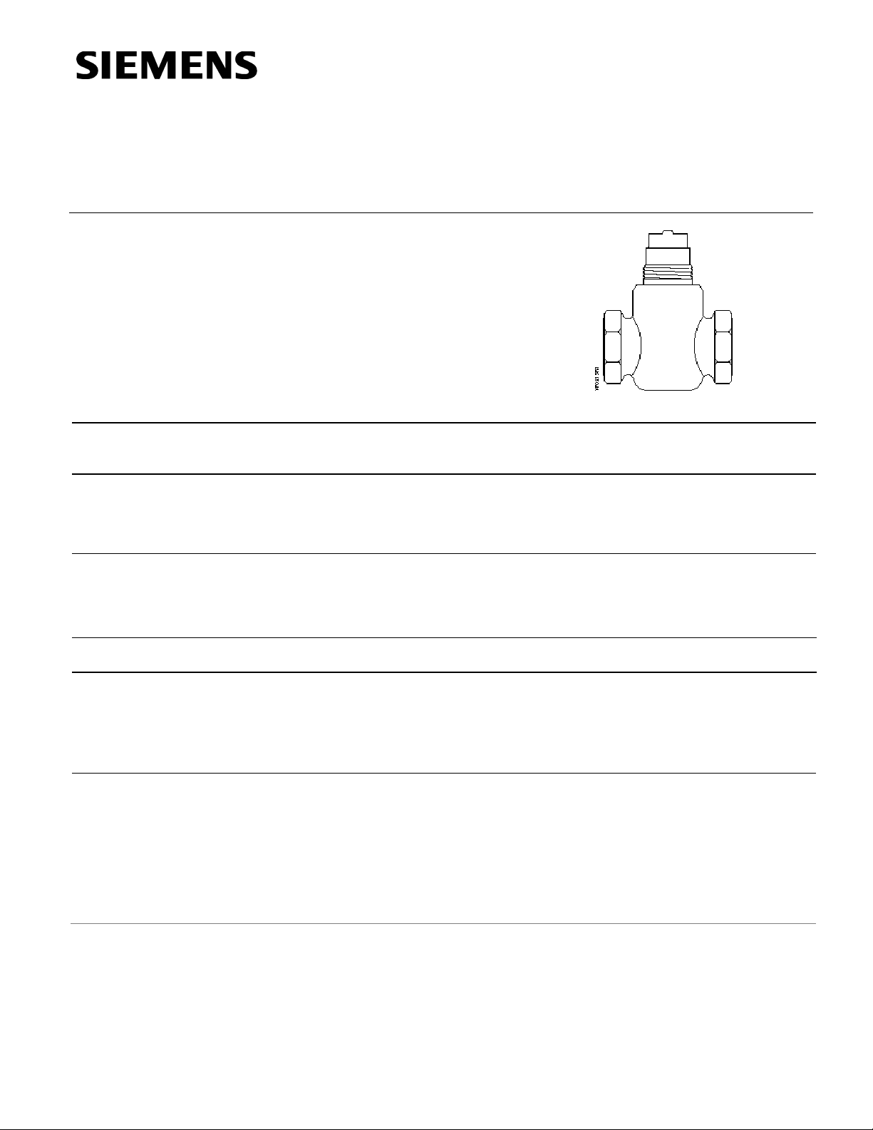
Powermite 599 Series
MT Series Terminal Unit
Two-way Valves
Technical Instructions
Document No. 155-196P25
VF 599-5
April 9, 2009
Description
Features
Application
Product Numbers
Ordering a Valve
Plus Actuator
Assembly
Specifications
The Powermite 599 Series ANSI Class 250 MT Series two-way valve bodies work with
any MT Series pneumatic or electronic actuator with a 7/32-inch (5.5 mm) stroke.
• Direct coupled universal bonnet
• Choice of brass or stainless steel trim
• ANSI Leakage Class IV (0.01% of Cv)
A typical application for the Powermite two-way valve is the control of hot or chilled
water or low pressure (<15 psi with stainless steel trim only) steam for convectors, fan
coil units, unit conditioners, radiation, reheat coils, and similar terminal units requiring
an actuator that delivers a minimum of 67 pounds force (300 N).
See Table 2.
To order a complete valve plus actuator assembly from the factory, combine the
actuator prefix code with the suffix of the valve assembly product number. See
Technical Bulletin TB251 (155-306P25) for selection procedure and ordering codes.
Valve assemblies can be ordered using the numbers in Table 2.
Valve size 1/2 inch to 1 inch (15 mm to 25 mm)
Capacity See Tables 3 through 6 and Figure 1
Body style Globe
Seat style Metal-to-metal
Action Normally open/normally closed
Valve body rating ANSI Class 250; See Table 1
Stem travel (Stroke) 7/32-inch (5.5 mm)
Siemens Building Technologies, Inc.
Technical Instructions Powermite 599 MT Series Terminal Unit 2-way Valves
Document Number 155-196P25
April 9, 2009
Specifications
Material
Body UNS CA 844 bronze or
forged brass C37700
Body trim See Table 2
Stem Stainless steel ASTM A582 Type 303
Packing Ethylene propylene O-ring
Operating
Spring Range
Normally closed 10 to 15 psi (69 to 102 kPa)
Normally open 3 to 8 psi (21 to 55 kPa)
Controlled medium Water, low pressure steam
(<15psi with stainless steel trim only),
water-glycol solutions to 50%
Medium temperature range 35°F to 250°F (2°C to 120°C)
Maximum inlet pressure See Table 1
Maximum recommended differential pressure for modulating service
Liquid
Steam
Rangeability Cv <1 >50:1
Brass trim Stainless steel trim
25 psi (173 kPa) 50 psi (345 kPa)
— 15 psi (103 kPa)
Cv >1 >100:1
Close-off pressures See Tables 7 and 8 and Figure 2
Close-off ratings According to ANSI/FCI 70-2
Leakage rate Class IV (0.01% of Cv)
Flow characteristics Modified equal percentage
Miscellaneous
Canadian Registration Numbers 0H7645.5
0C0838.9
Mounting location NEMA 1 (interior only)
Dimensions See Tables 10 and 11 and Figure 4
Valve Weight See Table 11
Service Kit
Sealing rings for union valves (package of 25)
1/2-inch (15 mm) 698-088
3/4-inch (20 mm) 599-03394
Union connection kit
1/2-inch (15 mm) 599-02941
3/4-inch (20 mm) 599-02942
Protective black knob
426888950
to cover the bonnet
and threads/manual
override.
VF0288R1
Page 2 Siemens Building Technologies, Inc.

Powermite 599 MT Series Terminal Unit 2-way Valves Technical Instructions
Document Number 155-196P25
April 9, 2009
Table 1. Body Temperature-Pressure Rating.
Temperature Pressure
Valve Body
°F °C psig (kPa)
-20 to 150 (-30 to 66) 400 (2758)
Bronze/
Forged Brass
200 (93) 385 (2655)
250 (121) 365 (2586)
300 (149) 335 (2300)
350 (177) 300 (2068)
VF0215R1
Female NPT x Female NPT
FxF
Flow Rate
Action
Cv (Kvs) Inch (mm)
0.4 (0.34) 1/2 (15) 599-02015 599-02016 — 599-02000 599-02001 —
0.63 (0.54) 1/2
1.0 (0.85) 1/2
1.6 (1.37) 1/2
2.5 (2.15) 1/2
4.0 (3.44) 1/2
Normally Closed
6.3 (5.43) 3/4 (20) 599-02027 599-02028 — 599-02012 599-02013 —
10 (8.6) 1 (25) 599-02029
0.4 (0.34) 1/2 (15) 599-02047 599-02048 — 599-02030 599-02031 —
0.63 (0.54) 1/2
1.0 (0.85) 1/2
1.6 (1.37) 1/2
2.5 (2.15) 1/2
4.0 (3.44) 1/2
Normally Open
6.3 (5.43) 3/4 (20) 599-02061 599-02062
10 (8.6) 1 (25) 599-02063
Nominal Valve
Size
(15)
(15)
(15)
(15)
(15)
(15)
(15)
(15)
(15)
(15)
VF0210R1
Female NPT x Union Male
FxUM
VF0217R1
Angle Female x Union Male
AFxUM
Table 2. Product Part Numbers.
Trim and Connection
Stainless Steel Brass
F×F F×UM AF×UM F×F F×UM AF×UM
599-02017 599-02018 — 599-02002 599-02003 —
599-02019 599-02020 — 599-02004 599-02005 —
599-02021 599-02022 — 599-02006 599-02007 —
599-02023 599-02024 — 599-02008 599-02009 —
599-02025 599-02026 — 599-02010 599-02011 —
—
599-02049 599-02050
599-02051 599-02052
599-02053 599-02054
599-02055 599-02056 599-02057 599-02038 599-02039 599-02040
599-02058 599-02059 599-02060 599-02041 599-02042 599-02043
—
— 599-02014 — —
—
—
—
—
—
599-02032 599-02033 —
599-02034 599-02035 —
599-02036 599-02037 —
599-02044 599-02045 —
599-02046 — —
Siemens Building Technologies, Inc. Page 3

Technical Instructions Powermite 599 MT Series Terminal Unit 2-way Valves
Document Number 155-196P25
April 9, 2009
Table 3. Maximum Water Capacity - U.S. Gallons per Minute.
Valve
Size
In
inches
1/2
3/4
1
Pressure Differential - psi
Cv\1 2 3 4 5 6 8 10 15 20 25 30 40 50 60 75
0.4 0.6 0.7 0.8 0.9 1.0 1.1 1.3 1.5 1.8 2.0 2.2 2.5 2.8 3.1 3.5
0.63 0.9 1.1 1.3 1.4 1.5 1.8 2.0 2.4 2.8 3.2 3.5 4.0 4.5 4.9 5.5
1.0 1.4 1.7 2.0 2.2 2.5 2.8 3.2 3.9 4.5 5.0 5.5 6.3 7.1 7.8 8.7
1.6 2.3 2.8 3.2 3.6 3.9 4.5 5.1 6.2 7.2 8.0 8.8 10.1 11.3 12.4 13.9
2.5 3.5 4.3 5.0 5.6 6.1 7.1 7.9 9.7 11.2 12.5 13.7 15.8 17.7 19.4 22
4 5.7 7 8.0 8.9 10 11.3 12.6 15.5 17.9 20.0 21.9 25 28 31 35
6.3 8.9 10.9 12.6 14.1 15.4 17.8 20 24 28 32 35 40 45 49 55
10 14.1 17.3 20 22 24 28 32 39 45 50 55 63 71 77 87
3
Table 4. Maximum Water Capacity - Cubic Meters per Hour (m
/hr).
Valve Size Pressure Differential - kPa
In
mm
1 10 20 30 40 50 60 80
Kvs/
100
150 200 300 400 500
0.03 0.11 0.15 0.19 0.22 0.24 0.26 0.30 0.34 0.42 0.48 0.59 0.68 0.76
0.05 0.17 0.24 0.30 0.34 0.38 0.42 0.48 0.54 0.66 0.76 0.94 1.08 1.21
0.09 0.27 0.38 0.47 0.54 0.60 0.66 0.76 0.85 1.0 1.2 1.5 1.7 1.9
15
0.14 0.43 0.61 0.75 0.87 0.97 1.06 1.23 1.37 1.7 1.9 2.4 2.7 3.1
0.21 0.68 0.96 1.17 1.35 1.51 1.66 1.91 2.15 2.6 3.0 3.7 4.3 4.8
0.34 1.1 1.5 1.9 2.2 2.4 2.7 3.1 3.4 4.2 4.9 6.0 6.9 7.7
0.54 1.7 2.4 3.0 3.4 3.8 4.2 4.9 5.4 6.7 7.7 9.4 10.9 12.1
20
0.86 2.7 3.8 4.7 5.4 6.1 6.7 7.7 8.6 10.5 12.2 14.9 17.2 19.2
25
1.4 4.4 6.2 7.6 8.7 9.8 10.7 12.3 13.8 16.9 19.5 23.9 27.6 30.9
32
2.2 6.8 9.6 11.8 13.6 15.2 16.7 19.2 22 26 30 37 43 48
40
Page 4 Siemens Building Technologies, Inc.
 Loading...