

Siemens 599-01134, 599-01133, Powermite 599 Series, 599-01132, 599-01136 Technical Instructions
...Page 1
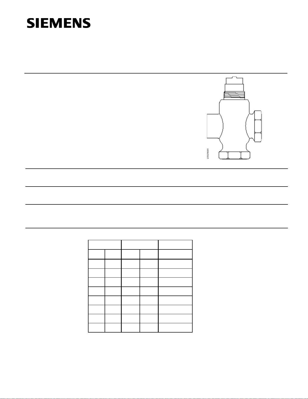
Powermite 599 Series
Technical Instructions
MZ Series Zone Control
Three-way Valves
Document No. 155-199P25
VF 599-8
October 24, 2005
Description
Features
Application
Product Numbers
The Powermite 599 Series ANSI Class 250 MZ Series three-way valves are designed to
work the SSB MZ Series actuator with a 7/32-inch (5.5 mm) stroke.
Direct coupled universal bonnet
ANSI Leakage Class IV (0.01% of Cv)
A typical application for the Powermite three-way valve is the mixing of hot or chilled
water for convectors, fan coil units, unit conditioners, radiation, reheat coils, and similar
terminal units requiring an actuator that delivers a minimum of 45 pounds force (200 N).
Table 1. Product Numbers.
Flow Rate Line Size Product
Cv (Kvs) inch (mm) Number
0.4 (0.34) 1/2 (15) 599-01132
0.63 (0.54) 1/2 (15) 599-01133
1 (0.85) 1/2 (15) 599-01134
1.6 (1.37) 1/2 (15) 599-01135
2.5 (2.15) 1/2 (15) 599-01136
4 (3.44) 1/2 (15) 599-01137
6.3 (5.43) 3/4 (20) 599-01138
10 (8.6) 1 (25) 599-01139
Siemens Industry, Inc.
Page 2
Technical Instructions
Line size 1/2 to 1 inch (15 to 25 mm)
Body UNS CA844 bronze
Canadian Registration Numbers 0H7645.5
Document No. 155-199P25
October 24, 2005
Ordering a Valve
Plus Actuator
Assembly
Specifications
Material
Operating
To order a complete valve plus actuator assembly from the factory, combine the
actuator prefix code with the suffix of the valve assembly product number. See
Technical Bulletin (TB) 252 (155-307P25) for selection procedure and ordering codes.
Valve assemblies can be ordered using the numbers in Table 1.
Capacity See Tables 3 and 4 and Figure 1
Body style Globe
Seat style Metal-to-metal
Action Three-way mixing
Valve body rating ANSI Class 250; See Table 2
Stem travel (Stroke) 7/32-inch (5.5 mm)
or forged brass C37700
Body trim Brass
Stem Stainless steel ASTM A582 Type 303
Packing Ethylene propylene O-ring
Controlled medium Water, glycol solutions to 50%
Medium temperature range 35°F to 250°F (2°C to 120°C)
Maximum inlet pressure See Table 2
Maximum recommended differential pressure
for modulating service 25 psi (173 kPa)
Rangeability
Cv <1 >50:1
Cv >1 >100:1
Close-off pressures See Table 5 and Figure 2
Close-off ratings According to ANSI/FCI 70-2
Leakage rate Class IV (0.01% of Cv)
Flow characteristics Linear
Miscellaneous
Service Kit
Page 2 Siemens Industry, Inc.
0C0838.9
Mounting location NEMA 1 (interior only)
Dimensions See Tables 6 and 7 and
Figures 4 and 5
Valve Weight See Table 6
Protective black knob
to cover the bonnet
and threads
4 268 8895 0
Page 3
Powermite 599 Series MZ Zone Control Three-way Valves Technical Instructions
Document No. 155-199P25
October 24, 2005
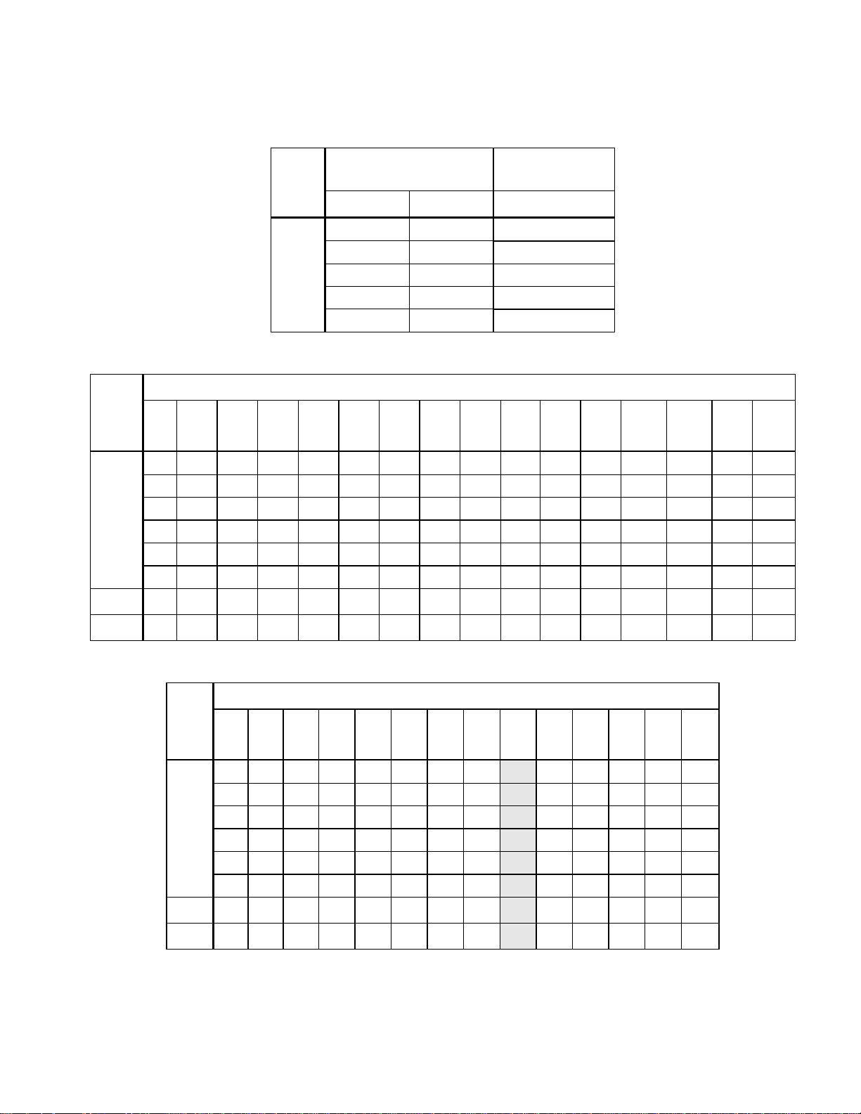
Table 2. Body Temperature-Pressure Rating.
Valve
Size
in
inches
1/2
3/4
Valve
Temperature
Pressure
psig (kPa)
Body
F° C° ANSI Class 250
-20 to +150 (-30 to 66) 400 (2758)
+200 (93) 385 (2655)
+250 (121) 365 (2586)
Bronze or
+300 (149) 335 (2300)
Forged Brass
+350 (177) 300 (2068)
Table 3. Maximum Water Capacity - U.S. Gallons per Minute.
Pressure Differential - psi
Cv\1 2 3 4 5 6 8 10 15 20 25 30 40 50 60 75
0.4 0.6 0.7 0.8 0.9 1.0 1.1 1.3 1.5 1.8 2.0 2.2 2.5 2.8 3.1 3.5
0.63 0.9 1.1 1.3 1.4 1.5 1.8 2.0 2.4 2.8 3.2 3.5 4.0 4.5 4.9 5.5
1.0 1.4 1.7 2.0 2.2 2.5 2.8 3.2 3.9 4.5 5.0 5.5 6.3 7.1 7.8 8.7
1.6 2.3 2.8 3.2 3.6 3.9 4.5 5.1 6.2 7.2 8.0 8.8 10.1 11.3 12.4 13.9
2.5 3.5 4.3 5.0 5.6 6.1 7.1 7.9 9.7 11.2 12.5 13.7 15.8 17.7 19.4 22
4 5.7 7 8.0 8.9 10 11.3 12.6 15.5 17.9 20.0 21.9 25 28 31 35
6.3 8.9 10.9 12.6 14.1 15.4 17.8 20 24 28 32 35 40 45 49 55
10 14.1 17.3 20 22 24 28 32 39 45 50 55 63 71 77 87
1
3
/hr).
Valve
Table 4. Maximum Water Capacity - Cubic Meters per Hour (m
Pressure Differential - kPa
Size
in
mm
1 10 20 30 40 50 60 80
Kvs/
150 200 300 400 500
100
0.03 0.11 0.15 0.19 0.22 0.24 0.26 0.30 0.34 0.42 0.48 0.59 0.68 0.76
0.05 0.17 0.24 0.30 0.34 0.38 0.42 0.48 0.54 0.66 0.76 0.94 1.08 1.21
0.09 0.27 0.38 0.47 0.54 0.60 0.66 0.76 0.85 1.0 1.2 1.5 1.7 1.9
15
0.14 0.43 0.61 0.75 0.87 0.97 1.06 1.23 1.37 1.7 1.9 2.4 2.7 3.1
0.21 0.68 0.96 1.17 1.35 1.51 1.66 1.91 2.15 2.6 3.0 3.7 4.3 4.8
0.34 1.1 1.5 1.9 2.2 2.4 2.7 3.1 3.4 4.2 4.9 6.0 6.9 7.7
0.54 1.7 2.4 3.0 3.4 3.8 4.2 4.9 5.4 6.7 7.7 9.4 10.9 12.1
20
0.86 2.7 3.8 4.7 5.4 6.1 6.7 7.7 8.6 10.5 12.2 14.9 17.2 19.2
25
Siemens Industry, Inc. Page 3
Page 4
Technical Instructions
Document No. 155-199P25
October 24, 2005
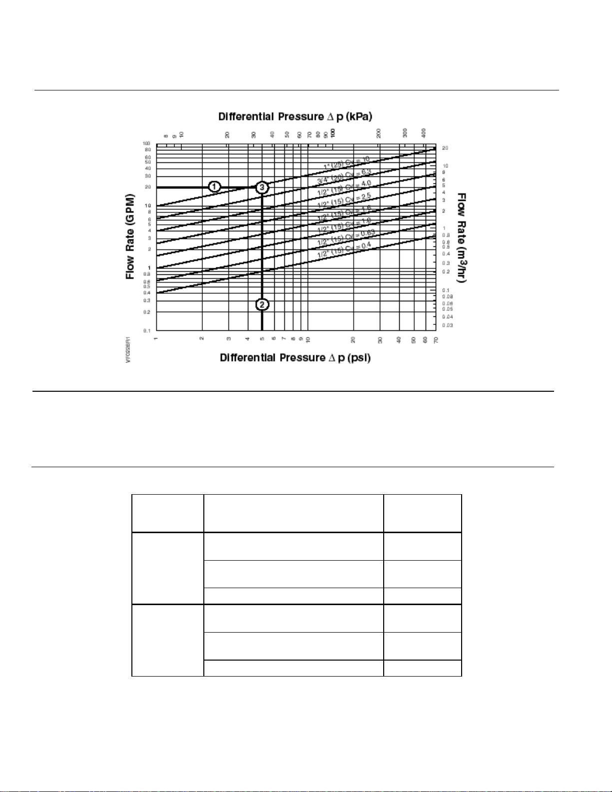
Selection Example
See Figure 1.
Figure 1. Water Capacity Graph.
Select a valve given:
Required flow = 20 gpm.
Desired pressure drop = 5 psi.
Choose a 1-inch (25 mm) valve, Cv 10.
Table 5. Close-off Pressures.
Action Valve Size Inches (mm)
1/2", 0.4< Cv <1.6
NC
Upper port
NO
Bottom port
(15 mm, 0.34< Kvs <1.37)
1/2", 2.5< Cv <4
(15 mm, 2.15< Kvs <3.44)
3/4" and 1" (20 mm and 25 mm) 30 (207)
1/2", 0.4< Cv <1.6
(15 mm, 0.34< Kvs <1.37)
1/2", 2.5< Cv <4
(15 mm, 2.15< Kvs <3.44)
3/4" and 1" (20 mm and 25 mm) 10 (69)
SSB Actuator
psi (kPa)
70 (483)
40 (276)
25 (172)
15 (103)
Page 4 Siemens Industry, Inc.
Page 5
Powermite 599 Series MZ Zone Control Three-way Valves Technical Instructions
Document No. 155-199P25
October 24, 2005
Operation
Sizing
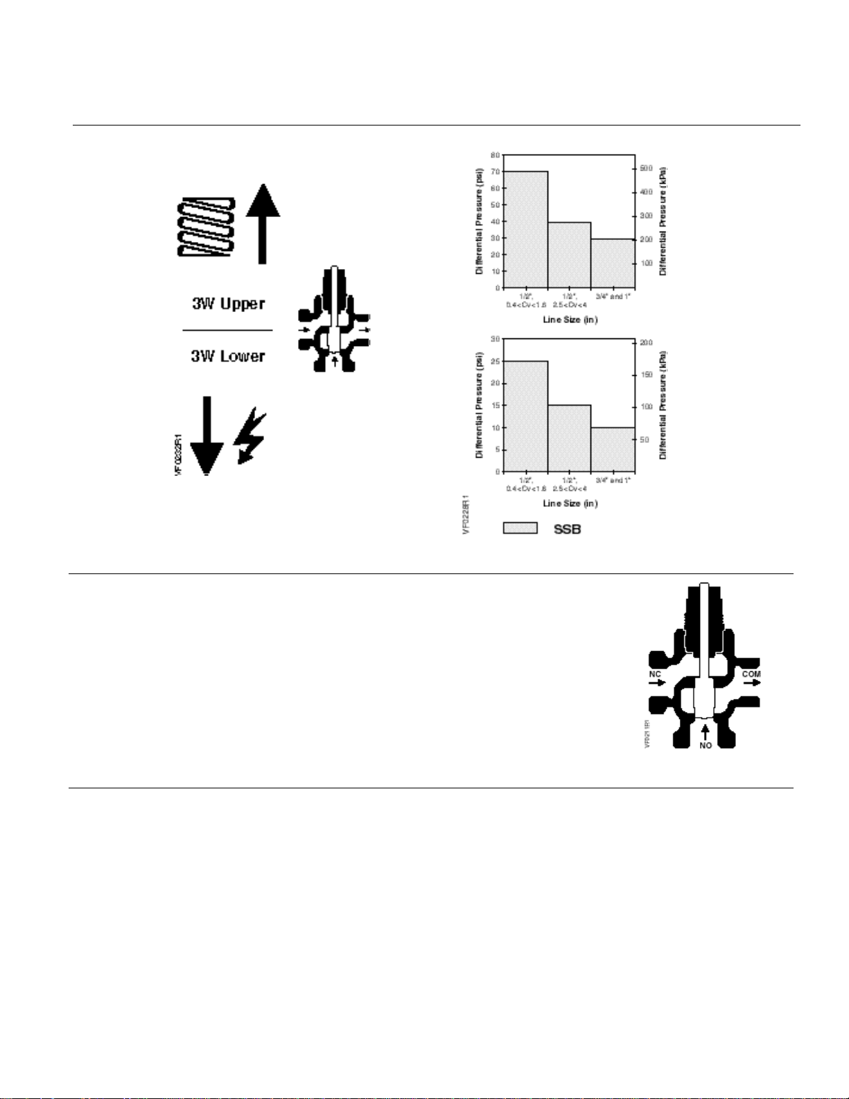
Figure 2. Close-off Pressures.
As the valve stem moves downward, the flow through the
NO port decreases and the flow through the NC port
increases. As the valve stem moves upward, the flow
through the NO port increases and the flow through the
NC port decreases.
In the event of power failure, a fail-safe actuator returns
the valve to its normal position. Fail-in-place actuators will
hold the last commanded position. See the Technical
Instructions of the various actuators for additional
information.
Figure 3.
The sizing of a valve is important for correct system operation. An undersized valve will
not have sufficient capacity at maximum load. An oversized valve can initiate cycling,
and the seat and throttling plug can be damaged because of the restricted opening.
Correct sizing of the control valve for actual expected conditions is considered essential
for good control.
The following variables must be determined:
• The medium to be controlled: water, etc.
• The maximum inlet temperature and pressure of the medium at the valve.
• The pressure differential that will exist across the valve under maximum load
demand.
Siemens Industry, Inc. Page 5
Page 6
Technical Instructions
Document No. 155-199P25
October 24, 2005
Sizing, Continued
Mounting and
Installation
Service
Dimensions
• The maximum capacity the valve must deliver.
• The maximum line pressure differential the valve actuator must close against.
See Application Bulletin (AB)-1 Control Valve Selection and Sizing (155-285) for further
recommendations.
See Tables 3 and 4 for valve capacities.
Install the valve so that the flow follows the direction of the arrow indicated on the valve
body.
For best performance, install the valve assembly with the actuator above the valve body.
The valve and actuator can be installed in any position between vertical and horizontal.
It is not recommended to install the valve assembly so that the actuator is below
horizontal or up side down.
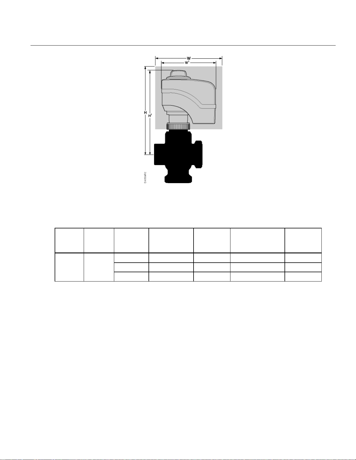
Allow sufficient space for servicing the valve and actuator. See Table 6 for valve body
dimensions. See Figure 5 and Table 7 for dimensions of the service envelope
recommended around the actuator.
NOTE: Instructions for field mounting an actuator, wiring diagrams, and start-up
are covered in the Technical Instructions and Installation Instructions for
each actuator.
Replace the valve if inoperable.
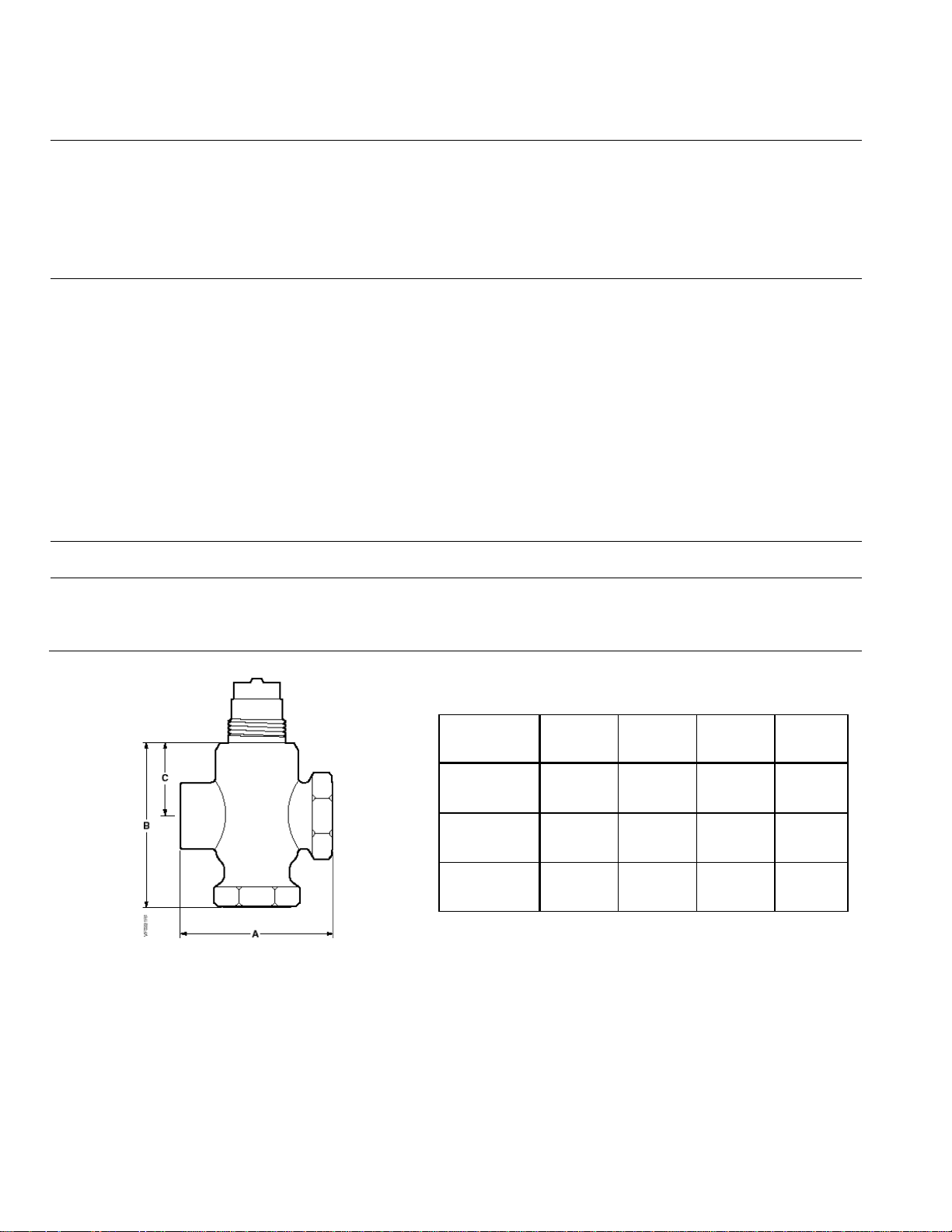
See Table 6 for valve body dimensions. The letters in Figure 5 refer to the valve
centerline to top of actuator, the actuator width, and service envelope dimensions in
Table 7.
Table 6. Three-way Valve Dimensions.
Figure 4. Three-way Valve.
Valve Size
inch (mm)
1/2
(15)
3/4
(20)
1
(25)
A B C
2-3/4
(70)
3-1/4
(83)
3-7/8
(98)
2-15/16
(74)
3-9/16
(90)
3-15/16
(99)
1-5/16
(33)
1-5/16
(33)
1-9/16
(39)
Weight
lb (kg)
1.10
(0.5)
1.44
(.65)
2.20
(1.0)
Page 6 Siemens Industry, Inc.
Page 7
Powermite 599 Series MZ Zone Control Three-way Valves Technical Instructions
Document No. 155-199P25
October 24, 2005
Figure 5.
Table 7. Dimensions of the Actuator and Recommended Service Envelope.
Dimensions in Inches (Millimeters).
Actuator
SSB
Actuator
Prefix
Code
254
255
Valve
line Size
Center line to
Top of
Actuator, H1
Service
Height
H
Actual width of
the Actuator
W1
Service
Width
W
1/2 (15) 4-7/8 (124) 13-1/8 (330) 3-1/4 (83) 11-1/4 (282)
3/4 (20) 4-7/8 (124) 13-1/8 (330) 3-1/4 (83) 11-1/4 (282)
1 (25) 5-1/8 (130) 13-3/8 (335) 3-1/4 (83) 11-1/4 (282)
Siemens Industry, Inc. Page 7
Page 8
Technical Instructions
Siemens Industry, Inc.
+ 1 847-215-1000
Your feedback is im port ant to us. If you have
Document No. 155-199P25
Document No. 155-199P25
October 24, 2005
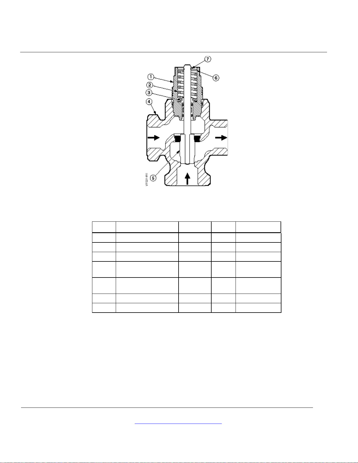
Parts Of The Valve
Table 8. Three-way Bronze/Forged Brass Valves.
Item Part Name Part No. Q’ty Material
1 Bonnet Ass’y — 1 —
2 Spring — 1 Stainless steel
3 Wiper — 1 Nylon
4 Valve Body — 1 Bronze or
Forged Brass
5 Stem and Plug
Assembly
— 1 Stainless steel
or brass
6 Upper guide disc — 1 Brass
7 Retaining ring — 1 Stainless steel
Information in this publication is based on current specifications. The company reserves the right to make changes in spec i fications and m odel s as
design improvements are introduced. Other product or com pany names mentioned herein may be the trademarks of t hei r respective owners.
© 2005 Siemens Industry, Inc.
Building Technologies Divis i on
1000 Deerfield Parkway
Buffalo Grove, IL 60089
comments about this document, please send them
to [email protected]
Printed in the USA
Page 8
 Loading...