

Siemens 599-01134, 599-01133, Powermite 599 Series, 599-01132, 599-01136 Technical Instructions
...
Powermite 599 Series
Technical Instructions
MZ Series Zone Control
Three-way Valves
Document No. 155-199P25
VF 599-8
October 24, 2005
Description
Features
Application
Product Numbers
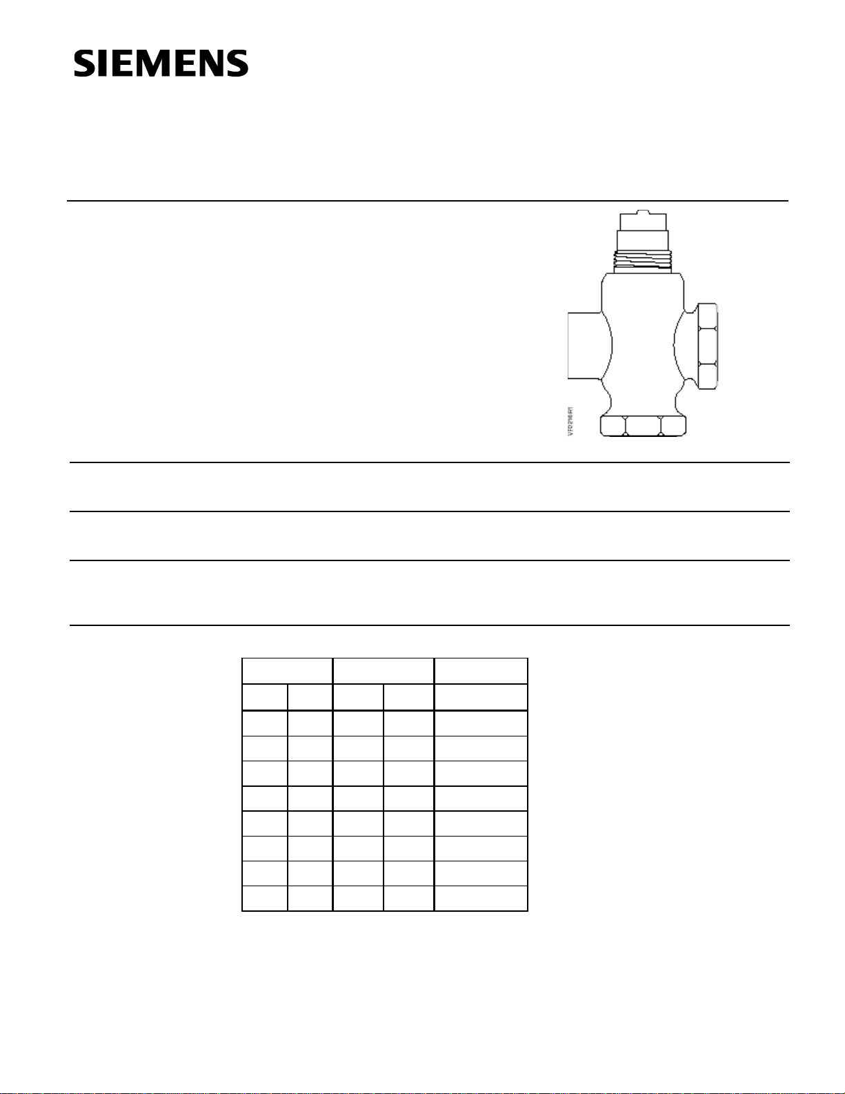
The Powermite 599 Series ANSI Class 250 MZ Series three-way valves are designed to
work the SSB MZ Series actuator with a 7/32-inch (5.5 mm) stroke.
Direct coupled universal bonnet
ANSI Leakage Class IV (0.01% of Cv)
A typical application for the Powermite three-way valve is the mixing of hot or chilled
water for convectors, fan coil units, unit conditioners, radiation, reheat coils, and similar
terminal units requiring an actuator that delivers a minimum of 45 pounds force (200 N).
Table 1. Product Numbers.
Flow Rate Line Size Product
Cv (Kvs) inch (mm) Number
0.4 (0.34) 1/2 (15) 599-01132
0.63 (0.54) 1/2 (15) 599-01133
1 (0.85) 1/2 (15) 599-01134
1.6 (1.37) 1/2 (15) 599-01135
2.5 (2.15) 1/2 (15) 599-01136
4 (3.44) 1/2 (15) 599-01137
6.3 (5.43) 3/4 (20) 599-01138
10 (8.6) 1 (25) 599-01139
Siemens Industry, Inc.

Technical Instructions
Line size 1/2 to 1 inch (15 to 25 mm)
Body UNS CA844 bronze
Canadian Registration Numbers 0H7645.5
Document No. 155-199P25
October 24, 2005
Ordering a Valve
Plus Actuator
Assembly
Specifications
Material
Operating
To order a complete valve plus actuator assembly from the factory, combine the
actuator prefix code with the suffix of the valve assembly product number. See
Technical Bulletin (TB) 252 (155-307P25) for selection procedure and ordering codes.
Valve assemblies can be ordered using the numbers in Table 1.
Capacity See Tables 3 and 4 and Figure 1
Body style Globe
Seat style Metal-to-metal
Action Three-way mixing
Valve body rating ANSI Class 250; See Table 2
Stem travel (Stroke) 7/32-inch (5.5 mm)
or forged brass C37700
Body trim Brass
Stem Stainless steel ASTM A582 Type 303
Packing Ethylene propylene O-ring
Controlled medium Water, glycol solutions to 50%
Medium temperature range 35°F to 250°F (2°C to 120°C)
Maximum inlet pressure See Table 2
Maximum recommended differential pressure
for modulating service 25 psi (173 kPa)
Rangeability
Cv <1 >50:1
Cv >1 >100:1
Close-off pressures See Table 5 and Figure 2
Close-off ratings According to ANSI/FCI 70-2
Leakage rate Class IV (0.01% of Cv)
Flow characteristics Linear
Miscellaneous
Service Kit
Page 2 Siemens Industry, Inc.
0C0838.9
Mounting location NEMA 1 (interior only)
Dimensions See Tables 6 and 7 and
Figures 4 and 5
Valve Weight See Table 6
Protective black knob
to cover the bonnet
and threads
4 268 8895 0
Powermite 599 Series MZ Zone Control Three-way Valves Technical Instructions
Document No. 155-199P25
October 24, 2005
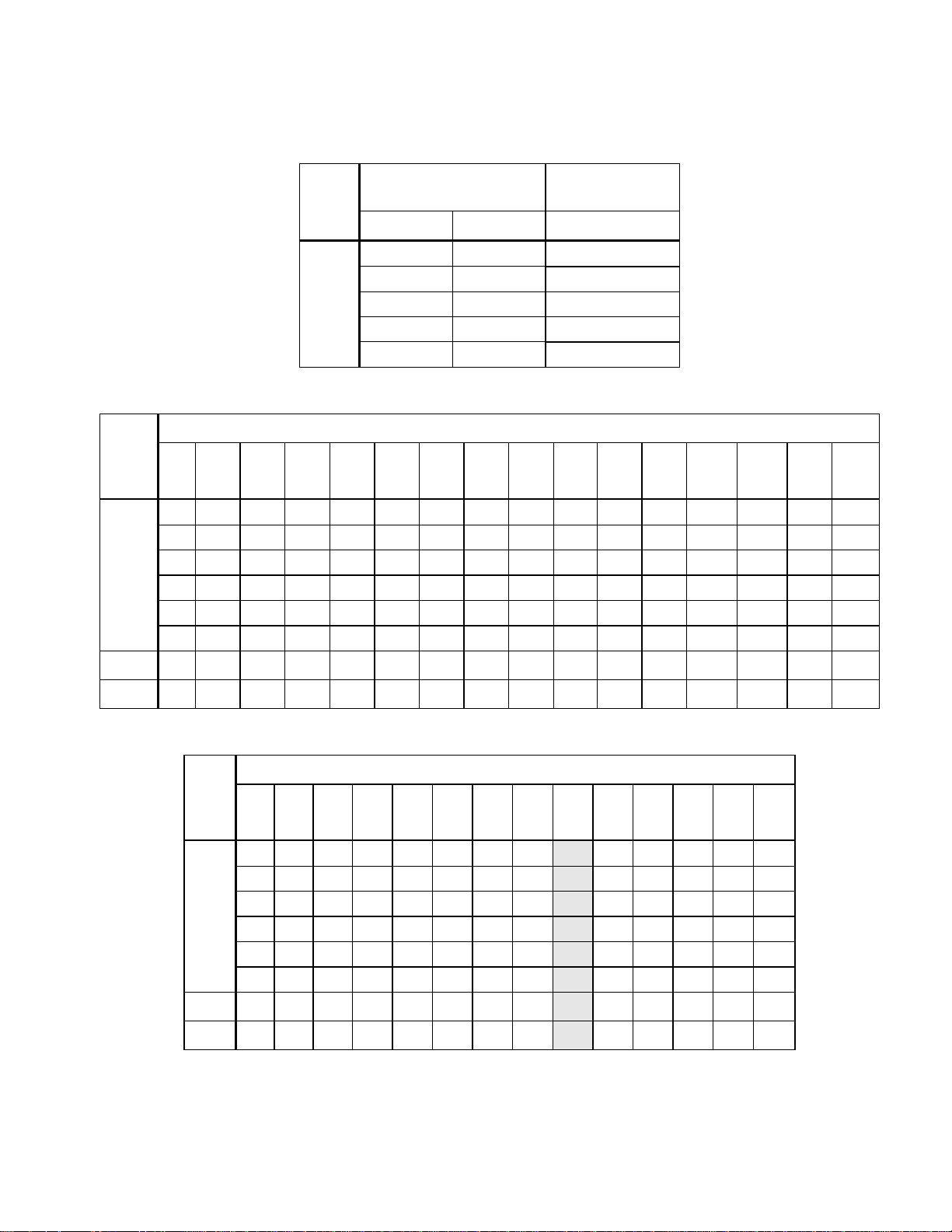
Table 2. Body Temperature-Pressure Rating.
Valve
Size
in
inches
1/2
3/4
Valve
Temperature
Pressure
psig (kPa)
Body
F° C° ANSI Class 250
-20 to +150 (-30 to 66) 400 (2758)
+200 (93) 385 (2655)
+250 (121) 365 (2586)
Bronze or
+300 (149) 335 (2300)
Forged Brass
+350 (177) 300 (2068)
Table 3. Maximum Water Capacity - U.S. Gallons per Minute.
Pressure Differential - psi
Cv\1 2 3 4 5 6 8 10 15 20 25 30 40 50 60 75
0.4 0.6 0.7 0.8 0.9 1.0 1.1 1.3 1.5 1.8 2.0 2.2 2.5 2.8 3.1 3.5
0.63 0.9 1.1 1.3 1.4 1.5 1.8 2.0 2.4 2.8 3.2 3.5 4.0 4.5 4.9 5.5
1.0 1.4 1.7 2.0 2.2 2.5 2.8 3.2 3.9 4.5 5.0 5.5 6.3 7.1 7.8 8.7
1.6 2.3 2.8 3.2 3.6 3.9 4.5 5.1 6.2 7.2 8.0 8.8 10.1 11.3 12.4 13.9
2.5 3.5 4.3 5.0 5.6 6.1 7.1 7.9 9.7 11.2 12.5 13.7 15.8 17.7 19.4 22
4 5.7 7 8.0 8.9 10 11.3 12.6 15.5 17.9 20.0 21.9 25 28 31 35
6.3 8.9 10.9 12.6 14.1 15.4 17.8 20 24 28 32 35 40 45 49 55
10 14.1 17.3 20 22 24 28 32 39 45 50 55 63 71 77 87
1
3
/hr).
Valve
Table 4. Maximum Water Capacity - Cubic Meters per Hour (m
Pressure Differential - kPa
Size
in
mm
1 10 20 30 40 50 60 80
Kvs/
150 200 300 400 500
100
0.03 0.11 0.15 0.19 0.22 0.24 0.26 0.30 0.34 0.42 0.48 0.59 0.68 0.76
0.05 0.17 0.24 0.30 0.34 0.38 0.42 0.48 0.54 0.66 0.76 0.94 1.08 1.21
0.09 0.27 0.38 0.47 0.54 0.60 0.66 0.76 0.85 1.0 1.2 1.5 1.7 1.9
15
0.14 0.43 0.61 0.75 0.87 0.97 1.06 1.23 1.37 1.7 1.9 2.4 2.7 3.1
0.21 0.68 0.96 1.17 1.35 1.51 1.66 1.91 2.15 2.6 3.0 3.7 4.3 4.8
0.34 1.1 1.5 1.9 2.2 2.4 2.7 3.1 3.4 4.2 4.9 6.0 6.9 7.7
0.54 1.7 2.4 3.0 3.4 3.8 4.2 4.9 5.4 6.7 7.7 9.4 10.9 12.1
20
0.86 2.7 3.8 4.7 5.4 6.1 6.7 7.7 8.6 10.5 12.2 14.9 17.2 19.2
25
Siemens Industry, Inc. Page 3
 Loading...