

Page 1
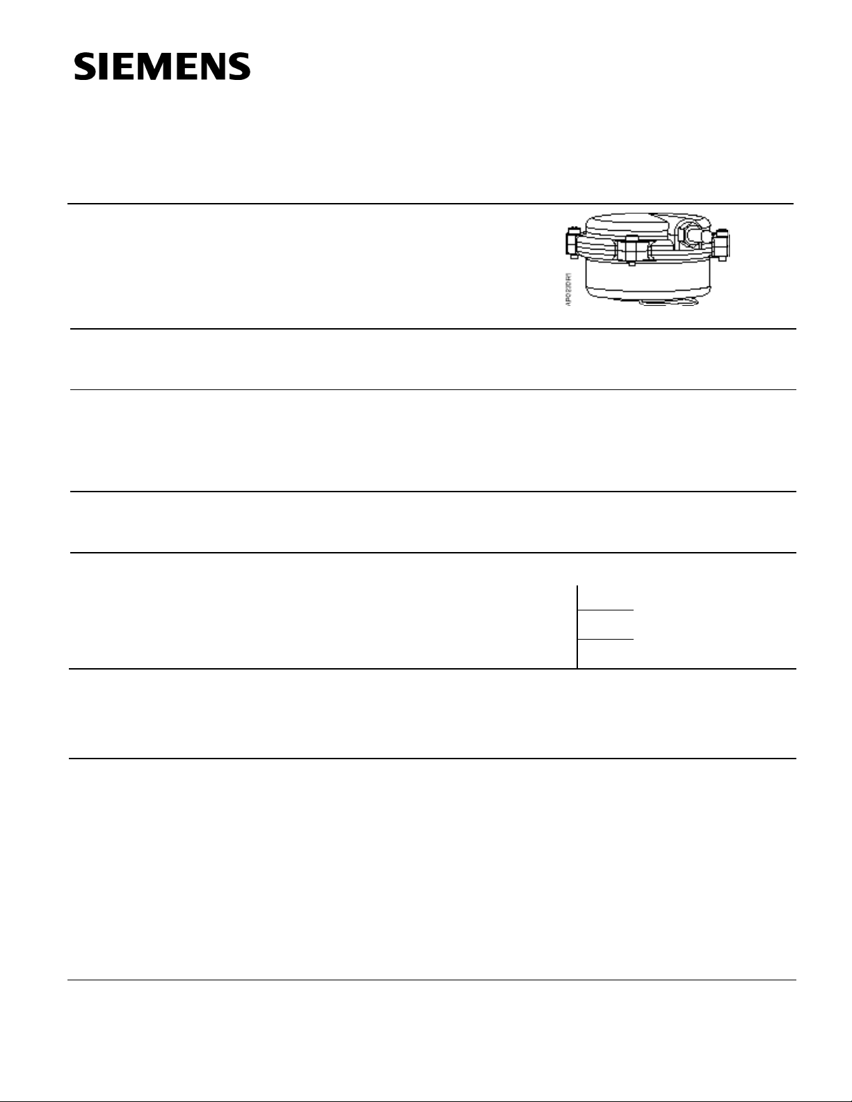
Powermite 599 Series
Technical Inst ruction
MT Series 2-inch Pn eumatic Valve
Actuator
Description
Document No. 155-189P25
AP 599-4
January 16, 2006
The Powermite 599 Series MT Series 2-inch pneumatic valve actuator is designed for
use with the Powermite 599 Series MT Series terminal unit valves with a 7/32-inch
(5.5 mm) stroke.
Features
Application
Product Number
10 to 15 psi spring range valve 256
Ordering
Information
Specifications
• Low profile
• Freely rotates to aid tubing installation
• Easy installation and removal
• All metal housing
These 2-inch pneumatic actuators are designed to be used on Powermite MT Series
terminal unit valves requiring a minimum of 67 pounds force (300N). They can be used
in liquid and steam service applications.
599 -01088
To order a complete valve plus actuator assembly from the factory, combine the
actuator prefix code with the suffix of the valve product number. See Technical Bulletin
(TB) 251 (155-306P25) for selection procedures.
To order an actuator only, use the product number listed above
Effective diaphragm area 3.4 inch
Diaphragm material Silicone
Nominal spring range Valve dependent
Span 5 psi (34 kPa) valve dependent
Nominal stroke 7/32-inch (5.5 mm)
Maximum diaphragm pressure 35 psi (241 kPa)
Air Connection 1/8” N.P.T. fitting for 1/4-inch OD
plastic tubing
Ambient temperature
Transportation -40 to 180°F (-40 to 82°C)
Operating 35 to 120°F (-2 to 49°C)
Actuator Prefix code when combining with a
3 to 8 psi spring range valve 257
8 to 13 spring range valve 258
2
(22 cm2)
Siemens Industry, Inc.
Page 2
Technical Instruction
Document No. 155-189P25
January 16, 2006
Specifications,
Continued
Mounting location NEMA 1 (interior only)
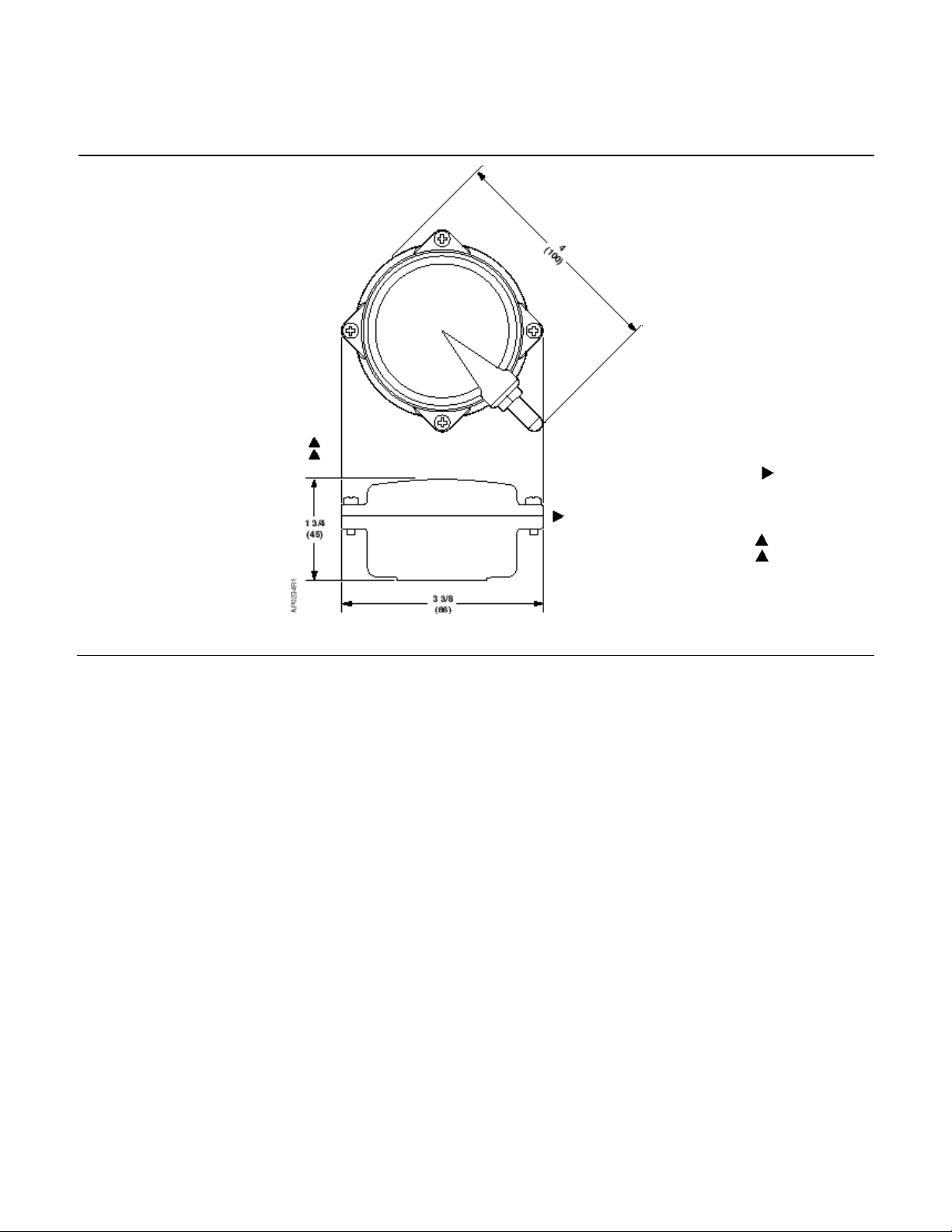
Dimensions See Figure 2
Weight 0.43 lb (0.2 kg)
Service Kit
Operation
Mounting and
Installation
Diaphragm replacement kit (Package of five) 656-736
The control air signal upon the diaphragm causes the valve to modulate whenever the
air pressure is within the spring range of the valve.
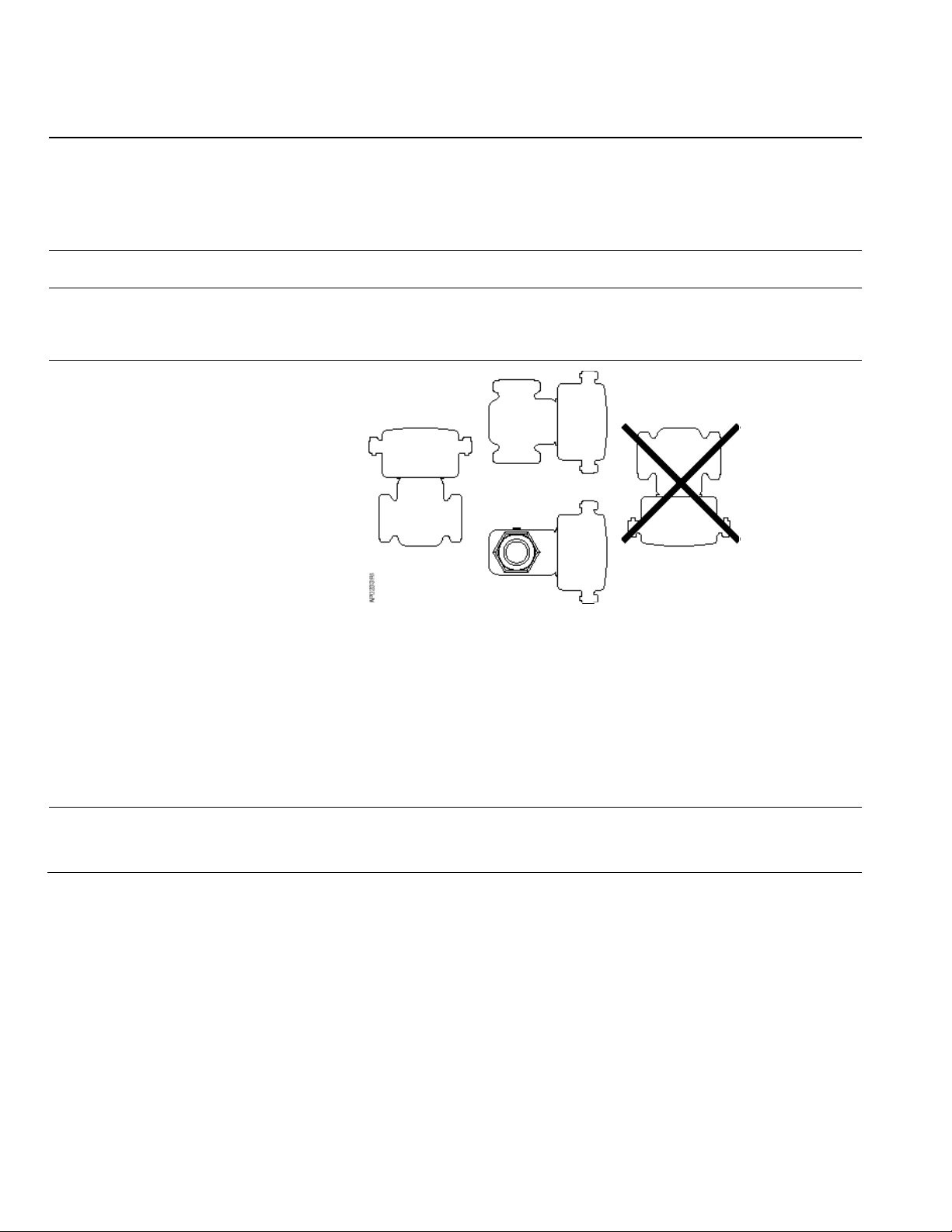
Figure 1. A cceptable Mounting Positions.
Allow 8 inches (200 mm) headroom and 6 inches (150 mm) on either side of the
actuator.
For best performance install the actuator vertically above the valve. The actuator can be
installed in any position between vertical and horizontal. We do not recommend
installing the actuator below horizontal or up side down. See Figure 1 for allowable
mounting positions.
Complete instructions for field mounting the actuator are included with the actuator.
Service
Page 2 Siemens Industry, Inc.
Diaphragm replacement
Complete instructions are included in the diaphragm replacement kit.
Page 3
Powermite 599 Series 2-inch Pneumatic Valve Actuator Technical Instruction
155-189P25
January 16, 2006
Dimensions
Minimum access space
recommended
6 inch (150 mm)
8 inch (200 mm)
Figure 2. Dimensions in inches. Millimeters in parentheses.
Siemens Industry, Inc. Page 3
Page 4
Technical Instruction
Siemens Industry, Inc.
+ 1 847-215-1000
Your feedback is im portant to us. If you have comments about this
Document No. 155-189P25
Actuator Details
Not
1/8” N.P.T. fitting for 1/4 OD plastic
1
Brass
Document No. 155-189P25
January 16, 2006
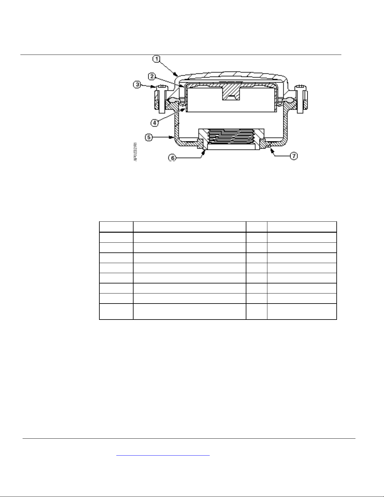
Figure 3. Powermite AP 599 Series 2-inch Pneumatic Valve Actuator.
Table 1. Parts of the Actuator. See Figure 3.
Item Description Q’ty Material
1 Upper housing 1 Aluminum
2 Diaphragm 1 Silicone
3 Thread forming screw 4 Zinc plated steel
4 Piston cup 1 Aluminum
5 Lower housing 1 Aluminum
6 Lower housing retaining nut 1 Brass
7 Retaining clip 1 Galvaniz ed steel
shown
tubing
Information in this publication is based on current specifications. The company reserves the right to m ake changes in specifi c ations and models as
design improvements are introduced. Product or company names mentioned herein may be the trademarks of their respective owners.
© 2006 Siemens Industry, I nc.
Building Technologies Divis i on
1000 Deerfield Parkway
Buffalo Grove, IL 60089
document, please send them to
Printed in the USA
Page 4
 Loading...