

Page 1
Powers™ Controls
RL 147 Positioning Relay
Technical Instructions
Document No. 155-038P25
RL 147-2
April 1, 2005
Description
Features
Product Numbers
Specifications
Operating
Physical
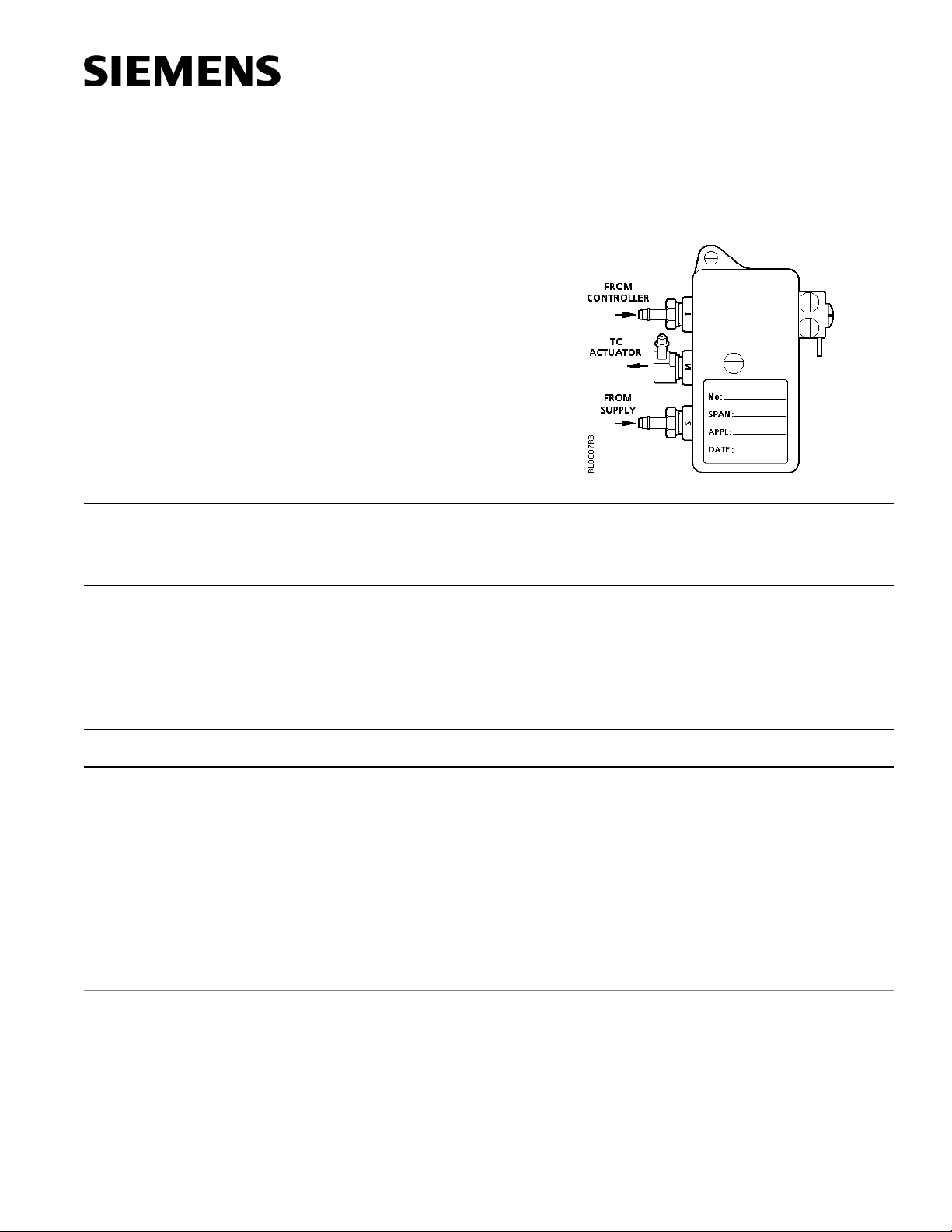
The RL 147 Positioning Relay is a compact, pneumatic device designed to provide
positive positioning of a pneumatic valve or damper actuator. The positioner provides
supply air pressure against the actuator diaphragm to initiate stem or shaft movement.
The actuator spring reverses the stem or shaft movement.
Rapid response
Good repeatability
Adjustable start point pressure
Adjustable span
Low air consumption
See Table 1.
Ambient Temperature Range
Storage -20 to 160°F (-29 to 71°C)
Operation 35 to 160°F (2 to 71°C)
Maximum Pilot Signal Pressure 30 psig (207 kPa)
Maximum Supply Air Pressure 60 psig (413 kPa)
Start Point Adjustment Range 3 to 10 psig (21 to 69 kPa)
Operating Span Adjustment Range 3 to 12 psig (21 to 83 kPa)
Response 1/10 psi Input change (0.7 kPa)
Air Capacity @ P = 2 psi (14 kPa) 410 scim (112 ml/s)
Air Consumption 40 scim (11 ml/s)
Air Connections 1/8-inch NPT
Body Materials Zinc
Cover Electro Plated Steel
Dimensions See Figure 14
Shipping Weight, with kit 2 lb (0.9 kg)
Siemens Industry, Inc.
Page 2
Technical Instructions RL 147 Positioning Relay
Document Number 155-038P25
April 1, 2005
Table 1. Product Numbers for Positioning Relay and Mounting Kits.
Description of Actuator Type
Product Numbers
Positioning Relay Mounting Kit
Reference
Page
No. 3 Damper Actuator For actuators manufactured after 1/1/93 147-2000 147-104 10
No. 4 Damper Actuator 147-2000 147-314 10
No. 6 Damper Actuator 147-2000 147-276 11
8-inch Valve Actuator 12
For VF 599 Series Flowrite actuators manufactured after 3/1/96
Contains both relay and mounting
599-00426
kit
For Model 3 Flowrite actuators manufactured between 3/1/93
147-2000 147-333 11
and 1/1/96
For Models 1 and 2 Flowrite actuators. Also order spring arm
147-2000 147-277 13
No. 147-307 for use with VF 591 5-inch and 6-inch balanced
valves
12-inch Valve Actuator 12
For VF 599 Series Flowrite actuators manufactured after 1/1/96
Contains both relay and mounting
599-00423
kit
For Flowrite actuators manufactured between 3/78 and 1/1/96 147-2000 147-311 14
For Super Flowrite and 12-inch Flowrite actuators
147-2000 147-279 13
manufactured before 3/78
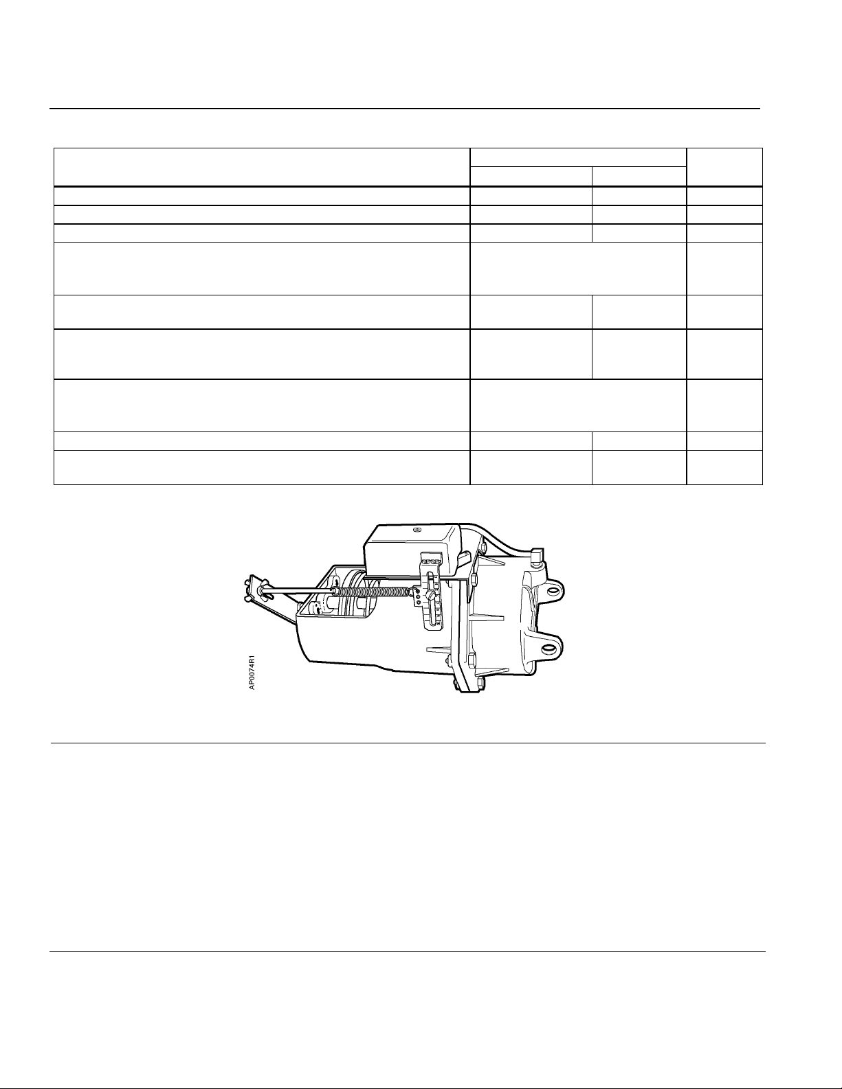
Figure 1. The RL 147 Positioning Relay Mounted on a No. 6 Damper Actuator.
Application
The Positioning Relay is recommended for damper actuator and valve applications
where rapid speed of response and/or repeatability of stem position is needed to
obtain good system operation. It can be used to reduce the span of controlled
devices to permit sequencing. It can also be used to increase the close-off force of a
normally open actuator without affecting its spring span, because the positioner
uses full supply air pressure to position the actuator.
The spring range of the actuator does not affect the operation of the positioner.
Therefore, it is recommended that an actuator with a high spring range, such as
8 psig to 13 psig (55 kPa to 90 kPa), be selected. This combination has the high
return force of the actuator spring, plus the high forward force available from the
positioner.
Page 2 Siemens Industry, Inc.
Page 3
RL 147 Positioning Relay Technical Instructions
Document Number 155-038P25
April 1, 2005
Application,
Continued
Operation
A positioning relay can be connected to handle up to four identical No. 6 damper
actuators or up to six identical No. 4 damper actuators if all actuators operate the same
damper, and no more than 100 feet of 1/4-inch (6.4 mm) OD tube is used to connect
them. All actuators connected this way must be identical (that is, same size, spring
range, stroke, etc.).
The positioning relay is single acting and is primarily intended for use on actuators with
an integral spring to return the actuator shaft to the normal position. Applications with a
double acting (springless) actuator require a reversing relay to provide the additional
control signal.
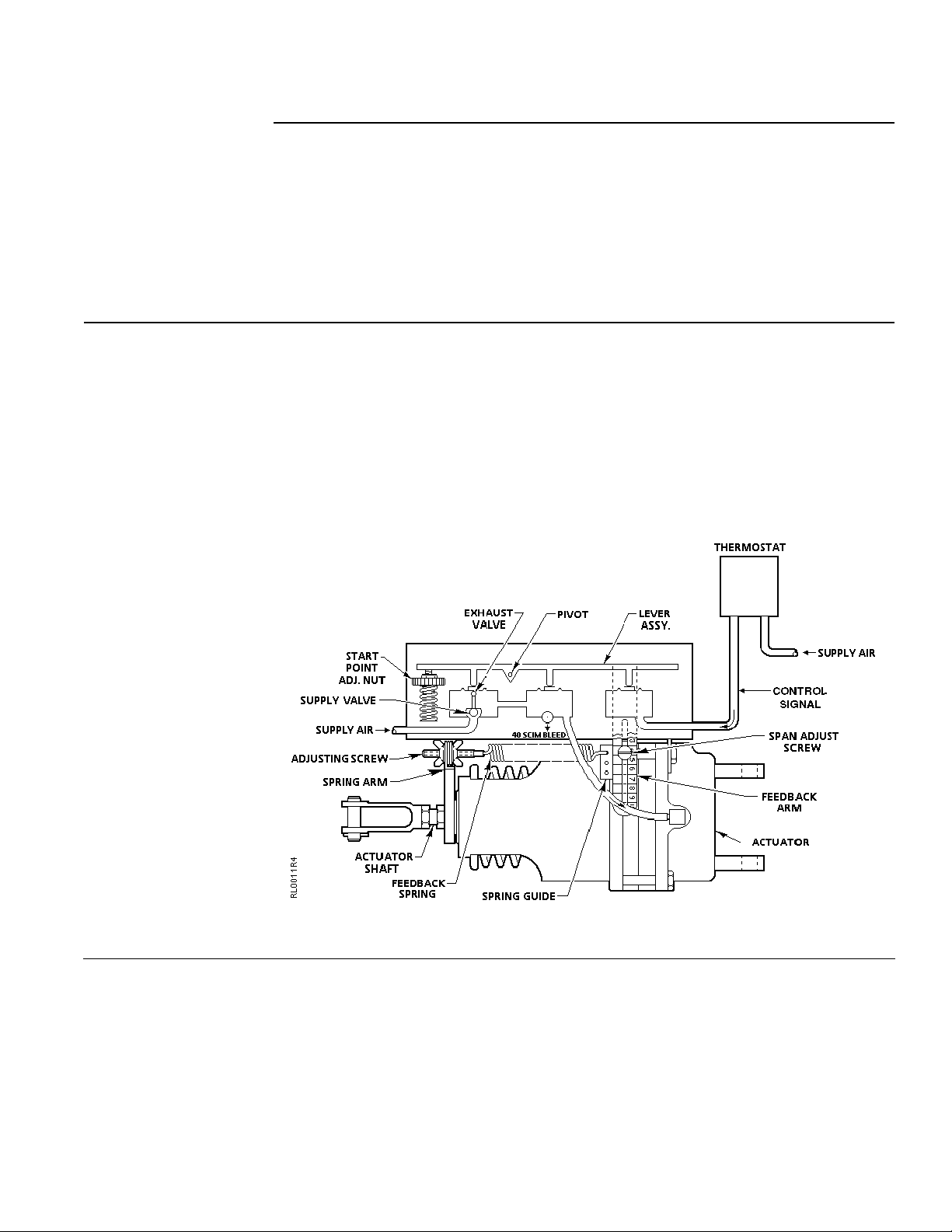
A rise in thermostat pressure will unbalance the lever assembly. See Figure 2. The shaft
movement, through the spring arm, increases tension on the feedback spring to bring
the lever assembly again into balance. A drop in thermostat pressure will unbalance the
lever assembly in the opposite direction to exhaust air from the actuator until a new
balance position is reached.
The positioning relay start point is adjustable. The start point adjustment nut shown in
Figure 2 is used to set the start point pressure. The span adjustment screw tab location
on the feedback arm and the feedback spring location on the spring guide determine the
span setting of the relay.
Figure 2. Operation Schematic.
Siemens Industry, Inc. Page 3
Page 4
Technical Instructions RL 147 Positioning Relay
Document Number 155-038P25
April 1, 2005
Positioning Relay
Components
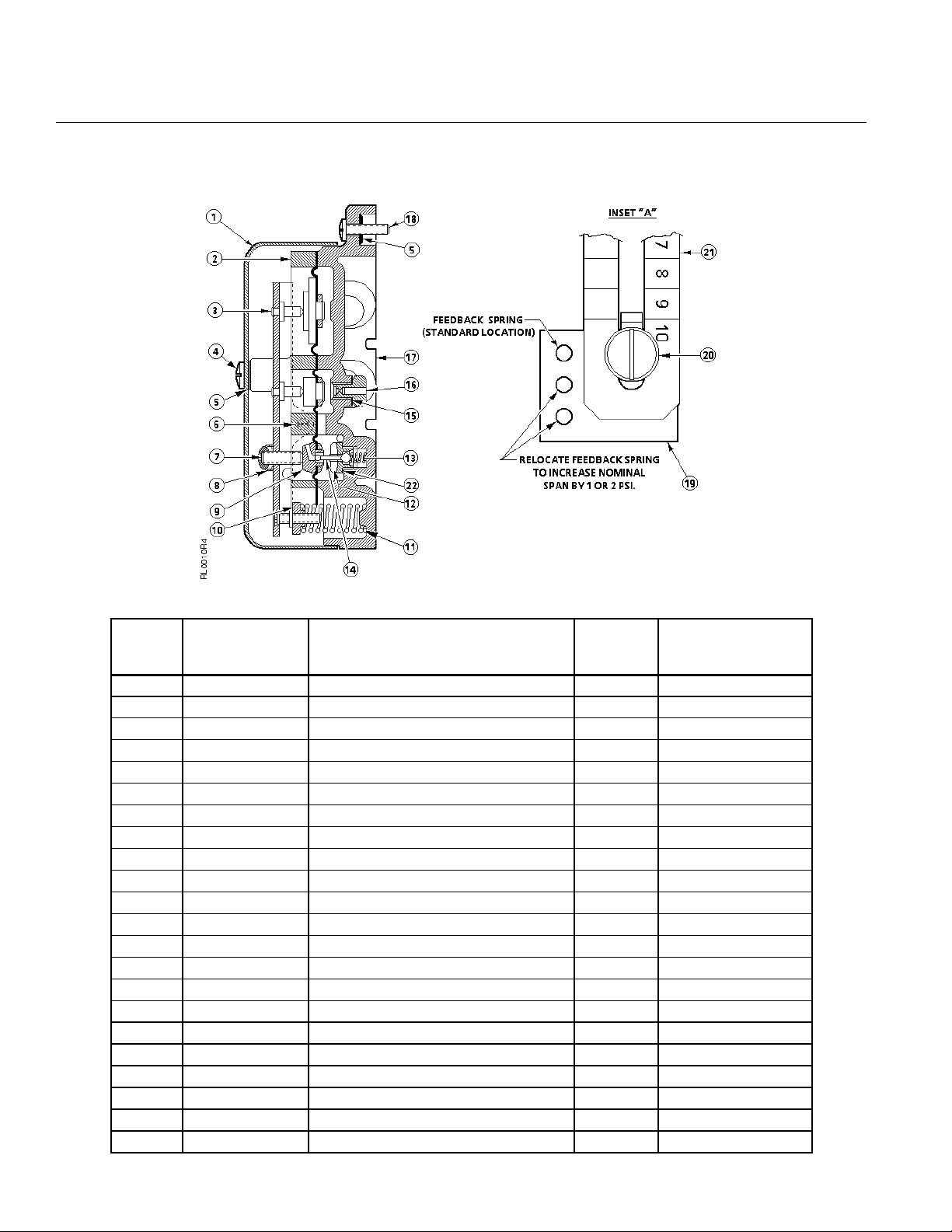
Figure 3. Construction of the RL 147 Positioning Relay.
Item Replacement
Part Number
Description Number
Material
Require
d
1 – Cover 1 Steel
2 – Plate 1 Zinc Die Casting
3 – Lever Assembly 1 –
4 – No. 8-32 Cover Screw 1 Steel
5 – Washer 1 Rubber
6 147-273 Pivot Screw 2 Stainless Steel
7 – No. 8-32 × 1/2“ Lg. Dual Pt. Set Screw 1 Steel
8 – No. 8-32 Palnut 1 Steel
9 – Diaphragm Assembly 1 –
10 – Start Point Adjustment Nut 1 Brass
11 – Start Spring 1 Music Wire
12 – Supply Valve Seat 1 Brass
13 – Supply Valve Spring 1 Phosphor Bronze
14 – Ball Assembly 1 Stainless Steel
15 – Bleed Port Gasket 1 Fiber
16 – Bleed Port 1 Brass
17 – Base 1 Zinc Die Casting
18 034-048 No. 6-32 × 5/8” Lg. Bind Hd Screw 2 Brass
19 147-297 Spring Guide 1 Steel
20 034-067K Span Adjustment Screw 1 Steel
21 – Feedback Arm 1 Steel
22 – Gasket 1 Fairprene
Page 4 Siemens Industry, Inc.
Page 5
RL 147 Positioning Relay Technical Instructions
Document Number 155-038P25
April 1, 2005
Calibration
Complete calibration instructions are included with each positioning relay.
1. Check that you have the correct feedback spring(s) attached.
2. Identify the desired operating span and the start point pressure.
NOTE: In some cases, the actuator stem travel or stroke is not identical to the
nominal value of the relay feedback spring. See Calculating the Span
Setting to determine the span setting on the feedback arm.
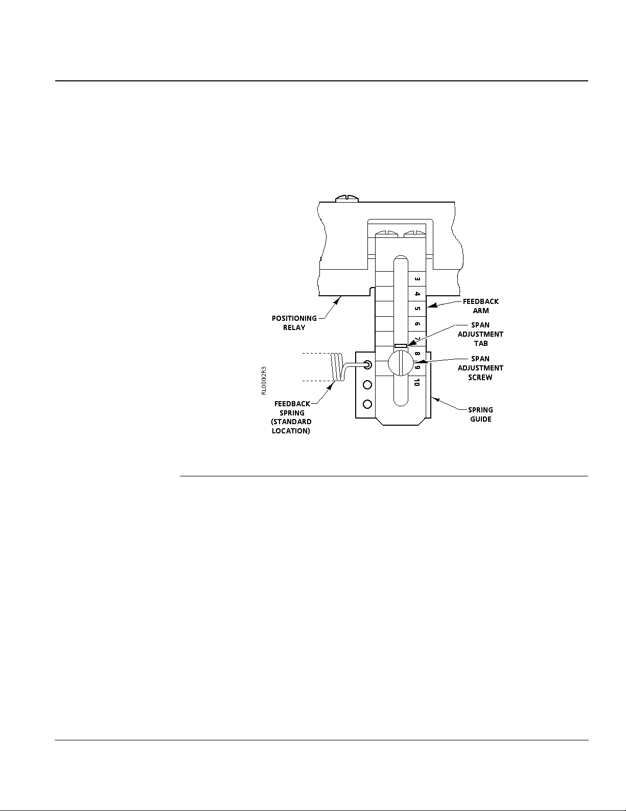
Setting the Span
Figure 4. Span Adjustment.
Shown at Span Setting 8.
See Figure 4.
The positioning relay operating span can be set for spans of 3 psig through 12 psig
(21 kPa to 83 kPa).
For spans of 3 psig through 10 psig (21 to 69 kPa):
1. Check that the feedback spring is attached to the spring guide in the hole across
from the span adjustment screw. This is identified as the standard location in
Figure 4.
2. With a screwdriver, loosen the span adjustment screw. Move the spring guide on the
feedback arm until the span adjustment tab is at the desired span setting reference
number.
NOTE: The line to the left of the number is the setting.
3. Tighten the span adjustment screw.
4. The feedback spring must be parallel to the actuator shaft or valve stem. Use openend wrenches to loosen the hex nuts holding the spring arm in position on the shaft
or stem. Align the feedback spring and tighten the hex nuts.
5. The feedback spring should have no slack or stretch in it. Adjust the wing nuts and
adjustment nut, if necessary.
Siemens Industry, Inc. Page 5
Page 6
Technical Instructions RL 147 Positioning Relay
Document Number 155-038P25
April 1, 2005
Calibration,
Continued
Adjusting the Start
Point
For spans of 11 psig or 12 psig (76 kPa or 83 kPa):
1. Move the span adjustment tab to the 10 setting on the feedback arm. Follow Steps 2
and 3 in Setting the span.
2. Move the feedback spring one hole away from the standard location for a span of
11 psig (76 kPa) and two holes away from the standard spring location for a 12 psig
(83 kPa) span. See Figure 4.
3. Follow Steps 4 and 5 in Setting the Span.
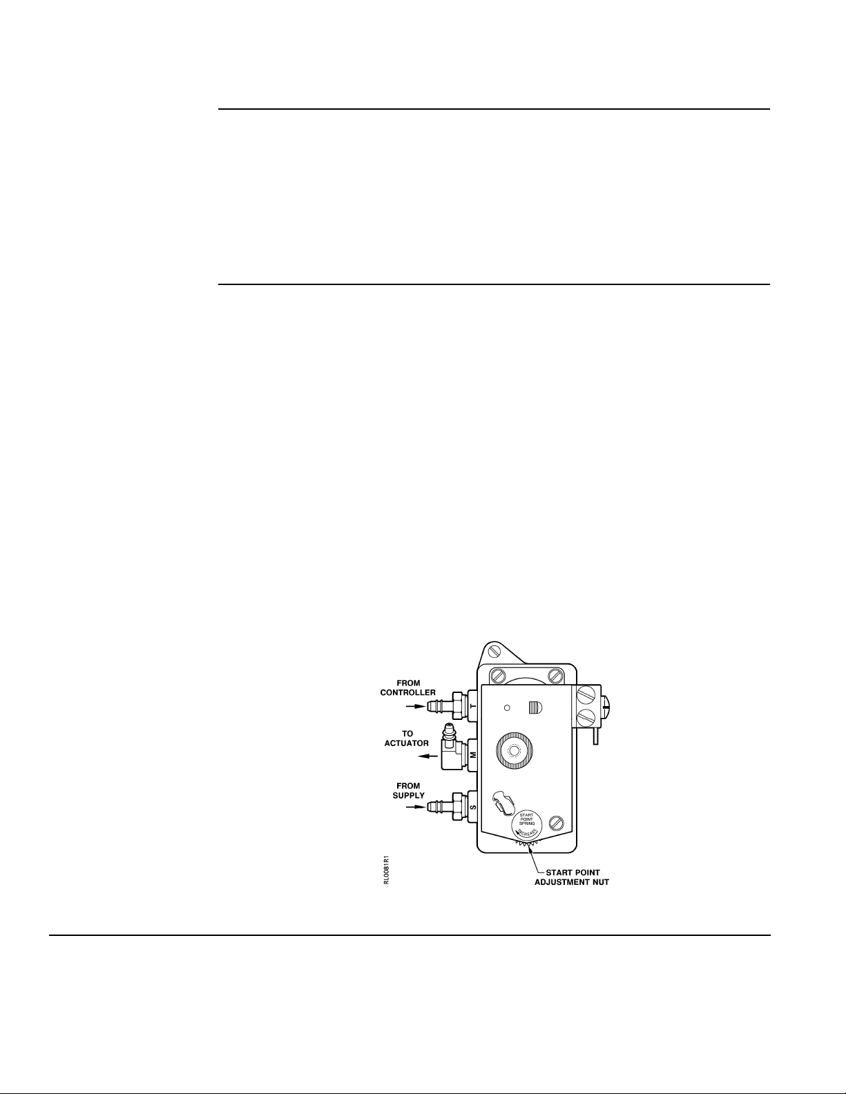
See Figure 5.
The positioning relay can be adjusted to start actuator movement at pressures between
3 psig and 10 psig (21 kPa and 69 kPa).
1. Remove the relay cover.
2. Attach tubing with a pressure gauge and squeeze bulb to the "T" Port. Supply air
should be attached to the "S" Port. The "M" Port should be attached to the connector
on the actuator.
3. Using the squeeze bulb, apply pressure to the relay. Watch the valve stem or
actuator shaft to see when it begins to move. Check the pressure gauge; this is the
start point pressure.
4. If this is not the desired start point pressure, turn the start point adjustment nut
(Figure 5) clockwise to increase the start point pressure and counterclockwise to
decrease the pressure.
5. Repeat Steps 3 and 4 until the stem or shaft begins to move at the desired pressure.
Figure 5. Start Point Adjustment.
Page 6 Siemens Industry, Inc.
Page 7

RL 147 Positioning Relay Technical Instructions
Document Number 155-038P25
April 1, 2005
Calibration,
Continued
Adjusting the Span
Calculating the Span
Setting
1. Using the squeeze bulb, apply pressure to the relay. Note the pressure at which the
stem or shaft begins to move.
2. Continue to apply pressure until the stem or shaft completes its full stroke. Note the
pressure.
3. Check the difference between the two pressures; this is the span.
4. If the span is not the desired span, move the spring guide to a higher reference
number to increase the span or lower number to decrease the span. See Figure 4.
5. Repeat Steps 1 through 4 until you get the desired span.
6. If you have moved the spring guide, adjust the spring arm so that the spring is
parallel to the stem or shaft.
7. Check the feedback spring. There should be no slack or stretch in it. Adjust the wing
nuts and adjustment nut, if necessary.
8. Fasten the relay cover. Fill in the information on the calibration label.
1. Identify the valve stem from Table 3 or 4. If the stroke of the No. 6 damper actuator
has been changed from the factory setting, see Table 7.
2. If your stem travel matches the nominal spring travel listed in Table 2, there is no
need to calculate a new span setting.
3. If your stem travel does not match the nominal spring travel listed in Table 2, choose
the spring(s) whose maximum allowable travel is equal or greater than your actual
stem travel.
4. Calculate the span setting with the following formula:
Formula for Span Setting
Span
= Desired span X Nominal spring travel
Setting
Example:
Determine the span setting for a valve having a
span of 5 psig and 5/16-inch stroke.
Select a spring with a maximum allowable range equal to or larger than the stroke.
Use the 1/4-inch spring with a 3/8-inch maximum allowable travel range.
See Table 2.
Span
Setting
Set the span adjustment tab to line 4 on the feed back arm to provide a 5 psig span
= 5 X 0.25
0.312
= 4
for this valve.
Actuator stroke
Siemens Industry, Inc. Page 7
Page 8
Technical Instructions RL 147 Positioning Relay
Document Number 155-038P25
April 1, 2005
Calibration,
Continued
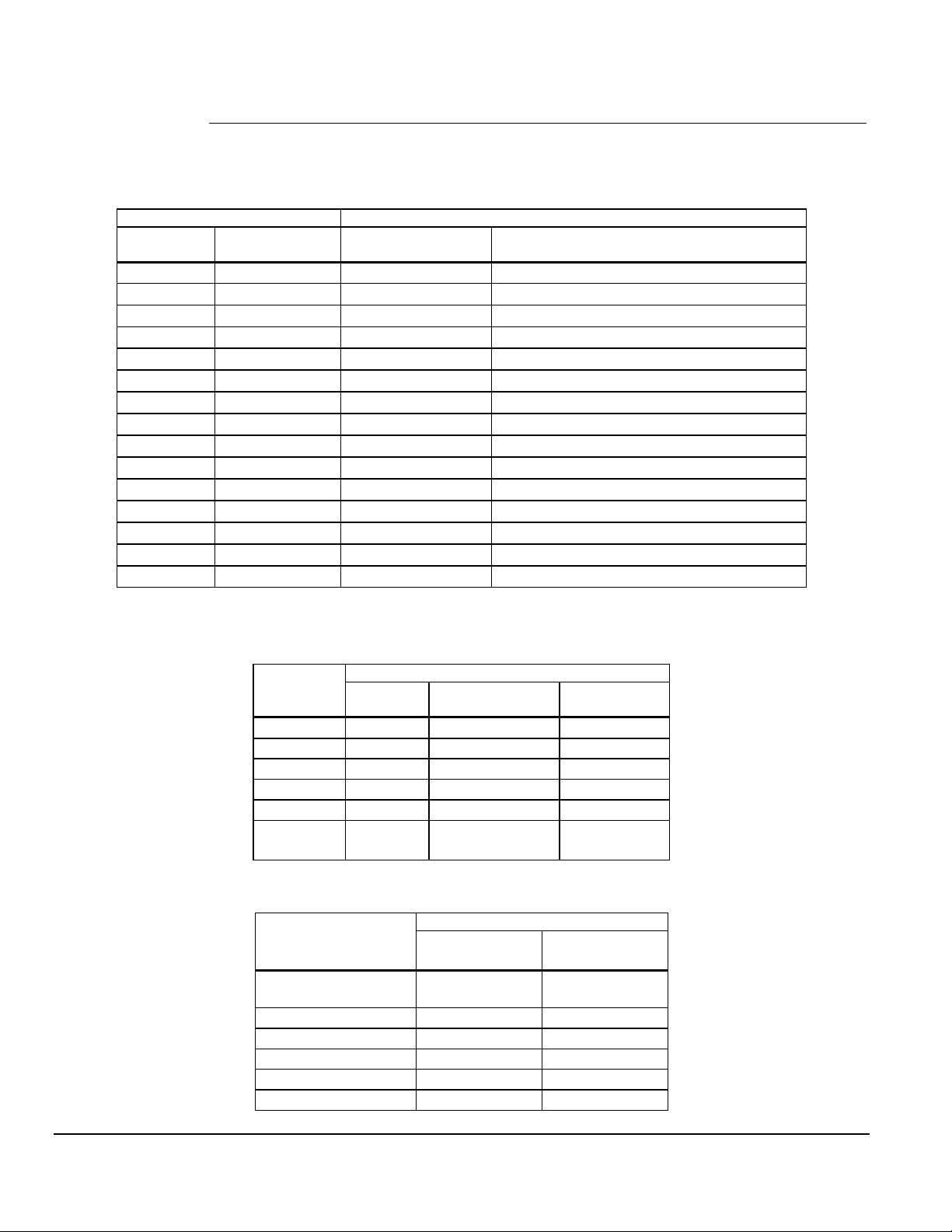
Table 2. Spring Selection.
Spring Travel Range Recommended Springs
Nominal
Inches (mm)
5/32 (5.0) 1/4 (6.4) 147-298 Small Green
1/4 (6.4) 3/8 (9.5) 147-289 Small Cadmium Plate
3/8 (9.5) 1/2 (13) (2)147-298 Small Green
3/4 (19) 1 (25) 147-290 Small Red
1 (25) 1-1/4 (32) 147-291 Long Green
1-1/4 (32) 1-5/8 (41) 147-289 plus 147-291 Small Cadmium Plate plus Long Green
1-1/2 (38) 2 (51) (2) 147-290 Small Red
1-3/4 (44) 2-1/4 (57) 147-290 plus 147-291 Small Red plus Long Green
2 (51) 2-1/2 (64) (2) 147-291 Long Green
2-3/8 (60) N/A 147-105 2" Red
3 (76) 3-1/4(83) 147-292 Long Cadmium Plate
3-3/4 (95) 4 (102) 147-301 3" Red
4 (102) 4-1/4 (108) 147-293 Blue
4 (102) 6 (152) 147-313 Zinc Pl. or Yell. Chr.
7 (178) 12-1/4 (311) 147-330 Zinc Plate
Max. Allowable
Inches (mm)
Part Number Size and Color
Table 3. Stem Travel for VP 591 Bronze Body Valves.
Stem Travel Inches (mm) Line Size
Inches
(mm)
1/2 (13) 3/8 (9.5) — 1/8 (3.2)
3/4 (19) 3/4 (19) — 3/16 (4.8)
1 (25) 3/4 (19) 3/16 (4.8) 1/4 (6.4)
1-1/4 (32) 1 (25) 1/4 (6.4) 5/16 (7.9)
1-1/2 (38) 1 (25) 1/4 (6.4) 5/16 (7.9)
2 (51) 5/8 (16) 3/8 (9.5) N.O.
Single
Seat
Double Seat WM
5/16 (7.9) N.C.
Table 4. Stem Travel for VF 599 Valve Bodies.
Stem Travel in Inches (mm) Line size
in Inches
(mm)
1/2 through 2
(15 though 50)
2-1/2 (65) 3/4 (20) 3/4 (20)
3 (80) 3/4 (20) 3/4 (20)
4 (100) — 1-1/2 (40)
5 (125) — 1-1/2 (40)
6 (150) — 1-1/2 (40)
8-inch
Actuator
3/4 (20) —
5/16 (7.9)
12-inch
Actuator
Page 8 Siemens Industry, Inc.
Page 9

RL 147 Positioning Relay Technical Instructions
Document Number 155-038P25
April 1, 2005
Calibration,
Continued
Table 5. Stem Travel Listed by 591 or 593 Flowrite Valve Product Number.
Flowrite
Product
Number
Stem
Travel
Inches
(mm)
591-6480 5/8 (16)
591-6490 3/4 (19)
591-6540 5/8 (16)
591-6600 1/8 (3.2)
591-6610 3/16 (4.8)
591-6620 1/4 (6.4)
591-6630 5/16 (7.9)
591-6640 5/16 (7.9)
591-6650 5/16 (7.9)
591-6720 5/8 (16)
591-6730 3/4 (19)
591-6740 1 (25)
591-6840 3/8 (9.5)
591-6850 9/16 (14)
591-6860 9/16 (14)
591-6870 5/16 (7.9)
591-6880 9/16 (14)
591-6890 9/16 (14)
591-6900 1/4 (6.4)
591-6910 1/4 (6.4)
591-6920 5/16 (7.9)
591-6930 9/16 (14)
591-6940 3/16 (4.8)
591-6950 1/4 (6.4)
591-6960 1/4 (6.4)
591-6970 3/8 (9.5)
591-6980 3/16 (4.8)
591-6990 1/4 (6.4)
591-7000 1/4 (6.4)
591-7010 5/16 (7.9)
591-7020 3/16 (4.8)
591-7030 1/4 (6.4)
591-7040 1/4 (6.4)
591-7050 3/8 (9.5)
591-7060 3/8 (9.5)
591-7070 9/16 (14)
591-7080 9/16 (14)
591-7090 3/16 (4.8)
591-7100 5/16 (7.9)
591-7110 9/16 (14)
591-7870 3/4 (19)
591-7871 3/4 (19)
Flowrite
Product
Number
Stem
Travel
Inches
(mm)
591-7872 1 (25)
591-7873 1 (25)
591-7874 1 (25)
591-7875 3/4 (19)
591-7876 3/4 (19)
591-7877 1 (25)
591-7878 1 (25)
591-7879 1 (25)
591-7971 3/8 (9.5)
591-7972 3/4 (19)
591-7973 3/4 (19)
591-7974 1 (25)
591-7975 1 (25)
591-7976 1 (25)
591-7977 3/8 (9.5)
591-7978 3/4 (19)
591-7979 3/4 (19)
591-7980 1 (25)
591-7981 1 (25)
591-7982 1 (25)
591-8016 5/8 (16)
591-8017 5/8 (16)
591-8018 3/4 (19)
591-8019 3/4 (19)
591-8020 1 (25)
591-8021 1 (25)
591-8028 5/8 (16)
591-8029 3/4 (19)
591-8030 1 (25)
591-8071 3/8 (9.5)
591-8072 3/4 (19)
591-8073 3/4 (19)
591-8074 1 (25)
591-8075 1 (25)
591-8076 1 (25)
591-8077 3/8 (9.5)
591-8078 3/4 (19)
591-8079 3/4 (19)
591-8080 1 (25)
591-8081 1 (25)
591-8082 1 (25)
591-8330 5/8 (16)
Flowrite
Product
Number
Stem
Travel
Inches
(mm)
591-8331 5/8 (16)
591-8332 3/4 (19)
591-8336 5/8 (16)
591-8337 5/8 (16)
591-8338 3/4 (19)
591-8339 3/4 (19)
591-8340 1 (25)
591-8341 1 (25)
591-8342 1-1/2 (38)
591-8344 1-1/2 (38)
591-8350 1-1/2 (38)
591-8351 1-1/8 (29)
591-8352 1-1/8 (29)
591-8353 1-1/8 (29)
591-8354 1-1/8 (29)
591-8355 1-1/8 (29)
591-8356 1-1/8 (29)
591-8357 1-1/8 (29)
591-8358 1-1/4 (32)
591-8359 1-1/8 (29)
591-8360 1-1/2 (38)
591-8362 1-1/2 (38)
591-8364 1-1/8 (29)
591-8365 1-1/8 (29)
591-8366 1-1/8 (29)
591-8367 1-1/8 (29)
591-8368 1-1/8 (29)
591-8369 1-1/8 (29)
591-8370 1-1/8 (29)
591-8371 1-1/8 (29)
591-8372 1-1/4 (32)
591-8373 1-1/4 (32)
591-8374 1-1/2 (38)
591-8376 1-1/2 (38)
591-8378 1-1/4 (32)
591-8379 1-1/4 (32)
591-8380 1-1/4 (32)
593-8381 1-1/4 (32)
593-8382 1-1/2 (38)
593-8383 1-1/2 (38)
593-8388 3/4 (19)
593-8389 3/4 (19)
Flowrite
Product
Number
Stem
Travel
Inches
(mm)
593-8390 3/4 (19)
593-8391 3/4 (19)
593-8392 1-1/8 (29)
593-8393 1-1/8 (29)
593-8394 1-1/4 (32)
593-8395 1-1/4 (32)
593-8396 1-1/4 (32)
593-8397 1-1/4 (32)
593-8398 1-1/4 (32)
593-8399 1-1/4 (32)
593-8400 1-1/4 (32)
593-8401 1-1/4 (32)
593-8402 1-1/2 (38)
593-8403 1-1/2 (38)
593-8404 1-1/4 (32)
593-8405 1-1/4 (32)
593-8406 1-1/4 (32)
593-8407 1-1/4 (32)
593-8410 1-1/2 (38)
593-8411 1-1/2 (38)
593-8412 1-3/8 (35)
593-8413 1-3/8 (35)
593-8415 1 (25)
593-8416 1 (25)
593-8419 1 (25)
593-8420 1 (25)
593-8421 1-3/8 (35)
593-8422 1-3/8 (35)
593-8423 1-3/8 (35)
594-8343* 1-1/2 (38)
594-8345* 1-1/2 (38)
594-8361* 1-1/2 (38)
594-8363* 1-1/2 (38)
594-8375* 1-1/2 (38)
594-8377* 1-1/2 (38)
* RL 147 is standard with
the product.
Siemens Industry, Inc. Page 9
Page 10
Technical Instructions RL 147 Positioning Relay
Document Number 155-038P25
April 1, 2005
Calibration,
Continued
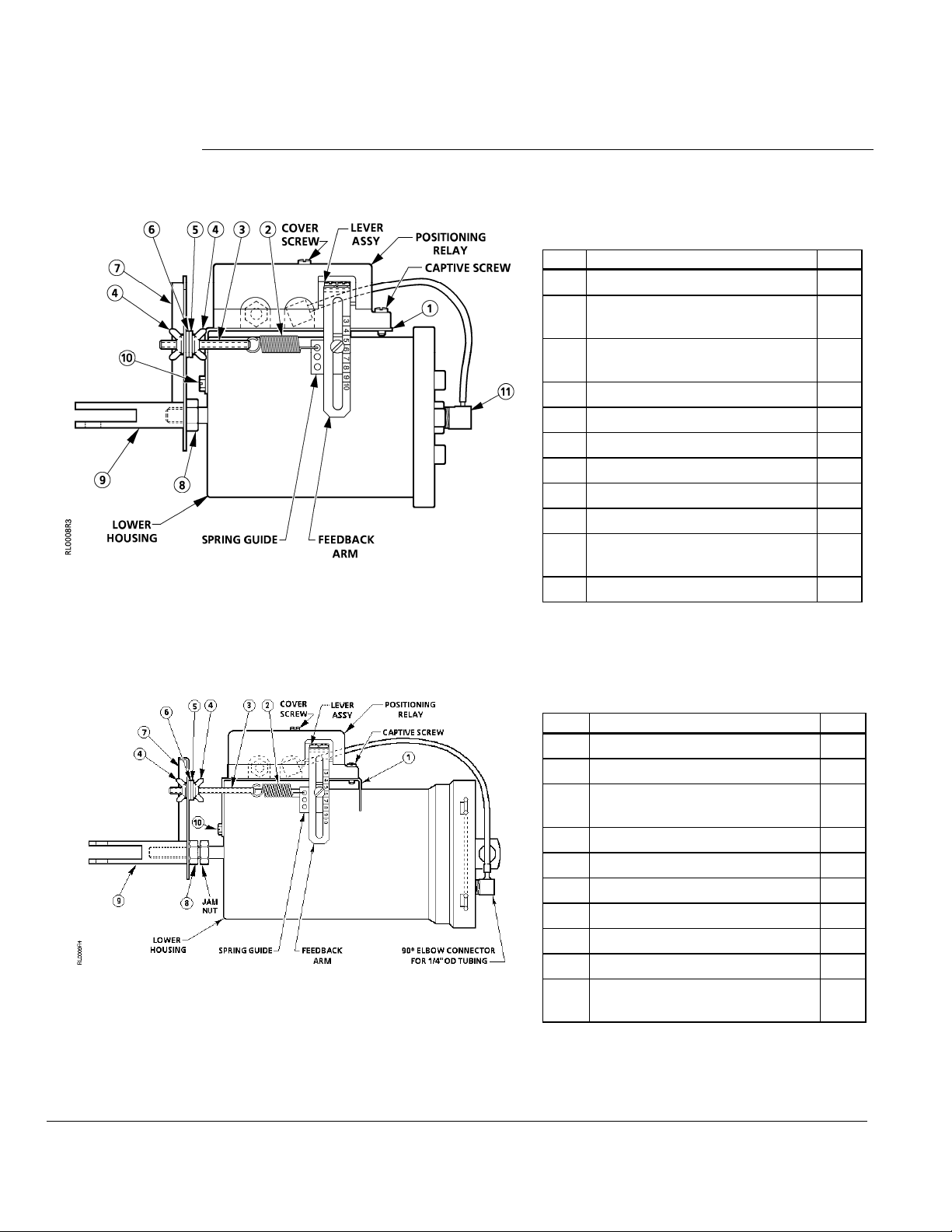
Figure 6. Positioning Relay Mounted on the
Figure 7. Positioning Relay Mounted on the
No. 3 Damper Actuator.
No. 4 Damper Actuator.
Table 6. Mounting Kit 147-104 for the
No. 3 Damper Actuator.
Item Description Qty.
1 Mounting Bracket 1
2 Feedback Spring
(for 2-3/8" stroke)
3 Adjusting Screw 1-3/4" (44 mm)
long
4 Wing Nut 2
5 Lock Washer 1
6 Flat Washer 1
7 Spring Arm 1
8 3/8-24 Hex Nut 1
9 Clevis 1
10 No. 10-16 1/2" (13 mm) Slotted
Hex Screw
11 90° Elbow Connector 1
Table 7. Mounting Kit 147-314 for the
No. 4 Damper Actuator
Item Description Qty.
1 Mounting Bracket 1
2 Feedback Spring 1
3 Adjusting Screw 1-3/4" (44 mm)
long
4 Wing Nut 2
5 Lock Washer 1
6 Flat Washer 1
7 Spring Arm 1
8 3/8-24 Hex Nut 2
9 Clevis 1
10 No. 10-16 1/2" (13 mm) Slotted
Hex Screw
1
1
2
1
1
Page 10 Siemens Industry, Inc.
Page 11
RL 147 Positioning Relay Technical Instructions
Document Number 155-038P25
April 1, 2005
Calibration,
Continued
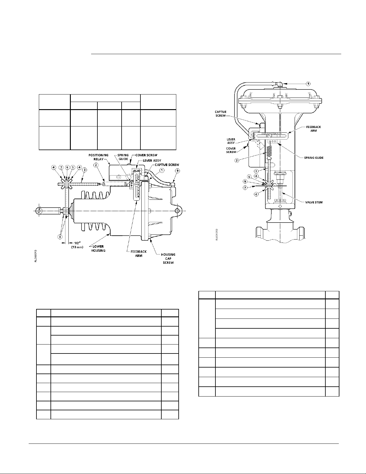
Table 8. Spring Selection for Adjustable Stroke of
the No. 6 Damper Actuator.
Actuator
Stroke
3-1/4 to 4
(82 to 102)
2-29/32 to
3-1/4
(74 to 82)
Feedback Spring
Color Nominal Max
Blue 4 (102) 4-1/4
(108)
Cadmium 3 (76) 3-1/4
(82)
Adjusting
Screw
4-1/2 (114)
long
1-3/4 (44)
long
Figure 9. Positioning Relay Mounted on a
VP 591 8-inch Valve Actuator.
Valve Actuator.
Figure 8. Positioning Relay Mounted on the No. 6
Damper Actuator.
Table 9. Mounting Kit 147-276 for the No. 6 Damper
Actuator.
Item Description Qty.
1
Mounting Bracket 1
2
Feedback Spring 4" (102 mm) stroke (blue) 1
Feedback Spring 3" (76 mm) stroke (Cad.) 1
3
Adjusting Screw 4-1/2" (114 mm) long 1
Adjusting Screw 1-3/4" (44 mm) long 1
4
Wing Nut 2
5
Lock Washer 1
6
Flat Washer 1
7
Spring Arm 1
8
3/8-24 Hex Nut 2
9
90° Elbow Connector 1
Table 10. Mounting Kit 147-333 for the VP 591 8-inch
Item Description Qty.
2 Feedback Spring-Small Cadmium Plate 2
Feedback Spring-Small Red 1
Feedback Spring-Large Green 1
Feedback Spring-Small Green 2
3 Adjusting Screw 4-inch (102 mm) long 1
4 Wing Nut 2
5 Lock Washer 1
6 Flat Washer 1
7 Spring Arm 2
9 90° Elbow Connector 1
Siemens Industry, Inc. Page 11
Page 12
Technical Instructions RL 147 Positioning Relay
Document Number 155-038P25
April 1, 2005
Calibration,
Continued
1
LEVER
ASSEMBLY
POSITIONING
RELAY
2
3
4
7
4
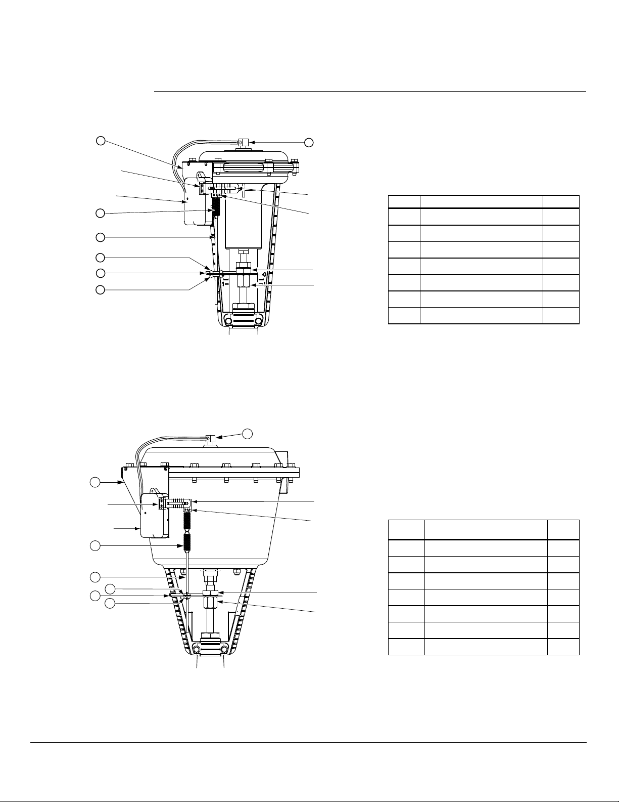
Figure 10. Positioning Relay Mounted on a
Flowrite 599 Series 8-inch Valve Actuator.
9
Table 11. Kit 599-00426 for the
Flowrite Series 599 8-inch
FEEDBACK
ARM
SPRING
GUIDE
Item Description Qty.
RL 147 Positioning Relay 1
Valve Actuator.
1 Mounting Bracket 1
2 Feedback Spring 1
JAM
NUT
STEM
NUT
3 Adjusting Screw 1
4 Wing Nut 2
7 Spring Arm 1
9 90° Elbow Connector 1
RL0088.R1
9
1
LEVER
ASSEMBLY
POSITIONING
RELAY
2
3
4
7
4
RL0091.R1
Figure 11. Positioning Relay Mounted on a
Flowrite Series 599 12-inch Valve Actuator.
FEEDBACK
ARM
SPRING
GUIDE
JAM
NUT
STEM
NUT
Table 12. Kit 599-00423 for the
Flowrite Series 599 12-inch
Valve Actuator.
Item Description Qty.
RL 147 Positioning Relay 1
1 Mounting Bracket 1
2 Feedback Spring 2
3 Adjusting Screw 1
4 Wing Nut 2
7 Spring Arm 1
9 90° Elbow Connector 1
Page 12 Siemens Industry, Inc.
Page 13
RL 147 Positioning Relay Technical Instructions
Document Number 155-038P25
April 1, 2005
Calibration,
Continued
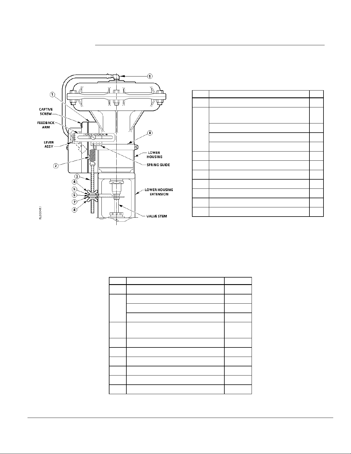
Table 13. Mounting Kit 147-277*
for Flowrite 8-inch Valve Actuator
Models 1 and 2.
Item Description Qty.
1 Mounting Bracket 1
Feedback Spring, Small Cadmium
Plate
2 Feedback Spring, Small Red 1
Feedback Spring, Large Green 1
Feedback Spring, Small Green 2
3 Adjusting Screw, 4-1/2" (114 mm) 1
4 Wing Nut 2
5 Lock Washer 1
6 Flat Washer 1
7 Spring Arm 1
8 Sure-tite Clamp 1
9 90° Elbow Connector 1
2
Figure 12. Positioning Relay Mounted on the
Flowrite 8-inch Actuator (Models 1 and 2)
and Super Flowrite.
Table 14. Mounting Kit 147-279 for Super Flowrite and
12-inch Flowrite Before March 1978. See Figure 12.
Item Description Quantity
1 Mounting Bracket 1
Feedback Spring-Small Cad. Plate 2
2 Feedback Spring-Small Red 2
Feedback Spring-Large Green 1
3 Adjusting Screw-4-1/2" (114 mm)
long
4 Wing Nut 2
5 Lock Washer 1
6 Flat Washer 1
7 Spring Arm 1
8 Sure-Tite Clamp 1
9 90° Elbow Connector 1
*Also order spring arm No. 147-307 for use with
VF 591 5-inch and 6-inch balanced valves.
1
Siemens Industry, Inc. Page 13
Page 14
Technical Instructions RL 147 Positioning Relay
Document Number 155-038P25
April 1, 2005
Calibration,
Continued
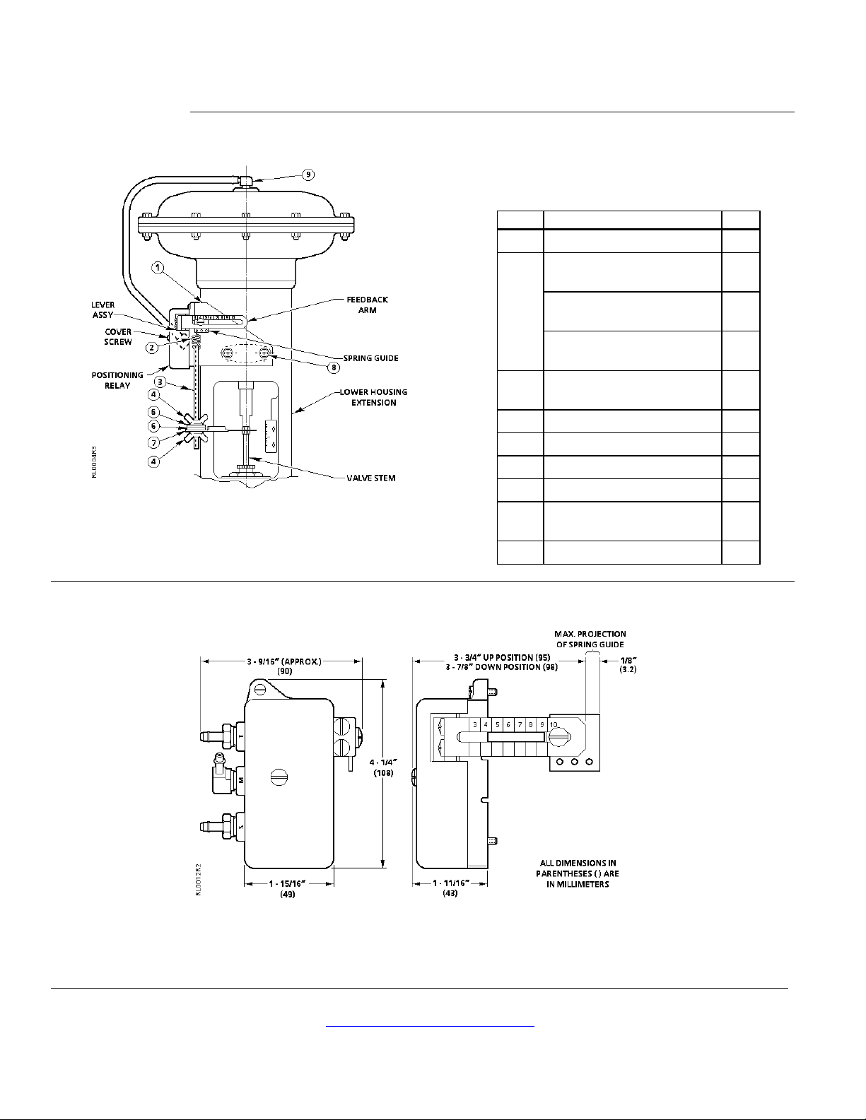
Figure 13. Positioning Relay Mounted on a
Dimensions
VP 591/3 Flowrite Valve Actuator.
Table 15. Mounting Kit 147-311 for the
VP 591/3 Flowrite Valve Actuator.
Item Description Qty.
1 Mounting Bracket 1
Feedback Spring, Small
2
Cadmium Plate
2 Feedback Spring, Small
2
Red
Feedback Spring, Large
2
Green
3 Adjusting Screw, 6-1/2"
1
(165 mm)
4 Wing Nut 2
5 Lock Washer 1
6 Flat Washer 1
7 Spring Arm 1
8 5/16-18 × 1/2 long Cap
2
Screw
9 90° Elbow Connector 1
Figure 14. Dimensions in Inches (Millimeters).
Information in this publication is based on current specifications. The company reserves the right to make changes in specifications and models as
design improvements are introduced. Powers is a registered trademark of Siemens Industry, Inc. Product or company names mentioned herein
may be the trademarks of their respective owners. © 2005 Siemens Industry, Inc.
Siemens Industry, Inc.
Building Technologies Division
1000 Deerfield Parkway
Buffalo Grove, IL 60089
+ 1 847-215-1000
Your feedback is important to us. If you have
comments about this document, please send them
to [email protected]
Document No. 155-038P25
Printed in the USA
Page 14
 Loading...