

Page 1
Powers™ Controls
Technical Instructions
CP 567 Control Cabinets
9-inch depth (for pneumatic installations).
Size
Installation
1
Pneumatic
567-351
19-1/2 (495) × 16-3/8 (416) × 5-3/4 (146)
2
Electronic
567-454
20 (508) × 20 (508) × 6 (152)
3
Pneumatic
567-352
24-5/16 (617) × 24-3/8 (619) × 9-3/8 (238)
3
Electronic
567-452
24-5/16 (617) × 24-3/8 (619) × 6 (152)
4
Pneumatic
567-353
36-1/2 (927) × 24-3/8 (619) × 9-3/8 (238)
4
Electronic
567-453
36-1/2 (927) × 24-3/8 (619) × 6 (152)
1
Pneumatic
567-361
3
Either
567-362
4
Either
567-363
3
Either
567-372
4
Either
567-373
Flush Mount Cabinet
1
Pneumatic
567-391
See Figure 7
Flush Mount Door Kit
1
Pneumatic
567-390
See Figure 8
Document No. 155-272P25
CP 567-7
November 12, 2007
Description
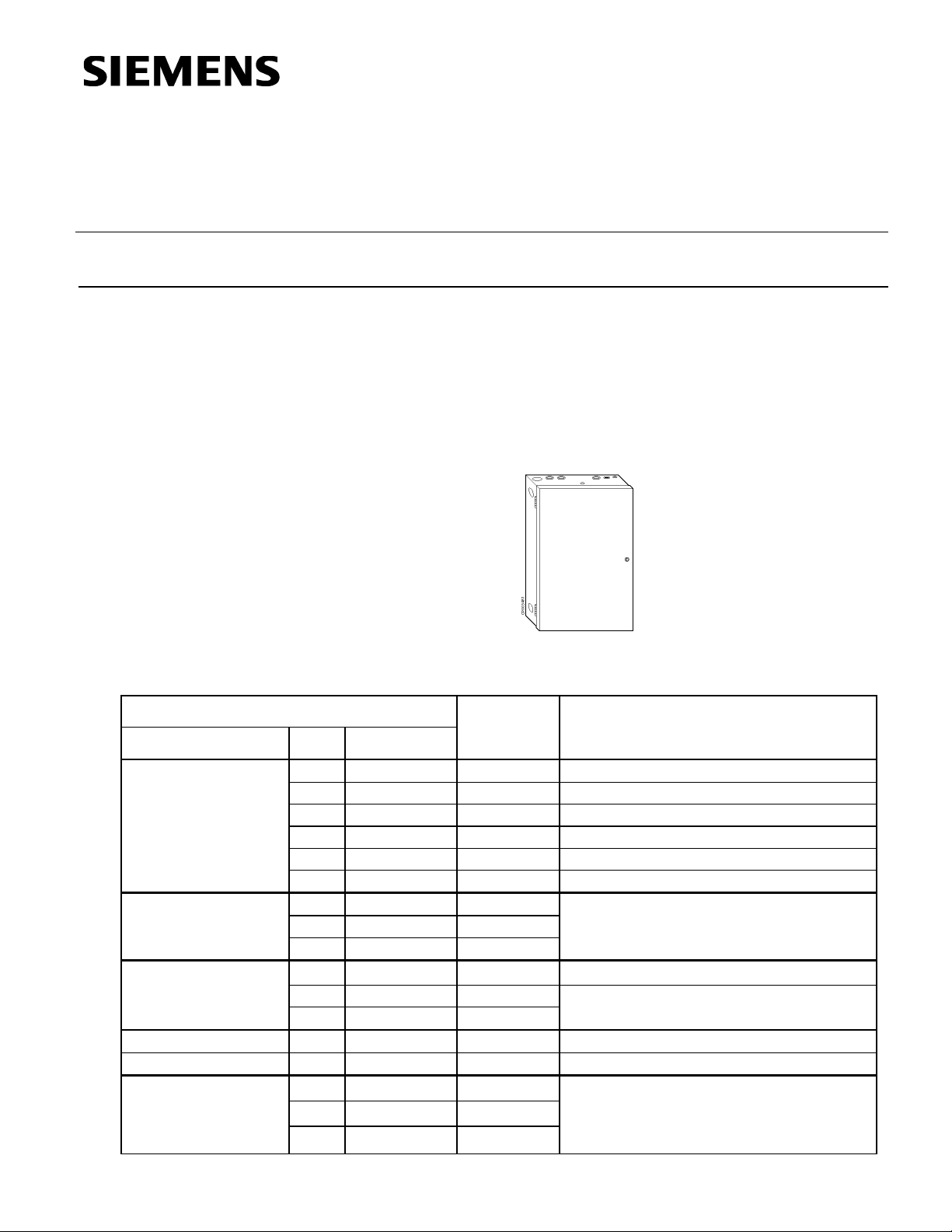
CP 567 Control Cabinets are designed to conveniently group control system
components (Figure 1). Control components can be mounted on the door or mounted
within the cabinet enclosure using the perforated mounting plate. Cabinets are available
in four Sizes: 1, 2, 3 and 4. See Table 1 for product numbers and dimensions.
• The cabinet enclosure, door, and perforated mounting plate for Sizes 1, 3 and 4 may
be ordered separately.
• The Size 1 cabinet enclosure is available in a flush mount version.
• Size 3 and 4 cabinets are available in 6-inch depth (for electronic installations) or
Figure 1. CP 567 Control Cabinet.
Table 1. Product Numbers.
Description Product
Numbers
Dimensions
Inches (mm)
H × W × D
Cabinet Assembly
Cabinet Door
Cabinet Enclosure 1 Pneumatic 567-371 See Figures 4 and 5
Perforated Mounting
Plate
Siemens Industry, Inc.
1 Pneumatic 567-381 –
3 Either 567-382
4 Either 567-383
See Figure 4
See Figures 4 and 5
Page 2

Technical Instructions CP 567 Control Cabinets
Document Number 155-272P25
November 12, 2007
Application
Features
CP 567 Control Cabinets provide a convenient central location for equipment mounting,
termination of piping, adjustment, and calibration.
The door and mounting plate can be separated from the cabinet enclosure. The empty
cabinet enclosure can be installed at the job to permit early rough-in of conduit.
Controls may be mounted to the door and mounting plate either at the job site or at the
office and attached to the cabinet enclosure at your convenience. After reassembly, final
connections are made.
Cabinets may be used with pneumatic systems employing either copper or polyethylene
tubing for transmission lines, with wired electric/electronic systems, or with a
combination of both.
Pneumatic tubing within the cabinet enclosure should be polyethylene for a flexible
connection to hinged door components and for easy installation and arrangement.
• Cabinets are symmetrical; therefore, they can be mounted with the door hinge on
the left or right hand side.
• Door is removable.
• Attractive gray finish permits use in occupied areas.
• Removable perforated mounting plate permits mounting controls inside the cabinet
without drilling holes.
• All cabinets can be wall or floor mounted.
Specifications
• Support kits are available for floor mounting (medium and large cabinets only).
• Knockouts are provided for electrical or pneumatic piping.
• Cabinets are listed under UL 508 Industrial Control Panel Enclosures.
• CSA approved file LR84214.
• NEMA TYPE 1 style of enclosure.
• Height and width dimensions and cabinet color are the same for automation and
pneumatic cabinets for a uniform look and mounting.
Cabinet Sizes See Table 1
Dimensions:
Cabinet, Door, Subpanel See Figures 4 through 8 and
Tables 6 and 7
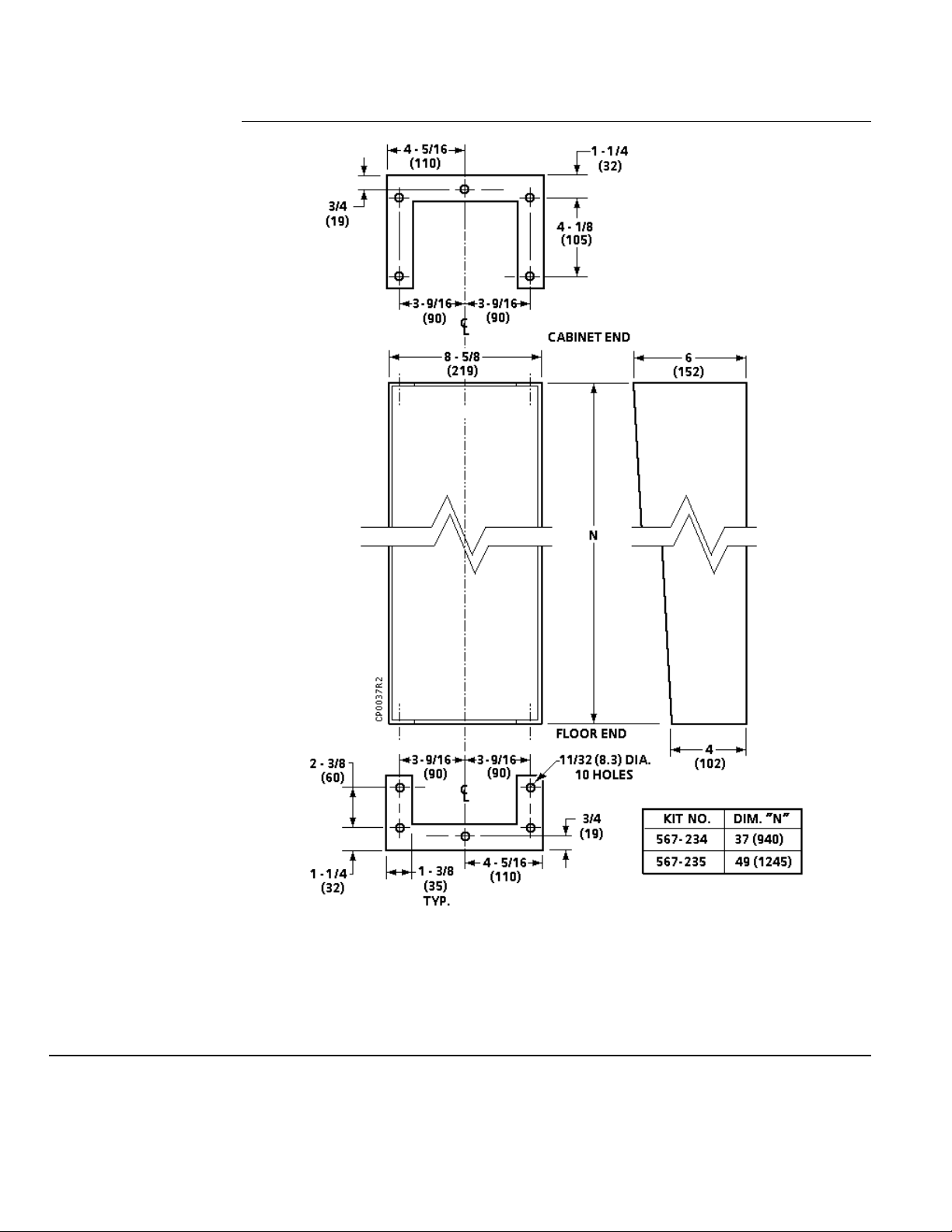
Supports See Figure 6
Mounting:
Wall See Figure 4 and Table 6
Floor See Figure 5
Flush (in wall) See Figures 7 and 8 and Table 7
Page 2 Siemens Industry, Inc.
Page 3
CP 567 Control Cabinets Technical Instructions
Knockouts-Electrical Conduit Size:
Support Size
Height
Weight
Document Number 155-272P25
November 12, 2007
Specifications,
Continued
Accessories
Size 1 and Flush Mount Cabinets
Top (3) 1-1/4 or 1-1/2, (1) 3/4 or 1,
(2) 1/2 or 3/4, (1) 7/16
Bottom (3) 1-1/4 or 1-1/2, (1) 3/4 or 1,
(2) 1/2 or 3/4, (1) 7/16
Right Side (2) 2
Left Side (2) 2
Size 2, Size 3 and Size 4 Cabinets
Top (1) 2, (3) 1-1/4 or 1-1/2,
(1) 3/4 or 1, (1) 1/2 or 3/4, (1) 7/16
Bottom (1) 2, (3) 1-1/4 or 1-1/2,
(1) 3/4 or 1, (1) 1/2 or 3/4, (1) 7/16
Right Side (2) 2
Left Side (2) 2
Material (Steel):
Cabinet (Size 1, 2, 3 and Flush Mount) 16 gauge 0.0598 (1.5 mm)
Door (Size 1, 2, 3 and Flush Mount) 16 gauge 0.0598 (1.5 mm)
Cabinet (Size 4) 14 gauge 0.0747 (1.9 mm)
Door (Size 4) 14 gauge 0.0747 (1.9 mm)
Mounting Plate 16 gauge 0.0598 (1.5 mm)
Supports 14 gauge 0.0747 (1.9 mm)
Finish Gray
Weight:
Size 1 Cabinet Assembly 20 lb (9 kg)
Size 2 Cabinet Assembly 28 lb (13 kg)
Size 3 Cabinet Assembly 39 lb (18 kg)
Size 4 Cabinet Assembly 72 lb (33 kg)
Flush Mount Enclosure 20 lb (9 kg)
Flush Mount Kit 8 lb (3.6 kg)
Support Legs See Table 2
Replacement Door Lock and Key Assembly 567-225
Floor Mount Support Kit See Table 2
(2 supports, hardware)
Touch-up Spray Paint, 16 oz Can
Gray 544-459
Blue 534-500
Cabinet Light See I.D. Number 3296
in the Field Purchasing Guide
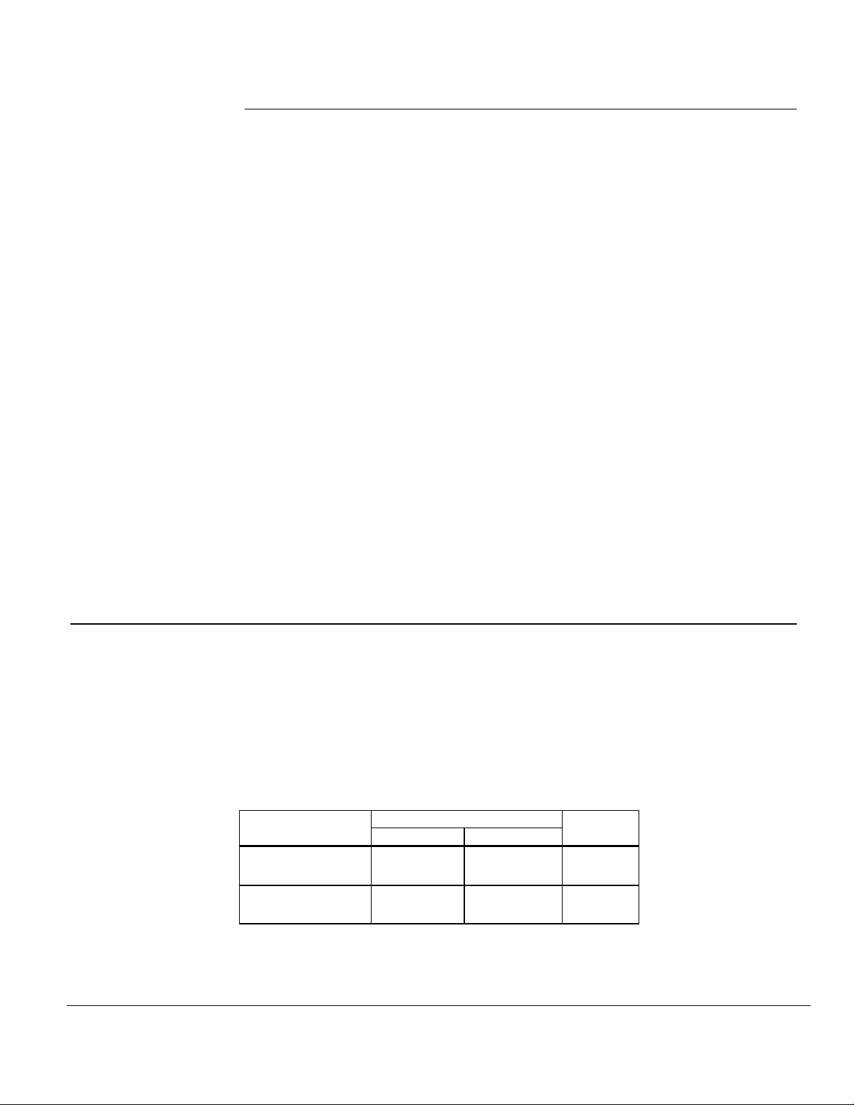
Table 2. Floor Mount Support Kit.
Cabinet Size to be
Supported
Size 3 49 inches
40 lb (18 kg) 567-335
Order
Number
(1245 mm)
Size 4 37 inches
30 lb (14 kg) 567-334
(940 mm)
NOTE: The six-inch deep cabinets do not have floor mount support kits.
Siemens Industry, Inc. Page 3
Page 4
Technical Instructions CP 567 Control Cabinets
lb (Kg)
Switches That Can Be Mounted
on Door
Document Number 155-272P25
November 12, 2007
Door Layout
NOTE: Controls cannot be mounted to the door of the flush mount cabinet.
Perform the following steps when preparing to lay out a cabinet door:
1. Determine controls to be mounted on the door.
2. Determine if the controls mounted in the door will clear the mounting plate when
tubing or wires are attached. See Figure 3 and Table 5 for dimensions. Table 4
provides the approximate space requirements for controls frequently mounted in the
door.
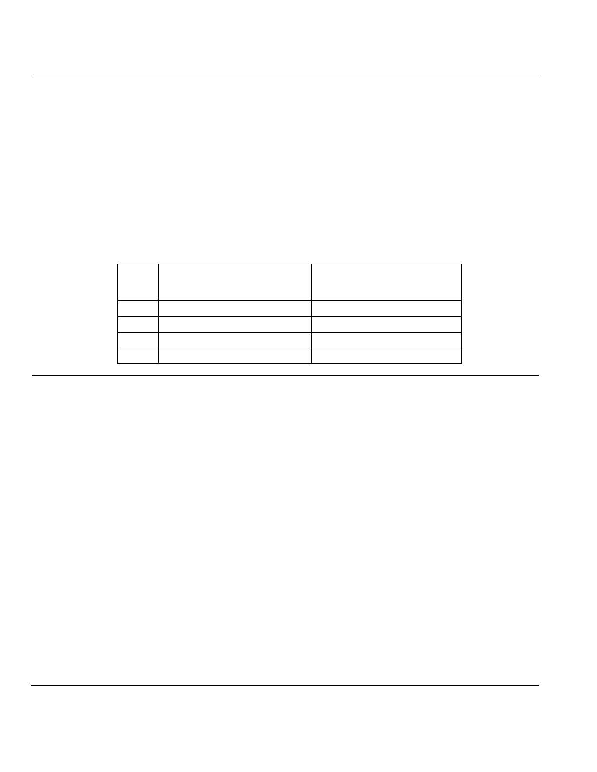
3. Determine if the total weight of the controls, (see Table 4) to be mounted on the
door are within the maximum weight limitations shown in Table 3. If weight
limitations are exceeded, the door might sag and prevent proper closure.
Table 3. Weight Limitations.
Cabinet
Size
Size 1 21 (9.5) 14
Size 2 24 (11) 16
Size 3 30 (14) 20
Size 4 93 (42) 62
Maximum Weight of Controls
That Can Be Mounted on Door
Maximum Number of Selector
Cabinet Installation
(Non-flush mount)
1. There are four keyhole mounting holes in the back surface of the cabinet. Their
sizes and locations are shown in Figure 5. Use wall anchors that are suitable to
support the weight of the cabinet and its contents.
2. If more than one cabinet is to be mounted in the same location, allow at least
2 inches (51 mm) between cabinets to provide space for doors to open properly.
3. The cabinets are symmetrical before cutouts have been made, so the door can be
mounted with the hinge on the left or right side.
4. Determine the size of the knockouts required for the number and size of pneumatic
tubes and wires to be brought into the cabinet.
5. If more than one knockout is required, divide the tubes and wires for easy
connection to the controls.
6. If a cabinet light is required, order per instructions under accessories. The
recommended mini work light has a 2-inch diameter by 4-inchlong (51 mm ×
102 mm) bulb holder on a 15-inch (381 mm) long flexible metal arm.
a. Remove the plug and mounting bracket from the light.
b. Punch out the 7/16-inch (11 mm) diameter knockout in the center of the top of
the cabinet.
c. Attach the light using the nut and washer provided with it.
Page 4 Siemens Industry, Inc.
d. Wire the light cord in compliance with local electrical codes.
Page 5
CP 567 Control Cabinets Technical Instructions
Document Number 155-272P25
November 12, 2007
Controls Installation
NOTE: It might be easier to remove the door from the cabinet and then mount the
controls onto the door or the mounting plate.
1. The space required for the controls mounted in the door or the mounting plate is
shown in Table 4. Space available between the door and the mounting plate is
shown in Figure 4, Table 5, and Table 6.
2. Arrange the controls on the mounting plate to avoid interference with the controls on
the door. Arrange the controls in logical groupings for easy access to fitting and
wiring terminals. Table 4 shows the approximate space required for controls
frequently mounted on the mounting plate in the cabinet.
3. In some cases it might be easier to remove the mounting plate to mount the
controls.
4. Mount the controls to the perforated mounting plate with standard sheet metal
screws.
5. When routing tubing or wires from the controls mounted on the door, allow sufficient
slack to prevent excessive stress.
6. Bundle and tie tubing and wires separately.
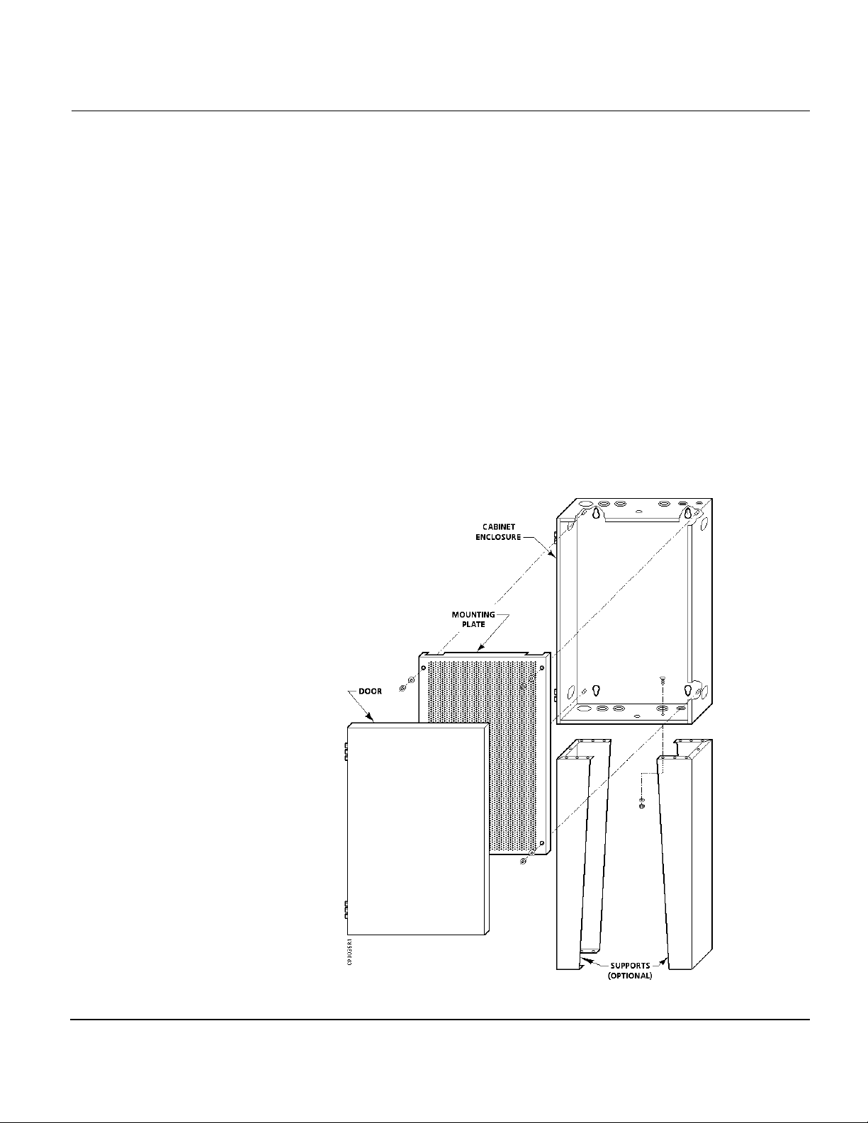
Figure 2. Wall Mount Cabinet Components.
Siemens Industry, Inc. Page 5
Page 6
Technical Instructions CP 567 Control Cabinets
Document Number 155-272P25
November 12, 2007
Cabinet Installation
(Flush Mount)
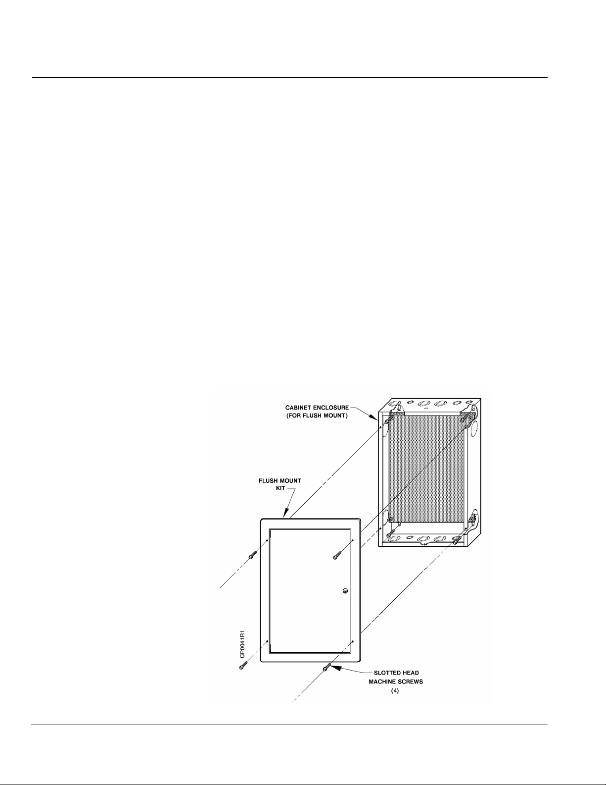
1. Mount the cabinet in a wall at least 6 inches (15.2 cm) deep. There are four keyhole
mounting holes in the back surface of the cabinet. Their sizes and locations are
shown in Figure 5. Use wall anchors that are suitable to support the weight of the
cabinet and its contents.
2. Determine the size of the knockouts required for the number and size of pneumatic
tubes and wires to be brought into the cabinet.
3. The cabinets are symmetrical before cutouts have been made, so the door can be
mounted with the hinge on the left or right side.
4. If more than one knockout is required, divide the tubes and wires for easy
connection to the controls.
5. If a cabinet light is required, order per instructions under accessories. The
recommended mini work light has a 2-inch diameter by 4-inch long (51 mm ×
102 mm) bulb holder on a 15-inch (381 mm) long flexible metal arm.
a. Remove the plug and mounting bracket from the light.
b. Punch out the 7/16-inch (11 mm) diameter knockout in the center of the top of
the cabinet.
c. Attach the light using the nut and washer provided with it.
d. Wire the light cord in compliance with local electrical codes.
Figure 3. Flush Mount Cabinet Components.
Page 6 Siemens Industry, Inc.
Page 7
CP 567 Control Cabinets Technical Instructions
(See Note 3)
Document Number 155-272P25
November 12, 2007
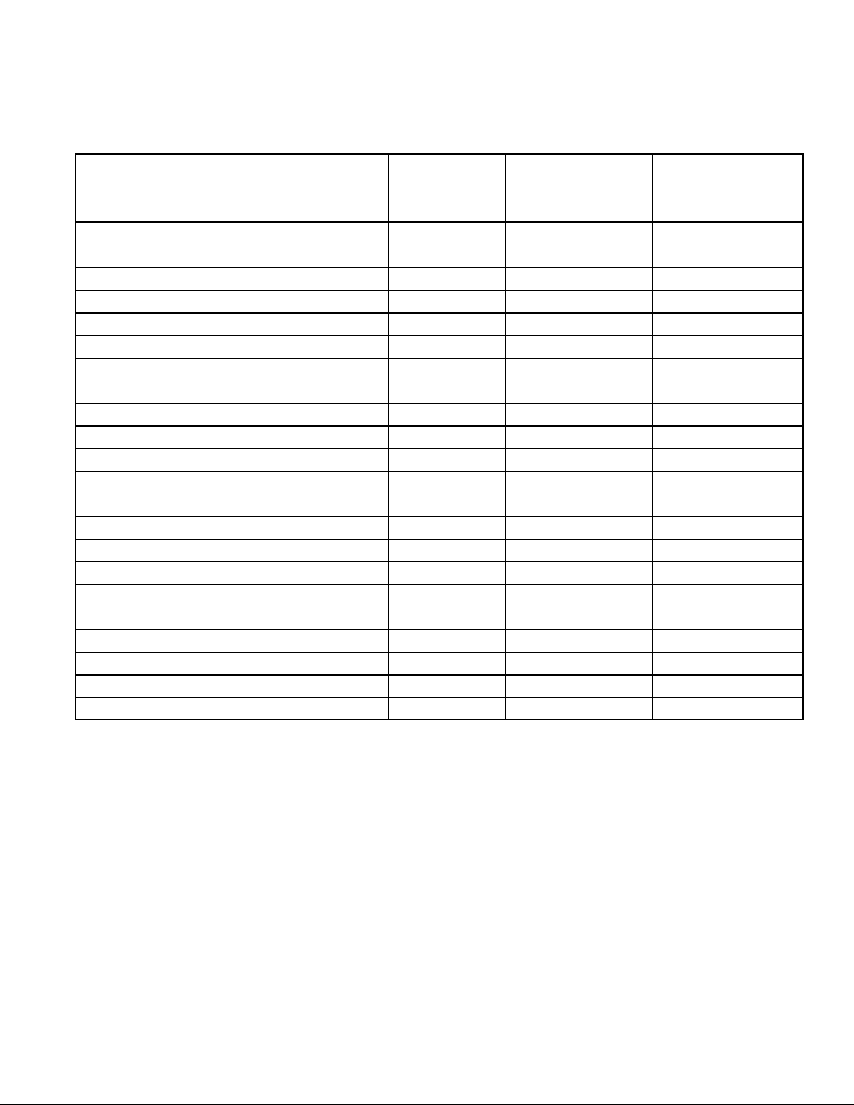
Table 4. Approximate Panel Space Requirem ents (Includes Fitting and Cl earances).
Equipment
Door Mounting
Depth
Inches (mm)
Equipment
Weight
Pounds (kg)
Mounting Plate
Depth
Inches (mm)
Inside Area Required
Inches
2
(cm2)
6 Input Sig. Selector – – 4 (102) 12 (77)
656 Pilot Valve – – 3 (76) 100 (645)
ARG 61.00 Wall Mount Case – – 8.52 (216.4) 13.10 (84.5)
ARG 61.01 Panel Mount Case 7.52 (191) 1.65 (0.750) – 11.28 (72.8)
D.P. Switch – – 3 (76) 45 (290)
Diff. Press. Reg. – – 3 (76) 35 (226) (See Note 1)
E.P. – – 1-1/4 (32) 30 (194)
Electric Relay – – 4 (102) 30 (194)
Enthalpy Comparator – – 3-1/2 (89) 30 (194)
FZA 21 Remote Setting Unit 0.87 (22) 0.11 (0.05) – 1.98 (12.76)
FZA 61 Remote Setting Unit 1.10 (28) 0.15 (0.07) – 3.00 (19.36)
Gauges 1-1/2" 2 (51) 0.2 (0.09) 1-1/2 (38) 4 (26) (See Note 2)
Gauges 2-1/2" 2-1/2 (64) 0.5 (0.22) – –
Gauges 3-1/2" 2-1/2 (64) 0.6 (0.27) – –
Min (PRV) 3 (76) 0.5 (0.22) 2 (51) 10 (65)
MP, BR, Analog Relays 4-1/2 (114) 2 (0.91) 2-1/2 or 5 (64 or 127) 42 (271)
P.E. (Single) – – 3-1/2 (89) 28 (181)
Positioning/Selector Switch 3 (76) 2 (0.91) 5 (127) 10 (65) (See Note 2)
PRV (Powers) – – 5-1/2 (140) 100 (645)
RC 195 – – 3-1/2 (89) 6 0(387)
Static Pressure Reg. – – 4 (102) 30 (194)
Switching Relay – – 2-1/2 (64) 65 (419)
NOTES: 1. Normally not mounted inside of the cabinet.
Siemens Industry, Inc. Page 7
2. If mounted inside of the cabinet.
3. Weights are given for door mounted devices only.
Page 8
Technical Instructions CP 567 Control Cabinets
Product
Cabinet
Inside Depth
Plate Inches (mm)
Maximum
Inches2 (cm2)
Maximum Number
Cabinet
Dual Knockouts
Type
Nominal Conduit Size
Inches (mm)
Knockout Diameter
Inches (mm)
Document Number 155-272P25
November 12, 2007
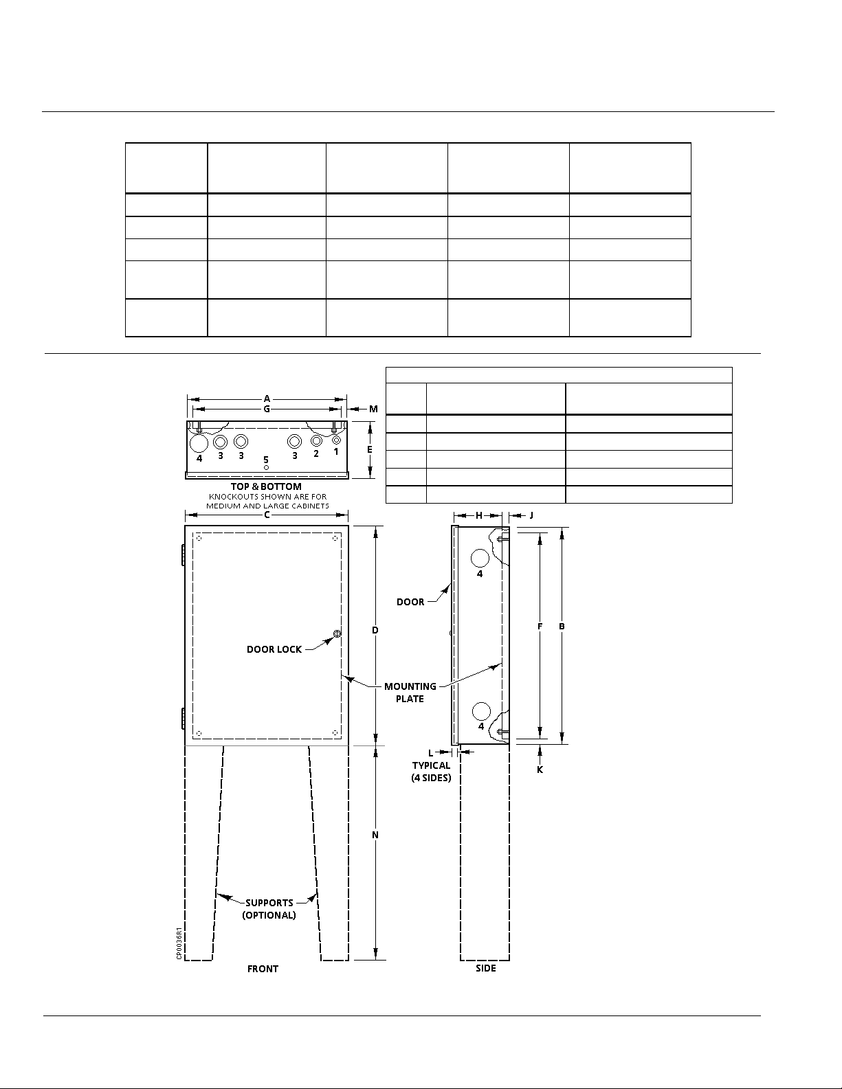
Table 5. Usability.
Numbers
Dimensions
Enclosure
Door to Mounting
Usable Area
of RC-195 Per
567-351 Size 1 5 (127) 172 (1109) 3
567-391 Flush Mount 4-5/8 (117) 172 (1109) 3
567-454 Size 2 5-1/2 (140) 227 (1465) 4
567-352
567-452
567-353
567-453
Size 3
Size 4
8-1/2 (216)
5-1/2 (140)
8-1/2 (216)
5-1/2 (140)
1 1/2 & 3/4 (13 & 19) 0.875 & 1.109 (22 &28)
2 3/4 & 1 (19 & 25) 1.109 & 1.375 (28 & 35)
3 1-1/4 & 1-1/2 (32 & 38) 1.734 & 1.984 (44 & 50)
4 2 (51) 2.469 (63)
5 – 0.437 (11)
380 (2451) 6
615 (3967) 10
Page 8 Siemens Industry, Inc.
Figure 4. Cabinet and Su p p o rt Dimensions (See Table 5 and Figure 9).
Page 9
CP 567 Control Cabinets Technical Instructions
Cabinet Assembly
Inches (mm)
Product
Size
A B C D E
F G H I J
5/16
5/16
Product
Number
Size
K L M N O
P Q R S –
Document Number 155-272P25
November 12, 2007
Dimensions,
Continued
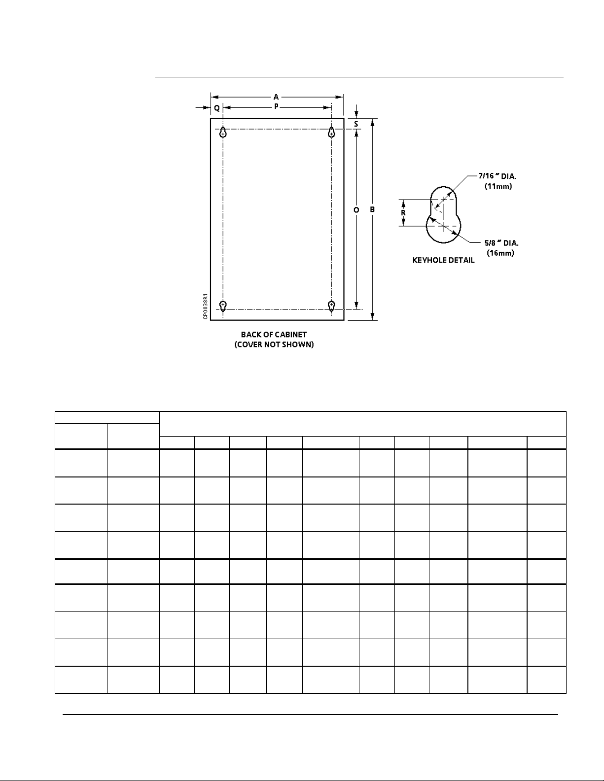
Figure 5. Rear View of Cabinet (See Table 6).
Table 6. Cabinet Assembly Dimensions (See Figures 4, 5, and 6).
Number
567-351 Size 1 16
(406)
567-454 Size 2 20
(508)
567-352
[567-452]
567-353
[567-453]
Size 3 24
(610)
Size 4 24
(610)
567-351 Size 1 2-1/4
(57)
567-454 Size 2 2-1/4
(57)
567-352
[567-452]
567-353
[567-453]
* See Figure 6 for dimensions of "N"
Size 3 2-1/4
(57)
Size 4 2-1/4
(57)
19
(483)
20
(508)
24
(610)
36
(914)
3/4
(19)
3/4
(19)
3/4
(19)
3/4
(19) 1 (25)
16-3/8
(416)
20-
(516)
24-3/8
(619)
24-3/8
(619)
5/8
(16)
1/2
(13)
1/2
(13)
19-1/2
(495)
20-
(516)
24-5/16
9-3/8(238)
(617)
36-1/2
9-3/8(238)
(927)
* 16-1/2
- 17.5
49
(1245)
37
(940)
Dimensions
5-3/4
(146)
6
(152)
[6 (152)]
[6 (152)]
(419)
(445)
21
(533)
33-1/2
(851)
14-1/2
(368)
(483)
19-1/4
(489)
31-1/2
(800)
13-1/2
(343)
19
14-3/4
(375) 5 (127)
15.25
(387)
23
(584)
22
(559)
1-1/4
(32)
12
(305) 4 (102)
16
(406) 4 (102)
16-314
(425)
3-5/8
(92)
5-3/8
(137)
8-1/2
(216)
8-1/2
(216)
1/2
(13)
1/2
(13)
1/2
(13)
1/2
(13)
5-11/16
(145)
5-7/8
(149)
9-1/4(235)
[5-7/8 (149)]
9-1/4(235)
[5-7/8 (149)]
1-1/4
(32)
1-1/4
(32)
1-1/2
(38)
1-1/4
(32)
1/2
(13)
1/2
(13)
1/2
(13)
1/2
(13)
–
–
–
–
Siemens Industry, Inc. Page 9
Page 10
Technical Instructions CP 567 Control Cabinets
Document Number 155-272P25
November 12, 2007
Dimensions,
Continued
Figure 6. Floor Mount Support Legs Kit.
Dimensions in Inches (mm).
Page 10 Siemens Industry, Inc.
Page 11
CP 567 Control Cabinets Technical Instructions
Your feedback is im port ant to us. If you have
Document No. 155-272P25
(See Table 7).
Dimensions in Inches (mm)
A*
B* F G I K M O
P Q S
T* U V
W*
X
Document Number 155-272P25
November 12, 2007
Dimensions,
Continued
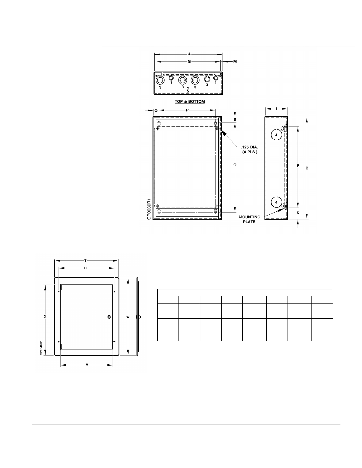
Figure 8. Flush Mount Door Dimensio n s
Figure 7. Flush Mount Cabinet Dimensions (See Table 7).
Table 7. Flush Mount Cabinet and Door Dimensions.
16-1/8
(410)
13-1/2
(343)
* Cutout dimensions; make cutout at least the size of dimensions A and B
(cabinet size) but no larger than T & W (door size).
19-1/2
(495)
1-1/4
(32)
13-1/2
(343)
1-1/4
(32)
14-3/4
(375)
18
(457)
5-1/8
(130)
15-7/16
(392)
1-1/2
(38)
14-3/4
(375)
1-11/16
(43)
21-3/8
(543)
16-1/2
(419)
18-1/8
(460)
Information in this publication is based on current s pecifications. The c ompany reserves the right to m ak e changes in specifications and models as
design improvements are introduced. Powers is a registered trademark of Siemens I ndus try, Inc. Product or c ompany names mentioned herei n
may be the trademarks of their respective owners. © 2007 Siemens Industry, Inc.
Siemens Industry, Inc.
Building Technologies Divis i on
1000 Deerfield Parkway
Buffalo Grove, IL 60089
+ 1 847-215-1000
comments about this document, pleas e send them to
Printed in the USA
Page 11
 Loading...