

Siemens 563-004,563-007,563-008 Installation Instructions Manual

Installation Instructions
Document No. 563-002
January 12, 2007
Wireless Fiel
d Level Network Transceiver (FLNX)
(Version 1.x)
Channel
Network I.D.
WLAN0001R1
Figure 1. Wireless Field Level Network Transceiver
F L N
(FLNX).
24 Vac 1.2VA
E H N
Accessories
563-027
Pre-terminated Cable Kit
(Includes two 14” cables:
power and com m unication )
Recommended for factory mounting
Warning/Caution Notations
WARNING:
Personal injury/loss of life may occur if you
do not follow the procedures as specified.
CAUTION:
Equipment damage or loss of data may
occur if you do not follow the procedures
as specified.
Expected Installation Time
Product Description
The Wireless Field Level Network Transceiver
(FLNX) is mounted at or near the FLN device
and is powered by 24 Vac. The antenna can be
mounted directly to the radio or mounted remotely for
installations where the location of the FLNX causes
the antenna to be shielded—for example, when the
FLNX is mounted inside a TEC enclosure.
Product Numbers
563-004 Wireless Field Level
Network Transceiver (FLNX)
(Version 1.x)
563-007 Direct Mount Antenna
563-008 Remote M ou nt Antenna
Transceivers do not come with antennas.
Antennas must be ordered se parately.
10 minutes
Required Tools and Materials
• Electro-static discharge wrist strap
•Smallflat-blade screwdriver
• Cordless drill/driver set
Prerequisites
• All wiring must conform to NEC and local
codes and regulations.
• 24 Vac Class II power source is available.
• Metal Oxide Varistors (MOVs) must be used
for TECs that switch high voltage devices. For
details, see th e FSN for Terminal Equipment
Controllers (TECs) Failing when Switching
High Voltage Powered Devices.
• Any application specific hardware or device
is installed.
tem N u m ber: 563-002, Rev. BA
I
age 1 of 4
P
Document No. 563-002
Installation Instructions
January 12, 2007
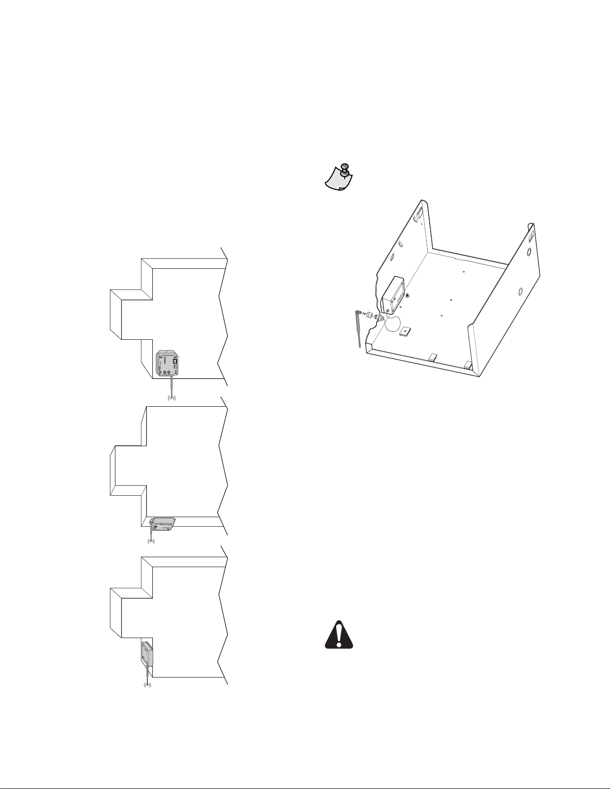
Antenna Mounting
Direct Mount Antenna
The preferred mounting configuration is to mount
the FLNX outside the TEC enclosure in a location
where it will establish the m ax imu m number of
communication links with other FLNXs and its
associated FPX. For example, in a VAV application
this will typically be on the bottom of the VAV box in
the ceiling plenum with the entire antenna extending
below the VAV box (Figure 2).
VAV BOX
Remote Mount Antenna
The FLNX is mounted inside the TEC (or any metal)
enclosure and the antenna is brought through a 1/2”
knockout (Figure 3).
The antenna extension cable is 12” long.
WLAN0016R1
Figure 3. FLNX Mounted Inside Enclosure.
VAV BOX
VAV BOX
WLAN0017R2
Figure 2. FLNX Mounting Options – No Enclosure.
Installation
1. Determine the optimal location of the FLNX and
antenna for RF communications.
Ideally, the antenna should extend below the VAV
box.
2. Mount the FLNX using the provided screws.
You can als o us e dou ble -sid ed tap e or VELCRO
fasteners.
3. Set the Channel and Network ID switches to the
settings selected for the WFLN.
4. Connect the communication port of the FLN
device to the FLNX (cable length limit is 4000 ft).
5. Connect to 24
CAUTION:
If the FLNX shares the power supply
with a Wireless TEC Transceiver ( TT X,
P/N 550-205) and the TEC, be sure to
useagroundisolatedtransformer(P/N
550-710) between the TTX and the power
transformer.
Vac power (Figu re 4).
®
Page 2 of 4 Siemens Building Technologies, Inc.
 Loading...