

Siemens 550-506, 550-507 Installation Instructions Manual
CE Compliant Dual Duct Controller — Two Air
Velocity Sensors — Electronic Output
Product Description
Required Tools
Installation Instructions
Document No. 550-308
Rev. 1, July, 2001
These instructions explain how to field install or
replace a CE Compliant Dual Duct Controller — Two
Air Velocity Sensors — Electronic Output with or
without Autozero Modules.
Shipping carton includes a controller assembly
(controller board and cover), a mounting rail, Autozero
Modules with brackets (optional), and two self-tapping
screws.
For CE compliance, ferrite filter(s) and an alternate
room sensor cable must be used (see Product
Numbers).
NOTE: Keep the controller assembly in its static-proof
bag until installation.
Product Numbers
Product Description
550-506 Dual Duct Controller — Two Air Velocity
Sensors — Electronic Output
550-507 Dual Duct Controller — Two Air Velocity
Sensors — Electronic Output with Autozero
Modules
588-100A 25-ft (7.6-m)
588-100B 50-ft (15.2-m)
588-100C
550-705 clamp-on ferrite filter 10 pack
2-RJ11 room
temperature
sensor cable
100-ft (30.48-m)
Caution Notation
CAUTION:
Equipment damage or loss of
data may occur if the user
does not follow procedure as
specified.
• Electro-Static Discharge (ESD) wrist strap
• Small flat-blade screwdriver
• Medium flat-blade screwdriver
• Medium-duty electric drill
• 1/4-inch (6.35 mm) hex nut bit
• Portable Operator’s Terminal with Controller
Interface Software (CIS) Rev. 2.0 or higher
(controller replacement only)
Additional tools needed if not using self-tapping
option:
• 1/4-inch (6.35 mm) hex nut driver
• 1/8-inch (3 mm) bit
Prerequisites
• Room temperature sensor installed (optional)
• Air velocity sensors installed in ducts
• 24 Vac Class 2 power source
• Supply power to the unit is OFF
• Autozero Modules with brackets are on hand
(optional)
• If required, controller enclosure installed
Expected Installation Time
New controller installation 10 min.
Replacement with removable terminal
blocks
Replacement without removable
terminal blocks
NOTE: You may require additional time for
database work at the field panel.
6 min.
16 min.
Page 1 of 9
Document Number 550-308
Installation Instructions
Rev. 1, July, 2001
COVER
24 V-A C
C H GND
DO1
NO C
1 2 3 4 5 6 7 8 9 10 11 12 13 14 15 16 17 18 19 20
DO2
NO C
DO3
NO C
DO4
NO C
DO5
NO C
DO6
NO C
DO7
NO C
DO8
NO C
AIR VELOCITY
HI
DI3
DI2
AI3
SENSOR PORTS
LO
HI
BST
FLN TRUNK
+ - S
RX TX
LO
RTS
CONTROLLER
BOARD
MOUNTING
HOLE
(2)
MOUNTING
RAIL
1 2 3 4 5 6 7 8 9 10 11 12 13 14 15 16 17 18 19 20
DO LEDS
INPUT / OUTPUT TERMINATIONS
TEC0321R1
H
C
E
POWER
TRUNK
TERMINATIONS
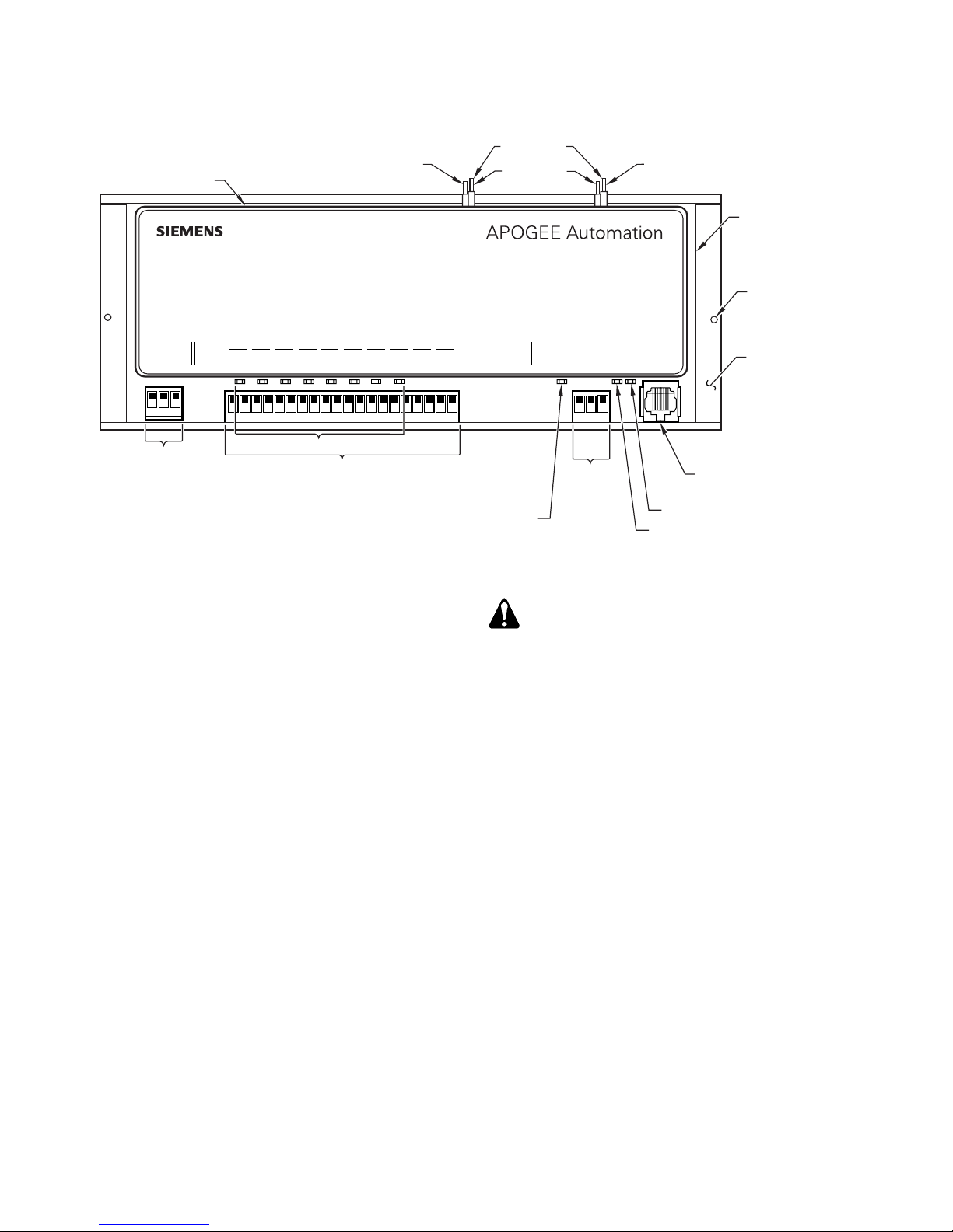
Figure 1. CE Compliant Dual Duct Controller — Two Air Velocity Sensors without Autozero Modules.
New Installation Instructions
1. Using the mounting rail as a template (Figure
1), mark the screw holes where you will install
the controller assembly.
2. Do one of the following:
• If using the self-tapping screws provided:
Using the drill and the hex nut bit, fasten the
mounting rail.
• If not using the self-tapping screws: Drill
two 1/8-inch (3 mm) pilot holes, then fasten
the mounting rail with No. 6 or No. 8 screws.
3. Place the ESD wrist strap on your wrist and
attach it to a good earth ground.
4. Carefully remove the controller assembly from
the anti-static bag. Center it over the mounting
rail and snap it securely into place.
5. Connect the Floor Level Network (FLN). See
Figure 4.
6. Connect the point wiring as shown in Figure 7.
NOTE: Wiring to DI3/AI3 requires a clamp-on
ferrite filter (Figure 6). Strain relief must be
provided to ensure long-term effectiveness
due to added weight of the filter.
-
+
S
BST LED
FLN
TRUNK
TERMINATIONS
ROOM TEMPERATURE
TRANSMIT LED
RECEIVE LED
SENSOR / MMI PORT
CAUTION:
The Controller’s Digital Outputs (DOs)
control 24 Vac loads only. The maximum
rating is 12 VA for each DO. Use an
interposing 220V 4-relay module for any of
the following:
• VA requirements higher than
maximum.
• 110 or 220 Vac.
• DC power.
• Separate transformers used to
power the load.
NOTES: 1. Each DO provides a Normally Open (NO)
and a Common (C) terminal. Terminate
both connections of a 24 Vac load directly
to the controller board. Actuators use two
DOs and require three connections.
2. The 24 Vac “H” terminal is switched
through a TRIAC to the NO terminations
when the associated DO is energized.
7. If using Autozero Modules, refer to the
Installation Instructions (540-199), which are
included.
8. After the Autozero Modules are installed,
connect the Autozero Module wires to the
controller at DO7.
Page 2 of 9 Siemens Building Technologies, Inc.

Document Number 550-308
Installation Instructions
Rev. 1, July, 2001
9. After viewing Figure 6, install a clamp-on ferrite
filter on the room temperature sensor cable and
plug the cable into the RTS port on the controller
(Figure 1). Use only an approved 588-100 series
cable as described in the Product Numbers
section. Consider strain relief to ensure longterm effectiveness due to added weight of the
filter.
10. Connect the power trunk as shown in Figure 5.
DO NOT apply power to the controller.
11. Connect the tubing from the air velocity sensor
pickups to the HI and LO ports on the controller,
or on the Autozero Modules (if present). Make
sure that the “HI” and the “LO” pressure sides of
the sensors are connected to the corresponding
“HI” and “LO” sensor ports on the controller or
Autozero Modules (Figure 2).
The installation is complete.
Replacement Instructions
CAUTION:
Replacement of a TEC requires you to
record, re-enter, or update the initial point
values of the controller being replaced.
These are the points marked with an
asterisk (*) on the CIS display.
a. Obtain a field panel Point Definition
Report for the LCTLR point. Record the
values in Table 1.
b. View the initial value block. (This
information is valid only since the last
update was made). Record the values in
Table 1.
c. Delete the LCTLR point from the field
panel.
3. Replace the old controller as follows:
a. Remove power from the controller.
b. If the old controller has the RTS plug
between the FLN and point terminations,
disconnect the wires from the power trunk
terminal block. If the old controller has the
RTS plug on the opposite end of the board
from the power trunk terminal block, remove
the power trunk terminal block.
c. Remove, in order, the controller’s:
• FLN terminal block
• Point wiring
• Room temperature sensor
d. Remove the old controller assembly from the
mounting rail.
NOTE: CIS Rev. 2.0 or higher is required for
controller replacement.
1. Place the ESD wrist strap on your wrist and
attach it to a good earth ground.
2. Before disconnecting the old controller, do one
of the following:
NOTE: If the new controller has a newer
firmware revision than the old
controller, skip to the third bullet.
• If the old controller communicates with the
field panel, update the controller initial values
at the field panel.
• If the old controller does not communicate
with the field panel, but communicates with
CIS, or is stand-alone, record the initial
values in Table 1.
• If the old controller is not communicating or
has a newer firmware revision, use the
following steps to update the field panel:
e. Carefully remove the new controller
assembly from the anti-static bag. Center it
over the mounting rail and snap it securely
into place.
f. If the old controller has the RTS plug
between the FLN and point terminations,
remove all terminal blocks (except the power
trunk) from the new controller. If the old
controller has the RTS plug on the opposite
end of the board from the power trunk
terminal block, remove all terminal blocks.
g. Plug, in order, the controller’s:
• Pre-wired FLN
• Point wiring
NOTE: Wiring to DI3/AI3 requires a clamp-on
ferrite filter (Figure 6). Strain relief
must be provided to ensure long-term
effectiveness due to added weight of
the filter.
Siemens Building Technologies, Inc. Page 3 of 9
 Loading...