

Siemens 941, 942, 546-00750A, 546-00750AE, 546-00750BE Installation Instructions Manual
Installation Instructions
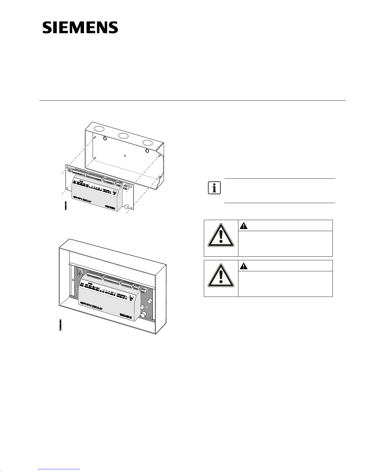
CE Compliant Fume Hood Control le r —
and mounting rail
546-00705E
CE Compliant Fume Hood Controller
enclosure
NOTE:
proof bag until you are ready to install.
WARNING
Personal injury/loss of life may
occur if you do not follow the
procedures as specified.
CAUTION
Equipment damage or loss of data
may occur if you do not follow the
procedures as specified.
Document No. 546-00085
December 8, 2011
Application 941 and 942
Figure 1. CE Compliant Fume Hood
Controller(Standard enclosure).
Product Numbers
546-00705
Keep the controller board in its static
Warning/Caution Notation
CE Compliant Fume Hood Controller
— Application 941 and 942 with cover
— Application 941 and 942 with FHC
Figure 2. CE Compliant Fume Hood Controller
(Otherenclosure).
Control Applications
941 and 942
Product Description
The Fume Hood Controller Board (Figure 1 and
Figure 2) is the main termination board for the Fume
Hood Controller. The board comes with a ferrite filter
to suppress electrical emissions from the 8-
conductor cable. The ferrite filter must be installed to
meet FCC requirements and CE compliance
Item No. 546-00085. Rev. CA Page 1 of 7
Expected Installation Times
23 minutes.
Required Tools and Materia ls
• Smallflat-blade screwdriver
Prerequisites
• Fume Hood Controller Enclosure is mounted
and wiring has been roughed-in.
• Operator Display Panel is instal led and
cable pulled to location of controller.
Document No. 546-00085
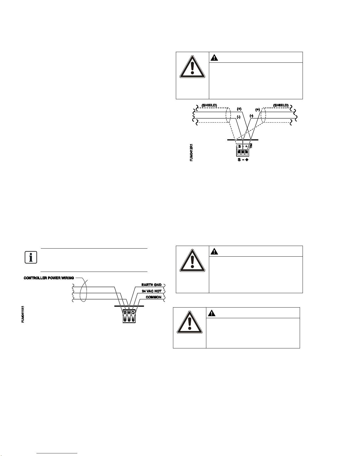
NOTE:
enclosuremust be grounded.
CAUTION
Do not connect an earth ground
to prevent ground loop currents.
CAUTION
The Fume Hood Controller DOs
interposing relay must be used.
CAUTION
is not FCC and CE compliant.
Installation Instructions
December 8, 2011
Instructions
1. If the Fume Hood Controller will be used with a
field panel, then disconnect the Field Level
Network (FLN) trunk from the field panel.
2. Place the ESD wrist strap on your wrist and
attach it to a good earth ground.
3. Carefully remove the controller board from the
anti-static bag.
4. To mount the controller, do one of the following:
• Center the controller board over the
mounting posts in the bottom of the
controller enclosure (Figure 1). Insert the
corner holes of the board onto the mounting
posts. Press firmly on the board to snap it
securely into place. Repeat for all
controllers.
• Secure the mounting rail inside the
enclosure at the controller’s desired
location and snap it into place on the
mounting rail (Figure 2). Repeat for all
controllers.
5. After installing all controller boards, verify that
power is OFF. Connect a certified 24 Vac Class
II power source to the Fume Hood Controller,
see Figure 3.
to the FLN trunk shield terminal.
The earth ground should be
connected only at the field panel
Figure 4. FLN Trunk Wiring.
8. Connect the point wiring for the appropriate
Fume Hood Controller application as shown in
Figure 7 and Figure 8. The wiring for sashes is
shown in Figure 9 through Figure 14. Red/Signal
and Black/Common polarity must be maintained
on all sash sensors. Terminate both connections
of a 24 Vac load directly to the controller board.
The 24 Vac “H” terminal is switched through a
triac to the NO terminations when the associated
DO is energized.
To meet CE requirements, the
Figure 3. Power Trunk Wiring.
6. Connect the FLN trunk wiring as shown in
Figure 4.
7. After all controllers are connected to the FLN
reconnect the FLN trunk to the field panel.
Page 2 of 7 Siemens Industry, Inc.
control 24 Vac loads only. The
maximum rating is 12 VA for
each DO. For higher ratings an
9. Follow the instructions in Figure 5.
Ferrite filter(s) must be installed
on the Operator Display Panel
(ODP) cable. If not, the controlle r
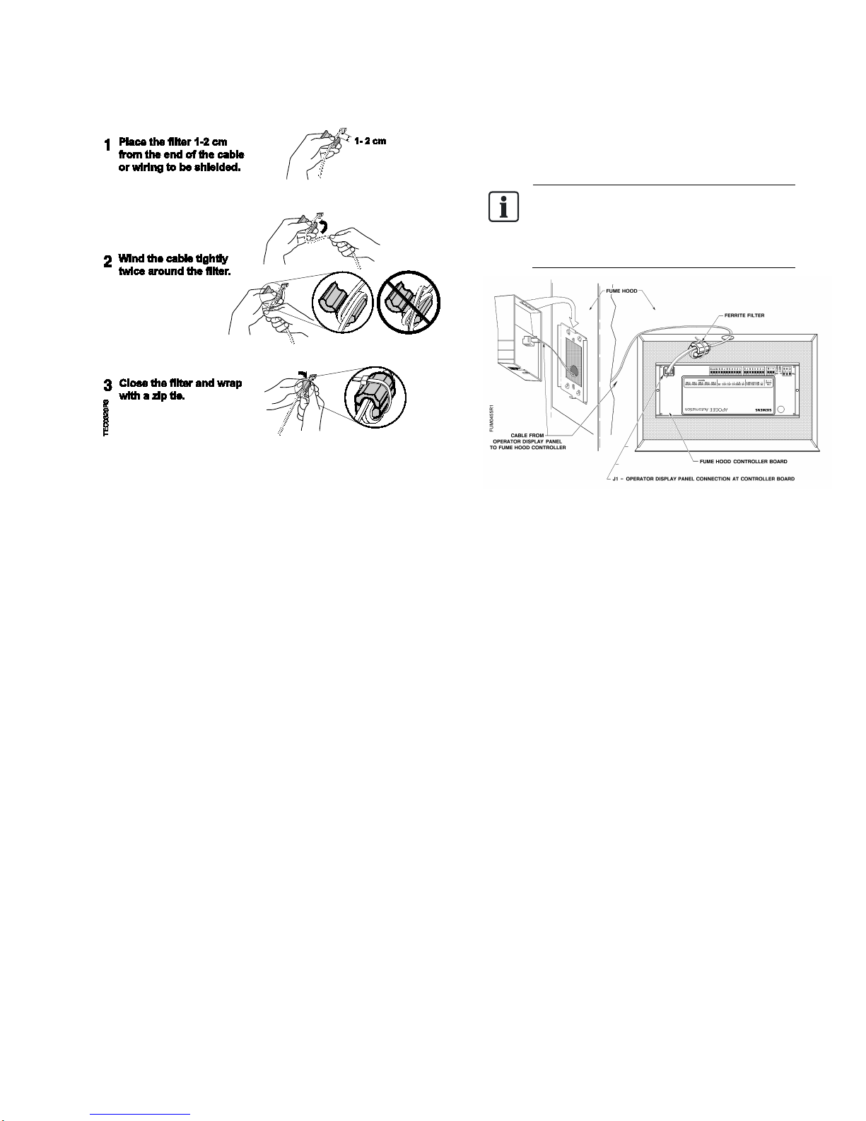
Figure 5. Installing a Ferrite Filter.
NOTE:
Document No. 546-00085
Installation Instructions
December 8, 2011
10. Plug the Operator Display Panel cable into the
Operator Display Panel Communication port on
the controller board (Figure 6 and Figure 7).
The ferrite filter must be installed on the
cable inside the enclosure to meet FCC
and CE requirements (
Figure 6).
Figure 6. Ferrite Filter Installed.
The installation is complete.
Siemens Industry, Inc. Page 3 of 7
 Loading...