

Siemens 546-00303A Installation Instructions Manual
Fume Hood Monitor
Product Description
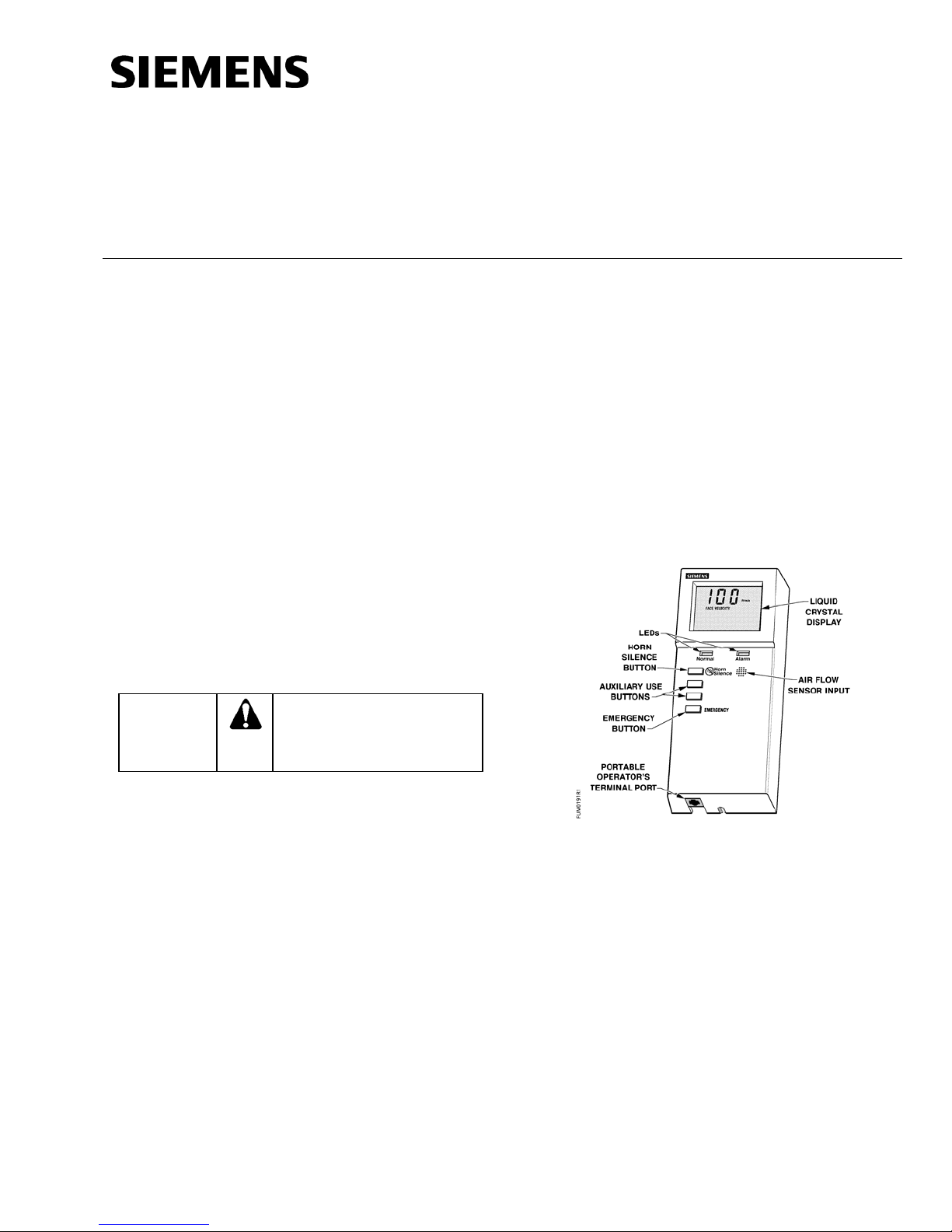
The Fume Hood Monitor (FHM) (Figure 1) provides
visual and audible alarms to alert a fume hood user
of airflow conditions. The mounting plate is designed
for fume hoods with or without existing cutouts. This
kit contains:
• Fume Hood Monitor with mounting plate
• Three removable wire connectors
• Four sheet metal screws
• Two machine screws
• 2 ft. (0.6 m) air sensor hose
• Plastic sidewall adapter and lock ring
Installation Instructions
Document No. 546-00310
November 15, 2006
Expected Installation Time
27 minutes
Prerequisites
• Power cable in place
If using a field panel:
• Floor Level Network (FLN) cable from the
field panel to the FHM in place
If using an external alarm or auxiliary DI
connection:
• External alarm or auxiliary DI cable from
source to FHM in place
Product Numbers
546-00303A Fume Hood Monitor
546-00303B Fume Hood Monitor mounting plate
Warning/Caution Notations
CAUTION:
Equipment damage or loss of
data may occur if the user
does not follow procedure as
specified.
Required Tools
For a fume hood with an existing cutout:
• Medium-duty electric drill
• 1/2-inch. (13.0 mm) drill bit
• Small flat-blade screwdriver
• Small Philips screwdriver
• Wire strippers
For a fume hood without an existing cutout:
• Medium-duty electric drill
• 1/8-inch (3.0 mm) drill bit
• 1/2-inch (13.0 mm) drill bit
• Metal-cutting saw or 3/ 4 in. and 1 in. drill bits
or hole saws
• Small flat-blade screwdriver
• Small Philips screwdriver
• Wire strippers
Figure 1. Fume Hood Monitor.
Instructions
NOTE: Mount the FHM so that the fume hood
operator can easily read its display and
can easily reach its buttons. This height is
approximately 4-1/2 ft. to 5 ft.
(1.4 to 1.5 m) from the floor.
1. Choose the mounting location for the FHM. The
FHM should be mounted directly on the fume
hood and can be mounted over a pre-existing
cutout on the fume hood. See Figure 2 for
installation clearance requirements.
Page 1 of 6
Document No. 546-00310
Installations Instructions
November 15, 2006
Mounting Plate Installation with an
Existing Cutout
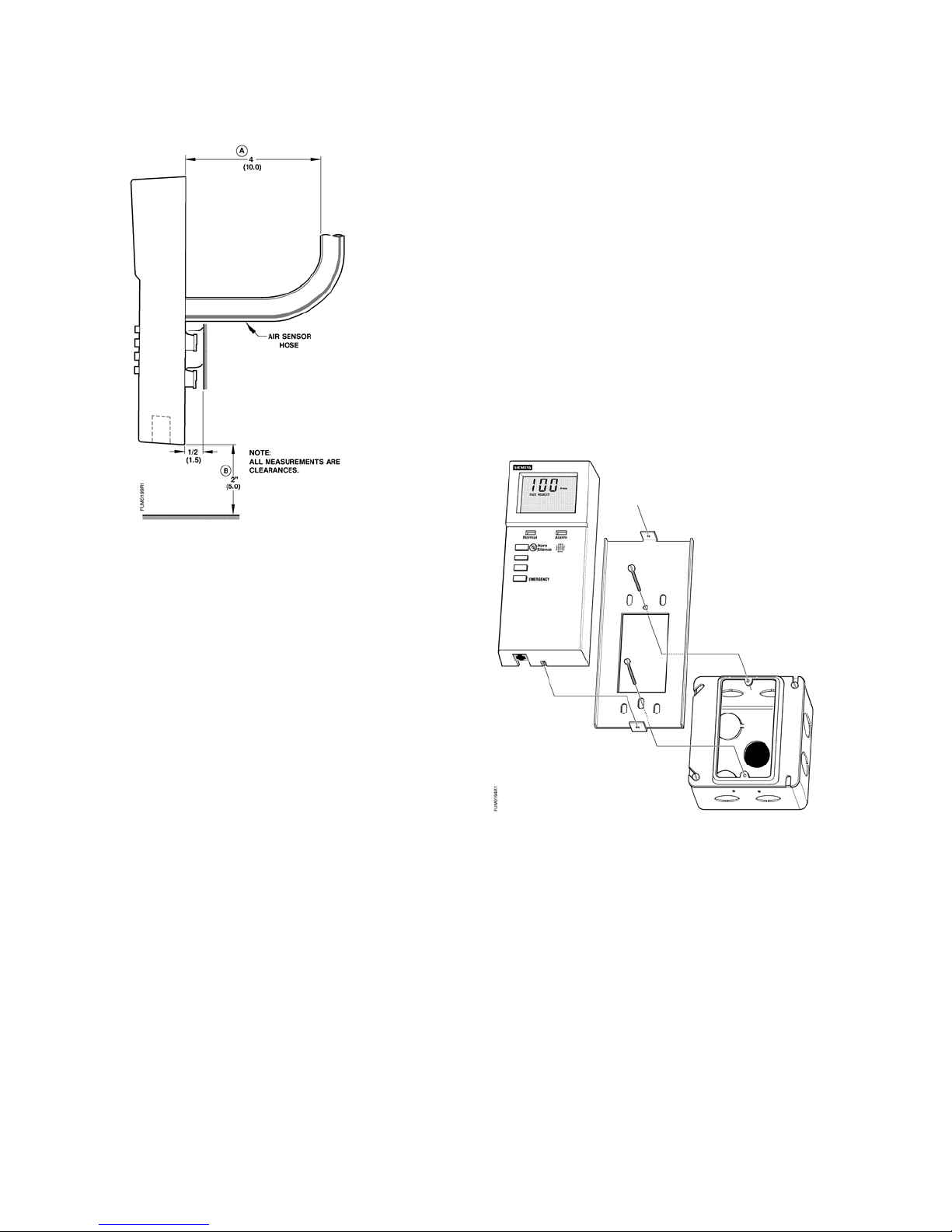
1. See Figure 3. If the fume hood is provided with a
2 inch × 4 inch (5.0 × 10.0 cm) cutout with an
electric utility box, then use the provided
machine screws to attach the mounting plate to
the electric utility and skip to Sidewall Hole
Mounting.
If the fume hood has no electric utility box,
make sure that the cutout provides enough
clearance for the air sensor hose and to
connect the power, FLN, external alarm, and
auxiliary DI wires. Then continue to Step 2.
Figure 2. Installation Clearance Requirements.
NOTE: Clearance is needed to prevent the sensor
air hose from bending or kinking, and to
insert the Portable Operator’s Terminal
Cable.
2. Confirm that an earth ground is connected to the
mounting plate. To do this, make sure that the
following conditions are met:
a. The conduit junction box is grounded, or
b. The fume hood enclosure is grounded, or
c. A separate wire is connected between the
earth ground and the mounting plate.
3. Continue with one of the following mounting
methods: Mounting Plate Installation with an
Existing Cutout or Mounting Plate Installation
without an Existing Cutout.
Figure 3. Installation with an Existing Cutout.
2. Position the bracket over the opening and mark
the locations of the two mounting holes.
3. Using the 1/8-inch (3.0 mm) drill bit, drill the two
mounting holes.
4. Using the screws provided, attach the mounting
plate to the mounting surface.
Page 2 of 6
Siemens Building Technologies, Inc.
5. Proceed to Sidewall Hose Mounting.
 Loading...