

Siemens 540-716, 540-717, 540-514N Installation Instructions Manual

Installation Instructions
Room Pressuriz ation Controller
–
Pneumatic
Output
CAUTION:
Document No. 540-1032
May 3, 2017
Product Description
These instructions explain how to field install (pages
1 through 3) or replace (pages 3 through 4) a Room
Pressurization Controller – Pneumatic Output with or
without Autozero Modules.
Product Number
540-716 Room Pressurization Controller –
Pneumatic Output
540-717 Room Pressurization Controller –
Pneumatic Output with Autozero
Modules
540-514N Room Pressurization Controller
Board – Pneumatic Output
(replacement)
Shipping carton includes a pre-assembled metal
enclosure with controller board and cover, pneumatic
output modules, Autozero Modules with brackets
(optional), and four self-tapp ing/drilling screws.
Installation Conventions
Equipment damage or
loss of data may occur if
you ds not follow
procedures as specified.
Required To ols
Prerequisites
• (Optional) Room temperature sensor
installed
• Air velocity sensors installed in ducts
• A source of 24 Vac Class 2 power available
• Supply power to the unit is OFF
• An air supply line is available at the controller
Expected Installation T ime
New controller installation 10 minutes
Replacement (old controller has
removable terminal blocks)
Replacement (old controller does
not have removable terminal
blocks)
NOTE: You may require additional time for
database work at the field panel.
6 minutes
16 minutes
New Installation Instru ctions
NOTE: These steps only refer to new installations.
For replacement instructions, refer to pages 3-4. For
Autozero Module installation, refer to instruction
540-199.
The following tasks can be performed by the
electrician:
• Electro-Static Discharge (ESD) wrist strap
• Small flat-blade screwdriver
• Medium flat-blade screwdriver
• Medium-duty electric drill
• 1/4 in. (6.35 mm) hex nut bit
• Portable Operator’s Terminal with Controller
Interface Software Rev. 2.0 or later (required
for controller replacement only)
Additional tools needed if not using self-tapping
option:
• 1/4 in. (6.35 mm) hex nut driver
• 1/8 in. (3 mm) bit
Item Number: 540-1032, Rev. FA Page 1 of 7
1. Loosen, but do not remove, the cover screws
and remove the enclosure cover. Using the rear
panel of the enclosure as a template (Figures 1
and 2), mark the location for the four screw
holes where you will install the enclosure.
2. Do one of the following:
• If using the self-tapping screws: Using
the drill and the hex nut bit, start the
screws. (Screws do not require starter
holes.)
• If not using the sel f-tapping screws: Drill
four
1/8 in. (3 mm) pilot holes for the screws.
Using the hex nut driver, start the screws.
Document Number 540-1032
CAUTION:
CAUTION:
Installation Instructions
May 3, 2017
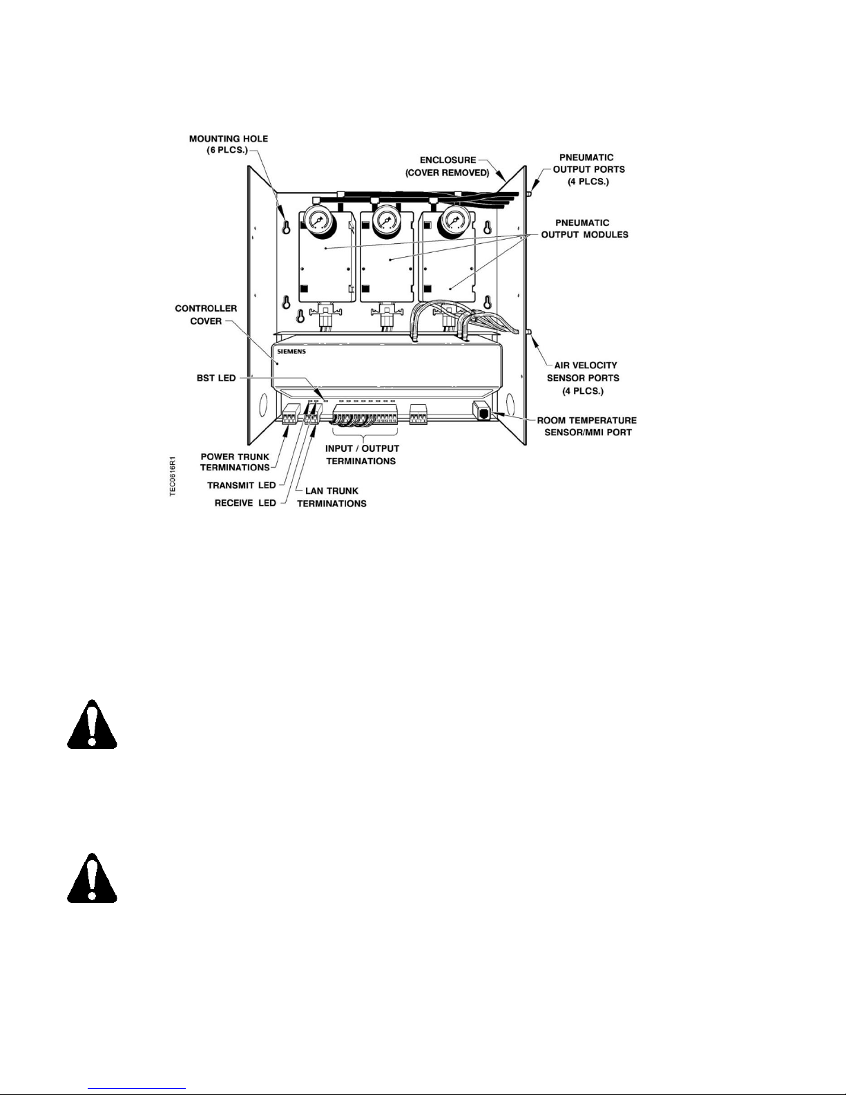
Figure 1. Room Pressurization Controller – Pneumatic Output without Autozero Modules.
3. Mount the enclosure on the screws and tighten
them down with either the drill or hex nut driver.
4. Remove the appropriate knockouts.
5. Place the ESD wrist strap on your wrist and
attach it to a good earth ground.
6. Connect the Local Area Network (LAN) trunk
(Figure 4). Run the wiring through knockout.
NOTE: Each DO provides a Normally Open
(NO) and a Common (C) terminal. Terminate
both connections of a 24 Vac load directly to the
controller board.
NOTE: The 24 Vac “H” terminal is switched
through a TRIAC to the NO terminations when
the associated DO is energized.
8. If using a pressure mode switch, then follow the
Room Pressurization Controller (RPC) Pressue
Mode Switch nstallation Instructions (540-719)
Do not connect an earth ground to
the Shield (S) terminal.
7. Connect the point wiring for the appropriate
application. See Figure 7. See Table 1 for
application descriptions. Run the wiring through
knockout.
included with the switch.
9. After the pressure mode switch is installed, wire
the switch to DO8 and AI3 as described in the
instructions.
10. Plug the Room Temperature Sensor cable into
the RTS port on the controller board. See
Figure 1. Run the cable through knockout.
11. Connect the power trunk as shown in Figure 5.
The Controller’s Digital Outputs (DOs)
control 24 Vac loads only. The
maximum rating is 12 VA for each DO.
For higher VA requirements, 110 or
220 Vac requirements, separate
DO NOT apply power to the controller. Run the
wiring through knockout.
12. Replace the enclosure cover and tighten the
cover screws.
transformers used to power the load,
or DC power requirements, use an
interposing 220 V 4-relay module
(TEC Relay Module P/N 540-147).
Page 2 of 7 Siemens Industry, Inc.

Document Number 540-1032
CAUTION:
Installation Instructions
May 3, 2017
The following task can be performed by the fitter:
13. Connect the tubing from the air velocity sensor
pickups to the HI and LO ports outside of the
enclosure. The supply pickup goes to the supply
AVS ports, and the exhaust pickup goes t o the
exhaust AVS ports on the side of the enclosure.
Make sure that the “HI” and the “LO” pressure
sides of the sensors are connected to the “HI”
and “LO” sensor ports on the controller
(Figure 1) or Autozero Modules (Figure 2). Refer
to Table 2 for air velocity sensor connections.
The installation is complete.
Replacement Instructions
Replacement of a TEC requires you
to record, re-enter, or update the
initial point values of the controller
you are replacing. These are the
points marked with an asterisk (*)
on the Controller Interface Software
(CIS) display.
NOTE: CIS Rev. 2.0 or later is required for controller
replacement.
The following tasks can be performed by the system
specialist:
1. Place the ESD wrist strap on your wrist and
attach it to a good earth ground.
2. Before disconnecting the old controller, do one
of the following:
NOTE: If the new controller has a newer
firmware revision than the old controller, then
skip to the third bullet.
• If the old controller communicates with the
field panel, then update the controller init ial
values at the field panel.
• If the old controller does not communicate
with the field panel, but communicates with
the CIS, or if the controller is stand-alone,
then record the initial values (those marked
with an asterisk (*) on the CIS display).
Record the values.
• If the old controller is not communicating at
all, or if the controller you are installing has a
newer firmware revision than the old
controller, then while at the field panel,
follow these steps:
a. Obtain a field panel P oint Definition
Report for the LCTLR point. Record the
values.
b. View the initial value block. (This
information is valid only since the last
update was made). Record the values.
c. Delete the LCTLR point from the field
panel.
3. Replace the old controller as follows:
The following tasks can be performed by the
electrician:
a. Remove power from the controller.
b. If the old controller has the RTS plug
between the LAN trunk and point
terminations, then disconnect the wires
from the power trunk terminal block. If the
old controller has the RTS plug on the
opposite end of the board from the power
trunk terminal block, then remove the
power trunk terminal block.
c. Remove, in the following order, the
controller’s:
• LAN trunk terminal block
• DO8, AI3, and DI2 only
• room temperature sensor
d. Loosen, but do not remove, the mounting
screws.
e. Lift and remove the old enclosure.
f. Mount the new enclosure on the mounting
screws and tighten them down with either
the drill or hex nut driver.
g. Remove the appropriate knockouts.
h. If the old controller has the RTS plug
between the LAN trunk and point
terminations, then remove all terminal
blocks (except the power trunk) from the
new controller. If the old controller has the
RTS plug on the opposite end of the board
from the power trunk terminal block, then
remove all terminal blocks.
Siemens Industry, Inc. Page 3 of 7
 Loading...