

Page 1
Duct Temperature Sensor,
10K Ohm Thermistor
Product Description
The single point 10K ohm Duct Temperature Sensor
is inserted into the duct to provide an input to the
controller. The assembly may be installed on the
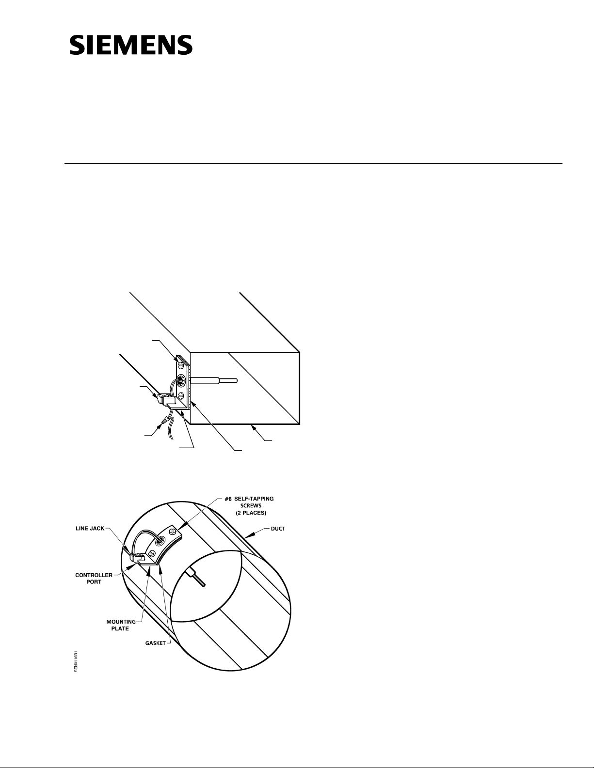
outside of a square or round duct (Figures 1 and 2).
The mounting plate is made of thin steel, which can
be easily bent to conform to round or irregular
contour ducts.
#8 SELF-TAPPING
SCREWS (2 PLACES)
Installation Instructions
Document No. 538-494
Rev. 3, October, 2001
Contents
Shipping carton includes sensor assembly with line
jack and gasket, and two No. 8 self-tapping screws.
Product Number
540-128
Required Tools
•
Medium-duty electric drill with 3/8-inch
(9.5 mm) and 1/8-inch (3 mm) drill bits
•
Power screwdriver with 1/4-inch hex
extension or medium, flat-bade screwdriver
Additional tools if NOT using preterminated cables:
LINE JACK
2 WIRE
CONNECTOR
MOUNTING
SEN0281R1
Figure 1. Installation on a Square Duct.
PLATE
GASKET
DUCT
•
Room sensor connector tool 540-140
•
Room sensor connector kit 540-141
(100/pkg)
Expected Installation Time
12 minutes
Prerequisites
•
Review the instructions befor e begi nning.
•
Appropriate field wiring must be in place.
NOTE:
All wiring must compl y with Nationa l
Electrical Code (NEC) and local regulations.
Installation
1. Drill a 3/8-inch (9.5 mm) diameter hole on the
side of the duct where the sensor is to be
mounted.
NOTE:
If you cannot use the self-tapping feature of
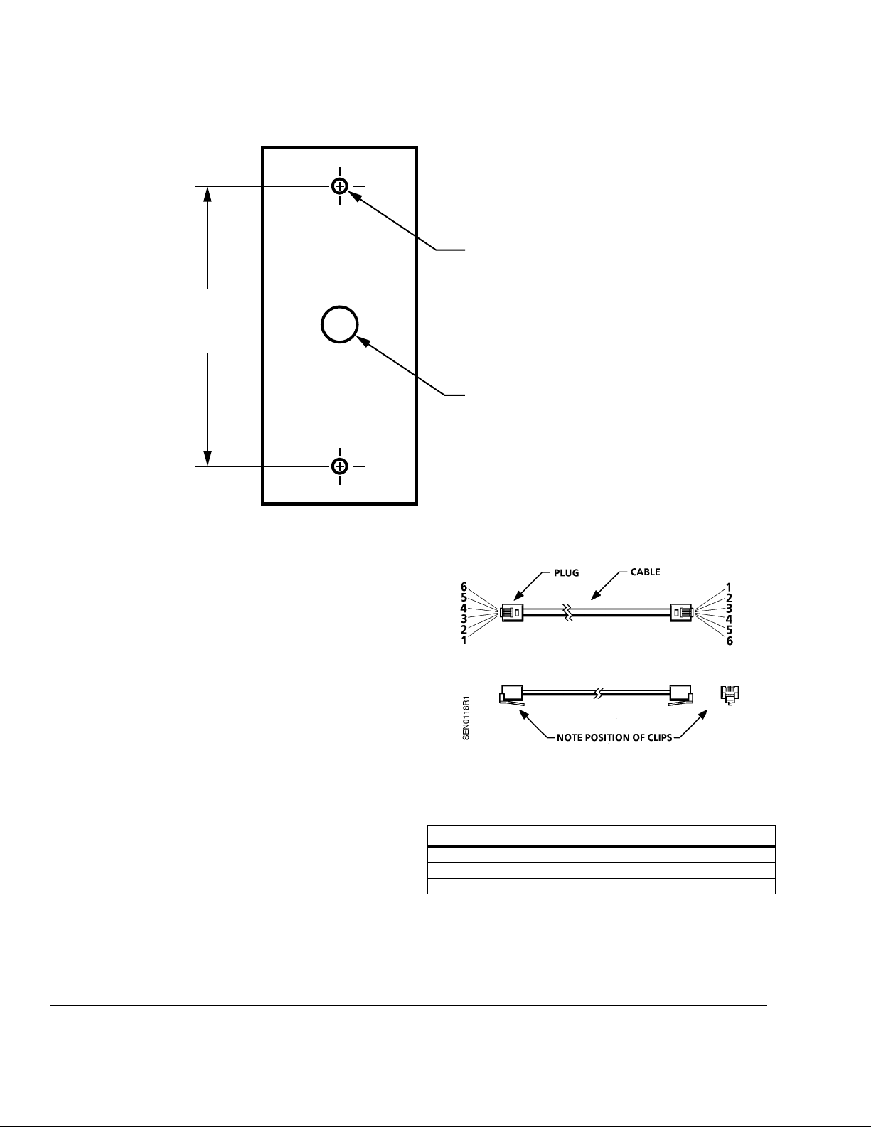
the screws provided, use Figure 3 as a
template and drill one 3/8-inch (9.5 mm)
center hole and two 1/8-inch (3 mm)
diameter holes in the side of the duct.
Figure 2. Installation on a Round Duct.
Page 1 of 2
Page 2
Document No. 538-494
Installation Instructions
Rev. 3, October, 2001
2-3/4"
(70 mm)
1/8" (3 mm) DIA. HOLE
(2 PLACES)
3/8" (9.5 mm) HOLE
SEN0114R1
Figure 3. Template for Mounting Holes.
2. Insert the sensor into the 3/8-inch (95 mm) hole
in the duct.
3. Secure the sensor assembly to the duct with the
two No. 8 self-tapping screws provided.
4. Press the line jack into the cutout on the
mounting plate. See Figures 1 and 2.
5. Do one of the following:
•
If you are using preterminated cable, skip to
Step 7.
•
Using the room sensor connector tool,
attach an RJ11 connector to both ends of
the cable. Align the six wires in the same
order on the connectors on both ends of the
cable. See Figure 4 and Table 1.
6. Insert the RJ11 plug of the field wiring into the
line jack.
7. Connect the field wiring to the controller by
inserting the RJ11 plug into the controller's port.
Figure 4. Wiring Pairs.
Table 1. Wiring Pairs.
Pin Wire Color/Stripe Pin Wire Color/Stripe
1 Green/white 4 White/blue
2 Orange/white 5 White/orange
3 Blue/white 6 White/green
The installation is now complete.
Information in this publication is based on current specifications. The company reserves t he right to make changes i n specifications and
models as design improvements are introduced. Other product or company names mentioned herei n m ay be the trademarks of their
respective owners. © 2001 Siemens Building Technologies, Inc.
Siemens Building Technologies, Inc.
1000 Deerfield Parkway
Buffalo Grove, IL 60089-4513
U.S.A.
Your feedback is important to us. If you have
comments about this document, please send
them to [email protected]
Document No. 538-494
Printed in the U.S.A.
Page 2 of 2
 Loading...