


Contents
Contents
Safety precautions . . . . . . . . . . . . . . . . . . . . . . . . . . . 5
Notes on secure operation . . . . . . . . . . . . . . . . . . . . 5
Your contribution to the environment (ECO) . . . . . 5
The Gigaset PC Card 54 . . . . . . . . . . . . . . . . . . . . . . . 7
Wireless LAN Basics . . . . . . . . . . . . . . . . . . . . . . . . . . . . . . . . . . . . . . . . . . . . . . . . . . . . 7
Local Area Network (LAN) . . . . . . . . . . . . . . . . . . . . . . . . . . . . . . . . . . . . . . . . . . . . 7
Ad-hoc network . . . . . . . . . . . . . . . . . . . . . . . . . . . . . . . . . . . . . . . . . . . . . . . . . . . . 8
Infrastructure network . . . . . . . . . . . . . . . . . . . . . . . . . . . . . . . . . . . . . . . . . . . . . . . 8
Security in wireless networksEncryption . . . . . . . . . . . . . . . . . . . . . . . . . . . . . . . . . . . . 9
WEP encryption . . . . . . . . . . . . . . . . . . . . . . . . . . . . . . . . . . . . . . . . . . . . . . . . . . . . 9
WPA encryption . . . . . . . . . . . . . . . . . . . . . . . . . . . . . . . . . . . . . . . . . . . . . . . . . . . . 9
Range of wireless communication via a WLAN . . . . . . . . . . . . . . . . . . . . . . . . . . . . . . . 9
Installing the Gigaset PC Card 54 . . . . . . . . . . . . . . 10
System requirements . . . . . . . . . . . . . . . . . . . . . . . . . . . . . . . . . . . . . . . . . . . . . . . . . . 10
Contents . . . . . . . . . . . . . . . . . . . . . . . . . . . . . . . . . . . . . . . . . . . . . . . . . . . . . . . . . . . . 10
Notes on location . . . . . . . . . . . . . . . . . . . . . . . . . . . . . . . . . . . . . . . . . . . . . . . . . . . . . 10
Status displays . . . . . . . . . . . . . . . . . . . . . . . . . . . . . . . . . . . . . . . . . . . . . . . . . . . . . . . 11
Installation procedure . . . . . . . . . . . . . . . . . . . . . . . . . . . . . . . . . . . . . . . . . . . . . . . . . 12
Running installation . . . . . . . . . . . . . . . . . . . . . . . . . . . . . . . . . . . . . . . . . . . . . . . . 12
Connecting the Gigaset PC Card 54 . . . . . . . . . . . . . . . . . . . . . . . . . . . . . . . . . . . . 14
Installing driver software . . . . . . . . . . . . . . . . . . . . . . . . . . . . . . . . . . . . . . . . . . . . 15
Checking installation . . . . . . . . . . . . . . . . . . . . . . . . . . . . . . . . . . . . . . . . . . . . . . . . . . 16
Reading the connection quality from the icon . . . . . . . . . . . . . . . . . . . . . . . . . . . 17
Configuring Gigaset PC Card 54 . . . . . . . . . . . . . . . 18
The Gigaset WLAN Adapter Monitor . . . . . . . . . . . . . . . . . . . . . . . . . . . . . . . . . . . . . . 18
Opening the monitor . . . . . . . . . . . . . . . . . . . . . . . . . . . . . . . . . . . . . . . . . . . . . . . 18
Deactivating Autostart . . . . . . . . . . . . . . . . . . . . . . . . . . . . . . . . . . . . . . . . . . . . . . 19
Operating the Gigaset WLAN Adapter Monitor . . . . . . . . . . . . . . . . . . . . . . . . . . . 19
Closing the monitor . . . . . . . . . . . . . . . . . . . . . . . . . . . . . . . . . . . . . . . . . . . . . . . . 20
Configuration . . . . . . . . . . . . . . . . . . . . . . . . . . . . . . . . . . . . . . . . . . . . . . . . . . . . . . . . 21
Configuration – General . . . . . . . . . . . . . . . . . . . . . . . . . . . . . . . . . . . . . . . . . . . . 21
Configuration – Security . . . . . . . . . . . . . . . . . . . . . . . . . . . . . . . . . . . . . . . . . . . . 24
Configuration – Profile . . . . . . . . . . . . . . . . . . . . . . . . . . . . . . . . . . . . . . . . . . . . . . 28
Status . . . . . . . . . . . . . . . . . . . . . . . . . . . . . . . . . . . . . . . . . . . . . . . . . . . . . . . . . . . . . .30
IP settings . . . . . . . . . . . . . . . . . . . . . . . . . . . . . . . . . . . . . . . . . . . . . . . . . . . . . . . . . . .31
Site Monitor . . . . . . . . . . . . . . . . . . . . . . . . . . . . . . . . . . . . . . . . . . . . . . . . . . . . . . . . . 33
About . . . . . . . . . . . . . . . . . . . . . . . . . . . . . . . . . . . . . . . . . . . . . . . . . . . . . . . . . . . . . .35
3

Contents
Uninstalling Gigaset PC Card 54 . . . . . . . . . . . . . . . 36
Uninstalling the software . . . . . . . . . . . . . . . . . . . . . . . . . . . . . . . . . . . . . . . . . . . . . . 36
Completing Uninstall . . . . . . . . . . . . . . . . . . . . . . . . . . . . . . . . . . . . . . . . . . . . . . . . . . 36
Updating device drivers . . . . . . . . . . . . . . . . . . . . . 37
Glossary . . . . . . . . . . . . . . . . . . . . . . . . . . . . . . . . . . 38
Appendix . . . . . . . . . . . . . . . . . . . . . . . . . . . . . . . . . . 45
Trouble shooting . . . . . . . . . . . . . . . . . . . . . . . . . . . . . . . . . . . . . . . . . . . . . . . . . . . . . 45
Specifications . . . . . . . . . . . . . . . . . . . . . . . . . . . . . . . . . . . . . . . . . . . . . . . . . . . . . . . . 48
Software . . . . . . . . . . . . . . . . . . . . . . . . . . . . . . . . . . . . . . . . . . . . . . . . . . . . . . . . . 48
Hardware . . . . . . . . . . . . . . . . . . . . . . . . . . . . . . . . . . . . . . . . . . . . . . . . . . . . . . . . 48
Approval . . . . . . . . . . . . . . . . . . . . . . . . . . . . . . . . . . . . . . . . . . . . . . . . . . . . . . . . . . . . 49
Service (Customer Care) . . . . . . . . . . . . . . . . . . . . . . . . . . . . . . . . . . . . . . . . . . . . . . . 50
Guarantee Certificate United Kingdom . . . . . . . . . . . . . . . . . . . . . . . . . . . . . . . . . . . . 50
Guarantee Certificate Ireland . . . . . . . . . . . . . . . . . . . . . . . . . . . . . . . . . . . . . . . . . . . 51
Index . . . . . . . . . . . . . . . . . . . . . . . . . . . . . . . . . . . . . 53
4

Safety precautions
Safety precautions
u The tic can affect medical equipment. Therefore, you should pay attention to the
technical conditions of the corresponding environment.
u Make sure you include the operating instructions and the CD-ROM, when you pass
on your Gigaset PC Card 54 to somebody else.
u Dispose of the Gigaset PC Card 54 and any CD-ROMs you no longer need in an envi-
ronmentally-friendly manner.
u Under no circumstances try to use a damaged device. If in doubt, please contact our
service department, see Chapter "Service (Customer Care)" on page 50.
Notes on secure operation
When you have installed and configured the Gigaset PC Card 54 on your PC, you should
perform security settings on the wireless network:
u Change the SSID for all of the wireless devices within your network (see "SSID (Serv-
ice Set Identifier)" on page 22).
u Encrypt the communication over your wireless network (see "Configuration – Secu-
rity" on page 24).
Your contribution to the environment (ECO)
We at Gigaset Communications GmbH make our products as environmentally compatible as possible. Our goal is a sustainable process that makes it
easier for us to comply with the strict stipulations of the ISO standard 14001
for international environmental management.
Further advantages for the ecology
u Thanks to a switched-mode power supply, all our routers and repeaters use up to
60% less power and so offer higher energy efficiency.
u You can reduce the WLAN's transmitting power for all routers and repeaters and
some WLAN clients – depending on the device in question and your PC's operating
system.
u You can turn off the WLAN completely.
5

Your contribution to the environment (ECO)
Trademarks
Gigaset Communications GmbH is a trademark licensee of Siemens AG.
Microsoft, Windows 98SE, Windows ME, Windows 2000, Windows XP and Internet
Explorer are registered trademarks of the Microsoft Corporation.
Please remember:
Trademarks and trade names used in these instructions are meant only to describe the
operating steps and this use does not imply that they are freely available. Trademarks
and trade names are the property of the corresponding holder of the rights.
6

The Gigaset PC Card 54
The Gigaset PC Card 54
The Gigaset PC Card 54 is a 54 Mbps WLAN network adapter that is connected to your
PC or Notebook via a PCMCIA slot. You can use Gigaset data products to set up a wireless
local network (WLAN = Wireless Local Area Network) without having to lay cables.
Your Gigaset PC Card 54 can be used to connect your PC to other PCs equipped with
wireless network adapters (ad-hoc mode).
You can also connect your PC to a wireless router, e. g. to the Gigaset SE505 dsl/cable,
for Internet access (infrastructure mode).
Since the PCs communicate with each other via radio, it does not matter where they are
located, as long as they are within range of the wireless network. Mobile PCs, such as
Notebooks, can connect to the WLAN even after changing location. This enables you to
use all the files and printers on the network. The Gigaset PC Card 54 works according to
the IEEE 802.11g transmission standard and is backwards compatible with the older
standard IEEE 802.11b. For network security, wireless transmission can be encrypted
using 64/128-bit WEP or the newer WPA standard.
These operating instructions contain important information on how to set up a WLAN
and to configure your Gigaset PC Card 54.
Wireless LAN Basics
This section provides basic information on wireless LANs to show the role of the
Gigaset PC Card 54 in setting up a wireless network
Local Area Network (LAN)
A LAN is a network that exists in a limited area. A network is two or more computers
which are connected together in order to share files as well as peripheral devices,
e. g. a printer.
Using the Gigaset PC Card 54 you can communicate with other PCs without having to
route network cable. Thus you can take your computer to another place and still remain
connected to the network.
You can use the Gigaset PC Card 54 in two different ways. On the one hand, you can
establish a connection to one or more PCs equipped with wireless network adapters.
This is an ad-hoc network. On the other hand, you can establish a connection to an
Access Point, which is used to obtain access to an already existing wired LAN (infrastructure network).
7

The Gigaset PC Card 54
Ad-hoc network
In an ad-hoc network, PCs communicate with each other via wireless peer-to-peer connections. An ad-hoc network is set up by participants as and when required. All the PCs
must have a wireless network adapter installed, e. g. a Gigaset PC Card 54, a
Gigaset USB Adapter or USB Stick 54 or a Gigaset PCI Card 54. Ad-hoc networks are used
wherever communication networks have to be set up quickly without any existing network infrastructure and the participants are mobile.
Infrastructure network
In an infrastructure network, connections between network participants are set up via
an Access Point (or several Access Points). The Access Point provides the basis for the
wireless network. It controls the connections between the participants and can also
establish the connection from the mobile stations of a wireless network to a wired LAN
(Ethernet) or the Internet.
Roaming
Several Access Points can be installed to extend the range of a wireless network. Participants in the wireless network can move freely between the various Access Points without losing contact to the network. As soon as there is a risk of losing contact, the PC
automatically looks for another Access Point with a stronger signal. All Access Points and
wireless network adapters must have the same SSID. All Access Points must be connected to the same Ethernet network.
8

The Gigaset PC Card 54
Security in wireless networksEncryption
Any network, be it wired or wireless, is exposed to the risk of eavesdropping.
Connecting your local network to the public network exposes your data and applications
to not inconsiderable risks. As with an individual connection, you should always protect
your network PCs against external attacks, e. g. via emails, with a virus scanner.
These virus scanners however do not provide any protection against unauthorised
access from outside (hackers). To counter this risk, Gigaset data products offer various
encryption procedures that largely rule out unauthorised access (hacking) to your wireless network.
WEP encryption
WEP encryption (Wired Equivalent Privacy) encodes data for sending using a key that
you have defined. Once they reach the recipient, who uses the same key, the data are
restored to the state before you sent them. Recipients who do not know this key cannot
read the content of this data stream or only after a great deal of effort.
There are two security levels for calculating the encryption key:
u 64-bit mode
u 128-bit mode
WPA encryption
Wireless Protected Access (WPA) is a new standard-compliant solution for greater security in wireless networks. WPA is meant to replace the existing WEP standard (Wired
Equivalent Privacy) and offers more reliable encryption and authentication methods.
With your Gigaset PC Card 54 you can use WPA encryption regardless of the operating
system used. WPA encryption is particularly recommended where the highest security
is required.
Range of wireless communication via a WLAN
The range is up to 300 m in the open. In buildings, the maximum range is up to 30 m.
The operating environment, the nature of the rooms and building may reduce the range
considerably. You can boost the range of your wireless network by placing a repeater,
e. g. a Gigaset WLAN Repeater, at the limit of its range.
9

Installing the Gigaset PC Card 54
Installing the Gigaset PC Card 54
System requirements
For operation, you will require:
u a PC with at least 466 MHz and one of the following operating systems:
Windows 98SE, Windows ME, Windows 2000 or Windows XP
u 64 MB RAM, more working memory is recommended
u at least 30 MB free hard disk space
u a free PC card slot (Cardbus)
u a CD-ROM drive or a DVD drive
Contents
The package contains the following components:
u a Gigaset PC Card 54
u a CD-ROM containing installation and configuration software, detailed operating
instructions, Adobe Reader to read the operating instructions and the document
"Practical tips and configuration examples".
u a Quick Installation Guide
Notes on location
Choose the location of the PC where the Gigaset PC Card 54 will be connected with the
fewest obstacles to radio waves. Protect the Gigaset PC Card 54 from dampness.
The PC with the Gigaset PC Card 54 should not be placed in the immediate vicinity of
other electronic equipment. Electrical equipment can mutually affect each other, and
radio waves may impair the functioning of other devices.
If your PC with the Gigaset PC Card 54 should be under a desk or in a housing, the range
of the wireless network can be affected. For the best possible range, we recommend
placing the WLAN components in a central and an open location.
10

Installing the Gigaset PC Card 54
Status displays
There are two status displays (LEDs) on the Gigaset PC Card 54 . They are used to display
the:
u Operating status (PWR), red
u Transmission status (ACT), green
LED State Meaning
PWR
ACT
Continuously lit
Off The device is not ready for use.
Flashing Data is being transmitted.
Off There is currently no data traffic.
The Gigaset PC Card 54 was installed successfully on
your PC and is ready for operation.
11

Installing the Gigaset PC Card 54
Installation procedure
Please remember:
Do not insert the Gigaset PC Card 54 into a PCMCIA slot on your PC until the installation software prompts you to do so.
First, the software included in the scope of delivery must be installed. This software not
only includes the driver software for the device, it can also be used as a configuration
and monitoring tool, the Gigaset WLAN Adapter Monitor
Only this software has been written especially for the Gigaset PC Card 54. There are similar drivers available in the Windows driver database. But, as a rule, such drivers do not
fully cover all the features or function in a different manner.
Do not connect the Gigaset PC Card 54 to your PC until prompted by the installation program. If you connect the Gigaset PC Card 54 to your PC before installing the software,
Windows will automatically recognise the device and show the dialog box prompting for
the appropriate driver. Click on Cancel to close the dialogue. Remove the Gigaset PC
Card 54 from the PC and install the software.
Please remember:
You may require administrator rights for the installation process on your PC.
Information for users with Windows 98SE/ME:
If you are prompted to restart your computer during installation, click on Restart.
After this, installation continues automatically.You should now follow the instructions
and steps shown below.
Have your Windows Installation CD on hand. You may be prompted to insert it.
Running installation
ì Close all running programs.
ì Insert the CD-ROM supplied into the CD-ROM drive of your PC and wait until the wel-
come screen appears. If this screen does not appear automatically, start installation
manually:
– Open Windows Explorer.
– Select the CD-ROM drive.
– Double-click start.exe.
The language selection screen appears
ì Select the language.
You will now see a screen showing the contents of the CD-ROM.
12
Installing the Gigaset PC Card 54
Installation Install the software for your Gigaset PC Card 54.
User guide This opens the detailed operating instructions on
the CD-ROM. If you cannot open the detailed operating instructions on the CD-ROM, you will have to
install the free Adobe Reader.
Practical Tips and
Configuration Examples
Install Adobe Reader Install Adobe Reader, Version 6.
Browse CD If you are looking for a particular file on the
Back The program returns to the language selection
Exit This closes the program.
Here you will find solutions to various problems.
CD-ROM, you can display the CD-ROM contents
in an Explorer window.
screen.
ì Click on Installation.
Note:
The screens for the various operating systems differ only marginally. Installation is
largely automatic, apart from a few mouse clicks and restarts.
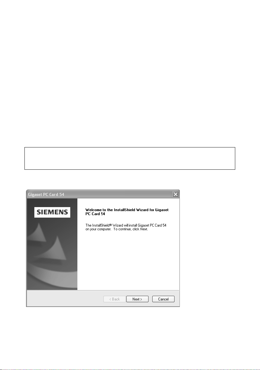
The InstallShield Wizard appears.
ì Click on Next to continue installation.
The licence agreement screen now appears.
ì If you accept the licence agreement, click on Yes.
13
Installing the Gigaset PC Card 54
In the next screen, choose the directory for the installation.
ì Click on Browse, if you want to select another directory. Click on Next to continue
installation.
During installation, the InstallShield Wizard uses the screen Setup progress to show
which action is being carried out, and the progress is also displayed.
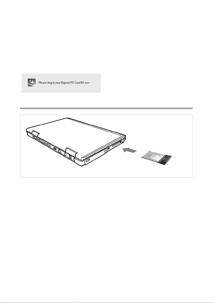
After this stage of installation is completed, a message appears prompting you to connect the Gigaset PC Card 54 to your PC.
Connecting the Gigaset PC Card 54
ì Insert the Gigaset PC Card 54 in the PCMCIA slot on your PC.
14
Installing the Gigaset PC Card 54
Installing driver software
Once the Gigaset PC Card 54 has been plugged in, installation continues automatically.
The operating system's automatic hardware recognition opens to install the drivers for
the Gigaset PC Card 54.
ì Depending on the other settings for your PC, an additional dialog box may appear.
Select the Install software automatically option, and click on Next.
If the window does not appear, the installation step described here is automatically carried out by the system.
Please remember:
u Under Windows 98SE / ME:You may be prompted to insert your Windows Installa-
tion CD to continue driver installation. Therefore you should have this CD handy
or enter the path name where the Windows installation files are stored on your PC.
u Restart your PC if you are prompted to do so.
u If your PC already contains more recent files, answer the question whether you
want to keep them with YES.
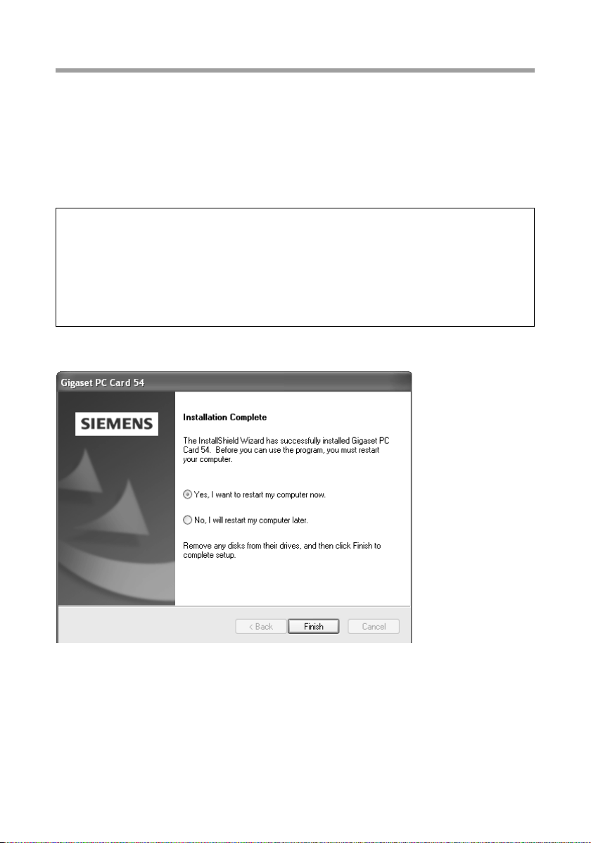
After installation, a message will appear prompting you to complete installation.
ì Click on Finish.
This closes the installation program. Depending on the Windows operating system version you are using, you may also be requested to restart your PC.
15
Installing the Gigaset PC Card 54
Checking installation
If installation was successful, you can now use the Gigaset WLAN Adapter Monitor. With
the Gigaset WLAN Adapter Monitor you can configure your Gigaset PC Card 54 and create a connection to other network adapters or an Access Point.
The Gigaset WLAN Adapter Monitor is represented by an icon in the status area of the
taskbar, this icon shows you if there is a connection to a connection partner and the
quality of the connection. In a wireless network using only Gigaset products and where
th e st and ard setting s we re used (e. g . no enc rypt ion ), t he c onn ect ion to an Ac cess Po int
is set up automatically during installation.
The following may be displayed in the status area of the taskbar:
The Gigaset WLAN Adapter Monitor icon is not displayed.
ü
ì First try to open the Gigaset WLAN Adapter Monitor
manually, see Chapter "Opening the monitor" on
page 18.
If this fails, then something went wrong during installation.
ì Deinstall the software, see Chapter "Uninstalling the
software" on page 36.
ì Then install the software again, see Chapter "Running
installation" on page 12.
The Gigaset WLAN Adapter Monitor icon is displayed in the
taskbar, with a red ball above the icon:
The Gigaset WLAN Adapter Monitor is installed; the Gigaset
PC Card 54 has not been inserted or inserted incorrectly.
ì Check that the card is correctly positioned.
The Gigaset WLAN Adapter Monitor icon is displayed in the
taskbar, with a red cross above the icon:
The Gigaset WLAN Adapter Monitor is installed and active;
there is no connection to the local network.
ì Turn to Chapter "Configuring Gigaset PC Card 54" on
page 18.
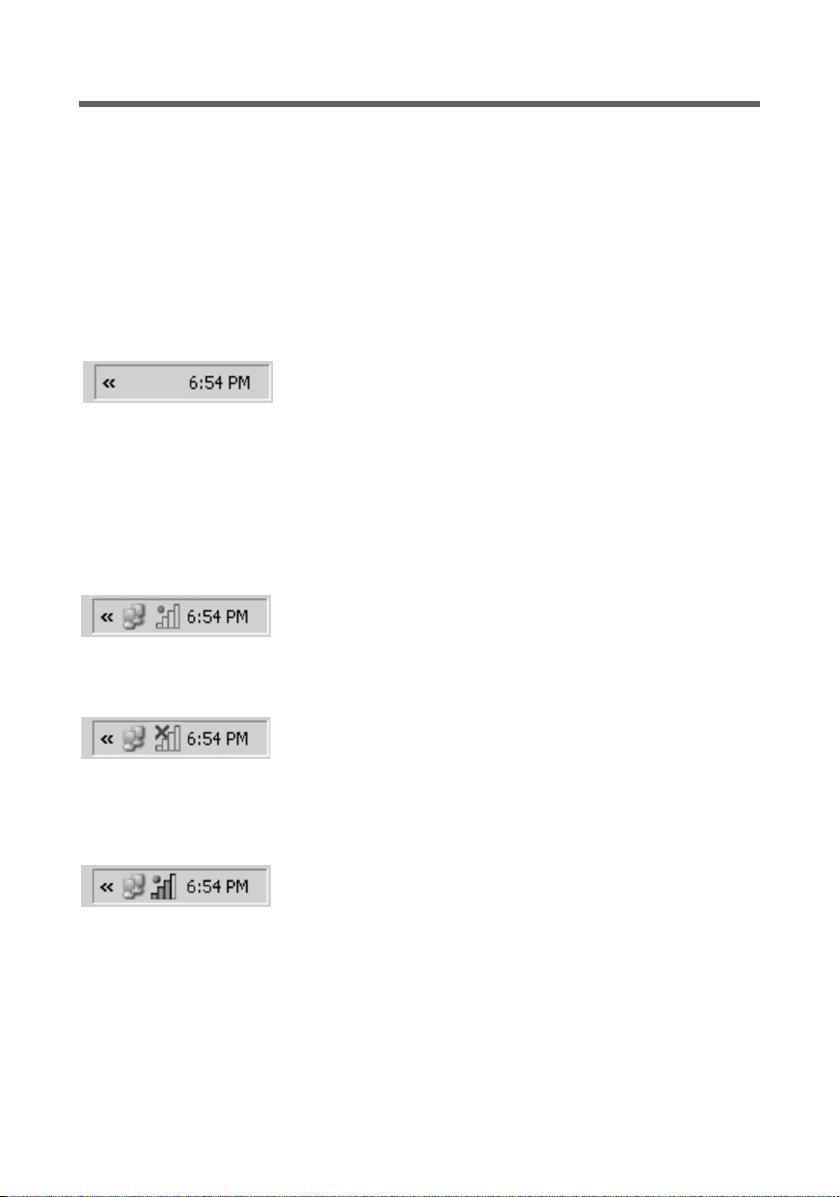
The icon is displayed in the taskbar, with a green ball above
the icon:
The Gigaset WLAN Adapter Monitor is installed and active;
there is no connection to the local network. The number of
bars displayed in the icon shows the connection quality.
You are advised to read Chapter "Notes on secure operation" on page 5.
16

Installing the Gigaset PC Card 54
Displaying QuickInfo for the connection
If you point the mouse over the icon in the taskbar, you will see a small window that
displays the connection properties.
The following properties are shown:
u SSID (Service Set Identifier) in the Connection line
u the transmission rate (in Mbps) in the Speed line
u the transmission quality (in %) in the Link quality line
If there is no connection, you will see a red cross over the icon and in QuickInfo, Disconnected is displayed.
Reading the connection quality from the icon
The icon changes gradually depending on the current connection quality. The better the
connection quality, the higher the transmission speed
With reasonable to poor connection:
ì If possible, move your PC closer to the connection partner for greater field strength.
No WLAN available (red cross over bar)
There is no WLAN within range of your Gigaset PC Card 54 that you could
connect to.
ì Check the configuration of the Access Point and adjust the Gigaset PC
Card 54 settings accordingly.
Or
ì Change your location to reduce the distance to a connection partner.
17

Configuring Gigaset PC Card 54
Configuring Gigaset PC Card 54
The Gigaset WLAN Adapter Monitor
You can use the Gigaset WLAN Adapter Monitor to configure and monitor your
Gigaset PC Card 54.
Opening the monitor
In the standard setting, the Gigaset WLAN Adapter Monitor is opened automatically in
the background when you launch your PC. The Gigaset WLAN Adapter Monitor icon is
displayed in the status area of the task bar.
ì Double-click on Gigaset WLAN Adapter Monitor icon in the status area of the taskbar
to open the monitor user interface.
Or
ì Right-click on the Gigaset WLAN Adapter Monitor icon in the status area of the task-
bar.
In the pop-up menu, you will see the available tabs and the option Exit.
ì In the pop-up menu, click on the appropriate tab to open the monitor user interface
and display this tab directly.
Use the option Exit to close the Gigaset WLAN Adapter Monitor.
If you do not see the Gigaset WLAN Adapter Monitor icon in the status area of the taskbar, you will have to run the program first:
ì In the start menu, click on Start – Programs – Gigaset PC Card 54 – Gigaset WLAN
Adapter Monitor.
This launches the program. The Gigaset WLAN Adapter Monitor icon is displayed in
the status area of the task bar.
18

Configuring Gigaset PC Card 54
Deactivating Autostart
The Gigaset WLAN Adapter Monitor is opened automatically every time you power up
or reboot your PC. If you do not need the monitor all the time, you can deactivate Autostart.
ì Select Start – Programs – Autostart.
ì Right-click the Gigaset WLAN Adapter Monitor entry.
ì Choose Delete to remove the link to Gigaset WLAN Adapter Monitor from Autostart.
Now that the monitor is no longer opened automatically when you launch your PC, you
will have to open it manually when you need it.
Operating the Gigaset WLAN Adapter Monitor
In the Gigaset WLAN Adapter Monitor user interface you will find various settings and
status displays for your network adapter in various tabs which will be described in detail
in the following.
19

Configuring Gigaset PC Card 54
Buttons
With the buttons under each tab you can use one of the following options:
The wireless operation of the network adapter is activated
(green icon). The PC is available on the network.
ì Click on Radio On to deactivate the wireless operation of the
network adapter.
Radio Off is now displayed. The PC is no longer available on the
network.
The wireless operation of the network adapter is deactivated
(red icon). The PC is not available on the network.
ì Click on Radio Off to activate the wireless operation of the
network adapter.
Radio On is now displayed. The PC is available on the network.
Use the Help button to open the Gigaset WLAN Adapter Monitor
help file.
Use the Hide button to close the user interface of the Gigaset
WLAN Adapter Monitor.
The icon in the status area of the task bar shows that the monitor
is still active in the background.
ì Double-click this icon if you want to open the Gigaset WLAN
Adapter Monitor user interface again.
Closing the monitor
ì Right-click on the Gigaset WLAN Adapter Monitor icon in the status area of the task-
bar.
This opens the pop-up menu.
ì Select Exit to close the program.
The Gigaset WLAN Adapter Monitor is closed. The icon disappears from the status
area in the taskbar.
20

Configuring Gigaset PC Card 54
Configuration
In the Configuration tab, you can choose the general basic settings and the security
options for operating the Gigaset PC Card 54. The Configuration tab is divided into
three sections:
Configuration – General
Successful communication in a WLAN depends on all the PCs using the same ID (SSID)
and the same radio channel. In addition, the connected PCs must coordinate their transmission rate for successful data transfer.
You can choose the basic settings for each profile in Common of the Configuration tab.
Please remember:
For security reasons, installation should be followed by changing the SSID of your
WLAN, as the default SSID may also be known to unauthorised persons.
21

Configuring Gigaset PC Card 54
SSID (Service Set Identifier)
The SSID is the ID used for the unique identification of a wireless network (WLAN) so
that this network can be distinguished from a parallel network. Within a WLAN, all the
network adapters must have the same SSID.
ì In the SSID field, select the ID of the partner you want to connect your PC to.
The default setting is ConnectionPoint.
The order for defining the SSID depends on the Network Mode of the WLAN:
u Infrastructure:
The SSID must be defined on the Access Point first. This SSID is then assigned auto-
matically to every network adapter registering with it.
u AdHoc:
It is important that all network adapters use the same SSID. The order of entry is irrel-
evant.
Operating mode
ì Enter the Network Mode for the network environment:
– Infrastructure:
There are wireless (WLAN) and wired (LAN) PCs in the network environment.
The connection between WLAN and LAN is set up via an Access Point.
– AdHoc:
The network environment does not have a fixed structure, but is set up between
the available wireless network adapters as and when required. No Access Point is
required.
The default operating mode is Infrastructure.
You will find a detailed description of the operating modes in Chapter "Wireless LAN
Basics" on page 7.
Transmission rate
Transmission rate is the term used to describe the data volume sent per second between
two PCs. The transmission rate is measured in Mbps (Megabits per second).
ì Select the Transmission Rate:
Auto During every transmission, the network adapter checks the connec-
tion quality and automatically chooses the most suitable transmission rate.
54 / 48 / 36 / 24 /
18 / 12 / 11 / 9 / 6 /
5,5 / 2 / 1
The default transmission rate setting is Auto.
22
Use one of these Mbps values to set the maximum value for the
transmission rate.
If you select 24 Mbps for example, the network adapter tries to use
this value for every transmission. The setting prevents a faster transmission rate. As the connection quality falls, the network adapter
will select the next lower transmission rate:

Configuring Gigaset PC Card 54
Note:
In wireless networks, the maximum achievable Transmission Rate depends on the
signal strength and link quality of the connected network adapters. The signal
strength in turn depends on other factors; for example it falls rapidly as the distance
between the network adapters increases.
The setting for Auto Transmission Rate is particularly recommended where the oper-
ating conditions fluctuate.
Channel
The Channel field shows the radio channel used to set up communication with the con-
nection partners.You can choose from radio channels 1-13.
In Infrastructure mode, the radio channel is set by the Access Point for all WLAN participants and can only be changed there. In this case, the Channel field shows the channel
being used.
In AdHoc mode, you set the network adapter channel manually.
ì Select the channel used by the desired connection partners in the ad-hoc network.
Power saving
The Gigaset PC Card 54 can be used in power saving mode. Your PC remains reachable
on the network, but the network adapter's energy consumption is reduced to a minimum.
ì Select Enabled to use the network adapter in power saving mode.
Tra nsmission mo de
The Gigaset PC Card 54 is designed to operate according to various WLAN standards. In
Infrastructure mode the transmission mode is determined by the Access Point and is
displayed in this field.
In Ad Hoc mode you can perform the following settings:
ì Select 802.11g if the network environment uses this WLAN standard.
The maximum transmission rate possible is 54 Mbps.
Or
ì Select 802.11b if the network environment uses this WLAN standard.
The maximum transmission rate possible is limited to 11 Mbps.
Or
ì Select Mixed Mode if the network environment uses both modes. Some of the net-
work adapters use Standard 802.11g, others Standard 802.11b.
The maximum transmission rate possible depends on the WLAN standard of the con-
nection partner in question.
23

Configuring Gigaset PC Card 54
Configuration – Security
The range of a wireless network cannot be restricted to an enclosed area. The advantage
of a location-independent connection set-up brings with it the risk of unauthorised persons eavesdropping on your wireless communications. To avoid misuse of your data, it
is especially important to encrypt transmission over your WLAN.
With Gigaset data products, you can adjust the security settings for each configuration
profile to suit your needs. The following encryption methods are available:
u WPA-PSK (recommended)
u 128 bit WEP encryption
u 64 bit WEP encryption
You can perform the security settings in Security of tab Configuration.
Please remember:
Successful communication depends on all the connection partners in a WLAN using
the same security settings (type of encryption and the appropriate keys).
24

Configuring Gigaset PC Card 54
Activating security options
In the Configuration – Security tab, the default security mode is Disabled. You can use
this to register on all wireless networks which do not use encryption for data transfer.
If you would like to register on a wireless network where registration is checked and data
transfer is encrypted, you must activate the security options of your Gigaset PC Card 54.
ì Select the security mode in the pop-up window Security:
– WEP (see page 25)
– WPA-PSK (see page 27)
WPA-PSK offers greater protection for your network than WEP. You should therefore
use WPA-PSK for registration if all components in your network support this.
A window opens to configure the mode.
WEP
ì For the Authentication select the default setting Open. The setting Shared is nor-
mally only used in networks with authentication. Contact your administrator for
more information.
ì In the Key Length field, select the required length of the WEP key.
Note that all components in a network must use the same key length to be able to
communicate with each other.
Use a key of length 128 bit if all network components support this. This offers
greater protection for the data in your network.
25

Configuring Gigaset PC Card 54
ì In the Key Type field, select the character format for creating keys:
– HEX
The keys are entered as hexadecimal characters. Please only use the digits 0 to 9
and the letters A to F when entering. For a key with length of 128 bits, 26 hexadecimal characters are used, and for a key with length of 64 bits, 10 hexadecimal
characters are used.
– ASCII
The keys are formed from characters of the ASCII character set. For a key with
length of 128 bits, 13 characters are used, and for a key with length of 64 bits, 5
characters are used.
After selecting key length and key type, you can used either a passphrase to generate
your key automatically, or manually enter the key:
u Generating keys with a passphrase
For encryption, you can use a passphrase from which the required keys are gener-
ated automatically.
ì Activate the option Use Passphrase.
This activates the appropriate entry field.
ì In the Use Passphrase field, enter any sequence of characters as the passphrase.
You can enter up to 260 characters.
Notes:
u Remember that all the connection partners must use the same passphrase for
encryption.
u Make a note of your passphrase and store it in a safe place.
After entering the passphrase, you can jump to the next step and save your changes.
u Creating keys manually
In the fields Key 1 to Key 4 you can enter up to four keys. The length of the keys
entered is determined by the settings in the fields Key Length and Key Type.
ì Enter at least one key in one of the four text fields.
Please remember:
all connection partners must use the same key for encryption.
ì In the Default Key field, select one of these four created keys with which data trans-
fer on your PC is to be encrypted.
ì Click Apply to accept the changes.
The security options of your Gigaset PC Card 54 have been activated.
26

WPA-PSK
Configuring Gigaset PC Card 54
ì In the Encryption field, select the required encryption method (TKIP or AES).
Remember that when selecting encryption, two connection partners must use the
same type of encryption.
ì In the field Pre-shared Key (PSK), enter the key you would like to use for registration
on the network.
Note that all components in a network must use the same Pre-shared Key (PSK) to
be able to communicate with each other.
If you would like to register on a network in Infrastructure mode, first define a Pre-
Shared Key (PSK) on your wireless router for your network. Then use this for all remaining components in your network. You can find more information in the user manual for
your wireless router.
ì Click Apply to accept the changes.
27

Configuring Gigaset PC Card 54
Configuration – Profile
Selecting a profile
The Gigaset WLAN Adapter Monitor can manage several configuration profiles for your
Gigaset PC Card 54. If you want to use your PC in different wireless networks, for example, you can create several profiles and adjust them to the requirements of the corresponding networks. When changing networks, you only have to choose the appropriate
profile for registering your PC in the new network.
The Gigaset PC Card 54 always uses the settings for the profile displayed in the Profile
field.
Note:
After installation, the DEFAULT profile contains common settings.
Creating a profile
ì Click next to the field Profile on New.
This opens a dialogue for entering a profile name.
ì Enter a name for the new profile and confirm your entry with OK. The maximum
length of the profile name is 29 characters.
Note:
To make it easier to recognise them again, it is advisable to use an "illustrative“
name for the profiles. A suitable name for a profile could be the location of the
wireless network.
The currently applicable settings continue to be shown.
ì Adjust the settings to the requirements of the network environment.
ì Click on Save.
This saves your configuration as a new profile. The selection in the Profile field is
expanded to include the new profile name.
Selecting a profile
ì Open the selection in the Profile field.
ì Click on the profile name you want.
This activates the selected profile and displays it in the Profile field.
ì Click on Apply to activate the selected profile.
28

Configuring Gigaset PC Card 54
Editing a profile
ì In the Profile field, select the required profile.
ì Make the required changes to the settings.
ì Click on Save.
This saves your changes in the selected profile.
Please remember:
Save updates the selected profile. The old settings are overwritten and are no
longer available.
Deleting a profile
ì In the Profile field, select the profile you want to delete.
ì Click on Delete.
The name of the selected profile is removed from the selection in the Profile field.
The settings in this profile are now lost.
Note:
The DEFAULT can be changed, but not erased.
29

Configuring Gigaset PC Card 54
Status
The Status tab provides information about the status of the wireless network your PC is
connected to via the network adapter:
u The left-hand pane shows the valid settings for the active configuration profile.
u The right-hand and lower pane show the statistics for the previous data transfer.
SSID Shows the ID for the network environment.
(see "SSID (Service Set Identifier)" on page 22).
Network Mode Shows the structure of the network environment
(see "Operating mode" on page 22).
Transmission Rate Shows the current transmission rate in Mbps
(see "Transmission rate" on page 22)
Channel Shows the channel used for radio transmission
(see "Channel" on page 23)
Transm ission Mode Shows the WLAN standard used for data transmission
(see "Transmission mode" on page 23)
Authentication Shows the Authentication
(see "WEP" on page 25).
Security Shows the encryption method
(see "Configuration – Security" on page 24)
30

Configuring Gigaset PC Card 54
Received Packets Shows how many data packets have been received from con-
nection partners on the current WLAN since the connection
was set up.
Sent Packets Shows how many data packets have been sent on the current
WLAN since the connection was set up between your PC and
your connection partner.
Link Quality Shows the quality of the wireless connection.
The graphic display of the connection quality is supported
with a percentage figure and an evaluation of the signal
(Excellent, Good, Fair or Poor).
Signal Strength Shows the strength of the radio signal of the wireless connec-
tion.
The graphic display of the signal strength is supported with
a percentage figure and an evaluation of the signal
(Excellent, Good, Fair or Poor).
IP settings
The IP Settings tab provides you will all the information relevant for using your PCs in
the network (LAN and WLAN). There are two buttons for updating and releasing your
PC's WLAN address. A graphic display in the lower section of the tab shows data traffic
over time on the WLAN.
31

Configuring Gigaset PC Card 54
IP Address Shows the Internet Protocol address with which your PC is regis-
tered to the WLAN. As a rule the IP address is assigned to your PC by
the DHCP server coordinating the PC's access to a network. In a
WLAN, for example, this is the Access Point's DHCP server.
Host Name Computer name entered for your PC during installation of the oper-
ating system.
MAC Address Shows the physical address of your network adapter.
Subnetmask Shows the value of the subnet mask that defines the address block
of the IP -address.
For example, the value 255.255.255.0 shows that the network
address is formed by the first three blocks of the IP address. The last
block is for the PC addresses in this network. The number of IP
address blocks used for PC addressing depends on the size of the
network and hence the number of connected PCs.
DHCP Server Shows the IP address of the system which provides the DHCP server
for automatic addressing and coordination of the connected PCs.
Gateway Shows the IP address of the system that enables access to an upper-
level, for example a connection to the Internet.
Updating the IP address
ì Click on Renew IP Address to connect your PC to a WLAN network.
The network adapter checks whether there is a DHCP server available within its radio
range whose settings are compatible with those of the active configuration profile.
If this is the case, the DHCP server responds to the query by assigning an IP address
that your PC can use to exchange data over the new network.
Releasing the IP address
ì Click on Release IP Address to deregister your PC from the current WLAN.
Your PC is deregistered at the DHCP server and is no longer available to WLAN con-
nection partners. The DHCP server can assign the IP address allocated to your PC to
a new connection partner.
Network utilisation
The diagram in the lower section of the IP Settings tab shows the network utilisation
achieved between the connection partner and your PC.
Divided into data received and data sent, the actual transmission rates are shown and
compared with the theoretical transmission rate available on this WLAN. The percentage values are updated continuously in the diagram.
32

Configuring Gigaset PC Card 54
Site Monitor
The Site Monitor tab provides a comprehensive overview of the connection partners
available via the visible SSID. One click reads in a list with all the relevant information on
the potential connection partners. If you want, you can set up a connection to one of
the connection partners shown directly from the list.
Reading in the list
ì Click on Scan to search the network environment for potential connection partners.
This creates a list of the currently available connection partners.
ì Click on Scan again to update the displayed list.
Depending on the reaction time of the various connection partners, updating the list
may take 1-2 minutes.
33

Configuring Gigaset PC Card 54
The list shows the following parameters for each connection partner:
SSID Shows the connection partner's ID (see "SSID (Service Set Iden-
tifier)" on page 22).
BSSID (MAC Address) Shows the connection partner's physical address
(Basic Service Set Identifier).
In networks with AdHoc mode the BSSID corresponds to the
MAC address of the Access Point.
Channel Shows the radio channel the connection partner uses to trans-
mit data (see "Channel" on page 23).
Security Shows whether radio traffic to the connection partner is
encrypted (see "Configuration – Security" on page 24). If this is
the case, you will see a key icon.
Signal Shows the signal strength of the radio traffic between your PC
and the connection partner as a percentage (see "Signal
Strength" on page 31).
Transm ission Mode Shows the connection partner's current transmission mode
(see "Transmission mode" on page 23).
Network Mode Shows the connection partner's current network mode
(see "Operating mode" on page 22).
Establishing a connection
ì Double-click in the list on the connection partner with which you want to set up a
connection.
This connects your PC to the connection partner.
Note:
If your network adapter's active configuration profile is not compatible with the connection partner's settings, for example the encryption has not been set correctly, you
will first see the Configuration – Security tab:
Change the settings required for the connection.
Or
Select a saved profile.
Then the connection will be set up automatically.
34

Configuring Gigaset PC Card 54
About
The About tab provides the version number of the software installed on your PC. The
Internet address takes you directly to the company's product page containing the latest
information and software updates for your network adapter.
35

Uninstalling Gigaset PC Card 54
Uninstalling Gigaset PC Card 54
You may have to uninstall the Gigaset PC Card 54:
u If an error occurred during installation.
u The Gigaset PC Card 54 is not working properly and the problem cannot be rectified
(see Chapter "Trouble shooting" on page 45).
u You have acquired a newer version of Gigaset PC Card 54 and the operating instruc-
tions of the new device recommend uninstalling the older version.
u You no longer need the Gigaset PC Card 54 and want to free up space on the hard
disk and working memory.
Uninstalling involves the following steps:
1. First uninstall the software for the Gigaset PC Card 54.
2. Then uninstall the hardware.
3. Complete uninstalling.
Uninstalling the software
To uninstall the software for the Gigaset PC Card 54 from your PC:
ì Close all running programs.
ì Select Start – Programs – Gigaset PC Card 54 – Gigaset PC Card 54 Uninstall.
ì Confirm the security prompt for deinstallation with OK.
The software and all the drivers will now be removed from your PC.
ì Do not restart your PC until you have also removed the hardware.
Note:
If you restart the PC before removing the Gigaset PC Card 54, Windows will automatically start its hardware recognition program. If this happens, close automatic hardware recognition by clicking on Cancel.
Completing Uninstall
ì Remove the Gigaset PC Card 54 from the PCMCIA slot on your PC.
ì Follow the remaining instructions and then restart your PC.
36

Updating device drivers
Updating device drivers
You should update the driver of the Gigaset PC Card 54 if there is a newer driver version.
You can find information about the latest driver updates on our website,
gigaset.com/gigasetpccard54.
www.
ì Download the latest driver.
Then follow the following steps to update the device driver:
ì Uninstall the software for the Gigaset PC Card 54 as described in Chapter "Uninstall-
ing Gigaset PC Card 54" on page 36.
ì After restarting your PC, open the directory where you downloaded the new drivers.
ì Start the update and follow the instructions given.
You will find further information about installation in Chapter "Installing the Gigaset PC
Card 54" on page 10.
37

Glossary
Glossary
Access Point
An Access Point, such as the Gigaset SE 505 dsl/cable, is the centre of a wireless local
network (WLAN). It handles the connection of the wireless linked network components
and regulates the data traffic in the wireless network. The Access Point also serves as an
interface to other networks, e.g. an already existing Ethernet LAN or via a modem to the
Internet. The operating mode of wireless networks with an Access Point is called Infrastructure mode.
Ad-hoc mode
Ad-hoc modus describes wireless local networks (WLAN) in which the network components set up a spontaneous network without an Access Point, e.g. several notebooks in
a conference. All the network components are peers. They must have a wireless network
adapter.
Authentication
Authentication checks the true identity of a PC using a particular property.
Bridge
A Bridge connects several network segments to form a joint network, e.g. to make a TCP/
IP network. The segments can have different physical characteristics, e.g. different linking such as Ethernet and wireless LANs. Linking individual segments using Bridges
allows local networks of practically unlimited size.
See also Gateway, Hub, Router, Switch
Broadcast
A Broadcast is a data packet not directed to a particular recipient but to all the network
components on the network. The Gigaset SE 505 dsl/cable does not pass broadcast
packets on; they always remain within the local network (LAN) it administers.
DHCP
Dynamic Host Configuration Protocol
DHCP handles the automatic assignment of IP addresses to network components. It was
developed because in large networks – especially the Internet – the defining of IP
addresses is very complex as participants frequently move, drop out or new ones join.
A DHCP Server automatically assigns the connected network components (DHCP clients) dynamic addresses from a defined IP pool range thus saving a great deal of configuration work. In addition, the address blocks can be used more effectively: since not
all participants are on the network at the same time, the same IP address can be
assigned to different network components in succession as and when required.
The Gigaset SE 505 dsl/cable includes a DHCP Server and so it can automatically assign
IP addresses for the PCs on its local network. For certain PCs you can specify that their
IP addresses are never changed.
38

Glossary
DHCP Server
See DHCP
DNS
Domain Name System
DNS permits the assignment of IP addresses to PC or domain names that are easier to
remember. A DNS server must administer this information for each LAN with an Internet
connection. As soon as a page on the Internet is called up, the browser obtains the corresponding IP address from the DNS Server so that it can establish the connection.
On the Internet the assignment of domain names to IP addresses follows a hierarchical
system. A local PC only knows the address of the local DNS server. This in turn knows all
the addresses of the PCs in the local network and the next higher DNS server, which
again knows addresses in its network and that of the next DNS server.
DNS server
See DNS
Domain name
The domain name is the reference to one or more web servers on the Internet
(e. g. gigaset.com). The domain name is mapped via the DNS service to the corresponding IP address.
DSL
Digital Subscriber Line
DSL is a data transmission technology in which a connection to the Internet can be run
at up to 1.5 Mbps over normal telephone lines. A DSL connection is provided by an Internet provider. It requires a DSL modem.
Dynamic IP address
A dynamic IP address is assigned to a network component automatically via DHCP. This
means that the IP address of a network component can change with every login or at
certain intervals.
See also Static IP address
Encryption
Encryption protects confidential information against unauthorised access. With an
encryption system data packets can be sent securely over a network.
Ethernet
Ethernet is the most widely-distributed network technology for local networks (LAN).
It was defined by IEEE as standard 802.3. Ethernet uses a base band cable for data transmission with a transmission rate of 10 or 100 Mbps.
39

Glossary
Gateway
A Gateway is the system component that connects networks with completely different
architectures (addressing, protocols, application interfaces etc.). Although it is not
totally correct, the term is also used as a synonym for router.
See also Bridge, Hub, Router, Switch
Hub
A Hub connects several network components in a star-topology network by sending all
the data it receives from one network component to all the other network components.
See also Bridge, Gateway, Router, Switch
IEEE
Institute of Electrical and Electronics Engineers
IEEE is an international body for defining network standards, especially for standardising LAN technologies, transmission protocols and speeds, and wiring.
IEEE 802.11
IEEE 802.11 is a standard for wireless 2.4-GHz band LANs. In Infrastructure mode, end
devices can be connected to a base station (Access Point) or connect with each other
spontaneously (Ad-hoc mode).
Infrastructure mode
Infrastructure mode is a way of operating wireless local networks (WLAN), in which an
Access Point handles the data traffic. Network components cannot establish a direct
connection with each other as is the case in Ad-hoc mode.
Internet
The Internet is a wide-area network (= Wide Area Network), linking several million users
around the world. A number of protocols have been created for exchanging data, and
these are known collectively as TCP/IP. All participants on the Internet are identifiable by
an IP address. Servers are addressed by a domain name (e.g. gigaset.com). Domain
Name Service (DNS) is used to assign domain names to IP addresses.
Among the most important Internet services are:
u electronic mail (email)
u the World Wide Web (WWW)
u file transfer (FTP)
u discussion forums (Usenet / Newsgroups)
Internet Service Provider
An Internet Service Provider offers access to the Internet for a fee.
40

Glossary
IP
Internet Protocol
The IP protocol is one of the TCP/IP protocols. It is responsible for the addressing of participants in a network using IP addresses and routes data from the sender to the recipient. It decides the paths along which the data packets travel from the sender to the
recipient in a complex network (routing).
IP address
An IP address is a network-wide unique address of a network component in a network
based on the TCP/IP protocol (e. g. in a local network (LAN) or on the Internet).
The IP address has four parts (values from 0 to 255) separated by periods
(e. g. 192.168.2.1). The IP address comprises the network address and the PC address.
Depending on the subnet mask one, two or three parts form the network address, the
remainder the computer address.You can find out the IP address of your PC by entering
ipconfig in the command prompt.
IP addresses can be assigned manually (see static IP address) or automatically
(see dynamic IP address).
On the Internet domain names are normally used instead of the IP addresses. DNS is
used to assign domain names to IP addresses.
ISP
Internet Service Provider
LAN
Local Area Network
A local network links network components so that they can exchange data and share
resources. The physical range is restricted to a particular area (e.g. a site). As a rule the
users and operators are identical. A local network can be connected to other local networks or to a wide-area network (WAN) such as the Internet.
MAC address
Media Access Control Address
The MAC address is used for the globally unique identification of a network adapter.
It comprises six parts (hexadecimal numbers), e.g. 00-90-96-34-00-1A.
The MAC address is assigned by the network adapter manufacturer and cannot be
changed. You can find out the MAC address of your PC by entering ipconfig/all in
the "physical address" entry in the command prompt.
Mbps
Megabits per second / Millions of bits per second (MBit/s)
Mbps is a unit which can be used to describe the speed when transmitting data in a network.
41

Glossary
Network
A network is a group of devices connected in wired or wireless mode so that they can
share resources such as data and peripherals. A general distinction is made between
local networks (LAN) and wide-area networks (WAN).
Network adapter
The network adapter is the hardware device that implements the connection of a network component to a local network. The connection can be wired or wireless. An Ethernet network card is an example of a wired network adapter. Wireless network adapters
are, for example, the Gigaset PC Card 54, the Gigaset USB Adapter or USB Stick 54 and
the Gigaset PCI Card 54.
A network adapter has a unique address, the MAC address.
Protocol
A protocol describes the agreements for communicating on a network. It contains rules
for opening, administering and closing a connection, about data formats, time frames
and error handling. Communications between two applications require different protocols at various levels, e.g. the TCP/IP protocols for the Internet.
RC4
RC4 is an encryption algorithm on which WEP and TKIP encryption is based. Particular
features of this algorithm are a secret key and variable key length.
Roaming
In order to extend the range of a wireless local network, roaming involves several
Access Points with the same SSID and radio channel that are connected via Ethernet.
The PCs on the network can switch dynamically between the various Access Points without interrupting an open network connection.
Router
A router directs data packets from one local network (LAN) to another via the fastest
route. A router makes it possible to connect networks that have different network technologies. For example, it connects a WLAN to the Internet.
See also Bridge, Gateway, Hub, Switch
SSID
Service Set Identifier
The SSID is used to identify the stations of a wireless network (WLAN). All wireless network components with the same SSID form a common network. The SSID can be
assigned by the network operator.
Static IP address
A static IP address is assigned to a network component manually during network configuration. Unlike a dynamic address, a static IP address never changes.
See also dynamic IP address
42

Glossary
Subnet
A subnet divides a network into smaller units.
Subnet mask
The subnet mask determines how many parts of the IP addresses of a network represent
the network address and how many parts represent the computer address.
The subnet mask administered by the Gigaset SE505 dsl/cable is always 255.255.255.0.
That means the first three parts of the IP address form the network address and the final
part is used for assigning PC addresses. The first three parts of the IP address of all network components are always the same in this case.
Switch
A Switch, like a Hub, is an element for linking different network segments or components. Unlike a Hub however, the Switch has its own intelligence that enables it to forward packets to only that subnet or network component they are meant for.
See also Bridge, Gateway, Hub, Router
TKIP
Temporal Key Integrity Protocol
TKIP is a further development of WEP encryption. Like WEP, TKIP encryption is based on
the RC4 encryption algorithm. TKIP however generates new keys after every 10-Kbyte
packet, thus meeting higher security requirements.
UDP
User Datagram Protocol
UDP is a protocol in the TCP/IP family that handles data transport between communication partners (applications.) Unlike TCP, UDP is a non-session based protocol. It does not
establish a fixed connection. The data packets, so-called datagrams, are sent as a broadcast. The recipient is responsible for making sure the data is received. The sender is not
notified about whether it is received or not.
WAN
Wide Area Network
A WAN is a network that is not restricted to one particular area, such as the LAN. The
Internet is the most frequently used WAN. A WAN is run by one or more public providers
to enable private access. You access the Internet via an Internet provider.
WEP
Wired Equivalent Privacy
WEP is a security protocol defined in the IEEE 802.11 standard. In a WLAN, WEP encryption protects data against unauthorised access. WEP encryption uses the RC4 encryption
algorithm.
Wireless network
See WLAN
43

Glossary
WLAN
Wireless LAN
Wireless LANs enable network components to communicate with a network using radio
waves as the transport medium. A wireless LAN can be connected as an extension to a
wired LAN or it can form the basis for a new network. The basic element of a wireless
network is the cell. This is the area where the wireless communication takes place.
A WLAN can be operated in Ad-hoc mode or Infrastructure mode.
WLAN is currently specified in standard IEEE 802.11. The Gigaset PC Card 54 complies
with Standard 802.11g.
WPA
Wireless Protected Access
WPA is a standard-conformant solution for greater security in wireless networks. WPA is
meant to replace the existing WEP standard (Wired Equivalent Privacy) and offers more
reliable encryption and authentication methods.
WPA-PSK
Wireless Protected Access – Pre-Shared Key
WPA-PSK is a form of authentication in wireless networks that allows users to define
their own key. This key must then be used by all connection partners for WPA authentication.
44

Appendix
Appendix
Trouble shooting
Problem Causes and remedies
Drivers not found. WLAN or LAN adapters were possibly installed earlier on your
PC. It is possible that the drivers are being looked for in the
wrong installation path.
ì Enter the path name for the drivers manually. The drivers
are stored in
CD-ROM:\Installation\Gigaset PC Card 54\Driver
Gigaset WLAN
Adapter Monitor
icon does not
appear in the taskbar.
The PC does not
recognise the
Gigaset PC Card 54.
The connection
quality is poor, or
there is interference
The Gigaset WLAN Adapter Monitor software or the device drivers were not installed properly or the device has been deactivated in the device manager.
ì First check in the device manager of the control panel
whether the device exists and has been activated. If not,
activate it.
If it is not there, deinstall the software and install it again as
described in Chapter "Installing the Gigaset PC Card 54" on
page 10.
The Gigaset PC Card 54 is not inserted properly in the slot.
ì Check to see if it is loose and push it in properly.
ì Check in the device manager of the Windows operating sys-
tem whether the PCMCIA socket has been activated or not.
If not, activate it.
ì Increase the distance between your Gigaset PC Card 54 and
the device causing the interference.
ì Make sure that the PC in which the Gigaset PC Card 54 is
installed and the device causing the interference are connected to the power supply via different sockets.
ì Do not place your PC with the Gigaset PC Card 54 near
microwave devices or devices with wireless video-audio
transmission, e. g. room monitors used as baby alarms, or
near large metal objects. Ask your dealer or an experienced
radio technician for advice.
45

Appendix
Problem Causes and remedies
The connection is
not set up at all or
not properly.
If you cannot set up a connection between your PC with the
Gigaset PC Card 54 and another wireless network adapter, this
may be due to a number of causes:
The PC you want to connect to has not been powered up.
ì Power up the PC.
The transmission speed set does not match that of the partners
in the network.
ì Check whether you have set a particular transmission
speed. If this is the case, change to "Auto" (infrastructure
mode).
You are working in an ad-hoc network and a different radio
channel is being used.
ì Select the correct radio channel.
The wrong mode has been set (infrastructure or ad-hoc mode).
ì Select the correct mode.
The SSIDs of the devices that are to communicate with each
other are different.
ì Make su re that the sa me SSID is used for all connecti on part-
ners with network adapters for wireless operation.
Different encryption is being used.
ì Select the same encryption on all devices.
Changes in the configuration have not been applied by your PC
ì Reboot your PC.
The IP address or the subnet mask is configured incorrectly.
ì Make sure that the IP address and the subnet mask are cor-
rectly configured in the IP settings tab.
As a rule, it is necessary to assign static IP addresses when
operating a network in ad-hoc mode.
It takes a long time
to set up a connection
Depending on the environment and the devices, setting up a
connection may take a while.
ì Click on the Site Monitor tab on Scan or double-click on the
network in question.
46

Problem Causes and remedies
You cannot set up a
connection to the
Access Point
If you cannot set up a connection between your
Gigaset PC Card 54 and an Access Point, try one or more
of the following:
ì Make sure that the physical connection of the Access Point
operates reliably.
ì Make sure that the same SSID is used for the
Gigaset PC Card 54 and the Access Point.
ì Check whether the security settings configured for the
Gigaset PC Card 54 match those for the Access Point,
e. g. the same key for WEP encryption.
ì Check whether your access to the Access Point is blocked
by other security measures, e. g. by a MAC filter or filter for
IP addresses.
ì Make sure that the IP address and the subnet mask are cor-
rectly configured in the IP settings tab.
As a rule, it is necessary to assign dynamic IP addresses
when operating a network in infrastructure mode.
Installation cancelled under Windows 2000
If the following error message appears when installing the
Gigaset PC Card 54 under Windows 2000 "1608:Unable to create InstallDriver instance" and the installation is cancelled, the
cause is that the Microsoft Network Client component is missing.
To install the Microsoft Network Client:
ì Select Start – Settings – Control Panel – Network and
Dial-up Connections.
ì Right-click on LAN Connection, and select Properties.
ì Then click on the following Install – Client – Add – Client
for Microsoft Networks – OK. The Microsoft Network Client component is now installed.
ì Restart your PC to apply the change.
ì Install the software, see Chapter "Installing the Gigaset PC
Card 54" on page 10.
The data transfer
rate seems too low
ì If possible, position your PC with the Gigaset PC Card 54
closer to the Access Point or remove any visible obstacles.
ì Re-align the aerials of the Access Point.
ì Change the transfer rate from AUTO to a fixed value.
ì Change the transmission mode of the Gigaset PC Card 54 to
802.11g.
ì Try another channel. Make sure that the channel setting is
changed on the Access Point first.
Appendix
47

Appendix
Problem Causes and remedies
The Gigaset PC Card
54 does not work
properly
You have checked all of the causes specified above, and still no
communication is possible.
ì Uninstall the software and install it again as described in
chapters "Uninstalling Gigaset PC Card 54" on page 36 and
"Installing the Gigaset PC Card 54" on page 10.
Specifications
The specifications are subject to change.
Software
Compliance with standards IEEE 802.11b/802.11g
Operating modes Ad-hoc mode
Infrastructure mode
Security properties Support of SSID network identification for security
Support of data encryption using the WEP algorithm
(64 bit/128 bit)
WPA-PSK encryption
Further security settings for routers (filter for MAC addresses,
Firewall, etc.)
Configuration and
monitoring
Supported operating systems
Monitor for configuration and monitoring
Dynamic configuration
2 LED displays for operation and transmission status
Windows 98SE, Windows ME, Windows 2000 and
Windows XP
Hardware
Interface
Wireless properties
Frequency range 2.400 to 2.4835 GHz
Spreading Direct Sequence Spread Spectrum (DSSS)
Modulation CCK, OFDM
Number of channels IEEE 802.11b: 13 (Europe, ETSI)
Transmission rate IEEE 802.11b: 1 / 2 / 5.5 / 11 Mbps
Antenna 2 internal aerials
Antenna output power < 100 mW
Cardbus, 32-bit
IEEE 802.11g: 13 (Europe, ETSI)
IEEE 802.11g: 6 / 9 / 12 / 18 / 24 / 36 / 48 / 54 Mbps
48

Appendix
Requirements for the power mains and the operating environment
Temperature Operating temperature: 0 °C to +55 °C
Storage temperature: -20 °C to +70 °C
Humidity 5 % to 90 % (non condensing)
Power consumption In operation: Tx 350mA / 5V; Rx 260mA / 5V
Power saving: 90 mA / 5V
Compliance with security
conditions and regulations CE, EN 6095
Authorisation
This device is intended for use within the European Economic Area and Switzerland. If
used in other countries, it must first be approved nationally in the country in question.
Country-specific requirements have been taken into consideration.
We, Gigaset Communications GmbH, declare that this device meets the essential
requirements and other relevant regulations laid down in Directive 1999/5/EC.
A copy of the 1999/5/EC Declaration of Conformity is available at this Internet address:
www.gigaset.com/docs
.
Approval
United Kingdom
All electrical and electronic products should be disposed of separately from the
municipal waste stream via designated collection facilities appointed by the
government or the local authorities.
This crossed-out wheeled bin symbol on the product means the product is
covered by the European Directive 2002/96/EC.
The correct disposal and separate collection of your old appliance will help prevent
potential negative consequences for the environment and human health. It is a precondition for reuse and recycling of used electrical and electronic equipment.
For more detailed information about disposal of your old appliance, please contact your
local council refuse centre or the original supplier of the product.
49

Appendix
Ireland
All electrical and electronic products should be disposed of separately from the
municipal waste stream via designated collection facilities appointed by the
government or the local authorities.
This crossed-out wheeled bin symbol on the product means the product is
covered by the European Directive 2002/96/EC.
The correct disposal and separate collection of your old appliance will help prevent
potential negative consequences for the environment and human health. It is a precondition for reuse and recycling of used electrical and electronic equipment.
For more detailed information about disposal of your old appliance, please contact your
city office, waste disposal service or the shop where you purchased the product.
Service (Customer Care)
We offer you support that is fast and tailored to your specific needs!
Our Online Support on the Internet can be reached any time from anywhere.
www.gigaset.com/customercare
It provides you with 24/7 support for all our products. It also provides a list of FAQs and
answers plus user guides and current software updates (if available for the product) for
you to download.
You will also find frequently asked questions and answers in the appendix of this user
guide.
For personal advice on our range of products and assistance with repairs or guarantee/
warranty claims you can contact us on:
UK helpdesk: 0 84 53 67 08 12.
Ireland 18 50 77 72 77.
Please have your proof of purchase ready when calling with regard to guarantee/warranty claims.
Replacement or repair services are not offered in countries where our product is not sold
by authorised dealers.
Please address any questions about DSL
access to your network provider.
Guarantee Certificate United Kingdom
Without prejudice to any claim the user (customer) may have in relation to the dealer or
retailer, the customer shall be granted a manufacturer's Guarantee under the conditions
set out below:
u In the case of new devices and their components exhibiting defects resulting from
manufacturing and/or material faults within 24 months of purchase, Gigaset Communications shall, at its own option and free of charge, either replace the device
50

Appendix
with another device reflecting the current state of the art, or repair the said device.
In respect of parts subject to wear and tear (including but not limited to, batteries,
keypads, casing), this warranty shall be valid for six months from the date of purchase.
u This Guarantee shall be invalid if the device defect is attributable to improper treat-
ment and/or failure to comply with information contained in the user guides.
u This Guarantee shall not apply to or extend to services performed by the authorised
dealer or the customer themselves (e. g. installation, configuration, software downloads). User guides and any software supplied on a separate data medium shall be
excluded from the Guarantee.
u The purchase receipt, together with the date of purchase, shall be required as evi-
dence for invoking the Guarantee. Claims under the Guarantee must be submitted
within two months of the Guarantee default becoming evident.
u Ownership of devices or components replaced by and returned to Gigaset Commu-
nications shall vest in Gigaset Communications.
u This Guarantee shall apply to new devices purchased in the European Union. For
Products sold in the United Kingdom the Guarantee is issued by: Gigaset Communications GmbH, Schlavenhorst 66, D-46395 Bocholt, Germany.
u Any other claims resulting out of or in connection with the device shall be excluded
from this Guarantee. Nothing in this Guarantee shall attempt to limit or exclude a
Customers Statutory Rights, nor the manufacturer's liability for death or personal
injury resulting from its negligence.
u The duration of the Guarantee shall not be extended by services rendered under the
terms of the Guarantee.
u Insofar as no Guarantee default exists, Gigaset Communications reserves the right
to charge the customer for replacement or repair.
u The above provisions does not imply a change in the burden of proof to the detri-
ment of the customer.
To invoke this Guarantee, please contact the Gigaset Communications telephone service. The relevant number is to be found in the accompanying user guide.
Guarantee Certificate Ireland
Without prejudice to any claim the user (customer) may have in relation to the dealer or
retailer, the customer shall be granted a manufacturer’s Guarantee under the conditions
set out below:
u In the case of new devices and their components exhibiting defects resulting from
manufacturing and/or material faults within 24 months of purchase, Gigaset Communications shall, at its own option and free of charge, either replace the device
with another device reflecting the current state of the art, or repair the said device.
In respect of parts subject to wear and tear (including but not limited to, batteries,
keypads, casing), this warranty shall be valid for six months from the date of purchase.
51

Appendix
u This Guarantee shall be invalid if the device defect is attributable to improper care or
use and/or failure to comply with information contained in the user manuals. In particular claims under the Guarantee cannot be made if:
u The device is opened (this is classed as third party intervention)
u Repairs or other work done by persons not authorised by Gigaset Communications.
u Components on the printed circuit board are manipulated
u The software is manipulated
u Defects or damage caused by dropping, breaking, lightning or ingress of moisture.
This also applies if defects or damage was caused by mechanical, chemical, radio
interference or thermal factors (e.g.: microwave, sauna etc.)
u Devices fitted with accessories not authorised by Gigaset Communications
u This Guarantee shall not apply to or extend to services performed by the authorised
dealer or the customer themselves (e.g. installation, configuration, software downloads). User manuals and any software supplied on a separate data medium shall be
excluded from the Guarantee.
u The purchase receipt, together with the date of purchase, shall be required as evi-
dence for invoking the Guarantee. Claims under the Guarantee must be submitted
within two months of the Guarantee default becoming evident.
u Ownership of devices or components replaced by and returned to Gigaset Commu-
nications shall vest in Gigaset Communications.
u This Guarantee shall apply to new devices purchased in the European Union. For
Products sold in the Republic of Ireland the Guarantee is issued by Gigaset Communications GmbH, Schlavenhorst 66, D-46395 Bocholt, Germany.
u Any other claims resulting out of or in connection with the device shall be excluded
from this Guarantee. Nothing in this Guarantee shall attempt to limit or exclude a
Customers Statutory Rights, nor the manufacturer’s liability for death or personal
injury resulting from its negligence.
u The duration of the Guarantee shall not be extended by services rendered under the
terms of the Guarantee.
u Insofar as no Guarantee default exists, Gigaset Communications reserves the right
to charge the customer for replacement or repair.
u The above provisions does not imply a change in the burden of proof to the detri-
ment of the customer.
To invoke this Guarantee, please contact the Gigaset Communications helpdesk on
1850 777 277. This number is also to be found in the accompanying user guide.
52

Index
Index
Numerics
128 bit . . . . . . . . . . . . . . . . . . . . . . . 25
A
About tab . . . . . . . . . . . . . . . . . . . . . 35
Access Point . . . . . . . . . . . . . . . . . . . . 8
automatic connection . . . . . . . . . . 16
general
Adapter Monitor . . . . . . . . . . . . . . . . 18
Ad-hoc mode. . . . . . . . . . . . . . . . . 8, 38
Ad-hoc network
basics
peer-to-peer connections . . . . . . . . . 8
ASCII
Authentication . . . . . . . . . . . . . . . . . 38
Authentication type. . . . . . . . . . . . . . 25
Authorisation
. . . . . . . . . . . . . . . . . . . . . 38
. . . . . . . . . . . . . . . . . . . . . . . . 8
. . . . . . . . . . . . . . . . . . . . . . . . . 26
. . . . . . . . . . . . . . . . . . 49
B
Bridge . . . . . . . . . . . . . . . . . . . . . . . . 38
Broadcast . . . . . . . . . . . . . . . . . . . . . 38
Buttons
. . . . . . . . . . . . . . . . . . . . . . . 20
C
Checking installation . . . . . . . . . . . . . 16
Closing the monitor. . . . . . . . . . . . . . 20
Closing the program
Configuration . . . . . . . . . . . . . . . 18, 21
about tab . . . . . . . . . . . . . . . . . . . . 35
display menu
general . . . . . . . . . . . . . . . . . . . . . 21
IP settings tab. . . . . . . . . . . . . . . . . 31
. . . . . . . . . . . . . . . . . . . . . . 28
profiles
security . . . . . . . . . . . . . . . . . . . . . 24
Site Monitor tab . . . . . . . . . . . . . . . 33
Configuration tab
Connection partner
Access Point
automatic connection . . . . . . . . . . 16
Connection quality . . . . . . . . . . . . . . 17
Connections
creating automatically
Contents . . . . . . . . . . . . . . . . . . . . . . 10
. . . . . . . . . . . . . 20
. . . . . . . . . . . . . . . . . 18
. . . . . . . . . 21, 24, 28
. . . . . . . . . . . . . . . . . . . 8
. . . . . . . . . . 16
Control software . . . . . . . . . . . . . . . . 12
Creating a profile . . . . . . . . . . . . . . . . 28
Creating keys manually . . . . . . . . . . . 26
Customer Care
. . . . . . . . . . . . . . . . . . 50
D
Deactivating Autostart . . . . . . . . . . . . 19
Deinstallation. . . . . . . . . . . . . . . . . . . 36
software
Deleting a profile . . . . . . . . . . . . . . . . 29
Device drivers
updating
DHCP . . . . . . . . . . . . . . . . . . . . . . . . . 38
DHCP Server. . . . . . . . . . . . . . . . . . . . 32
DNS
Domain name . . . . . . . . . . . . . . . . . . 39
Driver software . . . . . . . . . . . . . . . . . 12
Driver updating
DSL . . . . . . . . . . . . . . . . . . . . . . . . . . 39
Dynamic IP address . . . . . . . . . . . . . . 39
. . . . . . . . . . . . . . . . . . . . . 36
. . . . . . . . . . . . . . . . . . . . . 37
. . . . . . . . . . . . . . . . . . . . . . . . . . 39
. . . . . . . . . . . . . . . . . 37
E
ECO . . . . . . . . . . . . . . . . . . . . . . . . . . . 5
Editing a profile . . . . . . . . . . . . . . . . . 29
Encryption . . . . . . . . . . . . . . . . . . . . . . 9
general
Establishing a connection. . . . . . . . . . 34
Ethernet. . . . . . . . . . . . . . . . . . . . . . . 39
. . . . . . . . . . . . . . . . . . . . . . 39
F
Free hard disk space. . . . . . . . . . . . . . 10
G
Gateway. . . . . . . . . . . . . . . . . . . . . . . 40
Gigaset PC Card 54
configuration
connecting . . . . . . . . . . . . . . . . . . . 14
deinstallation
Gigaset WLAN Adapter Monitor
general . . . . . . . . . . . . . . . . . . . . . . 18
installation
Guarantee Certificate . . . . . . . . . . . . . 50
. . . . . . . . . . . . . . . . . 18
. . . . . . . . . . . . . . . . . 36
. . . . . . . . . . . . . . . . . . . 12
53

Index
H
HEX . . . . . . . . . . . . . . . . . . . . . . . . . . 26
Hub . . . . . . . . . . . . . . . . . . . . . . . . . . 40
I
IEEE. . . . . . . . . . . . . . . . . . . . . . . . . . 40
IEEE 802.11b
IEEE 802.11g. . . . . . . . . . . . . . . . . . . 40
Infrastructure mode. . . . . . . . . . . . 8, 40
Infrastructure network
basics
Installation . . . . . . . . . . . . . . . . . . . . 12
Installing driver software
Installing the software . . . . . . . . . . . . 12
InstallShield Wizard . . . . . . . . . . . . . . 13
Internet
general
Internet Service Provider . . . . . . . . . . 40
IP address
dynamic . . . . . . . . . . . . . . . . . . . . . 39
releasing . . . . . . . . . . . . . . . . . . . . 32
static
updating . . . . . . . . . . . . . . . . . . . . 32
IP settings . . . . . . . . . . . . . . . . . . . . . 31
. . . . . . . . . . . . . . . . . . . 40
. . . . . . . . . . . . . . . . . . . . . . . . 8
. . . . . . . . . . 15
. . . . . . . . . . . . . . . . . . . . . 40
. . . . . . . . . . . . . . . . . . . . . 41
. . . . . . . . . . . . . . . . . . . . . . . 42
K
Key length . . . . . . . . . . . . . . . . . . . . . 25
Key type . . . . . . . . . . . . . . . . . . . . . . 26
L
LAN. . . . . . . . . . . . . . . . . . . . . . . . . . 41
. . . . . . . . . . . . . . . . . . . . . . . . 7
basics
LED display . . . . . . . . . . . . . . . . . . . . 11
Local Area Network
. . . . . . . . . . . . . . . . . . . . . . . . 7
basics
Local Network
basics. . . . . . . . . . . . . . . . . . . . . . . . 7
Location
. . . . . . . . . . . . . . . . . . . . . . 10
M
MAC address . . . . . . . . . . . . . . . . 32, 41
. . . . . . . . . . . . . . . . . . . . . . . . . 41
Mbps
Menu
display . . . . . . . . . . . . . . . . . . . . . . 18
Monitor
. . . . . . . . . . . . . . . . . . . . . . . 18
N
Network
general . . . . . . . . . . . . . . . . . . . . . . 42
Network adapter
configuration
contents . . . . . . . . . . . . . . . . . . . . . 10
general . . . . . . . . . . . . . . . . . . . . . . 42
LED display
system requirements . . . . . . . . . . . 10
Network utilisation. . . . . . . . . . . . . . . 32
. . . . . . . . . . . . . . . . . 18
. . . . . . . . . . . . . . . . . . . 11
O
Operating mode. . . . . . . . . . . . . . . . . 22
Operating system. . . . . . . . . . . . . . . . 10
P
Passphrase . . . . . . . . . . . . . . . . . . . . . 26
PCMCIA slot
Peer-to-peer connections . . . . . . . . . . . 8
Power saving . . . . . . . . . . . . . . . . . . . 23
Pre-Shared Key
Pre-shared Key (PSK) . . . . . . . . . . . . . 27
Profiles. . . . . . . . . . . . . . . . . . . . . . . . 28
Protocol
. . . . . . . . . . . . . . . . . . . . 14
. . . . . . . . . . . . . . . . . . 27
. . . . . . . . . . . . . . . . . . . . . . . 42
Q
QuickInfo for the connection . . . . . . . 17
R
Radio channel . . . . . . . . . . . . . . . . . . 23
. . . . . . . . . . . . . . . . . . . . . . . . . 9
Range
RC4 . . . . . . . . . . . . . . . . . . . . . . . . . . 42
Roaming . . . . . . . . . . . . . . . . . . . . 8, 42
Router
general
. . . . . . . . . . . . . . . . . . . . . . 42
S
Safety precautions . . . . . . . . . . . . . . . . 5
secure operation
Scope of delivery . . . . . . . . . . . . . . . . 10
Secure operation
Security . . . . . . . . . . . . . . . . . . . . . . . 24
deactivated. . . . . . . . . . . . . . . . . . . 25
WEP encryption
Security in wireless networks . . . . . . . . 9
Selecting a profile . . . . . . . . . . . . . . . 28
. . . . . . . . . . . . . . . . 5
. . . . . . . . . . . . . . . . . 5
. . . . . . . . . . . . . . . 25
54

Index
Service . . . . . . . . . . . . . . . . . . . . . . . 50
Site Monitor. . . . . . . . . . . . . . . . . . . . 33
reading in the list
Site Monitor tab. . . . . . . . . . . . . . . . . 33
Slot
PCMCIA
Specifications . . . . . . . . . . . . . . . . . . 48
SSID. . . . . . . . . . . . . . . . . . . . . . . . . . 42
SSID (Service Set Identifier)
Standards
IEEE 802.11b . . . . . . . . . . . . . . . . . 40
IEEE 802.11g
Static IP address. . . . . . . . . . . . . . . . . 42
Status . . . . . . . . . . . . . . . . . . . . . . . . 30
Status display
Status tab . . . . . . . . . . . . . . . . . . . . . 30
Subnet. . . . . . . . . . . . . . . . . . . . . . . . 43
Subnet mask
Switch . . . . . . . . . . . . . . . . . . . . . . . . 43
Switch off radio. . . . . . . . . . . . . . . . . 20
Switch on radio
System requirements. . . . . . . . . . . . . 10
free hard disk space . . . . . . . . . . . . 10
operating system
working memory . . . . . . . . . . . . . . 10
. . . . . . . . . . . . . . . . . . . . . 14
. . . . . . . . . . . . . . 33
. . . . . . . . 22
. . . . . . . . . . . . . . . . . 40
. . . . . . . . . . . . . . . . . . 11
. . . . . . . . . . . . . . . . . . . 43
. . . . . . . . . . . . . . . . . 20
. . . . . . . . . . . . . . 10
T
Technical Data . . . . . . . . . . . . . . . . . . 48
TKIP . . . . . . . . . . . . . . . . . . . . . . . . . . 43
Tra demarks . . . . . . . . . . . . . . . . . . . . . 6
Transmi ssion mod e
Transmi ssion rate . . . . . . . . . . . . . . . . 22
Troubl esh ooting . . . . . . . . . . . . . . . . . 45
. . . . . . . . . . . . . . 23
U
UDP . . . . . . . . . . . . . . . . . . . . . . . . . . 43
W
WEP . . . . . . . . . . . . . . . . . . . . . . . 25, 43
WEP encryption . . . . . . . . . . . . . . . 9, 43
Wireless LAN
. . . . . . . . . . . . . . . . . . . . . . . . 7
basics
general . . . . . . . . . . . . . . . . . . . . . . 44
Wireless local network
. . . . . . . . . . . . . . . . . . . . . . . . 7
basics
WLAN
. . . . . . . . . . . . . . . . . . . . . . . . 7
basics
Working memory . . . . . . . . . . . . . . . . 10
WPA . . . . . . . . . . . . . . . . . . . . . . . . . . . 9
WPA-PSK
. . . . . . . . . . . . . . . . . . . . . . 27
55

Issued by
Gigaset Communications GmbH
Schlavenhorst 66, D-46395 Bocholt
Gigaset Communications GmbH is a trademark licensee of Siemens AG
© Gigaset Communications GmbH 2008
All rights reserved. Subject to availability.
Rights of modification reserved.
www.gigaset.com
No.: A31008-E505-B101-3x-7619
 Loading...