

Page 1
Outside Air Sensor,
4 to 20 mA
Product Description
Installation Instructions
Document No. 538-495
March 17, 2005
Instructions
The Outside Air Sensor provides a 4 to 20 mA input
for temperature control to a controller.
Product Number
536-768 –58°F to 122°F (–50°C to 50°C) range
Required Tools
• Power screwdriver with standard screw
chuck or medium flat-blade screwdriver
• Wire cutter/stripper
• Drill and drill bits
Expected Installation Time
Two hours
Prerequisites
• The appropriate field wiring, within the
maximum wiring run length for the individual
field panel or equipment controller, should
be pulled through the conduit to a utility box
near the sensor location.
• Verify the distance between the utility
mounting box and the outlet end of the
pulling elbow. If the distance is less than
22 inches (56 cm), follow Option A. If the
distance is greater than 22 inches (56 cm),
and less than six feet (1.8 m), follow
Option B.
NOTE: All wiring must comply with National
Electrical Code (NEC) and local regulations.
Option A Installation
NOTE: If replacing an existing sensor, disconnect
the positive (+) 26V supply lead of the field
wiring from the controller termination board
or block.
1. Use an existing opening or drill an opening
through the outside wall for 1/2-inch (13 mm)
rigid conduit. The sensor must be located three
to six inches (7.5 to 15 cm) from the wall
2. Feed the sensor leads through the rigid conduit
to the utility box located on the inside of the
building. Thread the pulling elbow/sensor
assembly onto the conduit as shown in Figure 1.
3. Rotate the sensor so that the shield points down
and shades the sensing element from direct and
indirect sunlight.
NOTE: The distance between the utility
mounting box and the pulling elbow
cannot exceed six feet (1.8 m).
• The preferred sensor location is the north
side of the building, in the shade, where the
sensor is protected from direct or indirect
sunlight and drafts from exhaust vents, etc.
Figure 1. Outside Air Sensor, Option A Installation.
Item Number: 538-495-05, Rev. 011 Page 1 of 3
Page 2
Document No. 538-495
Installation Instructions
March 17, 2005
Instructions, Continued
4. Connect the sensor leads, at the utility box, to the
appropriate transmitter wires. See Figure 2 and
Table 1.
5. Connect the field wiring from the controller to the
transmitter. The positive (+) 26V supply lead goes to
the PWR wire of the transmitter and negative signal
lead goes to the SIG wire. See Figure 2 and Table 1.
6. Remove the protective cover from the double-sided
tape on the transmitter, and mount the unit onto the
utility box cover. Install the utility box cover onto the
utility box.
7. Connect the field wiring at the controller. See
Figure 2.
The installation is now complete.
2. Remove the pulling elbow cover.
3. Pull the sensor lead wires from the pulling
elbow. Thread the pulling elbow/sensor
assembly onto the conduit as shown in Figure 3.
4. Rotate the sensor so that the shield points down
and shades the sensing element from direct and
indirect sunlight.
5. Cut off the excess sensor wire leads
approximately one inch (25 mm) from the pulling
elbow and strip 3/8-inch (9.5 mm) of insulation
from the ends of the leads.
6. Pull the intermediate wiring from the utility box to
the pulling elbow. The maximum length for this
intermediate wiring is six feet (1.8 m).
7. Connect the intermediate wiring to the sensor
wiring as shown in Figure 3.
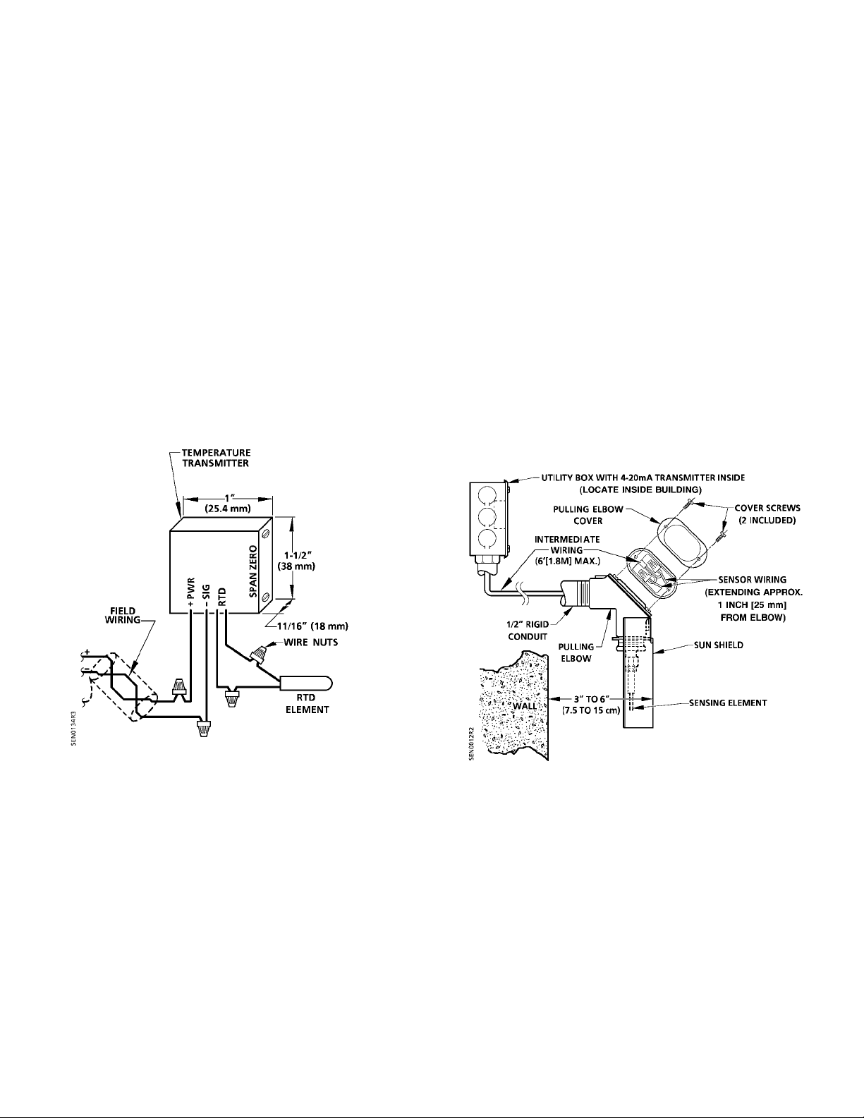
Figure 2. Analog Temperature Transmitter Wiring
Connections for 100 ohm RTD Sensors (Option A).
NOTE: Some Siemens Building Technologies
controllers may require a shield termination.
Option B Installation
NOTE: If replacing an existing sensor, disconnect the
positive (+) 26V supply lead of the field wiring
from the controller termination board or block.
1. Use an existing opening or drill an opening
through the outside wall for 1/2-inch (13 mm)
rigid conduit. The sensor must be located three
to six inches (7.5 to 15 cm) from the wall.
Page 2 of 3 Siemens Building Technologies, Inc.
Figure 3. Outside Air Sensor, Option B Installation.
8. Replace the pulling elbow cover and gasket.
Ensure that the gasket seals the pulling elbow.
9. Connect the intermediate wiring from the
sensing element to the appropriate transmitter
wires. See Figure 4 and Table 1.
10. Connect the field wiring from the controller to the
transmitter. The positive (+) 26V supply lead
goes to the PWR wire of the transmitter and
negative signal lead goes to the SIG wire. See
Figure 4 and Table 1.
Page 3
Document No. 538-495
Installation Instructions
March 17, 2005
Instructions, Continued
11. Remove the protective cover from the doublesided tape on the transmitter, and mount the unit
onto the utility box cover. Install the cover onto
the utility box.
12. Connect the field wiring at the controller. See
Figure 4 and Table 1.
The installation is now complete.
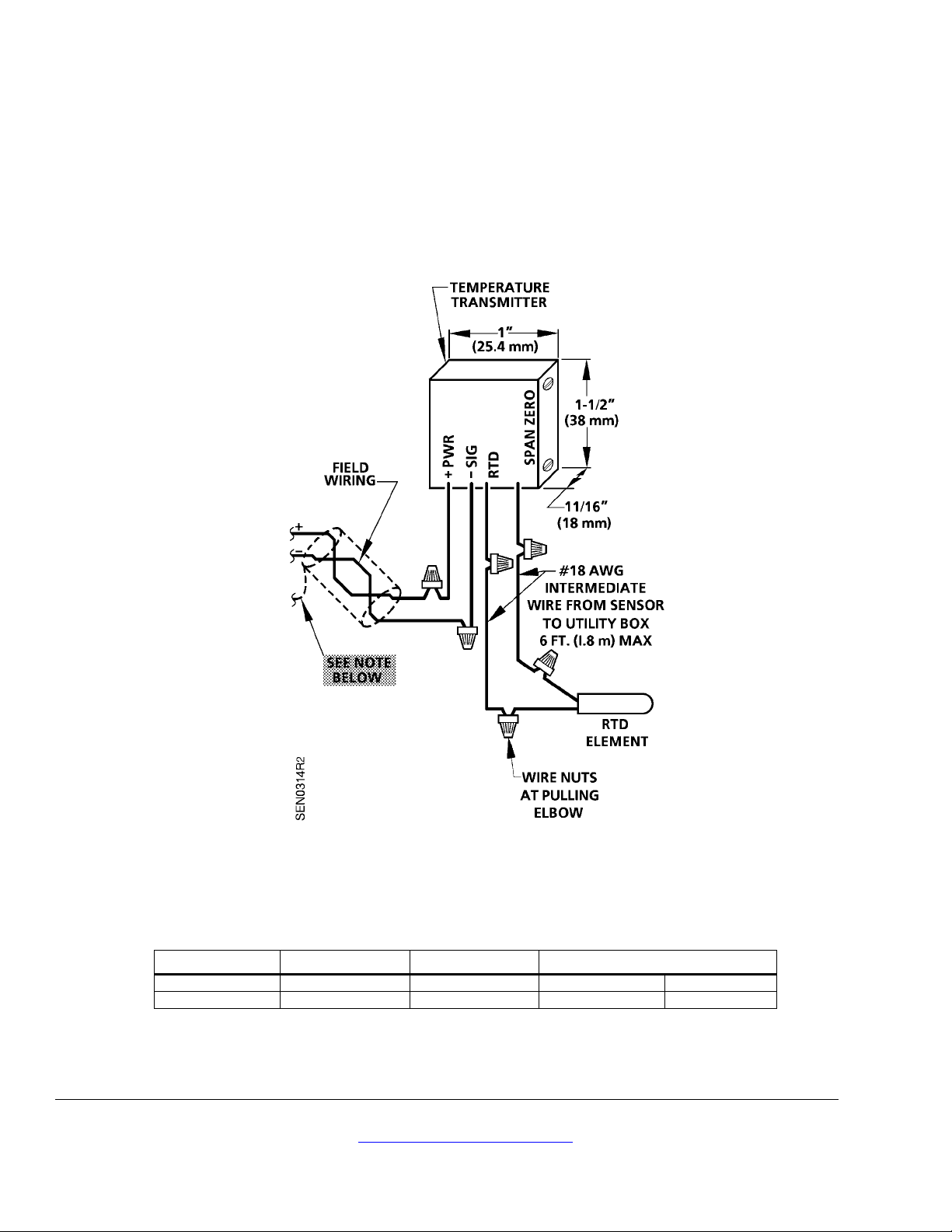
Figure 4. Analog Temperature Transmitter Wiring Connections for 4 to 20 mA Sensors (Option B).
NOTE: 1. Some Siemens Building Technologies controllers may require a shield termination.
2. For individual panel wiring details, see the appropriate hardware manual.
Table 1. Transmitter Lead Wire Color Codes.
Terminal PWR SIG RTD
Option 1 Red Brown Black Orange
Option 2 Red Black White White
NOTE: Wire colors vary by transmitter supplier.
Information in this publication is based on current specifications. The company reserves the right to make changes in specifications and models as
design improvements are introduced. Other product or company names mentioned herein may be the trademarks of their respective owners.
© 2005 Siemens Building Technologies, Inc.
Siemens Building Technologies, Inc.
1000 Deerfield Parkway
Buffalo Grove, IL 60089-4513
U.S.A.
Your feedback is important to us. If you have
comments about this document, please send them
to [email protected]
Document No. 538-495
Country of Origin: US
Page 3 of 3
 Loading...