

Page 1
Installation Instructions
Duct Averaging Sensors
20°F to 120°F
(-7°C to 49°C)
XX
Insertion Length in Feet (m)
8
8 (2)
16
16 (5)
24
24 (7)
CAUTION:
Equipment damage may
procedure as specified.
Document No. 129-512
October 12, 2009
Long Bendable Probe, 4 to 20 mA
Product Description
The temperature transmitter equipped Duct
Averaging Sensor assembly senses the average air
temperature in ductwork where mixing baffles are not
provided or where stratification occurs. Each sensor
assembly mounts on sheet metal ducts.
Contents
• Long, bendable, platinum RTD averaging
element
• 4 to 20 mA transmitter
• Electrical box for wiring connections
Product Numbers
Product
Number
533-380-XX
Warning/Caution Notations
Sensing
Element
100 Ω Pt (385α)
Range
Expected Installation Time
2.4 hours
Recommended Bulb Configur at ion
Figures 1 and 2 show the sensing element
arrangements. They provide the fastest response
when the element is exposed to cold temperatures.
Figure 1 shows the most practical mounting
arrangement; it does not require inside access to the
duct. The other sensing element arrangements
require inside access to the duct.
Mounting Hardware
Required for limited access duct
mounting option (Figure 1):
• Two mounting flanges (P/N 808-412).
• 16 No. 10 × 1-inch sheet metal screws.
• Tin snips.
• Pre-cut and drilled 8 × 4-inch (200 × 100 mm)
piece of sheet metal.
• Support rod of 3/8-inch OD copper or suitable
equivalent, long enough to fit diagonally
across the duct.
occur if you do not follow a
Required Tools
• Wire cutters
• Small, 1/8-inc h wide flat-blade screwdriver
• Medium flat-blade screwdriver
• Four No. 10 × 1-inch sheet metal screws
• Electric drill
• 1/2-inch (13 mm) and 7/8-inch (22 mm) drill
bits
• No. 27 drill bit for screw holes
• Tin snips
• Wire ties suitable for service in the ductwork
Item Number 129-512, Rev. AA Page 1 of 4
Required for walk-in duct mounting
option (Figure 2):
• Perforated steel hanger strap long enough to
traverse the duct at least twice.
• Wire ties suitable for service in the ductwork.
• Four No. 10 × 1-inch sheet metal screws.
Prerequisites
• The signal wiring must be pulled to the
installation site and enclosed in 3/8-inch
(9.5 mm) flexible conduit.
• For the limited access duct option, mount one
P/N 808-412 mounting flange and the sensor
on the 8 × 4-inch sheet metal plate.
Page 2
Document No. 129-512
CAUTION:
CAUTION:
Installation Instructions
October 12, 2009
Instructions for Limited Access
Duct Mounting Option
The duct sensing element is used to
detect temperature stratification in the
duct. For proper operation, be sure to
mount the sensing element at an angle,
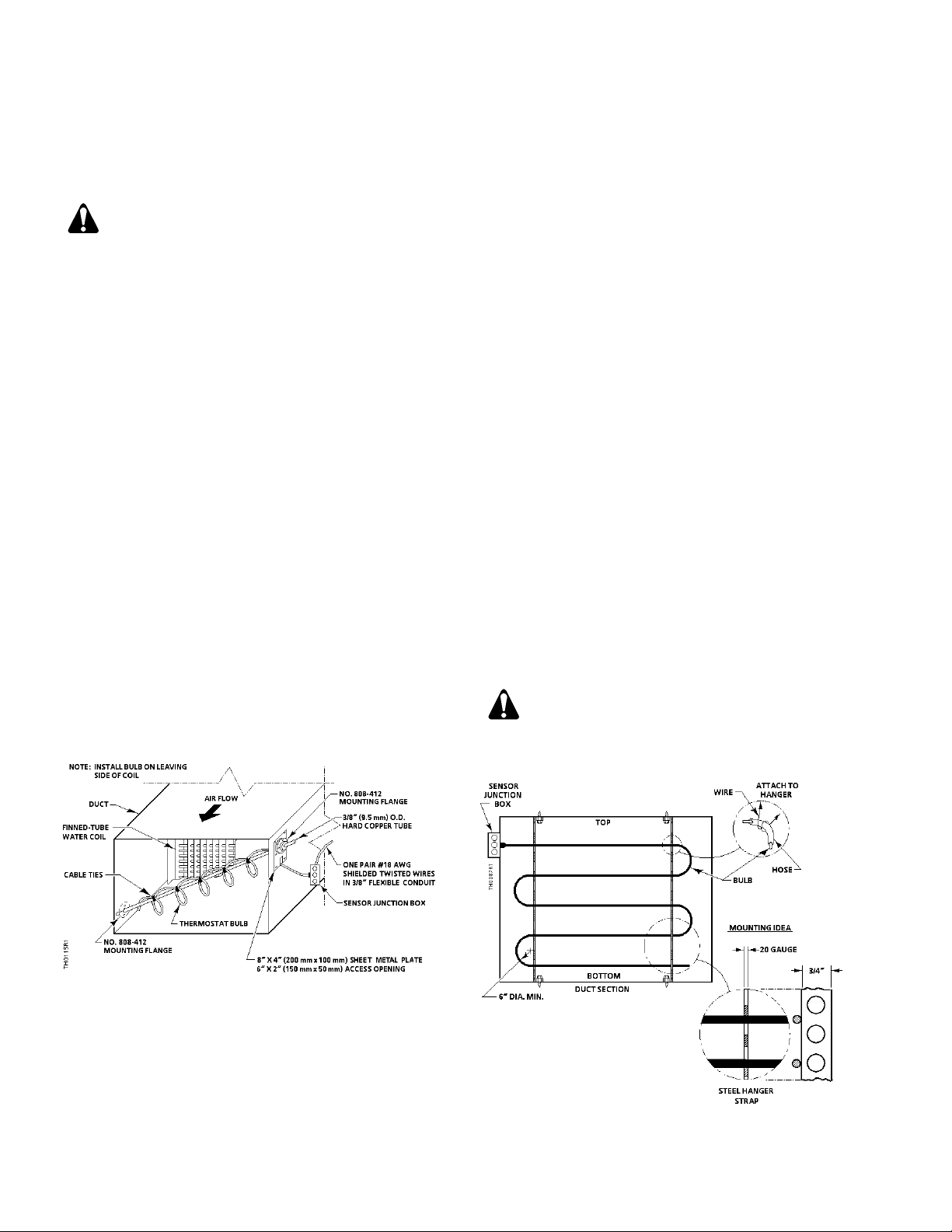
as shown in Figure 1.
When uncoiling the sensing element, do
NOT severely bend or kink the element.
The diameter of any bend should be no
less than six inches (152 mm).
1. Position one P/N 808-412 mounting flange on
the opposite side of the duct (near the bottom)
from where the 8 × 4-inch (200 mm × 100 mm)
mounting plate is to be mounted. See Figure 1.
Mark the four screw holes and the 1/2-inch
(13 mm) center hole of the mounting flange.
2. Drill the screw holes with the No. 27 drill bit.
3. Drill the center hole using a 1/2-inch (13 mm)
drill bit.
4. Mount the mounting flange on the duct.
7. Insert the tubing and attached sensing element
through the access hole and into the mounting
flange on the opposite side. Insert the attached
sensing element through the hole located on the
mounting plate.
8. Fasten the sheet metal plate to the duct. Tighten
the securing screws on each of the mounting
flanges.
NOTE: If leakage occurs around the sheet
metal plate, use caulking, glue or liquid
gasket to seal the leak.
9. Attach the junction box and conduit; pull wires
and terminate (see Figure 3). Replace cover.
The installation is now complete.
NOTE: Inserting the duct sensing element into
a round duct requires modification of
these instructions.
Instructions for Large Wal k-in
Ducts Mounting Option
NOTE: The duct sensing element should be
mounted in a horizontal, serpentine manner
as shown in Figures 2.
5. Cut a vertical access hole 6 inches high ×
Figure 1. Limited Access Duct Mounting Option.
6. Cut a length of 3/8-inch OD hard copper tubing to
fit diagonally across the duct. Insert the tube
through the mounting flange on the 8 × 4-inch
(200 mm × 100 mm) mounting plate. Stretch out
the sensing element and fasten it to the copper
tube using the cable ties.
Page 2 of 4 Siemens Industry, Inc.
2 inches wide (150 × 50 mm) (near the top of the
duct) on the side opposite of the previously
mounted mounting flange. See Figure 1. Mark
and drill mounting screw holes for the sheet
metal plate.
1. Position and mark the screws holes for the two
or more steel straps, as shown in Figure 2
The wide part of the hanger strap must be
parallel to the airflow in the duct to ensure
minimum airflow resistance.
Figure 2 Large Walk-In Duct Mounting Option.
Page 3
Document No. 129-512
CAUTION:
Option 1
Red
Brown
Black
Orange
Option 2
Red
Black
White
White
Installation Instructions
October 12, 2009
2. Use the No. 27 drill bit to drill holes for the
hanger straps.
3. Mount the two perforated steel strap hangers
inside the duct.
4. Position the sensor junction box on the duct and
mark the four mounting holes and center hole.
Use a No. 27 drill bit to drill the mounting holes
and a 7/8-inch (22 mm) drill bit to drill the center
hole.
5. With the sensing element still coiled, thread the
sensing element through the center hole using a
rotary movement.
6. When the sensing element has been completely
inserted into the duct, mount the sensor junction
box on the duct.
7. Carefully uncoil the sensing element, avoiding
sharp bends or kinks.
When uncoiling the sensing element, do
NOT severely bend or kink the element.
The diameter of any bend should be no
less than six inches (152 mm).
8. Attach the junction box and conduit; pull wires
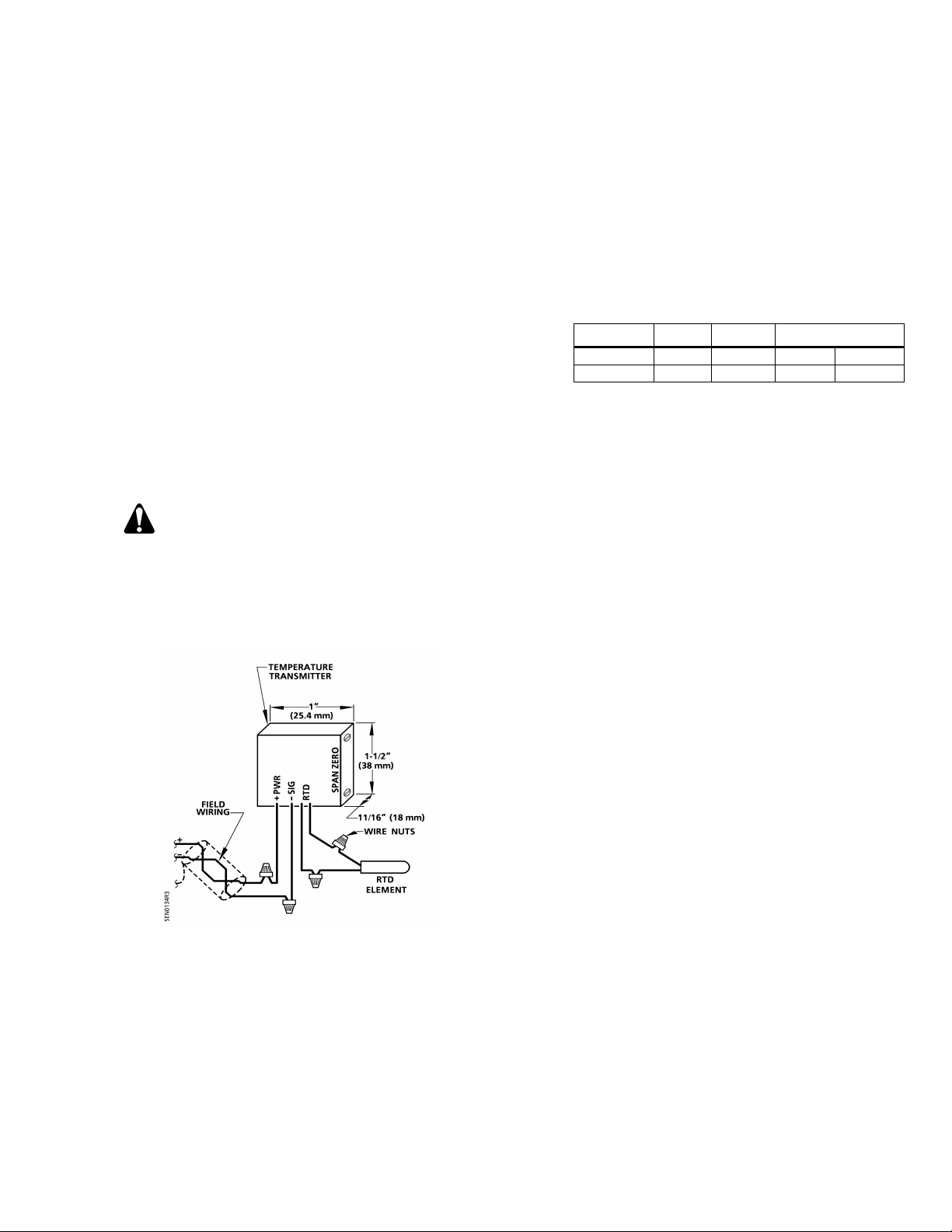
and terminate (see Figure 3).
9. Strip the field wires with wire cutters and connect
the positive (+) 26V lead wire to the transmitter's
PWR wire. Connect the signal lead wire to the
transmitter's SIG wire. See Figure 3 and Table 1.
10. Replace the 2-inch × 4-inch electrical box cover
on the transmitter assembly box.
The installation is now complete.
Table 1 Transmitter Lead Wire Color Codes.
Terminal PWR SIG RTD
NOTE: 1. Wire colors vary by transmitter
supplier.
2. The 4 to 20 mA transmitter located in
the sensor junction box must be within
an ambient temperature of 32°F to
122°F (0°C to 50°C) and 5 to 99% rh.
If local conditions exceed these
requirements, relocate the transmitter
to an area that meets the ambient
requirements.
3. The transmitter can be connected to
the RTD element over a distance of up
to 25 feet (7.5 m) using a shielded
twisted pair of 16 AWG wires which
results in a +1°F (0.56°C) error.
Figure 3. Analog Temperature Transmitter
Wiring Connections.
NOTE: For individual panel wiring details, see the
appropriate hardware manual.
Siemens Industry, Inc. Page 3 of 4
Page 4
Document No. 129-512
Siemens Indus try, Inc.
+ 1 847-215-1000
Installation Instructions
October 12, 2009
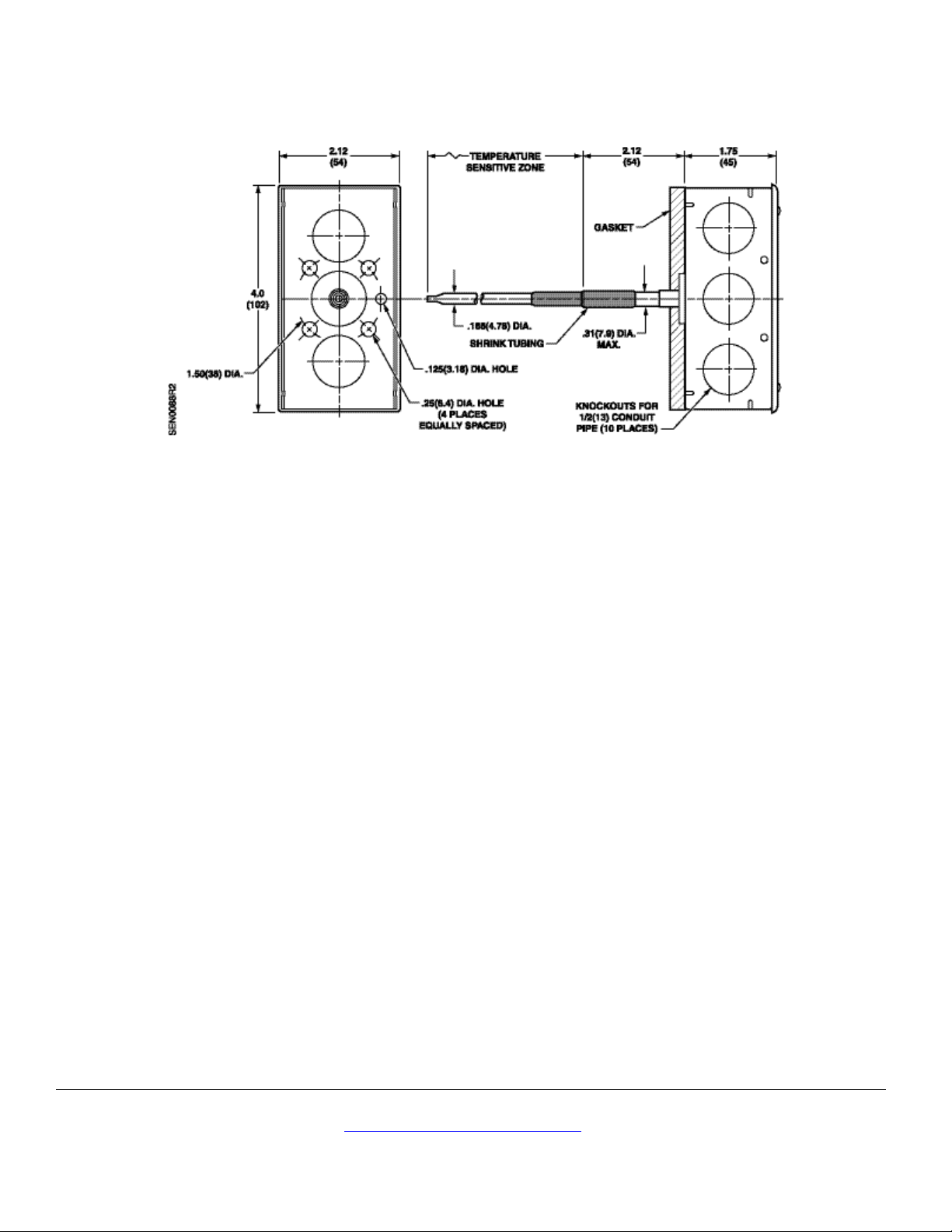
Figure 4 Mounting Hole Locations and Dimensions of Sensor Junction Box.
Information in this publication is based on current specifications. The company reserves the right to make changes in specifications and models as
design improvements are introduced. Products or company names mentioned herein may be the trademarks of their respective owners.
© 2009 Siemens Industry, Inc.
Building Technologies Division
1000 Deerfield Parkway
Buffalo Grove, IL 60089
Your feedback is important to us. If you have
comments about this document, please send them to
Document No.129-512
Printed in the USA
Page 4 of 4
 Loading...