

Page 1
3EQ Composite Housed
Surge Arresters
Saving Money and Space, Gaining Reliability
Power Transmission and Distribution
1
Page 2
A perfect Combination of
Cost-Savings, Safety and Reliability
3EQ Surge Arresters:
Your Reliable, Sturdy and Economic Choice
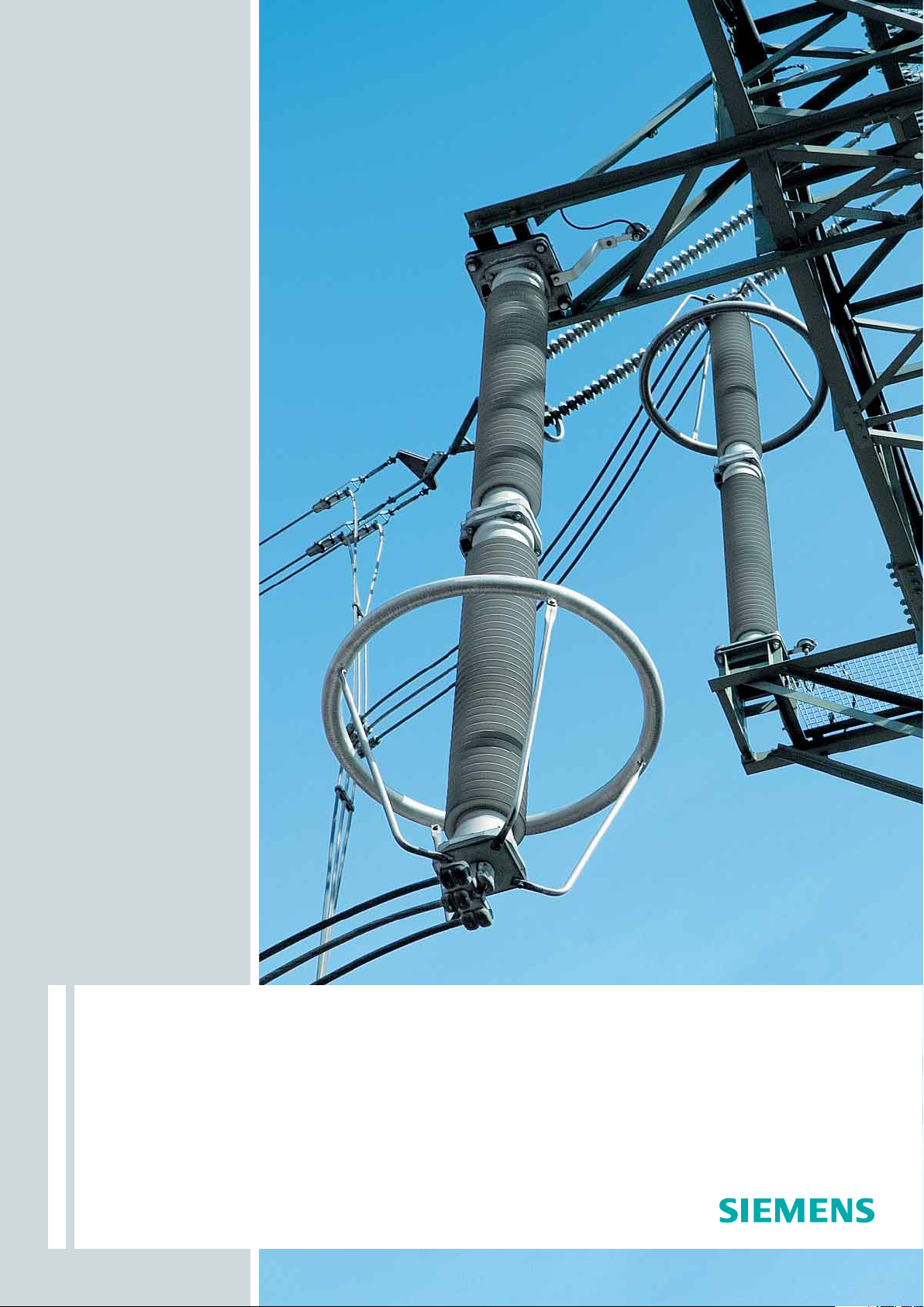
3EQ surge arresters are virtually indestructible. While their tube
design provides the highest possible mechanical strength and
enables them to support high bending moments, the silicone
rubber insulation is ideal for outdoor applications in severe
environmental conditions. No matter how tough the environmental or operating conditions may be, our 3EQ arresters
assures a 100 % reliable pressure relief performance, they provide the ultimate in protection. They are break-proof and retain
at least 75 % of their mechanical strength even after pressure
relief. They provide the greatest stability, even in earthquakes.
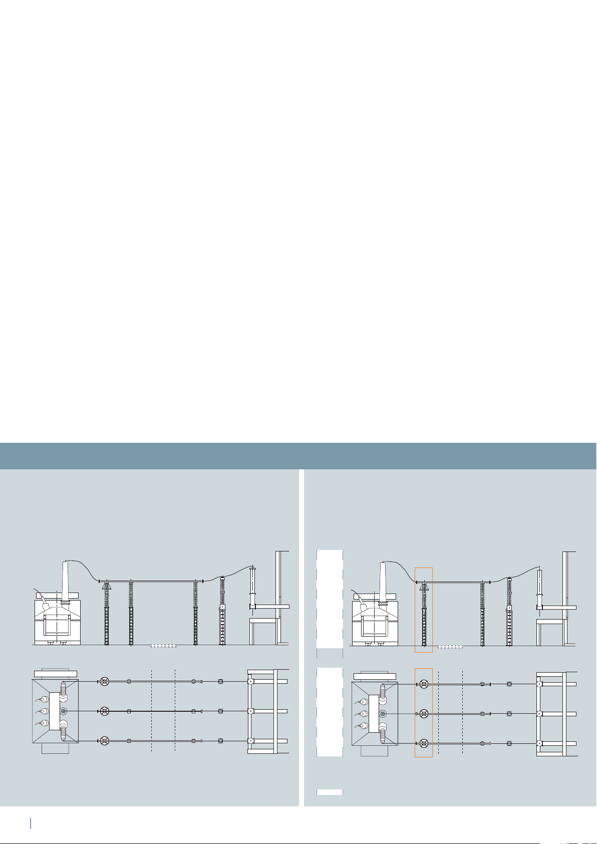
Reduced Space Requirements
Their advantages are more than convincing, a perfect combination of cost-savings and safety for your substations. The
combination of silicone rubber and fiber-glass-reinforced tube
imparts enormous load carrying capacity to the structure. Thus,
our 3EQ surge arresters are the perfect choice to replace existing post insulators in your substations up to voltages of 800 kV.
Where space is most essential, 3EQ surge arresters can even be
mounted over the transformer to support connectors without
any danger to neighboring equipment. This assures maximum
stability, even if the arresters should “blow out” after overloading. Pressure relief is absolutely reliable – there is no danger
to equipments in the direct vicinity. Due to their unique tube
design, no parts will be expelled, and the emerging arc will
burn between the ends of the pressure relief device.
Longevity and Reliability
The 3EQ’s Silicone Rubber housings provide the best possible
long-life-performance for high-voltage surge arresters. They
make use of all the advantages of bonding vulcanized-on
silicone rubber sheds to a fiberglass-reinforced plastic tube,
providing enhanced safety and meeting every requirement.
And, with their silicone rubber housings, the arresters enjoy
all-round protection. The silicone rubber shield provides a reliable defense against snow, sandstorms, ozone, high-level UV
radiation, sea salt, soot and acid rain in industrial regions. Only
genuine silicone rubber is capable of maintaining its hydrophobic properties throughout its entire service life – and is resistant
to UV radiation. The silicone rubber of the 3EQ surge arresters
reliably prevents the formation of films of water or dirt. Surface
currents resulting from conductive layers of accumulated dirt
are eliminated.
The cost-saving solution for your substation
You require fewer post insulators for your installation,
thereby saving you both money and space.
Transformer
Surge
Support Support
arreser
Street
Voltage
transformer
GIS bushing
Saved installment space
Transformer 3EQ as support
Street
Support
Voltage
transformer
GIS bushing
Diagram of substation prior to 3EQ modification
2
Diagram of substation with integrated 3EQ modification
Page 3
A lot more speaks for the efficiency of 3EQ
Their dramatically reduced weight means savings right
from the start – in transportation, in support structures
and in installation. The weight reduction in our polymeric
arresters compared with porcelain types is amazing.
In fact, highvoltage arresters with composite housings are
about 50 % lighter than their porcelain counterparts. This
makes all the difference: Initially in terms of transportation
costs. Then there is installation and commissioning –
involving reduced labor costs, less complex support structures and simple hoisting gear. The cranes required can be
significantly smaller – and the cost using them correspondingly lower. And there‘s another way in which they save
costs – polymeric arresters don‘t need cleaning. By virtue
of its hydrophobic properties, everything is so much simpler with silicone rubber throughout its entire service life.
They provide numerous advantages – a gain for everyone,
thanks to Siemens know-how for innovations and unsurpassed quality of manufacture.
All 3EQ advantages at a glance are
Maximized service life
100 % break-proof – reliable overload performance,
no hazardous splinters even under maximum pressure:
these arresters can even be installed in close proximity
to costly system components
Safe from damage – unbreakable during transportation,
installation, storms, earthquakes and immune to vandalism
Outstanding stability in earthquake and storm:
these arresters can be used to replace post insulators
Use of silicone rubber – hydrophobic, resistant to pollution
and to UV radiation
Extremely rugged – reliable in any climate and
polluted environment
Substantially reduced weight – ease of installation with
simple lifting gear
Complete and wide product range, special versions to order
Cost-effective in all respects – maximum availability –
for many special application and installation needs
Reduce the required space even more
It‘s no problem to install our 3EQ surge arrester on top
of the transformer! There is no danger to equipment,
even in the direct vicinity.
3EQ as support Voltage
Transformer
Street
transformer
GIS bushing
Sealing
system
Directional pressure
relief device
Nitrogen
FRP rods
Metal oxide
blocks
Glass fibre
reinforced tube
Silicone
rubber housing
Clearance between equipment according to technical standards
3
Page 4
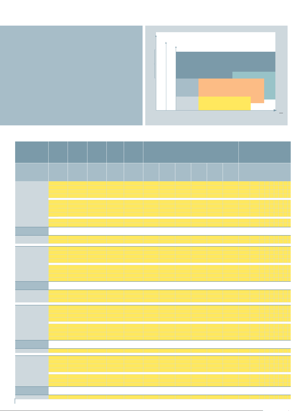
Diagram 1
Choose the Appropriate Arrester
In just four steps you can choose the right surge arrester:
1. First step choose the type 3EQ1, 3EQ4 or 3EQ3
from diagram 1.
2. Second step verify the maximum technical data
with table 1.
3. Third step choose the surge arrester with table 2.
4. Fourth step select the suitable installation and
grounding and complete the order number with table 3.
Table 2
Highest voltage
for equipment
U
m
[kV]
72.5 325 54 43 2 500 133 143 160 110 114 120 3EQ1 054 – 1 P B 2 1 –
Neutral-ground arresters
Um [kV]
72.5
123 450 96 77 2 500 237 254 285 196 204 214 3EQ1 096 – 1 P J 2 1 –
Neutral-ground arresters
Um [kV]
123
Resonant earthed
145 550 111 89 2 500 274 294 329 227 235 247 3EQ1 111 – 1 P J 2 1 –
Neutral-ground arresters
Um [kV]
145
170 650 138 110 2 500 340 366 410 282 293 307 3EQ1 138 – 1 P P 2 1 –
Neutral-ground arresters
Um [kV]
170
1) According to IEC 60099-4 these values are measured on individual housing units
4
Standard
lightning
impulse
withstand
voltage
Rated
voltage
Continuous
operating
voltage
Line
discharge
class
Long
duration
current
2 ms
BIL min
[kV]
[kV]
U
r
U
c
[kV] LD-Cl [A]
325 54 43 3 850 122 130 144 104 106 111 3EQ1 054 – 2 P B 3 1 –
325 60 48 2 500 148 159 178 122 127 134 3EQ1 055 – 1 P B 2 1 –
325 60 48 2 850 130 138 153 110 113 119 3EQ1 056 – 2 P B 2 1 –
325 60 48 3 850 135 144 160 115 118 124 3EQ1 060 – 2 P B 3 1 –
325 66 53 2 500 163 175 196 135 140 147 3EQ1 066 – 1 P B 2 1 –
325 66 53 2 850 143 152 168 121 124 131 3EQ1 066 – 2 P B 2 1 –
325 66 53 3 850 149 158 176 127 130 136 3EQ1 066 – 2 P B 3 1 –
325 72 58 2 500 177 191 214 147 153 160 3EQ1 072 – 1 P B 2 1 –
325 72 58 3 850 162 173 192 138 142 149 3EQ1 072 – 2 P B 3 1 –
325
325
30 24 2 500 74.0 79.5 89.0 61.2 63.6 66.8 3EQ1 030 – 1 S B 2 1 –
30 24 3 850 67.7 72.0 79.9 57.6 59.0 61.9 3EQ1 030 – 2 S B 3 1 –
450 96 77 2 850 208 221 245 177 181 190 3EQ1 096 – 2 P J 2 1 –
450 96 77 3 850 217 230 256 184 189 198 3EQ1 096 – 2 P J 3 1 –
450 102 82 2 500 251 270 303 208 216 227 3EQ1 102 – 1 P J 2 1 –
450 102 82 3 850 230 245 272 196 201 211 3EQ1 102 – 2 P J 3 1 –
450 108 86 2 500 266 286 321 220 229 240 3EQ1 108 – 1 P J 2 1 –
450 108 86 3 850 244 259 288 207 213 223 3EQ1 108 – 2 P P 3 1 –
450 111 89 3 850 250 266 296 213 218 229 3EQ1 111 – 2 P P 3 1 –
450 51 41 2 500 126 135 151 104 108 114 3EQ1 051 – 1 S B 2 1 –
550
550
90 72 2 850 195 207 230 166 170 178 3EQ1 090 – 2 S E 2 1 –
96 77 2 850 208 221 245 177 181 190 3EQ1 096 – 2 S J 2 1 –
550 111 89 2 850 240 255 283 204 209 220 3EQ1 111 – 2 P J 2 1 –
550 120 96 2 500 296 318 356 245 254 267 3EQ1 120 – 1 P P 2 1 –
550 120 96 3 850 271 288 320 230 236 248 3EQ1 120 – 2 P P 3 1 –
550 126 101 3 850 284 302 336 242 248 260 3EQ1 126 – 2 P P 3 1 –
550 132 106 3 850 298 317 352 253 260 272 3EQ1 132 – 2 P P 3 1 –
550 144 115 2 850 311 331 368 265 272 285 3EQ1 144 – 2 P P 2 1 –
550 144 115 3 850 325 346 384 276 283 297 3EQ1 144 – 2 P P 3 1 –
550
60 48 2 500 148 159 178 122 127 134 3EQ1 060 – 1 S B 2 1 –
650 138 110 2 850 298 317 352 254 260 273 3EQ1 138 – 2 P P 2 1 –
650 138 110 3 850 311 331 368 265 272 285 3EQ1 138 – 2 P P 3 1 –
650 144 115 2 500 355 382 427 294 305 321 3EQ1 144 – 1 P P 2 1 –
650 144 115 3 850 325 346 384 276 283 297 3EQ1 144 – 2 P P 3 1 –
650 144 115 3 850 325 346 384 276 283 297 3EQ1 144 – 2 P P 3 1 –
650 150 120 3 850 338 360 400 288 295 310 3EQ1 150 – 2 P P 3 1 –
650 69 55 2 500 170 183 205 141 146 154 3EQ1 069 – 1 S B 2 1 –
LD-class
Long duration current impulse Max. value/A
Bending Moment/kNm
72
42
Special
application
38
Special
21
application
6
Special
application
12 36 52 72 123 145 170 245 300 362 420 550
3 and 4
2 and 3
5000
4125
5
2750
2100
1600
1200
850
2
500
Maximum values of the residual voltages at
discharge currents of the following impulses
8/20 µs
5 kA
[kV]
8/20 µs
10 kA
[kV]
8/20 µs
20 kA
[kV]
30/60 µs
0.5 kA
[kV]
30/60 µs
1 kA
[kV]
30/60 µs
2 kA
[kV]
3EQ1
3EQ4
3EQ3
800
Arrester type
U
m
kV
Page 5

Table 1
Diagram 2/Diagram 3:
Power-frequency voltage versus time characteristic
Maximum values 3EQ1 3EQ4 3EQ3
Nominal system voltage U
Highest voltage
for equipment U
m
Maximum rated voltage U
Maximum nominal
discharge current I
Maximum line discharge
class
Maximum energy
absorption capability
Maximum long duration
n
current impuls
Rated short circuit current
Maximum permissible
service load
kV
n
kV
kV
r
kA
345 500 765
362 550 800
288 468 612
10 20 20
355
kJ/kVr 8 18 27
A 850 2100 5500
kA
50 65 80
kNm 6 38 72
To find the right arrester just follow the color codes
3EQ1 3EQ4 3EQ3
Height
[H]
Number of
units
Housing insulation Creepage
p. u. Ur [kV]
p. u. Ur [kV]
distance
1.4
1.3
1.2
1.1
1.0
0.9
0.8
0.7
0.1 1 10 100 1000
1.4
1.3
1.2
1.1
1.0
0.9
0.8
0.7
0.1 1 10 100 1000
Top load
dynamic
Grading ring
diameter
Weight TOV Diagram Figure
Preheating to 40 °C
Preheating to 60 ° C and
stressing with rated energy
t [s]
Preheating to 40 ° C
Preheating to 60° C and
stressing with rated energy
Temporary Over Voltage
(TOV)
t [s]
[D]
Lightning impulse
[mm]
withstand voltage
1.2/50 µs
1)
[kV]
Power frequency withstand
voltage 1 min., wet
1)
[kV] [mm] [N] [mm] [kg]
4 xxx 885 1 348 162 2075 6800 – 25 2 11
4 xxx 885 1 348 162 2075 6800 – 27 2 11
4 xxx 885 1 348 162 2075 6800 – 25 2 11
4 xxx 885 1 348 162 2075 6800 – 27 3 11
4 xxx 885 1 348 162 2075 6800 – 27 2 11
4 xxx 885 1 348 162 2075 6800 – 26 2 11
4 xxx 885 1 348 162 2075 6800 – 28 3 11
4 xxx 885 1 348 162 2075 6800 – 28 2 11
4 xxx 885 1 348 162 2075 6800 – 26 2 11
4 xxx 885 1 348 162 2075 6800 – 29 2 11
4 xxx 885 1 348 162 2075 6800
4 xxx 885 1 348 162 2075 6800
–
–
23 2 11
24 2 11
4 xxx 1235 1 551 257 3390 4900 – 32 2 11
4 xxx 1235 1 551 257 3390 4900 – 35 3 11
4 xxx 1235 1 551 257 3390 4900 – 36 2 11
4 xxx 1235 1 551 257 3390 4900 – 33 2 11
4 xxx 1235 1 551 257 3390 4900 – 37 2 11
4 xxx 1235 1 551 257 3390 4900 – 33 2 11
4 xxx 1235 1 551 257 3390 4900 – 38 2 11
4 xxx 1235 1 551 257 3390 4900 – 38 2 11
4 xxx 885 1 348 162 2075 6800 – 25 2 11
4 xxx 1035 1 435 203 2635 5800
4 xxx 1235 1 551 257 3390 4900
–
–
33 3 11
33 3 11
4 xxx 1235 1 551 257 3390 4900 – 68 2 11
4 xxx 1235 1 551 257 3390 4900 – 71 3 11
4 xxx 1485 1 696 324 4330 4000 – 72 2 11
4 xxx 1485 1 696 324 4330 4000 – 76 2 11
4 xxx 1485 1 696 324 4330 4000 – 77 2 11
4 xxx 1485 1 696 324 4330 4000 – 78 2 11
4 xxx 1485 1 696 324 4330 4000 – 79 3 11
4 xxx 1485 1 696 324 4330 4000 – 79 2 11
4 xxx 1050 1 484 334 2490 5700
–
26 2 11
4 xxx 1485 1 696 324 4330 4000 – 39 2 11
4 xxx 1485 1 696 324 4330 4000 – 44 3 11
4 xxx 1485 1 696 324 4330 4000 – 45 2 11
4 xxx 1485 1 696 324 4330 4000 – 39 2 11
4 xxx 1485 1 696 324 4330 4000 – 45 2 11
4 xxx 1485 1 696 324 4330 4000 – 45 2 11
4 xxx 1485 1 696 324 4330 4000 – 46 2 11
4 xxx 885 1 348 162 2075 6800 – 26 2 11
5
Page 6

Highest voltage
for equipment
Standard
lightning
impulse
withstand
voltage
Rated
voltage
Continuous
operating
voltage
Line
discharge
class
Long
duration
current 2 ms
Maximum values of the residual voltages at
discharge currents of the following impulses
Arrester type
[kV]
245 850 192 154 2 500 473 509 570 392 407 427 3EQ1 192 – 1 P J 2 2 –
Neutral-ground arresters
Um [kV]
245 850 102 82 2 500 251 270 303 208 216 227 3EQ1 102 – 1 S J 2 1 –
300 850 228 182 2 500 562 604 677 465 483 508 3EQ1 228 – 1 P P 2 2 –
Neutral-ground arresters
Um [kV]
300 850 120 96 2 500 296 318 356 245 254 267 3EQ1 120 – 1 S J 2 1 –
362
Neutral-ground arresters
U
m
362 950 147 117 3 850 332 353 392 282 289 303 3EQ1 147 – 2 S P 3 1 –
420 1175 336 268 3 850 758 806 895 645 661 694 3EQ4 336 – 2 P R 3 2 –
Neutral-ground arresters
Um [kV]
420 1175
550 1300 396 316 5 1600 865 911 993 747 774 802 3EQ4 396 – 4 P V 5 2 –
800 1800 570 456 5 2100 1208 1271 1373 1068 1093 1131 3EQ3 570 – 5 P S 5 3 –
6
U
[kV]
m
BIL min
[kV]
U
[kV]
r
U
c
[kV] LD-Cl [A]
8/20 µs
5 kA
[kV]
8/20 µs
10 kA
[kV]
8/20 µs
20 kA
[kV]
30/60 µs
0.5 kA
[kV]
30/60 µs
1 kA
[kV]
30/60 µs
2 kA
[kV]
850 192 154 2 850 415 442 490 353 362 380 3EQ1 192 – 2 P J 2 2 –
850 192 154 3 850 433 461 511 369 378 396 3EQ1 192 – 2 P J 3 2 –
850 192 154 3 850 433 461 511 369 378 396 3EQ4 192 – 2 P R 3 1 –
850 192 154 4 1200 424 451 496 366 375 393 3EQ4 192 – 3 P R 4 1 –
850 198 158 2 500 488 525 588 404 420 441 3EQ1 198 – 1 P J 2 2 –
850 198 158 2 850 428 455 505 364 373 392 3EQ1 198 – 2 P J 2 2 –
850 198 158 3 850 447 475 527 380 390 409 3EQ1 198 – 2 P J 3 2 –
850 198 158 3 850 447 475 527 380 390 409 3EQ4 198 – 2 P R 3 1 –
850 198 158 4 1200 437 465 512 377 386 405 3EQ4 198 – 3 P R 4 1 –
850 228 182 3 850 514 547 607 438 449 471 3EQ1 228 – 2 P J 3 2 –
850 228 182 3 850 514 547 607 438 449 471 3EQ4 228 – 2 P V 3 1 –
850 228 182 2 850 493 524 582 420 430 451 3EQ1 228 – 2 P P 2 2 –
850 228 182 3 850 514 547 607 438 449 471 3EQ1 228 – 2 P P 3 2 –
850 228 182 3 850 514 547 607 438 449 471 3EQ4 228 – 2 P V 3 1 –
850 228 182 4 1200 504 536 589 434 445 466 3EQ4 228 – 3 P V 4 1 –
950 240 192 2 500 592 636 712 490 509 534 3EQ1 240 – 1 P P 2 2 –
850 240 192 2 850 519 552 613 442 453 475 3EQ1 240 – 2 P P 2 2 –
850 240 192 3 850 541 576 639 461 472 495 3EQ1 240 – 2 P P 3 2 –
850 240 192 3 850 541 576 639 461 472 495 3EQ4 240 – 2 P V 3 1 –
850 240 192 4 1200 530 564 620 457 468 491 3EQ4 240 – 3 P V 4 1 –
950 276 220 3 850 623 662 735 530 543 570 3EQ4 276 – 2 P N 3 2 –
950 276 220 4 1200 610 649 713 526 538 564 3EQ4 276 – 3 P N 4 2 –
1050 288 230 3 850 650 691 767 553 567 594 3EQ4 288 – 2 P N 3 2 –
1050 288 230 4 1200 636 677 744 548 562 589 3EQ4 288 – 3 P N 4 2 –
1175 360 288 2 850 778 828 919 662 679 712 3EQ4 360 – 2 P N 2 2 –
1175 336 268 4 1200 742 790 869 640 656 687 3EQ4 336 – 3 P R 4 2 –
1175 336 268 5 1600 734 773 842 634 657 680 3EQ4 336 – 4 P R 5 2 –
1175 336 268 5 1600 734 773 842 634 657 680 3EQ3 336 – 4 P M 5 2 –
1300 360 288 3 850 812 864 959 691 708 743 3EQ4 360 – 2 P R 3 2 –
1300 360 288 4 1200 795 846 931 685 702 736 3EQ4 360 – 3 P R 4 2 –
1175 360 288 5 1600 787 828 903 679 704 729 3EQ4 360 – 4 P R 5 2 –
1175 360 288 5 1600 787 828 903 679 704 729 3EQ3 360 – 4 P N 5 2 –
168 134 3 850 379 403 448 323 331 347 3EQ1 168 – 2 S S 3 1 –
1300 396 316 5 2100 839 883 954 742 760 786 3EQ4 396 – 5 P V 5 2 –
1300 399 319 5 1600 872 918 1000 753 780 808 3EQ4 399 – 4 P V 5 2 –
1300 399 319 5 2100 845 890 961 747 765 792 3EQ4 399 – 5 P V 5 2 –
1425 420 336 5 1600 918 966 1053 792 821 850 3EQ4 420 – 4 P V 5 2 –
1425 420 336 5 2100 890 937 1011 787 806 834 3EQ4 420 – 5 P V 5 2 –
1425 420 336 5 2100 890 937 1011 787 806 834 3EQ3 420 – 5 P S 5 2 –
1550 444 355 5 1600 970 1021 1113 837 868 899 3EQ4 444 – 4 P V 5 2 –
1550 444 355 5 1600 970 1021 1113 837 868 899 3EQ3 444 – 4 P T 5 2 –
1425 444 355 5 2100 941 990 1069 832 852 881 3EQ4 444 – 5 P V 5 2 –
1425 444 355 5 2100 941 990 1069 832 852 881 3EQ3 444 – 5 P T 5 2 –
1950 588 470 5 2100 1246 1311 1416 1101 1128 1167 3EQ3 588 – 5 P T 5 3 –
1950 597 477 5 2100 1265 1331 1438 1118 1145 1185 3EQ3 597 – 5 P T 5 3 –
1950 612 489 5 2100 1297 1365 1474 1146 1174 1215 3EQ3 612 – 5 P U 5 3 –
1) According to IEC 60099-4 these values are measured on individual housing unit
Page 7

Height
[H]
Number of
units
Housing insulation Creepage
distance
Top load
dynamic
Grading ring
diameter
[D]
Weight
TOV
Diagram
Figure
[mm]
Lightning impulse
withstand
voltage 1.2/50 µs
[kV]
1)
Power frequency
withstand voltage
1 min., wet
1)
[kV] [mm] [N] [mm] [kg]
4 xxx 2470 2 1102 513 6780 2400 800 64 2 12
4 xxx 2470 2 1102 513 6780 2400 800 71 3 12
4 xxx 2470 2 1102 513 6780 2400 800 72 2 12
4 xxx 2060 1 806 375 6210 10200 800 109 2 41
4 xxx 2060 1 806 375 6210 10200 800 119 2 41
4 xxx 2470 2 1102 513 6780 2400 800 65 2 12
4 xxx 2470 2 1102 513 6780 2400 800 72 3 12
4 xxx 2470 2 1102 513 6780 2400 800 72 2 12
4 xxx 2060 1 806 375 6210 10200 800 110 2 41
4 xxx 2060 1 806 375 6210 10200 800 120 2 41
4 xxx 2470 2 1102 513 6780 2400 800 76 2 12
4 xxx 2460 1 1035 482 7715 8500 800 118 2 41
4 xxx 1235 1 551 257 3390 4900 – 33 2 12
4 xxx 2970 2 1392 1008 8660 2000 1000 77 2 12
4 xxx 2970 2 1392 1008 8660 2000 1000 85 3 12
4 xxx 2970 2 1392 1008 8660 2000 1000 86 2 12
4 xxx 2460 1 1035 750 7715 8500 800 118 2 41
4 xxx 2460 1 1035 750 7715 8500 800 130 2 41
4 xxx 2970 2 1392 1008 8660 2000 1000 79 2 12
4 xxx 2970 2 1392 1008 8660 2000 1000 86 3 12
4 xxx 2970 2 1392 1008 8660 2000 1000 88 2 12
4 xxx 2460 1 1035 750 7715 8500 800 119 2 41
4 xxx 2460 1 1035 750 7715 8500 800 132 2 41
4 xxx 1235 1 551 399 3390 4900 0 34 2 11
4 xxx 3520 2 1624 1176 10170 6000 1200 175 2 42
4 xxx 3520 2 1624 1176 10170 6000 1200 189 2 42
4 xxx 3520 2 1624 1176 10170 6000 1200 176 2 42
4 xxx 3520 2 1624 1176 10170 6000 1200 191 2 42
4 xxx 3520 2 1624 1176 10170 6000 1200 183 3 42
4 xxx 1485 1 696 504 4330 4000 0 45 2 11
4 xxx 4120 2 1612 1168 12420 5100 1500 191 2 42
4 xxx 4120 2 1612 1168 12420 5100 1500 210 2 42
4 xxx 4120 2 1612 1168 12420 5100 1500 227 2 42
4 xxx 3600 2 1682 1218 10540 11700 1200 279 2 32
4 xxx 4120 2 1612 1168 12420 5100 1500 194 2 42
4 xxx 4120 2 1612 1168 12420 5100 1500 214 2 42
4 xxx 4120 2 1612 1168 12420 5100 1500 234 2 42
4 xxx 3800 2 1798 1302 11300 11100 1200 292 2 32
4 xxx 1635 1 783 567 4895 3700 0 50 2 11
4 xxx 4920 2 2071 1499 15430 4300 1800 251 2 42
4 xxx 4920 2 2071 1499 15430 4300 1800 311 2 42
4 xxx 4920 2 2071 1499 15430 4300 1800 251 2 42
4 xxx 4920 2 2071 1499 15430 4300 1800 311 2 42
4 xxx 4920 2 2071 1499 15430 4300 1800 256 2 42
4 xxx 4920 2 2071 1499 15430 4300 1800 319 2 42
4 xxx 4600 2 1891 1369 14300 9100 1800 386 2 32
4 xxx 4920 2 2071 1499 15430 4300 1800 263 2 42
4 xxx 4800 2 2007 1453 15060 8800 1800 333 2 32
4 xxx 4920 2 2071 1499 15430 4300 1800 327 2 42
4 xxx 4800 2 2007 1453 15060 8800 1800 397 2 32
4 xxx 6900 3 2836 2054 21450 6100 2200 557 2 33
4 xxx 7200 3 3010 2180 22590 5800 2200 571 2 33
4 xxx 7200 3 3010 2180 22590 5800 2200 577 2 33
4 xxx 7500 3 3184 2306 23700 5600 2650 592 2 33
7
Page 8

Housings
3EQ1
11
3EQ1
12
3EQ4
41
3EQ4
42
3EQ3
32
3EQ3
33
Figure
8
Page 9

Installation and Grounding 3EQ1
M12
30
200
260
200
260
298
60
100
50
25
24
3
30
(87)
(15)
50
ø14
1148
4 mounting holes 200 x 200 mm for insulated installation
380
310
M12
60
30
310
380
ø24
4 mounting holes 310 x 310 mm for insulated installation
80
44.5/50
44.5/50
M12
DIN flat terminal
100
44.5
28
24
3
30
(87)
(16)
44.5
ø14
1148
NEMA flat terminal
ø30
80
Additional cable clamp for flat terminal Bolt terminal
80
9
Page 10

Control Devices for Surge Arresters
These control devices can be connected
to all shown surge arresters in this catalogue.
Arrester condition indicator
The arrester condition indicator (ACI)
shows the arrester status at a glance.
Its easy-to- understand “traffi c light”
visualisation is based on a 3rd-harmonicevaluation of the leakage current.
Order number: 3EX5070
Control spark gap
To estimate the current that
flows through the surge
arrester in case of an over
voltage and to count the
surges
Order number: 3EX6040
Surge counter
Order number: 3EX5030
Surge counter
with leakage current
meter
Order number: 3EX5050
Installation and Grounding 3EQ4
380
M20
380
310
310
80
M12
M20
(15)
80
44.5/50
80
44.5/50
M12
4 mounting holes 310 x 310 mm for insulated installation Additional cable clamp for flat terminal
ø30
80
Bolt terminal NEMA flat terminalDIN flat terminal
10
50
25
100
50
ø14
114
44.5
28
100
44.5
ø14
114
Page 11

Sensor
Up to 200 m
Surge counter
with leakage current meter remote indication
Order number: 3EX5060 Order number: 3EX5062
Installation and Grounding 3EQ3
Display
LCM II
System for live condition check
of metal oxide surge arresters
M20
ø30
270
330
80
M12
270
330
M20
50
25
Bolt terminal NEMA flat terminalDIN flat terminal
100
(15)
50
ø14
114
80
44.5/50
44.5/50
80
Additional cable clamp
for flat terminal4 mounting holes 270 x 270 mm for insulated installation
100
44.5
28
44.5
M12
ø14
114
11
Page 12

Table 3: Example
Order number (for example) 3 E Q 1 120 – 2 P F 31–4DA1
Silicone rubber housed surge arrester tube design (for example) 3 E Q
Surge arrester model
Bending moment 6 kNm 1
Bending moment 21 or 38 kNm 4
Bending moment 42 or 72 kNm 3
Rated voltage in kV (for example) 120
Long duration current
500 A 1
850 A 2
1200 A 3
1600 A 4
2100 A 5
Application
Phase surge arrester P
Neutral point surge arrester S
Housing size of single unit F
Line discharge class (for example)
LD 1 1
LD 2 2
LD 3 3
LD 4 4
LD 5 5
LD 5+ / 2 columns 6
LD 5+ / 3 columns 7
LD 5+ / 4 columns 8
Number of units
1 unit 1
2 units 2
3 units 3
Form of sheds and colour
Alternating sheds, grey 4
High-voltage terminal
Metal plate (connection with cable eye) A
Bolt 30 mm diameter, 70 mm long stainless steel B
Bolt 30 mm diameter, 80 mm long hot-dip galvanized steel C
Bolt 30 mm diameter, 80 mm long stainless steel D
Bolt 30 mm diameter, 100 mm long stainless steel E
Bolt 35/36 mm diameter, 80 mm long stainless steel F
Bolt 40 mm diameter, 80 mm long stainless steel G
Bolt 40 mm diameter, 100 mm long stainless steel H
Bolt 40 mm diameter, 120 mm long stainless steel J
DIN fl at 100 mm x 100 mm hot-dip galvanized steel K
DIN Flat 100 mm x 100 mm hot-dip galvanized steel, 20 mm thick L
DIN Flat 200 mm x 100 mm hot-dip galvanized steel M
NEMA Flat 100 mm x 100 mm hot-dip galvanized steel N
NEMA Flat 100 mm x 100 mm copper S
NEMA Flat 100 mm x 100 mm aluminum U
DIN Flat V
NEMA Flat W
Special Z
Name plate
German/Englisch (standard) A
French B
Czech C
Slovene D
Russian E
Spanish F
Portuguese G
IEEE H
Brazil T
Special Z
Mounting
4 hole Not insulated (3EQ1/3) 0
4 hole Insulated (Standard)
4 hole insulated, 310 mm x 310 mm, M20 (3EQ1) 3
4 hole 10" not insulated (3EQ1/4) 5
4 hole 16.5" not insulated (3EQ3/4) 6
4 hole 10" insulated (3EQ1/4) 7
4 hole 16.5" insulated (3EQ3/4) 8
Not all combinations are possible.
The top row in table 3 shows
an example of the build-up of
our order numbers.
The items in dark grey are
customer specifi c variables.
1
Siemens AG
Power Transmission
and Distribution
High Voltage Division (PTD H51)
Please contact us at:
Phone: +49 (0) 30 3 86-33 222
E-mail: arrester@siemens.com
Order No. E50001-U113-A318-V1-7600
Printed in Germany
Dispo 30000
TH 263-070544 102542 PA 11071.0
Nonnendammallee 104
13629 Berlin
Germany
E-mail: arrester@siemens.com
www.siemens.com/arrester-download
The information in this document contains general descriptions of the technical options available, which do not always have to be present in individual cases.
The required features should therefore be specified in each individual case at the time of closing the contract.
12
 Loading...