

Page 1
Powers™ Controls
Technical Instructions
RV 201 Pressure Reducing Valve
Document No. 155-137P25
RV 201-2
March 8, 2005
Description
Features
Product Number
Specifications
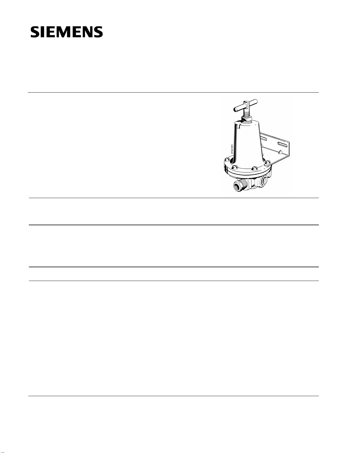
The RV 201 Pressure Reducing Valve (PRV) is a diaphragm-operated regulator
designed for precision control of air supply pressure to pneumatically operated
equipment.
• Instant response to sudden volume demands with negligible pressure drop.
• Supply pressure variations do not affect the stability of the reduced pressure.
• Built-in air relief feature makes it an excellent regulator for dead-end service.
• Die-cast aluminum with internal parts of brass.
201-1000 PRV (with mounting bracket).
Air connections
In and out 1/4” NPT
Outlet gauge ports
“L” plug 1/4” NPT
“R” reducing bushing 1/4” to 1/8” NPT
Maximum inlet pressure 250 psi (1724 kPa)
Reduced pressure range 3 to 60 psi (21 to 414 kPa)
Factory setting 18 psig (124 kPa)
Operating temperature range 40 to 120°F (4 to 49°C)
Capacity 8 cfm with pressure drop of 1 psi
Stability with variations in inlet pressures
from 25 to 100 psi (172 to 690 kPa)
the reduced pressure deviation is
approx. 0.5 psi (3.4 kPa)
Siemens Industry, Inc.
Page 2
Technical Instructions
Material
Complaint
Check
Probable Cause
Corrective Action
Document No. 155-137P25
March 8, 2005
Specifications
Mounting and
Installation
Adjustment
Diaphragm Buna-N
Disc Buna-N
Built-in relief for dead-end service Approx. 3 psi (21 kPa) differential
Weight 2 lb (0.9 kg)
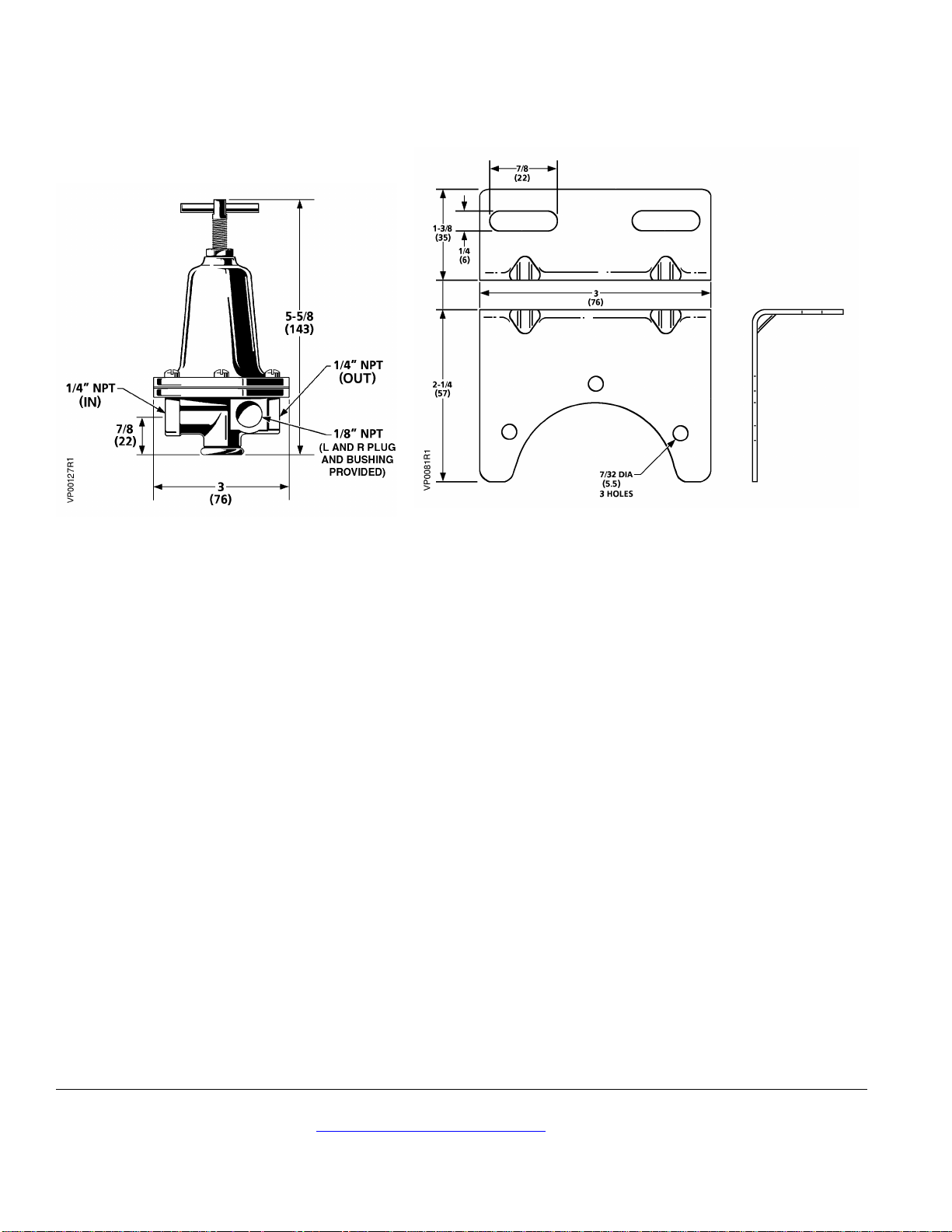
Dimensions See Figure 1
• Install a shut-off valve ahead of all equipment. It is recommended that a filter be
installed directly ahead of the PRV.
• Install the PRV as near as practical to the point of use or to the equipment it is
supplying.
• Be sure pipe ends are reamed clean to assure a smooth flow.
• Always blow out line to remove scale or other foreign matter.
• Apply pipe compound to male threads only and only enough to make tight joints.
• The piping connections are marked in each port on the underside of the PRV body.
The valve should be installed in the line so that the airflow is from IN to OUT.
Tappings L and R are normally for gauge use but may also be used for outlet or
service purposes in certain applications.
Changes in reduced pressures on the PRV can be made upward or downward without
bleeding or venting the reduced pressure system. To increase pressure, turn the
adjusting screw clockwise. To decrease pressure, turn the adjusting screw counterclockwise.
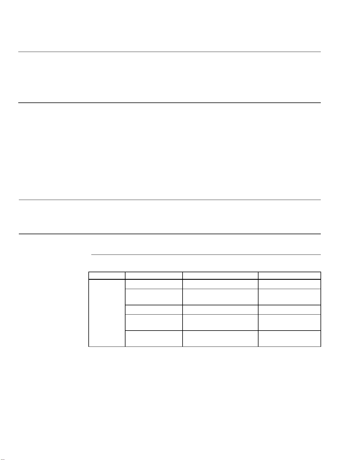
Troubleshooting
If the PRV pressure becomes unsteady, reduced, or deviates in excess of the normal
observed setting, replacement of the internal parts may be required. See Table 1.
Table 1. Troubleshooting.
Reduced
Pressure
Diaphragm Diaphragm stiff or swollen Replace diaphragm
Inner valve Inner valve dirty or worn,
Seat is scored
Filter Filter is dirty Clean filter
Supply v alve Supply valve not fully open Make sure the supply
Air leakage through
vent in cage
Dirty or worn inner valve
allows constant relief
Clean and/or replace
valve is wide open
Clean and/or replace
Page 2 Siemens Industry, Inc.
Page 3
Powers™ Controls RV 201 Pressure Reducing Valves Technical Instructions
155-137P25
March 8, 2005
Service
Replacement of
Diaphragm
Replacement of
Inner Valve
Repair Parts
To obtain best efficiency and longest periods of trouble-free service, the air supply must
be kept clean. Use a filter ahead of the PRV. Clean the filter periodically.
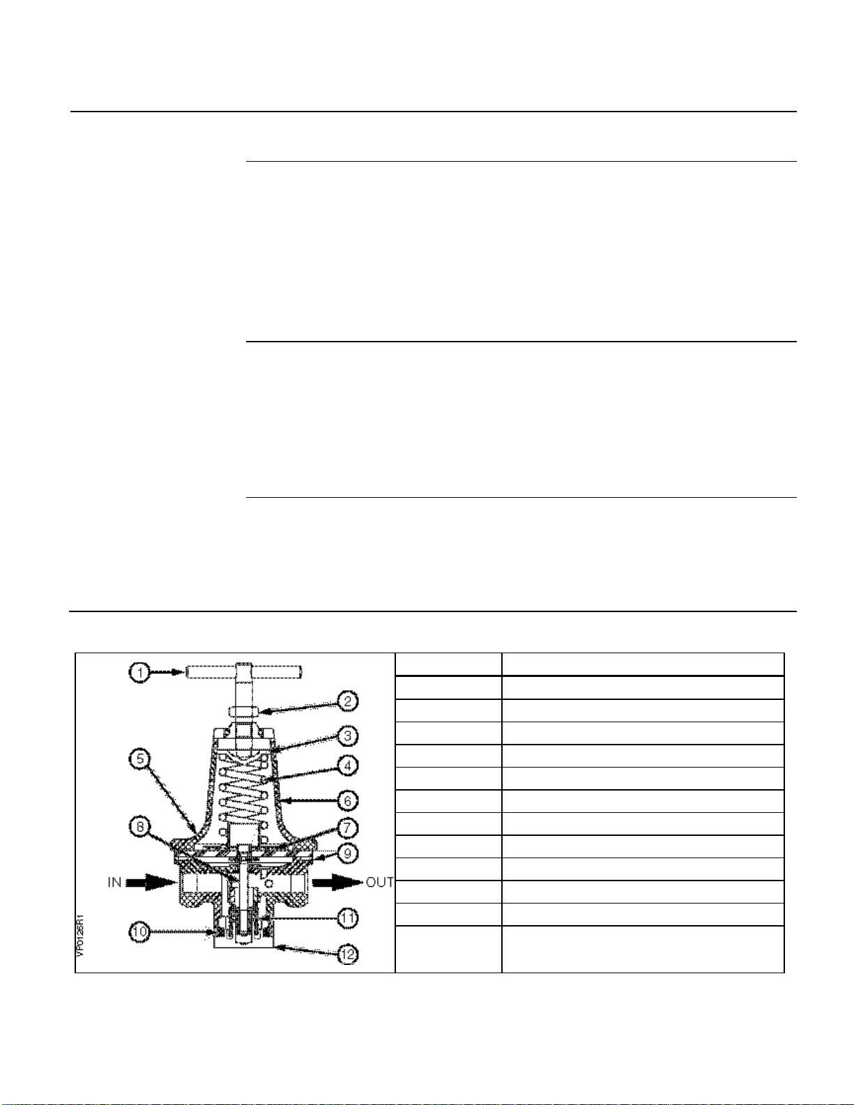
See Table 2.
1. Release spring tension by turning adjusting screw (1) counterclockwise.
2. Loosen the flange screws (5) and separate the upper (6) and lower housing
(9).
3. Remove diaphragm assembly (7) and replace it with a new assembly.
4. Reassemble the upper and lower housing and tighten the flange screws.
5. Reset the PRV as instructed in the Adjustment section.
See Table 2.
1. Remove bottom plug (12), poppet spring (11), and inner valve (8).
2. Wipe seat clean. Insert a new inner valve (8).
3. Reassemble the poppet spring (11) and bottom plug (12) with a new gasket
(10).
4. Reset the PRV as instructed in the Adjustment section.
For information on repair parts, contact:
Watts Fluid Air
9 Cutts Road
Kittery, ME 03904-0902
Phone: (207) 439-9511
Fax: (207) 439-5632
Table 2. Parts of the Pressure Reducing Valve.
Item Description
1 Adjusting screw
2 Check nut
3 Spring washer
4 Adjusting spring
5 Flange screw
6 Upper housing
7 Diaphragm assembly
8 Inner valve
9 Lower housing
10 Bottom plug gasket
11 Poppet spring
12 Bottom plug
Siemens Industry, Inc. Page 3
Page 4
Technical Instructions
Siemens Indus try, Inc.
+ 1 847-215-1000
Document No. 155-137P25
March 8, 2005
Figure 1. Dimensions of the Pressure Reducing Valve and Mounting Bracket.
Dimensions in Inches (Millimeters).
Information in this publication is based on current specifications. The company reserves the right to make changes in specifications and models as
design improvements are introduced. Powers is a registered trademark of Siemens Industry, Inc. Other product or company names mentioned
herein may be the trademarks of their respective owners. © 2005 Siemens Industry, Inc.
Building Technologies Division
1000 Deerfield Parkway
Buffalo Grove, IL 60089
Your feedback is important to us. If you have comments
about this document, please send them to
Document No. 155-137P25
Printed in the USA
Page 4
 Loading...