

SIELCO SISTEM SS 8014 User Manual
SIELCO SISTEMI srl
via Roma, 24 - 22070 Guanzate (CO) – Italy
Tel: +39 031899671 – Fax: +39 031976966
e-mail: info@sielcosistemi.com
website: http://www.sielcosistemi.com
SS 8014
SS 8014
Modbus TCP/IP server
4 isolated channels for
RTD, Resistance and
Potentiometer input
User Guide – MODBUS TCP/IP protocol
User Guide – MODBUS TCP/IP protocol
Firmware Version : 8300
Firmware Version : 8300
NOTES:
Registers and coils marked as RO in the column 'Access' are Read Only registers.
Registers and coils marked as R/W in the column 'Access' are Read and Write registers.
For the devices of SS8000 series, the group of data 0xxxx is the mirror of the group 1xxxx, the group of data 3xxxx is the mirror of the group 4xxxx,
therefore the first register could be addressed either as 30002 (with function 04) or 40002 ( with function 03).
The maximum number of coils that can be read through Modbus functions 01 and 02 (see "Supported modbus functions codes") are: 128
The maximum number of registers that can be read through Modbus functions 03 and 04 (see "Supported modbus functions codes") are: 64
The maximum number of registers that can be written by Modbus function 16 (see "Supported modbus functions codes") are: 64
The maximum number of coils that can be written by Modbus function 15 (see "Supported modbus functions codes") are: 64
All of the data shared by a device communicating by Modbus TCP/IP protocol are mapped in tables, at each data is associated a proper address.
Each data can be of two types:
- “REGISTER”, data of 2 bytes size (word of 16 bits) that can be associated to analogue input or output, variables, set-point, etc...
- “COIL”, data of 1 single bit that can be associated to digital input or output or to a logic state.
A register could contain the image (mirror) of more coils; in example the 16 digital inputs of a device could be read or written as bit (singularly)
addressing the coil related to each input or can be read or written as a single word addressing the associated register wherein each bit corresponds to
a coil.
In the Modbus protocol, registers and coils are divided as per the following groups of addresses:
0xxxx and 1xxxx = Coils (bit)
3xxxx and 4xxxx = Registers (word)
When reading functions are performed, use the tables indicated below to address the registers .
It is possible to access to the internal registers of the device by direct command Modbus TCP/IP or by the integrated web server.
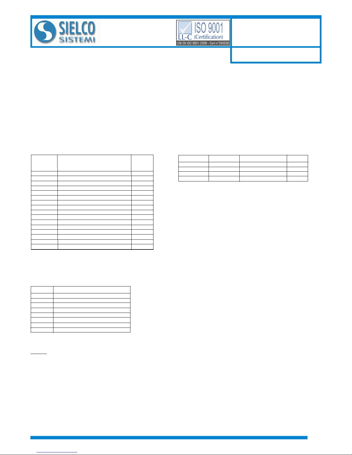
Function
01
02
03
04
05
06
15 (0F)
16 (10)
Description
Read Coil Status (0xxxx)
Read Inputs Status (1xxxx)
Read Holding Registers (4xxxx)
Read Inputs Registers (3xxxx)
Force Single Coil
Preset Single Register
Force Multiple Coil
Preset Multiple Registers
pag 1/4
(*)Coil (Hex)
0x00A1
0x00A2
0x00A3
Description
Watch-dog Enable
Watch-dog Event
Power-Up Event
Access
R/W
R/W
R/W
(*)Coil (Dec)
00161
00162
00163
PRELIMINARY DESCRIPTION
PRELIMINARY DESCRIPTION
REGISTERS TABLE
REGISTERS TABLE
COILS TABLE
COILS TABLE
SUPPORTED MODBUS FUNCTION CODES
SUPPORTED MODBUS FUNCTION CODES
Register
Position
40002
40003
40004
40005
40007
40011
40013
40031
40032
40033
40034
40036
40041
40042
40043
40044
Description
Firmware [0]
Firmware [1]
Name [0]
Name [1]
Node ID
System Flags
Watchdog timer
Input type Ch 0
Input type Ch 1
Input type Ch 2
Input type Ch 3
Break status
Analog Input (0) - Ch0
Analog Input (1) - Ch1
Analog Input (2) - Ch2
Analog Input (3) - Ch3
Access
RO
RO
R/W
R/W
R/W
R/W
R/W
R/W
R/W
R/W
R/W
RO
RO
RO
RO
RO
40004 / 40005 : NAME
Field of 2 read/write registers (4 bytes or 4 ASCII characters) available for the user, it can contain the name of the device or an abbreviation that
identifies its function inside the plant. Each one of the 4 bytes could be written by values from 0 to 255, ASCII characters included.
The default value of this field contains the identifier of the device expressed in ASCII characters.
- Default value: “8014” (ASCII).
40002 / 40003 : FIRMWARE
Field of 2 read only registers ; contains the firmware identifier provided by the manufactured.
- Default value: 8300 (hex)
DESCRIPTION MODBUS REGISTERS
DESCRIPTION MODBUS REGISTERS
40011 : SYSTEM FLAGS
Contains the enable bits and system events of the device. The following parameters are configurable:
Watchdog Event Enable: this bit allows to enable the Watchdog Event (0 = W atchdog disabled, 1 = Watchdog enabled). If this bit is active and the
device doesn't receive commands for the time specified in the register 40013 “Watchdog timer”, the PWR green led blinks.
If this function is required must be implemented at the power-on of the device; the bit must be reset manually when the Watchdog event is occurred.
Watchdog Event: if this bit is set as 1 indicates that the Watchdog condition has happened (0 = Normal condition; 1 = alarm condition)
PowerUp Event: this bit is forced to 1 at each power on and indicates that the device has been switched off or reset. With the setting of this bit as 0
and checking its state, it is possible to know if a reset of the device has occurred (0 = reset not occurred; 1 = reset occurred).
This bit must be reset manually.
40013 : WATCHDOG TIMER
Contains the value of the WatchDog timer, expressed in step of 1 second. If the WatchDog is enabled and the device doesn't receive commands in
a time lower or equal to the value of the one expressed in this register the W atchDog will be activated (see description register ”System Flags”).
- Default value: 10 (10 sec.)
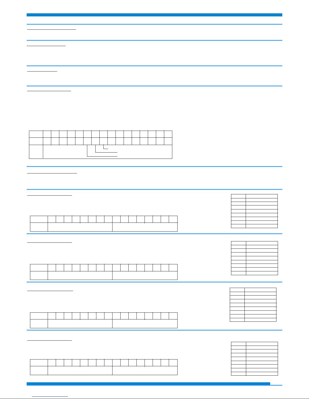
40031: INPUT TYPE Ch 0
This register shows the input type that is configured in relation to the type of sensor connected. The
table beside shows the types of sensors that can be connected to the input with the corresponding
value to write on the low part of register for the configuration of the input type.
- Default: Pt100 (0D Hex)
Bit
Descr.
15 14 13 12 11 10 09 08 07 06 05 04 03 02 01 00
Input type #0
40032: INPUT TYPE Ch 1
This register shows the input type that is configured in relation to the type of sensor connected. The
table beside shows the types of sensors that can be connected to the input with the corresponding
value to write on the low part of register for the configuration of the input type.
- Default: Pt100 (0D Hex)
Bit
Descr.
15 14 13 12 11 10 09 08 07 06 05 04 03 02 01 00
Input type #1
40033: INPUT TYPE Ch 2
This register shows the input type that is configured in relation to the type of sensor connected. The
table beside shows the types of sensors that can be connected to the input with the corresponding value
to write on the low part of register for the configuration of the input type.
- Default: Pt100 (0D Hex)
Bit
Descr.
15 14 13 12 11 10 09 08 07 06 05 04 03 02 01 00
Input type #2
40034: INPUT TYPE Ch 3
This register shows the input type that is configured in relation to the type of sensor connected. The table beside shows
the types of sensors that can be connected to the input with the corresponding value to write on the low part of register
for the configuration of the input type.
- Default: Pt100 (0D Hex)
Bit
Descr.
15 14 13 12 11 10 09 08 07 06 05 04 03 02 01 00
Input type #3
Value Type
00h Disabled
12h Res 0÷2000 Ohm
0Ch Res 0÷500 Ohm
0Dh Pt100
0Fh Ni100
0Eh Pt1000
10h Ni1000
11h Pot.< 500Ohm
Value Type
00h Disabled
12h Res 0÷2000 Ohm
0Ch Res 0÷500 Ohm
0Dh Pt100
0Fh Ni100
0Eh Pt1000
10h Ni1000
11h Pot.< 500Ohm
Value Type
00h Disabled
12h Res 0÷2000 Ohm
0Ch Res 0÷500 Ohm
0Dh Pt100
0Fh Ni100
0Eh Pt1000
10h Ni1000
11h Pot.< 500Ohm
Value Type
00h Disabled
12h Res 0÷2000 Ohm
0Ch Res 0÷500 Ohm
0Dh Pt100
0Fh Ni100
0Eh Pt1000
10h Ni1000
11h Pot.< 500Ohm
pag 2/4
Bit
Coil
Descr
15-14-13-12-11-10
163091620816107-06-05-04-03-02-01-00-
Watchdog Event enabling
Watchdog Event
Power-up Event
40007 : NODE ID
Contains the MODBUS address of the device; the values allowed are from 1 to 245 decimal.
This data is necessary for the correct addressing of the device into the Modbus net and must follow the IP address.
- Default value: Dec: 1, Hex: 01 INIT: Dec 245, Hex : F5.
 Loading...