

Siel SAFEPOWER EVO HFT Installation And Use Manual

IV404E Rev.000 SIEL S.p.A.
Issue date: 2017-06-05 Pag. 1 di 90 + FR
Uninterruptible Power Supply
Gruppo statico di continuità
SAFEPOWER-EVO-HFT
300-600kVA
INSTALLATION AND USE MANUAL
IV404E Rev.000 SIEL S.p.A.
Issue date: 2017-06-05 Pag. 2 di 90 + FR
Thank you for choosing our product.
The factory is highly specialized in the development and production of uninterruptible power supplies
(UPS). The UPSs of this series are high quality products, carefully designed and manufactured to ensure
optimum performance.
Symbols used in the manual
In this manual, some operations are shown by graphic symbols to alert the reader to the dangerous nature
of the operations:
Possibilit
y of serious injury or substantial damage to the device, unless
ade
quate precautionary countermeasures are taken.
This
symbol indicates some important information which must be read with
care
.
It is recommended to read this p
art of the manual.
IV404E Rev.000 SIEL S.p.A.
Issue date: 2017-06-05 Pag. 3 di 90 + FR
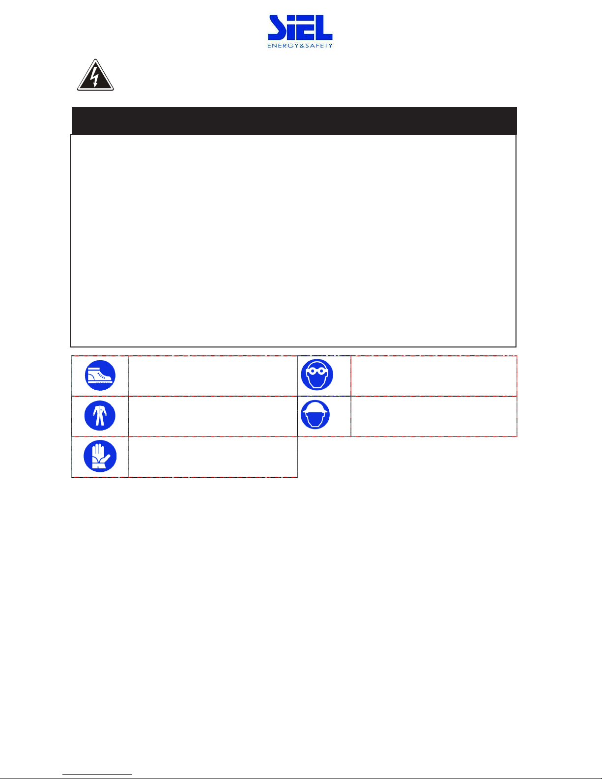
Protective equipment to be worn
No maintenance operations must be carried out on the device without wearing the Personal Protective
Equipment (PPE) described below.
Personnel involved in the installation or maintenance of the equipment must not wear clothes with wide
sleeves or laces, belts, bracelets or other items that may be dangerous, especially if they are metallic. Long
hair must be tied in such a way as to ensure that it is not a hazard.
The following signs show the protective equipment that should be worn. The various items of PPE must be
selected and sized according to the nature of the hazard (particularly electrical) posed by the equipment.
Accident
prevention footwear
Use
: always
Protective eyewear
Use
: always
Protective clothing
Use
: always
Helmet
Use
: When there are suspe
nded loads
Work gloves
Use
: always

IV404E Rev.000 SIEL S.p.A.
Issue date: 2017-06-05 Pag. 4 di 90 + FR
Definition of “operator” and “specialized technician”
The professional figure responsible for accessing the equipment for ordinary maintenance purposes is
defined with the term operator.
This definition covers personnel that know the operating and maintenance procedures for the equipment,
and that have been:
1. trained to operate in accordance with the safety standards relating to the dangers that may arise
where electrical voltage is present;
2. trained to use Personal Protective Equipment and to carry out basic first aid.
The professional figure responsible for the installation and start-up of the equipment, and for any
extraordinary maintenance, is defined with the term specialized technician.
This definition covers personnel that, in addition to the requirements listed above for a general operator,
must also:
1. have been suitably trained by the manufacturers or their representative.
2. be aware of installation, assembly, repair and service procedures, and have a specific technical
qualification.
3. must have a background of technical training, or specific training relating to the procedures for the
safe use and maintenance of the equipment.
IV404E Rev.000 SIEL S.p.A.
Issue date: 2017-06-05 Pag. 5 di 90 + FR
Emergency interventions
The following information is of a general nature.
First aid interventions
Company regulations and traditional procedures should be followed for any first aid intervention that may
be required.
Firefighting measures
1. Do not use water to put out a fire, but only fire extinguishers that are suitable for
use with electrical and electronic equipment.
2. If exposed to heat or fire, some products may release toxic fumes into the atmosphere. Always use
a respirator when extinguishing a fire.
IV404E Rev.000 SIEL S.p.A.
Issue date: 2017-06-05 Pag. 6 di 90 + FR
GENERAL PRECAUTIONS
This manual contains detailed instructions for the use, installation and start-up of the
SAFEPOWER EVO HFT
. Read the manual carefully before installation. For informati
on on using
the
SAFEPOWER EVO HFT, the manual should be kept close at hand and consulted before
carrying out any operation on the
device.
This device has been designed and manufactured in accordance with the standards for the product, for
normal use and for all uses that may reasonably be expected. It may under no circumstances be used for
any purposes other than those envisaged, or in any other ways than those described in this manual. Any
interventions should be carried out in accordance with the criteria and the time-frames described in this
manual.
PRECAUTIONS AND SAFETY REGULATIONS
Refer to the “Safety and Compliance Manual” supplied with the UPS (0MNA141_NE).
ENVIRONMENTAL PROTECTION
In the development of its products, the company devotes abundant resources to analysing the
environmental aspects.
All our products pursue the objectives defined in the environmental management system
developed by the company in compliance with applicable standards.
No hazardous materials such as CFCs, HCFCs or asbestos are used in this product.
When evaluating packaging, the choice of material has been made favouring recyclable materials.
For correct disposal, please separate and identify the type of material of which the packaging is made in
the table below. Dispose of all material in compliance with applicable standards in the country in which the
product is used.

IV404E Rev.000 SIEL S.p.A.
Issue date: 2017-06-05 Pag. 7 di 90 + FR
DESCRIPTION
MATERIAL
Box
Cardboard
Protective bag
Polythene
Accessories bag
Polythene
DISPOSING OF THE PRODUCT
The UPS contain electronic cards and batteries which are considered TOXIC and HAZARDOUS waste. When the
product reaches the end of its operating life, dispose of it in accordance with applicable local legislation.
Disposing of the product correctly contributes to respecting the environment and personal health.
No reproduction of any part of this manual, even partial, is permitted without the Factory. authorization.
The Factory reserves the right to modify the product described herein, in order to improve it, at any time
and without notice.

IV404E Rev.000 SIEL S.p.A.
Issue date: 2017-06-05 Pag. 8 di 90 + FR
CONTENTS
1. PRELIMINARY OPERATIONS ............................................................................... 10
1.1 Removing the packaging and positioning the device ................................................... 10
1.2 Storage ......................................................................................................................... 10
1.3 Handling ....................................................................................................................... 11
2. INSTALLATION ENVIRONMENT ........................................................................... 12
2.1 Ambient conditions:...................................................................................................... 13
2.2 Dimensions of the premises ......................................................................................... 13
2.3 Cooling of the premises ................................................................................................ 14
2.4 Air change for battery premises ................................................................................... 15
3. SAFEPOWER EVO HFT IN SINGLE CONFIGURATION ............................................ 16
3.1 Set-up of the electrical system ..................................................................................... 16
3.1.1 Input ................................................................................................................................... 16
3.1.2 Selectivity ........................................................................................................................... 18
3.1.3 Battery ............................................................................................................................... 20
3.1.4 Differential (RCD) ............................................................................................................... 20
3.1.5 Backfeed protection ........................................................................................................... 24
3.1.6 Emergency power off device (EPO) .................................................................................... 24
3.2 Mains, load and battery connections ........................................................................... 25
3.3 Connection of signals and remote commands ............................................................. 29
3.3.1 EPO connector (emergency power off control).................................................................. 29
3.3.2 REMOTE COMMANDS AND ALARMS ................................................................................. 29
3.3.3 RS232 ................................................................................................................................. 31
3.3.1 Parallel (optional) .............................................................................................................. 32
3.3.2 SLOTS 2-1 , the following cards may be inserted (optional): ............................................. 33
3.3.3 REMOTE ALARMS (2 optional cards) ................................................................................. 33
3.3.4 MODEM (optional) ............................................................................................................ 34
3.3.5 MULTI I / O (optional) .................................................................................................... 34
3.3.6 REMOTE PANEL (OPTIONAL).............................................................................................. 34
3.3.7 Dual Bus System – UGS (optional) ..................................................................................... 35

IV404E Rev.000 SIEL S.p.A.
Issue date: 2017-06-05 Pag. 9 di 90 + FR
3.3.1 SWOUT and SWMB aux - External temperature sensor(optional). ................................... 36
3.4 Start-up procedure ....................................................................................................... 38
3.4.1 Battery operation check ..................................................................................................... 41
3.5 Operating modes .......................................................................................................... 42
3.5.1 On - line - factory setting - ................................................................................................ 42
3.5.2 Standby-on / Smart active ................................................................................................. 42
3.5.3 Standby-off (with mains present the load is not powered) .............................................. 44
3.5.4 Stabilizer (operation in on-line mode without battery) .................................................... 44
3.5.5 Frequency converter (from 50 to 60Hz or vice versa) ........................................................ 45
3.6 Personalizations ........................................................................................................... 46
3.7 Procedure to transfer the load from UPS onto maintenance by-pass. ........................ 46
3.8 UPS and load shutdown ................................................................................................ 49
3.9 Block diagram ............................................................................................................... 50
3.10 Components of the block diagrams .............................................................................. 51
4. SAFEPOWER EVO HFT IN PARALLEL CONFIGURATION ........................................ 54
4.1 Introduction .................................................................................................................. 54
4.2 Electrical system set-up ................................................................................................ 55
4.2.1 Input ................................................................................................................................... 55
4.2.2 Differential ......................................................................................................................... 55
4.2.3 Emergency power off device (EPO) .................................................................................... 56
4.2.4 External maintenance by-pass. .......................................................................................... 57
4.3 Mains, load and battery connections. .......................................................................... 58
4.3.1 UPS AC input / output power connection .......................................................................... 58
4.3.2 Power connections battery side. ........................................................................................ 60
4.4 Connection of signals .................................................................................................... 63
4.5 Start-up procedure ....................................................................................................... 69
4.6 Operating modes .......................................................................................................... 71
4.7 By-pass for maintenance .............................................................................................. 75
5. MAINTENANCE .............................................................................................. 80
6. GENERAL CHARACTERISTICS .............................................................................. 82
7. APPENDIX A - REMOTE COMMANDS AND ALARMS CARD - ........................................ 87

IV404E Rev.000 SIEL S.p.A.
Issue date: 2017-06-05 Pag. 10 di 90 + FR
1. Preliminary operations
1.1 Removing the packaging and positioning the device
On delivery, the packaging must be inspected to ensure that it is whole and that it has not been crushed or
dented. Check in particular that neither of the two impact resistant devices on the packaging is red; if one
of them is red, follow the instructions on the packaging.
The essential details of the device are provided on the shipping document. The marking, weight and
dimensions of the various items making up the packing list are shown.
Check the state of the device by means of a visual inspection of both the inside and the outside. Any dents
seen mean that it has suffered knocks during shipping, which could compromise the normal operation of
the device.
1.2 Storage
In the following situations:
- installation not immediately after delivery;
- de-installation and storage while awaiting relocation,
place the device in covered premises that are protected from direct contact with atmospheric agents and
dust. The following environmental values are those allowed in the storage area:
Temperature: -25 ÷ + 70 °C
Relative humidity: 30÷90 % max.
IV404E Rev.000 SIEL S.p.A.
Issue date: 2017-06-05 Pag. 11 di 90 + FR
For the installation of a battery cabinet, if provided with the uninterruptible power supply,
follow the instructions given in the specific manual.
The list of material provided may vary depending on the order specifications. As a general rule, the
packaging should include the following: this manual, the installation drawing, the warranty and eventual
accessories.
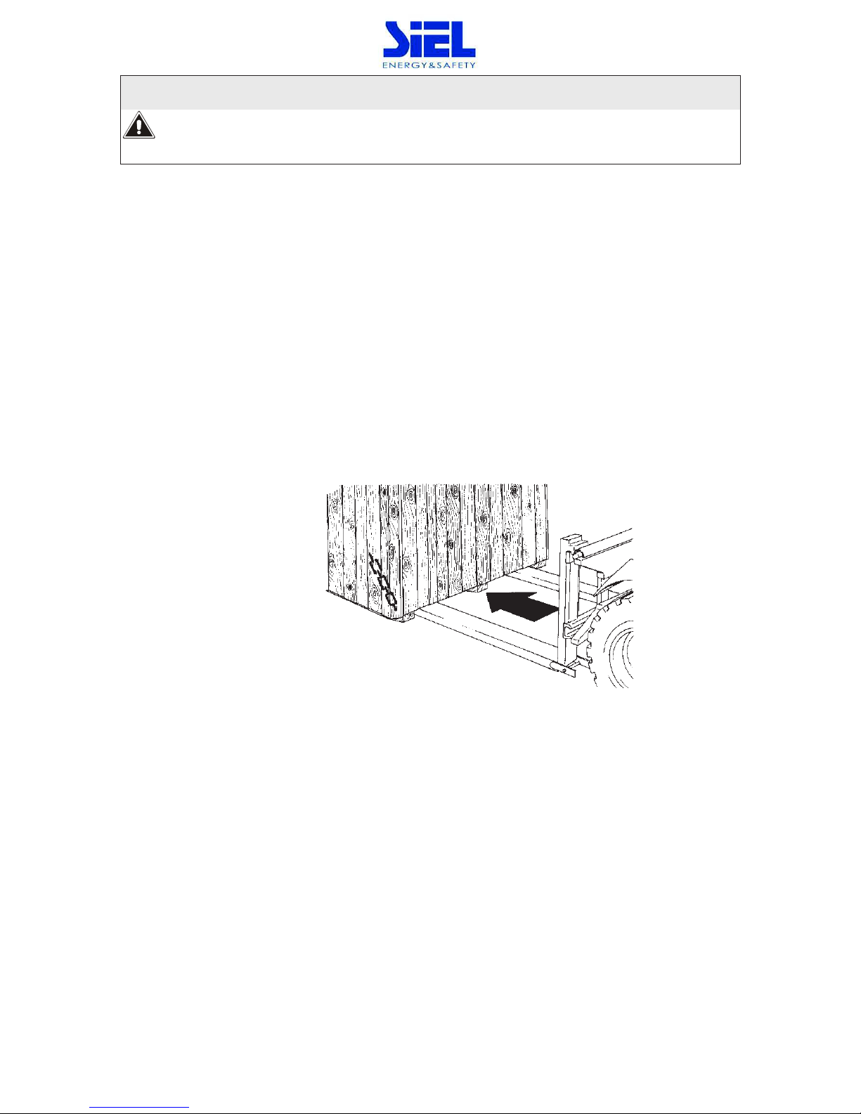
1.3 Handling
The equipment must only be handled by adequately trained personnel. It can be unloaded from the vehicle
and put into place by lifting the box or the wooden deck to which the equipment is secured with a fork-lift
truck. A transpallet or fork-lift truck should be used for the permanent positioning of the equipment, in
accordance with the instructions provided below.
IV404E Rev.000 SIEL S.p.A.
Issue date: 2017-06-05 Pag. 12 di 90 + FR
1 Insert the forks of the fork-lift truck in the lower part of the device, from the front or back, and
ensure that they stick out about 30 cm on the other side.
If a transpallet is used, raise the device only as much as is strictly necessary.
2 Secure the device to the transpallet or fork-lift before moving it.
Risk of overturning
In order to avoid the risk of the device overturning, ensure that it is firmly secured to the
transpallet or fork
-lift truck by means of appropriate ropes before moving it.
When being moved the cabinet should be handled with care; knocks or drops can damage it. Once in
position, remove the packaging carefully in order not to scratch the device.
The packaging should be removed as follows:
1. Cut the bands
2. Slide away the carton from above.
3. Remove the screws securing the cabinet to the wooden base.
4. If using a transpallet, remove the device from the pallet and set it on the floor, using
the same precautions as set out in the section on Handling.
2. Installation environment
The SAFEPOWER EVO HFT and the battery cabinet have been designed for indoor installation. The choice
of premises for installation should comply with the points set out below.

IV404E Rev.000 SIEL S.p.A.
Issue date: 2017-06-05 Pag. 13 di 90 + FR
2.1 Ambient conditions:
ensure that the floor can support the weight of the UPS and of any battery cabinet that may be
used;
avoid dusty environments;
avoid narrow environments that could hinder normal maintenance operations;
avoid placing the device in areas exposed to direct sunlight or heat;
ensure that the ambient temperature conforms to the following:
minimum operating temperature: 0 °C
maximum temperature for 8 hours a day: + 40°C
average temperature for 24 hours: + 35°C
max relative humidty: 90 % without condensation
Max installation height: 1000 m at rated power
(-1% power for every 100 m above 1000 m) max 4000 m
2.2 Dimensions of the premises
For the mechanical dimensions of the cabinets, refer to the “INSTALLATION DRAWINGS” supplied with the
UPS and with the battery cabinet, if present. These drawings provide the following data:
the position of the holes in the base to secure the device to the floor, if applicable;
the view of the floor support for the sizing of a structure to raise the cabinet, if applicable;
the position of cable entry;
the position of the fans on the top of the UPS, for the positioning of a structure to convey the
warm air discharged by the equipment outside the premises, if applicable;
the input, output and battery cables section;
the power dissipated by the equipment (kW).
IV404E Rev.000 SIEL S.p.A.
Issue date: 2017-06-05 Pag. 14 di 90 + FR
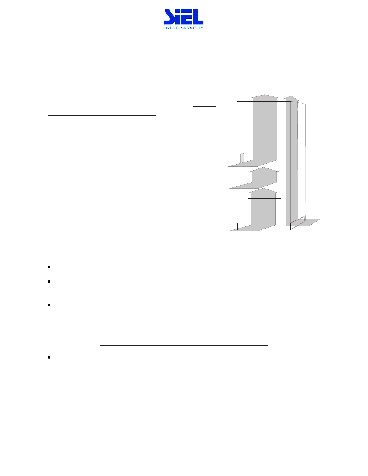
2.3 Cooling of the premises
The recommended operating temperature for the lifetime of the UPS and of the batteries is between 20 and
25°C. The lifespan of the battery depends on the operating
temperature; with an operating temperature of between 20°C and
30°C, the lifespan of the batteries is halved
.
A heat dissipation system is required to keep the temperature of the
premises housing the equipment within the field 20÷25°C.
The heat dissipation needed for the correct operation of the UPS is
brought about by the air current made by the fans located inside the
UPS (forced convection) and by the air around the side panels
(natural convection).
In order to ensure proper air circulation, and therefore the correct
operation of the UPS, measures must be taken during installation to
avoid any obstructions to the free circulation of air. These include the following:
ensure a distance of at least 60 centimetres from the ceiling, so as not to hinder air extraction,
leave a free space of at least one metre at the front of the equipment to ensure both the circulation of
the air and installation and maintenance operations;
With natural convection the thermal load is dissipated to the outside through the walls; thus a cabinet
placed against a wall or in a hollow dissipates less heat than one located in a free environment.
The following rule must be observed:
leave at least one of the three side walls free: right, left or back.
the side strips must not be mounted for installations where cabinets are placed side by side.

IV404E Rev.000 SIEL S.p.A.
Issue date: 2017-06-05 Pag. 15 di 90 + FR
2.4 Air change for battery premises
The premises housing the battery cabinet must have sufficient air circulation to ensure that the
concentration of hydrogen issued during battery charging is kept below the danger limit.
The air change in the premises should preferably be provided by natural ventilation, otherwise by forced
ventilation.
The standard EN 50272-2 for air change envisages that the minimum opening must satisfy the following
equation:
A = 28 x Q = 28 x 0.05 x n x Igas x C10 (1/10³) [cm²]
where: A = free opening for air intake and outlet
Q = flow of air to be removed [m³/h]
n = number of battery elements;
C10 = battery capacity over 10 hours [Ah]
Igas = current that produces gas [mA//Ah]
in accordance with the standard: Igas = 1 VRLA type battery (*)
(*) for open vase or nickel batteries, contact the battery manufacturer.
When the equation is applied for 240 element (40 battery) hermetically-sealed lead batteries:
A = 336 x C10 / 10³ [cm²]
When using 120Ah batteries, the minimum aperture should be approximately:
A = 41 [cm²]
The air intake and outlet must be positioned to ensure the best possible circulation; for
example
:
- apertures on opposite walls,
- a minimum distance of 2 m when they are on the same wall
.
IV404E Rev.000 SIEL S.p.A.
Issue date: 2017-06-05 Pag. 16 di 90 + FR
3. SAFEPOWER EVO HFT in single configuration
3.1 Set-up of the electrical system
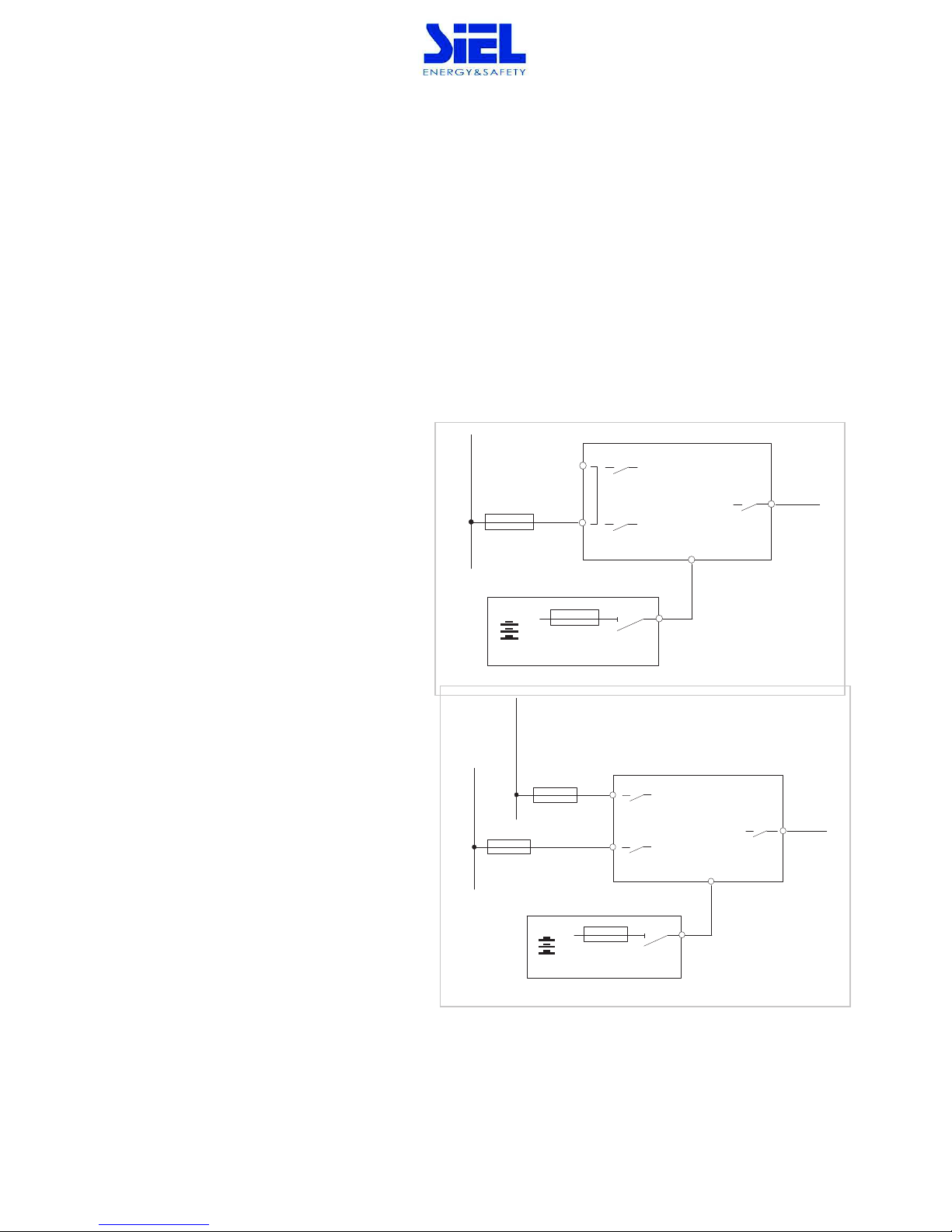
3.1.1 Input
The UPS input must have a max. current protection device for the section of line coming from the
distribution panel as well as for the two inputs into the SAFEPOWER EVO HFT: the rectifier line and the
by-pass line.
The protection device should be sized according to the situation, as follows:
a) single power line
b) main power supply and separate by-pass
a) Single power line
The UPS input must have a max. current
protection device for the section of line
coming from the distribution panel. The fuse
represented with the letter F.
b)main power supply and separate bypass
When there are two separate power lines, the
main power line and the by-pass line, two
protection devices must be provided
(indicated with the letters F and G in the
drawing b), one for each line.
MAINS LINE
+/-
LOAD
UPS
BATTERY CABINET
F
SWBY
SWIN
SWOUT
MAINS LINE
+/-
LOAD
UPS
BATTERY CABINET
F
SWBY
SWIN
SWOUT
BY-PASS LINE
G

IV404E Rev.000 SIEL S.p.A.
Issue date: 2017-06-05 Pag. 17 di 90 + FR
300
400
500
600
Input line
Imax (
100% load, and battery recharging)
476
635
794
953
External [F] fuse type gG (*) [A]
630
800
1000
1200
(*) or equivalent circuit breakers
IV404E Rev.000 SIEL S.p.A.
Issue date: 2017-06-05 Pag. 18 di 90 + FR
3.1.2 Selectivity
The system where the UPS is
inserted must be set up in such
a way that in the event of a
shortcircuit on one of the lines
downstream of the UPS, the
fuse on the output opens while
the upstream fuse normally
works. This is known as
selectivity, and ensures that the
remaining feeders maintain the
power supply.
In order to select the correct protection devices to be inserted downstream of the SAFEPOWER EVO HFT,
the following two operating modes have to be taken into consideration: mains power supply
and battery
power supply.
With mains power supply
the output fuse must be selective with the input fuse; the condition is verified
for the following values:
[kVA]
300
400
500
600
Rated output current:
[A]
433
578
722
867
Type gG fuse used at the UPS input
(as shown in the
table of connections)
[A]
500 630 800 1000
Maximum fuse at the UPS output for selectivity:
Fuse size for type gG fuse
[A]
315 400 500
630
Fuse size for type aM fuse
[A]
200 250 315
400
At least two feeders are necessary in order to use the UPS at rated load with fuses of type gG.
H
+/-
LOAD
UPS
SWBY
SWIN
SWOUT
+/-
BATTERY CABINET

IV404E Rev.000 SIEL S.p.A.
Issue date: 2017-06-05 Pag. 19 di 90 + FR
With battery power supply
( first fault) in the event of a shortcircuit on one of the outputs (second fault)
it must be possible for the fuse to be open before the inverter shuts down.
If the shortcircuit is of the three-phase type, the inverter can supply a current for 1 second that is 1.8 times
the value of the rated current of the UPS output (with a single phase shortcircuit the current is around 3
times the value).
In the worst-case scenario, that is a three-phase shortcircuit then a smaller current, the condition occurs if:
[kVA]
300
400
500
600
Rated output current:
[A]
433
578
722
867
Shortcircuit current (three-phase) 1.8 times the rated output current for 1
second
Maximum fuse at the UPS output for selectivity:
Fuse size for type gG fuse [A]
125
125
160
200
Fuse size for type aM fuse
[A]
80
100
125
160
At least five feeders are necessary in order to use the UPS at rated load with fuses of type gG.
To sum up, when there is a shortcircuit on the output, there are two alternatives if only the line affected by
the shortcircuit is to be isolated; let us consider the example of the 300kVA:
selectivity with both mains power supply and battery power supply;
the load has to be shared between at least five feeders, each sized at 20% of the rated power.
selectivity, with mains power supply only:
since it is considered unlikely that after a first fault a second fault will occur in the limited time
of operation from the battery
, it is sufficient to share the output between two lines, each sized
for 50% of the rated power.
IV404E Rev.000 SIEL S.p.A.
Issue date: 2017-06-05 Pag. 20 di 90 + FR
3.1.3 Battery
Battery cabinet
For connection to the UPS, the battery cabinet must have an overcurrent protection device and
a disconnecting device.
The disconnector may be closed
only when the UPS is started up regularly; see the section
“Start
-up procedure” on page 38.
The function of the fuses is to protect the batteries and the cables from a shortcircuit between the battery
cabinet and the UPS. The following rules should be observed for their sizing:
if rapid fuses of the type gl / gG are installed: the maximum size of fuse to be used is 2
times the battery capacity in Ah.
If ultra rapid fuses of the type aR are installed: the maximum size of fuse to be used is 2.5
times the battery capacity in Ah.
For example: the following fuses may be used for batteries of the type 150Ah: 315A type gl/gG or 355A
type aR.
For the section of the cable for the UPS to battery connection refer to the following current value:
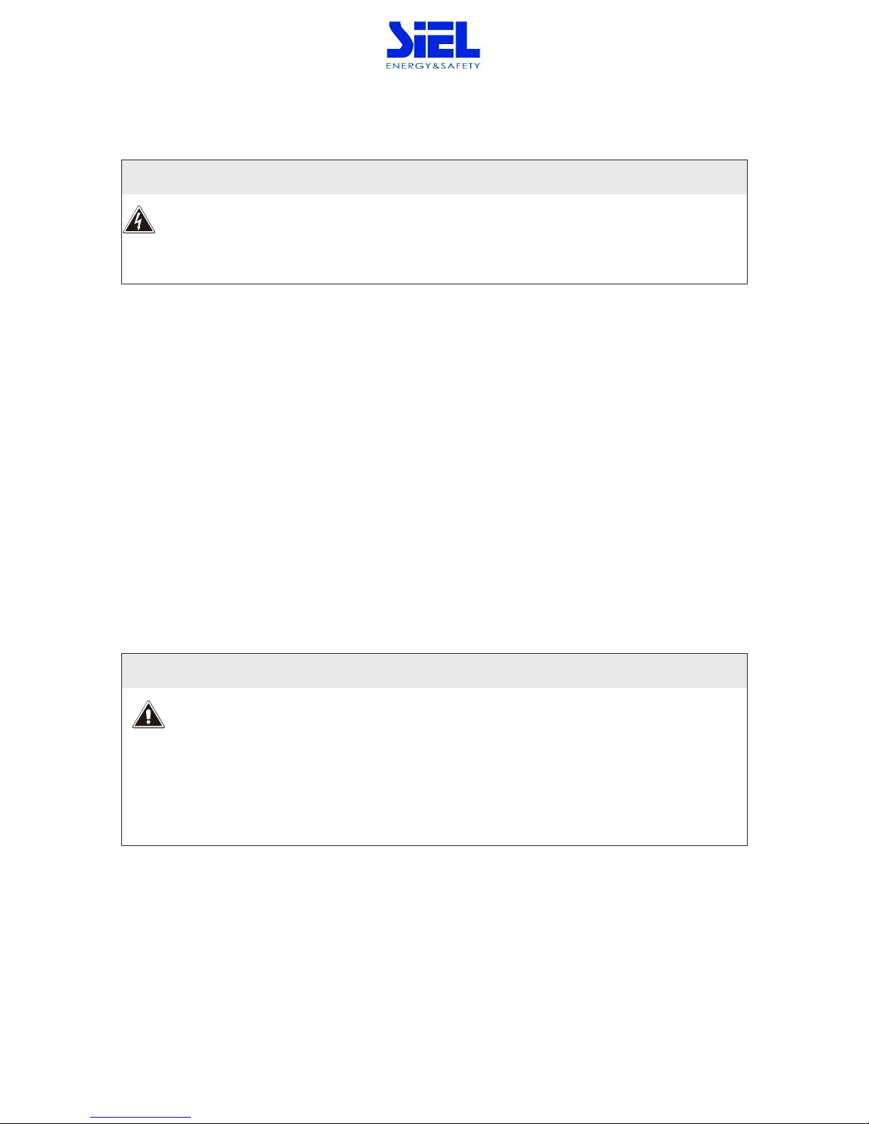
3.1.4 neutral conductor
Do not connect the output neutral to ground.
The use of an isolation transformer o n t h e b yp a ss lin e is required should it be
necessary
to
modify the neutral arrangements downstream of UPS.
[kVA]
300
400
500
600
Battery
Permanent battery eq. Current
[A]
675
900
1150
1300
IV404E Rev.000 SIEL S.p.A.
Issue date: 2017-06-05 Pag. 21 di 90 + FR
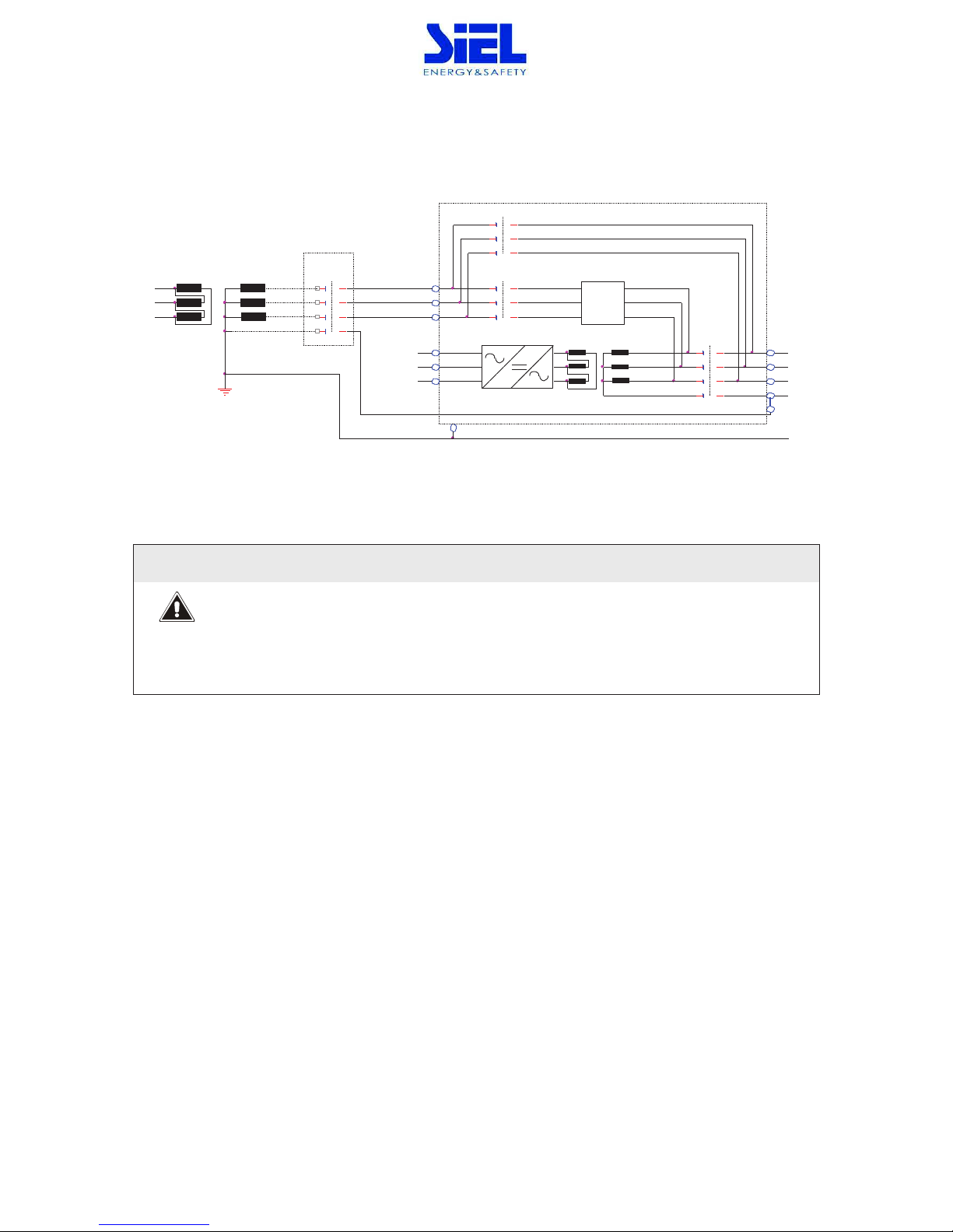
300-400kVA
In normal operation SWBY and SWOUT switches are closed, the opening of the SWBY do not change the
state of the neutral output system
300-400kVA
The neutral state is not a function of position of the bypass line switch.
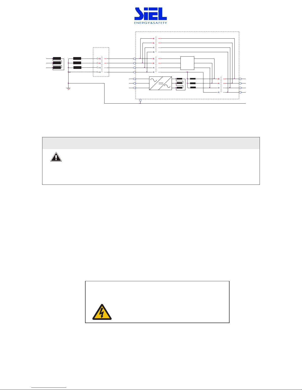
500-600kVA
In normal operation SWBY and SWOUT switches are closed, the opening of the SWBY change the state of
the neutral output system
L2
L1
N
L3
L3
L1
L2
L2
L3
L1
Static
Switch
SWMB
SWBY
SWOUT
PE
L1
L2
L2
L1
N
L3
L3
PE
PE
(*)
UPS
IV404E Rev.000 SIEL S.p.A.
Issue date: 2017-06-05 Pag. 22 di 90 + FR
500-600kVA
The neutral state is function of position of the bypass line switch.
NOTE (*): place the label supplied (The following label, supplied with the UPS,
must
be
displayed
on
all
switching devices
located upstream in the
same
electrical
system
as the UPS):
Before working on this circuit
- Isolate Uninterruptible Power System (UPS)
-Then check for Hazardous Voltage between all terminals
including the protective earth
Risk of Voltage Backfeed
L1
N
L3
L2
L1
L2
L3
L1
L2
L3
Static
Switch
SWMB
SWBY
SWOUT
PE
L2
L1
L2
N
L3
N
L3
L1
PE
PE
UPS
(*)

IV404E Rev.000 SIEL S.p.A.
Issue date: 2017-06-05 Pag. 23 di 90 + FR
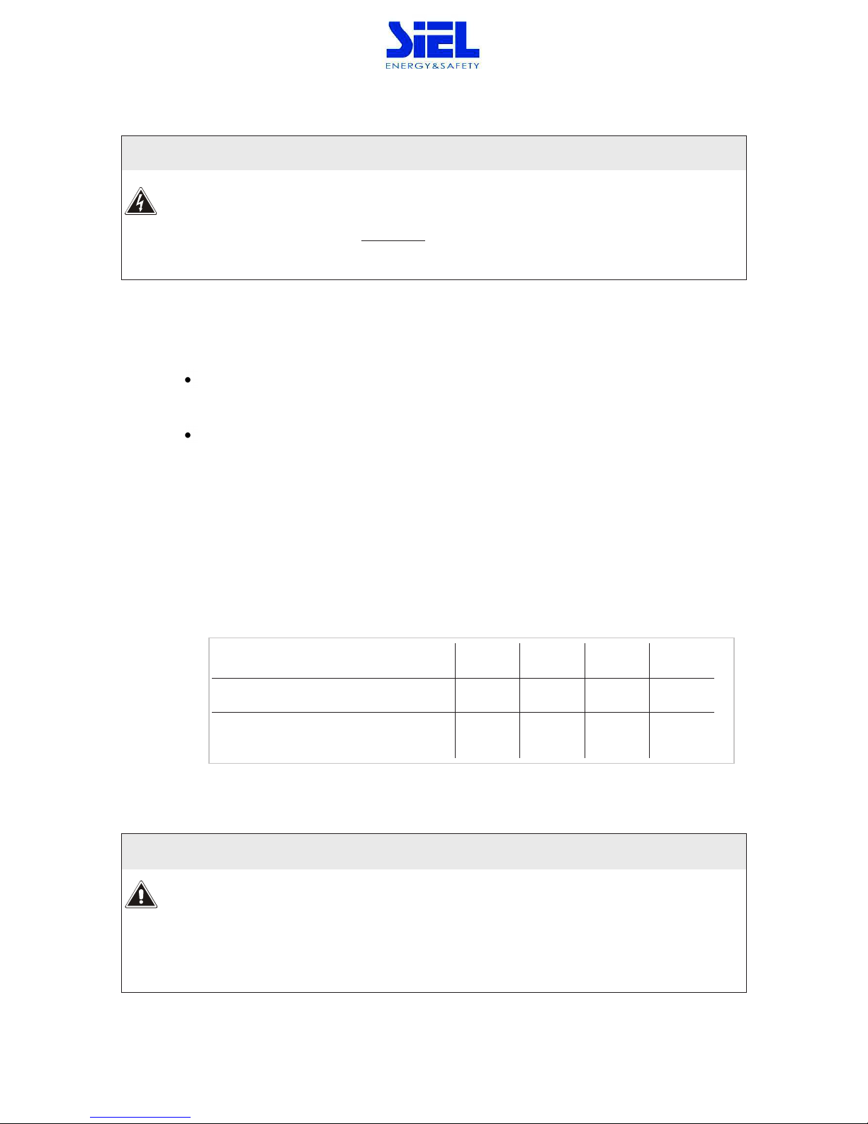
3.1.5 Differential (RCD)
If the SAFEPOWER EVO HFT protection against electric shock uses differential current devices (RCD),
these have to have the following characteristics:
- Sensitivity 300mA
- sensitive direct current and unidirectional components (class B)
- insensitive to transient current pulses
- delay greater than or equal to 0.1 s.
When operating in the presence of mains supply, a differential breaker (RCD) installed on the input will
intervene as the output circuit is not isolated from the input circuit.
When operating without mains supply (from battery) the input differential breaker will intervene only if it
is able to switch as a result of leakage current without any voltage at its poles (for example a differential
breaker with an auxiliary relay is not suitable). However it is possible to install additional differential
breakers on the output of the UPS, possibly coordinated with those on the input.
IV404E Rev.000 SIEL S.p.A.
Issue date: 2017-06-05 Pag. 24 di 90 + FR
3.1.6 Backfeed protection
The SAFEPOWER EVO HFT is provided with a device to prevent voltage backfeed on the input line due to
an internal fault. This protection device works by switching off the inverter if the current flow is faulty,
thereby causing voltage backfeed on the by-pass line during operation from the inverter. If the fault occurs
when the UPS is operating from the battery, the load will not be powered.
Should it be required to avoid the shutting down of the inverter in order to keep the load powered by the
inverter even in the event of a double fault, the system can be customized to control the opening coil of a
switch located upstream by reprogramming one of the relays on the “REMOTE COMMANDS AND ALARMS”
card.
The control logic allows the function of the relay to be reconfigured, for example for the backfeed alarm,
and then the free voltage contact can be used to control the triggering of a switch located on the UPS
input.
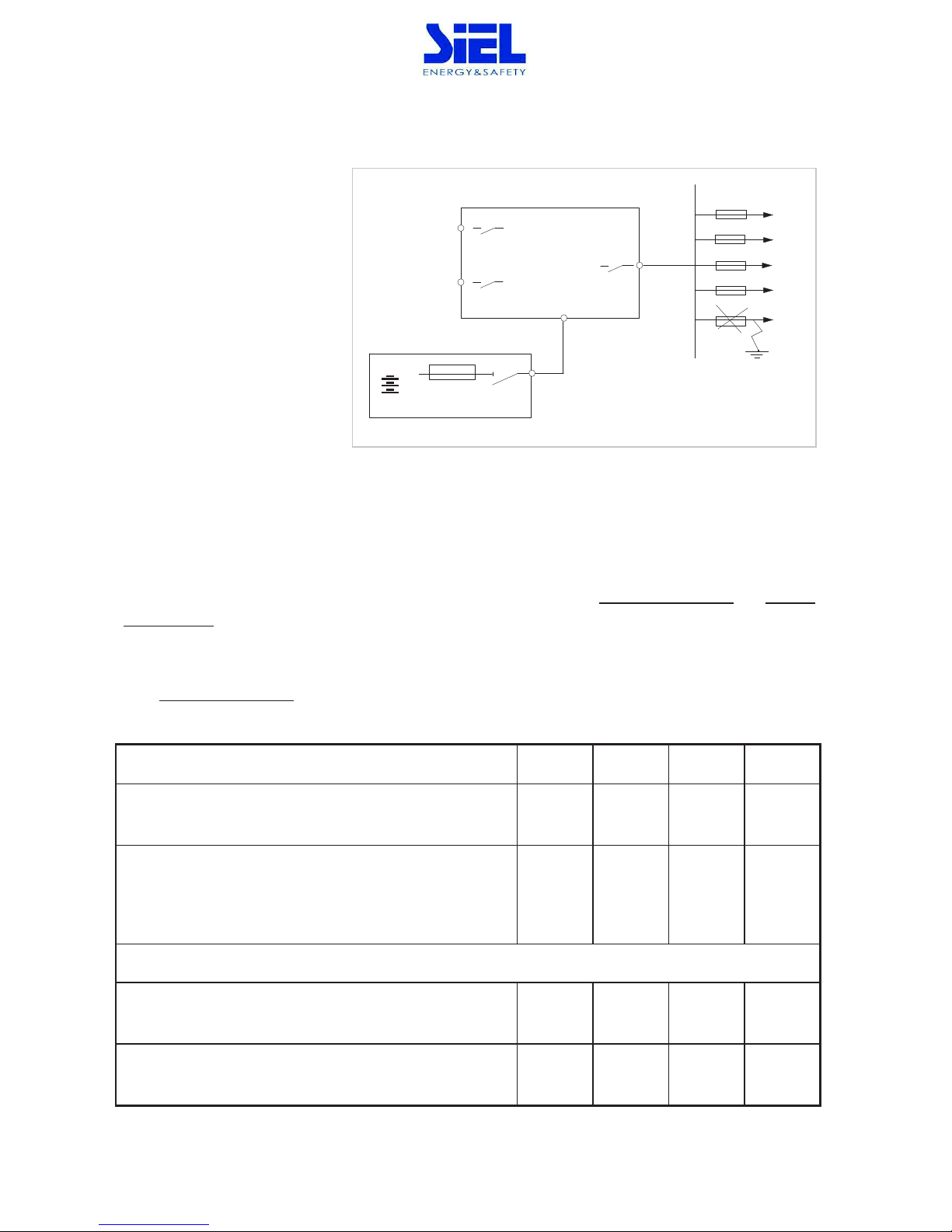
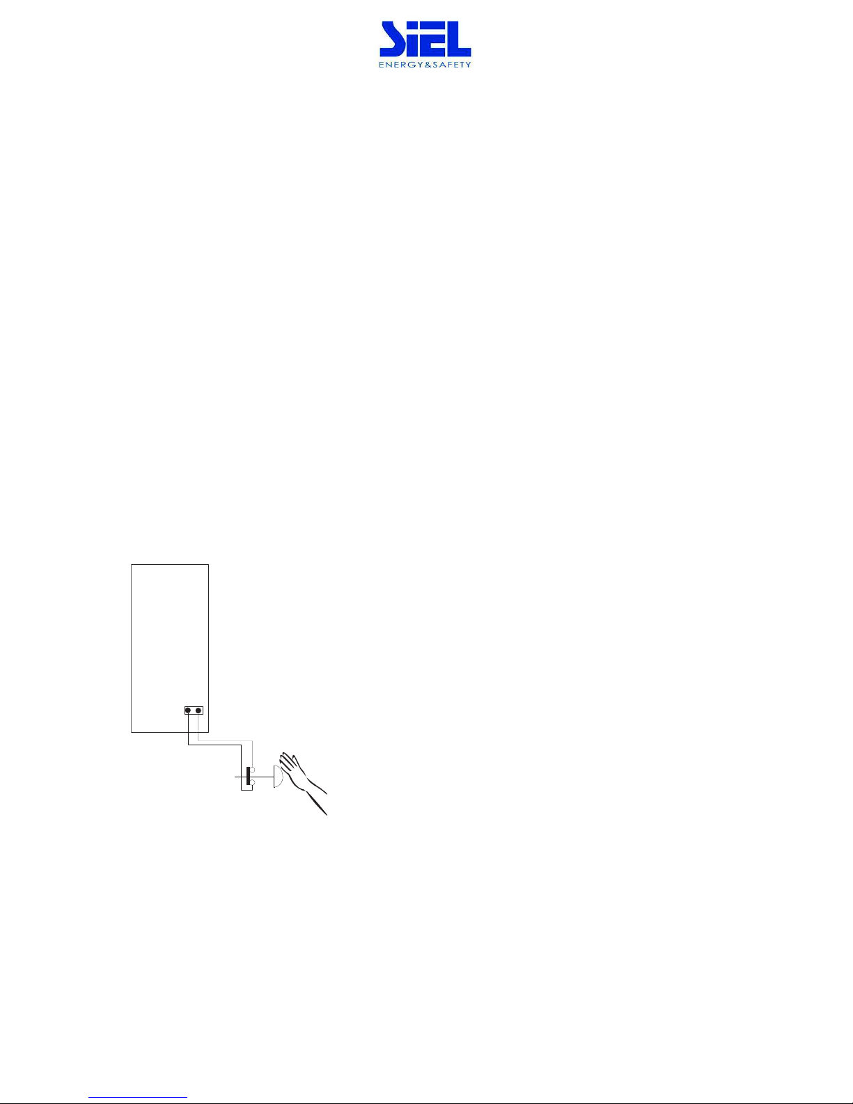
3.1.7 Emergency power off device (EPO)
The UPS is pre-set to be connected to a remote emergency power off device as laid down in standard EN
62040-1-2. If the remote device (not supplied with the equipment) is activated, the inverter output voltage
is cut.
The connection procedure is shown below.
a - EPO terminal board located on the UPS
b - EPO switch (not provided).
On the SAFEPOWER EVO HFT, the jumper on the EPO terminals (page 29) must be removed, and the wires
from the auxiliary contact of the button must be connected in place of the jumper.
The contact must be closed with the button in the rest position and must open when the button is
pressed.
UPS
a
b
IV404E Rev.000 SIEL S.p.A.
Issue date: 2017-06-05 Pag. 25 di 90 + FR
3.2 Mains, load and battery connections
The operations described in this chapter must be carried out exclusively by a specialized
technician. The first connection to be made is the earth conductor.
The SAFEPOWER EVO HFT MUST NOT OPERATE WITHOUT AN EARTH CONNECTION
Before making the connection, open all the switches on the device and ensure that the UPS is completely
isolated from the power sources: battery and AC power line. More specifically, check that:
- the UPS input line or lines are completely isolated;
- the battery cabinet disconnector / fuse (if present) is open;
- all the UPS disconnectors - SWIN, SWBY, SWOUT and SWMB - are in the open position
(position 0);
- check with a multimeter that there are no dangerous voltages on the terminal board.
For connection of the power cables to the terminal boards, refer to the “INSTALLATION DRAWINGS”
provided with the UPS and with the battery cabinet, if present.
Input neutral
The power supply to the SAFEPOWER EVO HFT input (by-pass line) must be three-
phase with
neutral.
The neutral conductor is necessary only on by-pass line.
IV404E Rev.000 SIEL S.p.A.
Issue date: 2017-06-05 Pag. 26 di 90 + FR
Input line without neutral
The transformer must be inserted either on the mains supply line or on the by-pass line (as shown in the
drawings).
- Single power line without neutral
- main power supply and separate by-pass without neutral
MAINS LINE
UPS
LOAD
3Ph+N
or
OPTIONAL
MAINS LINE
UPS
LOAD
3Ph+N
BY-PASS LINE
or
OPTIONAL
IV404E Rev.000 SIEL S.p.A.
Issue date: 2017-06-05 Pag. 27 di 90 + FR
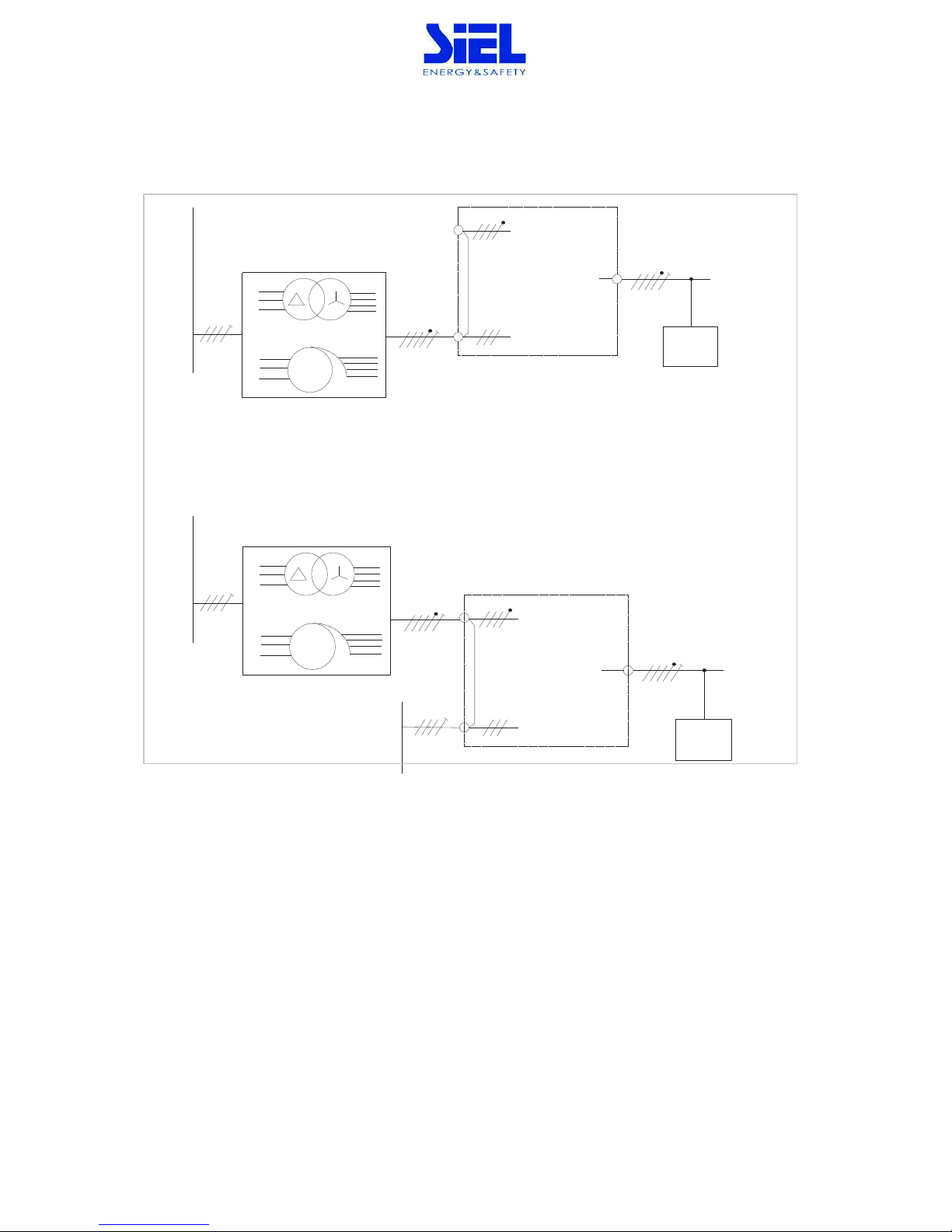
Battery connections
BATTERY CABINET if present:
For connection to the UPS, the battery cabinet must have an overcurrent protection device and
a disconnecting device.
This
disconnector must be closed only when the UPS is started up regularly. During
connection
to the UPS the disconnector must stay in the open position.
Up to 3 battery cabinets can be connected in parallel,
in accordance with the diagram below.
UPS
-
Battery cabinet
+
Battery cabinet
SWBAT2
-
max 3 battery cabinet
+
SWBAT3
-
+
 Loading...