

Siegenia Drive Series, MSA400 smart Installation And Operating Instructions Manual
DRIVE
Motorised Sliding System.
MSA400 smart
INSTALLATION AND
OPERATING INSTRUCTIONS
Window systems
Door systems
Comfort systems
MSA400 smart Installation and operating instructions
Contents
1. General information ................................................................................................................................................................... 3
2. Safety notes ................................................................................................................................................................................ 4
3. Device functions .......................................................................................................................................................................... 5
4. Size range ................................................................................................................................................................................... 7
5. Scope of delivery ........................................................................................................................................................................ 7
6. On-site risk and hazard analysis ................................................................................................................................................ 8
7. Installation ................................................................................................................................................................................... 9
8. Commissioning .........................................................................................................................................................................18
9. Operation .................................................................................................................................................................................20
10. Programming special functions ..............................................................................................................................................22
11. Reset the sash position ...........................................................................................................................................................22
12. Care and maintenance ..........................................................................................................................................................23
13. Rectification of malfunctions ..................................................................................................................................................24
14. Technical specifications ..........................................................................................................................................................25
15. Accessories ............................................................................................................................................................................. 25
16. Information concerning product liability ...............................................................................................................................26
17. Feedback on documentation ................................................................................................................................................. 26
18. EC declaration of incorporation ............................................................................................................................................27
2
05.2017
Installation and operating instructions MSA400 smart
1. General information
Please read these installation and operating instructions carefully and in full before commissioning
the MSA400 smart sliding system.
1.1 Target group of this documentation
• This documentation is intended for use by specialists and end users.
• All instructions concerning installation, commissioning, repairs and maintenance described in this document are to be
performed exclusively by electricians with training and practice in the installation, commissioning and maintenance of
mechanical drives.
• All instructions on operation and maintenance described here are intended for end users.
• Following installation, the installation company must hand over the installation and operating instructions to the end user
and brief the user/owner of the building accordingly.
1.2 Intended use
• The MSA400 smart is an electric motor-driven system for opening and closing windows/patio doors with sliding
hardware (sliding elements). It has a maximum displacement force of 50 N (or 90 N on application of a light curtain)
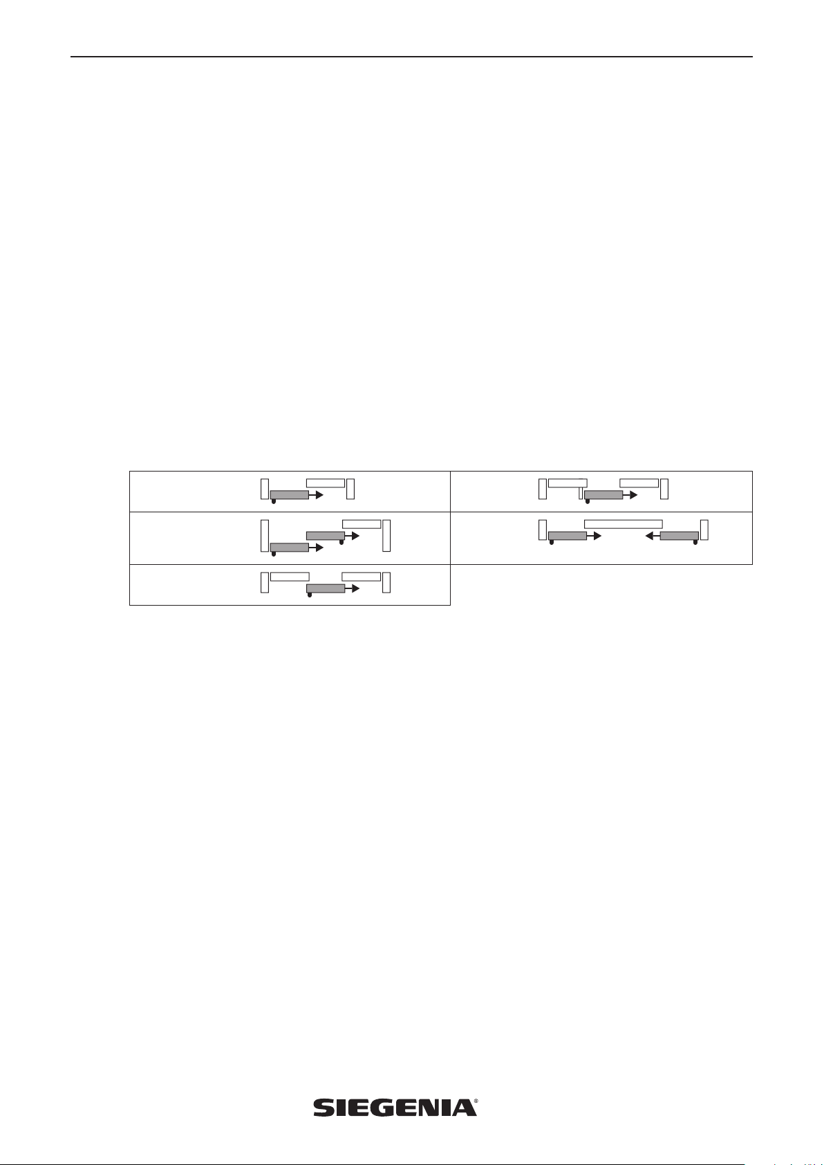
and a travel range of up to 8 m, and it may only be installed in elements which are compatible with these specifications:
Scheme A Scheme G2
Scheme E
max. 250 kg per sash
Scheme G
• The standard MSA400 smart system is not suitable for use in swimming pools and/or damp rooms. Special designs are
possible and permitted only upon request and after having been tested by SIEGENIA.
• The MSA400 smart must only be operated with hardware components and genuine accessories from SIEGENIA.
• It must be possible to access and disassemble the slide drive SA at all times should maintenance and service work be
required (curtain rods, lamps, ceiling covers, roller shutter housings, etc. must not hinder removal).
• The instructions contained in ASR A 1.6, VFF data sheet KB.01 as well as EN 12453 for power-operated windows, doors
and gates must be observed!
• If you are using the system for commercial purposes, you must also observe the safety instructions of your accident
insurance provider.
• Following installation of the MSA400 smart, you must carry out a reference run as well as a calibration and teach-in run
when the unit is commissioned for the first time.
1.3 Incorrect use
Scheme K
• Sliding elements equipped with the MSA400 smart slide system may not be used as escape doors in the event of a fire.
• Any use of this product that is not in accordance with its correct use, or any adaptation of or modification to the product
and its associated components for which the express consent of SIEGENIA has not been obtained, is strictly prohibited.
SIEGENIA accepts no liability whatsoever for any material losses or injury to people caused by failure to comply with this
stipulation.
1.4 Dimensions
• All the dimensions in this documentation are specified in mm.
05.2017 3

MSA400 smart Installation and operating instructions
2. Safety notes
Risk of injury or fatal injury. Hands, arms, legs and feet can get trapped and/or crushed in systems
driven by an electric motor.
• Make sure that no parts of the body or objects are within the shearing and locking area of the system.
• Ensure that no body parts or objects are under the sliding sash, especially when lowering sliding elements.
• This unit can be used by children aged 8 and above as well as by people with physical, sensory or mental difficulties or
with a lack of experience and knowledge as long as they are supervised or have been instructed in how to use the unit
safely and understand the resulting risks. Children must not play with the unit. Cleaning and user maintenance must not be
carried out by children without supervision.
Risk of injury or death due to electrical shock or fire. Systems driven by an electric motor can
overheat and cause fire.
• Insert the Euro mains plug of the standard connecting cable only into a suitable 230VAC mains power supply socket.
• Only a qualified electrician may perform any work on the 230V AC mains power supply.
• Current local regulations (such as VDE 0100 of the VDE in Germany) must be observed.
• Relevant country-specific regulations must be strictly followed for all work on the voltage supply system or building wiring
system.
• All-pole safety isolation is required when the mains cable is laid on-site because the power supply does not have a
separate line disconnector.
• Connect in-wall supply lines to the MSA400 smart sliding system in branch boxes. These branch boxes must be kept
accessible for maintenance.
• When cleaning the sliding sash and the drives, make sure that no liquid gets inside the MSA400 smart system as this
could damage the electronics.
• The unit must be checked by a specialist in the event of a fault.
• Should a solid object or any liquid get inside the unit, stop operation immediately and disconnect the MSA400 smart
system from the mains. Then have the MSA400 smart system checked and repaired by qualified specialists only.
• If the network connection cable is damaged, it may only be replaced by SIEGENIA, its customer service department or
an electrician.
Injuries caused by falling objects.
• Please do not put or place objects on top of the MSA400 smart.
Hazard due to third party attacks on SIEGENIA WLAN devices! Please observe the following notes
to protect your system against attacks by third parties:
• Every SIEGENIA WLAN device is protected by two passwords (user and administrator). It is essential that you change
these passwords after the initial setup. Do not leave in the default setting.
• If the SIEGENIA WLAN devices are integrated in your home WLAN, this must be encrypted for operation.
• Please choose secure passwords consisting of lower case and capital letters, numbers and special symbols.
4
05.2017
Installation and operating instructions MSA400 smart
3. Device functions
3.1 General product description
• The MSA400 smart is a motorised sliding system for the automatic movement of sliding elements
• The MSA400 smart can be controlled by a tablet or smartphone and offers additional device functions via the SIEGENIA
Comfort app. Please follow the enclosed quick start instructions (H47.MOTS005EN).
• The slide drive SA features an electronic cut-off function (see “3.3 Information on safety cut-off and jam protection” on
page 6).
• To further increase safety during travel, the slide drive SA with terminal board allows for the integration of a light curtain.
If an object is placed in the path of the sliding sash, it will be stopped immediately.
• The sliding sash can be moved into a freely programmed intermediate position (intermediate stop).
3.2 Control
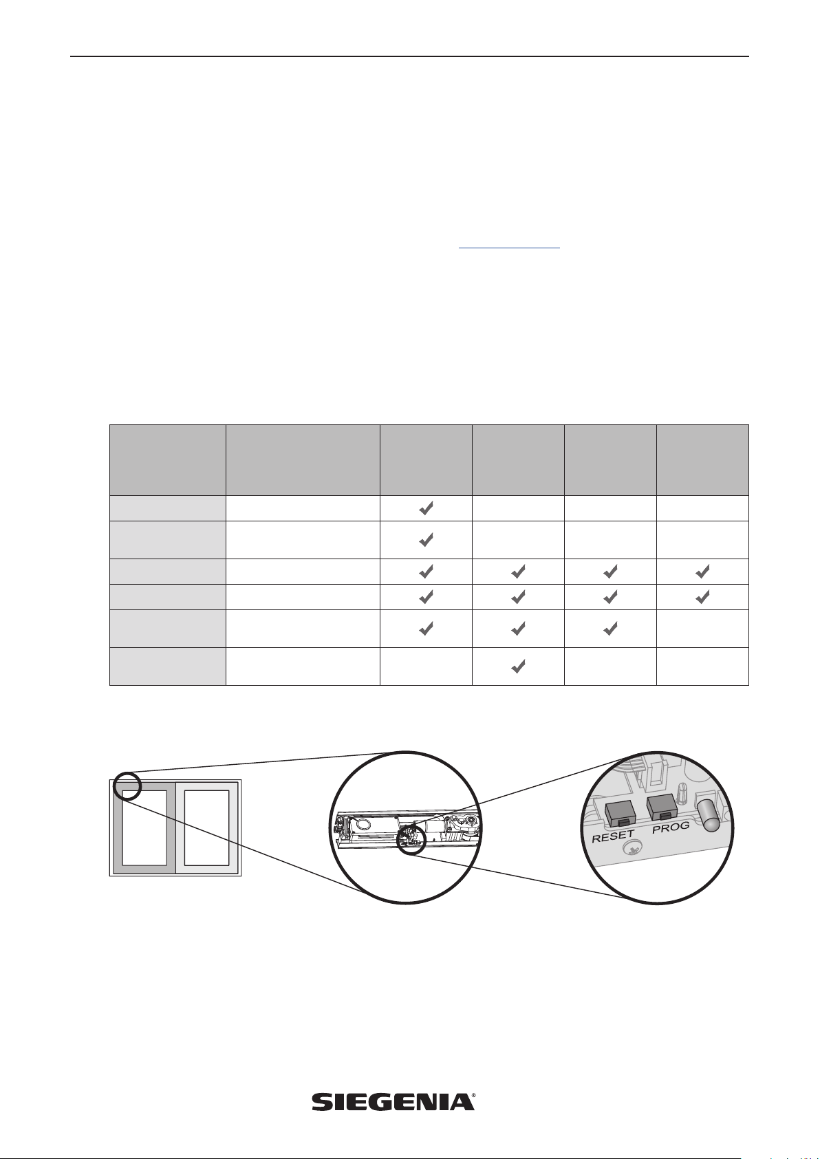
The MSA400 smart system offers the following control options:
Function End position of the
sliding sash
Reference run
Calibration and
teach-in run
Open
Close
Intermediate stop User-defined, limited
Night vent timer
(0‒60 min.)
Button on the MSA400 smart
The Reset and Prog buttons are used to reset the sash position and to program the system.
Closed
Closed
Open
Closed
opening width
Night vent position — — —
Button on the
MSA400 smart
SIEGENIA
Comfort app
— — —
— — —
Infrared remote
control
(optional
accessory)
On-site button
—
05.2017 5
MSA400 smart Installation and operating instructions
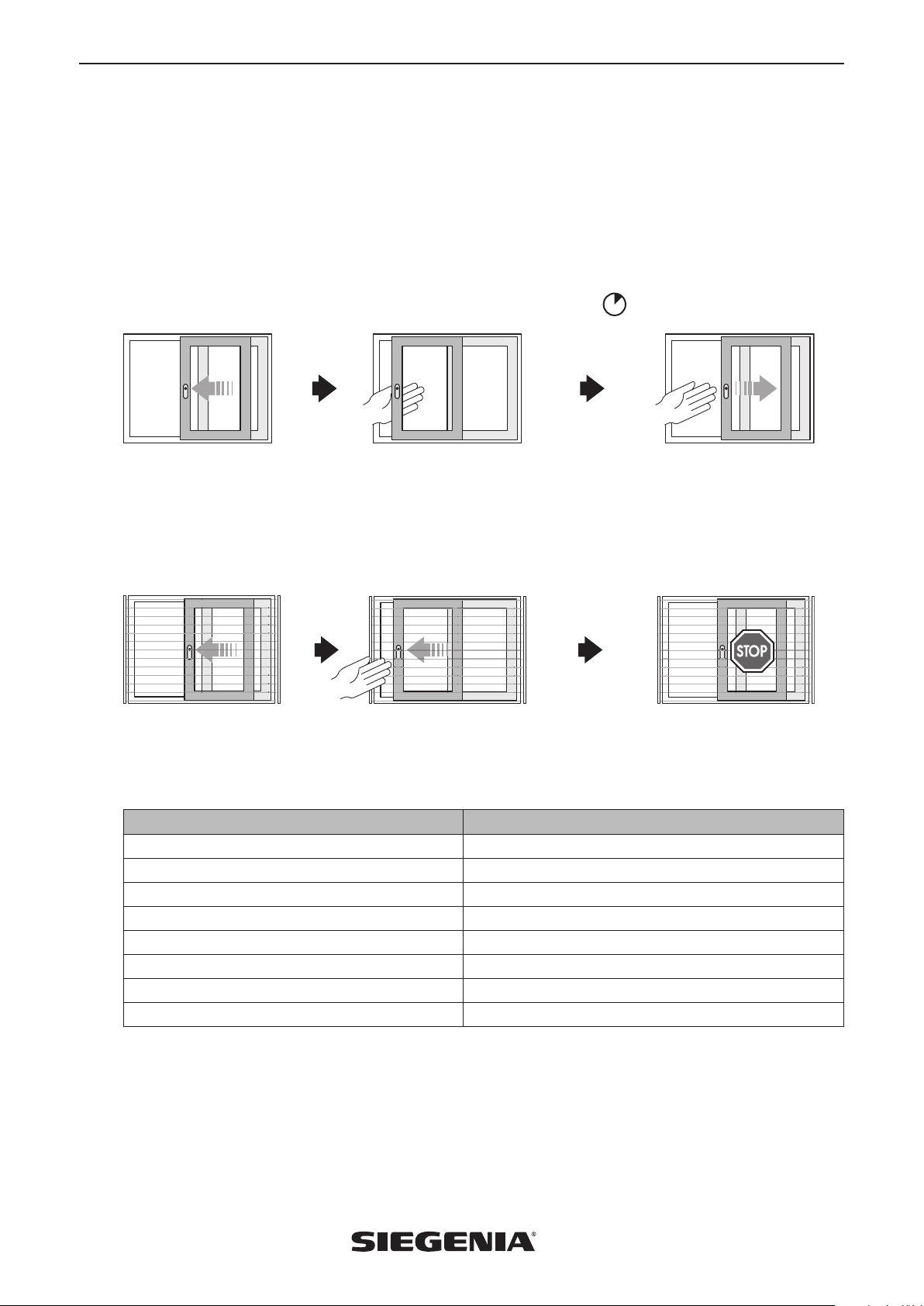
3.3 Information on safety cut-off and jam protection
General information on safety cut-off
As soon as the slide path of a sliding sash becomes blocked (e.g. due to an obstacle or because it is stuck), it stops, moves for
approx. 4 seconds in the opposite direction and then comes to a final stop (see figure below).
For increased safety in the area around the bottom shear points between the sliding sash and the sliding sash frame, in
normal motor-powered operation, the sliding sash only moves as far as a defined opening position.
Sliding sash moves ... ... hits an obstacle and stops... ... then moves for approx. 4 seconds
in the opposite direction and stops
Safety shutdown in systems with light curtain
If additional safety requirements apply, the optional terminal board must be ordered. Also available prepared to be
equipped with a light curtain. To prevent injuries and damage, the safety cut-off function is performed, which brings the
sliding sash to an immediate standstill. If equipped with a light curtain, the sliding sash is opened to its full extent.
Sliding sash moves ... ... an object moves into the safety zone... Sliding sash stops
3.4 LED indicator
The LED is attached to the lower edge of the slide drive SA. Please note the light indicators in the LED. The indicators and their
meanings are listed in the table below:
Function and meaning LED
System test or overheating Flashes red/green in alternation
Teach in Flashes red
Move in direction of "Open" position Continuously green
Move in direction of "Close/Lock" position Continuously red
10-min. night vent (timer running) Flashes green
Intermediate stop (limited opening width) Off
Locked Off
After a power failure Flashes red
6
05.2017
Installation and operating instructions MSA400 smart
1
2
3
4
5
6
8 9
10
7
11
DRIVE
Fenstersysteme
Türsysteme
Komfortsysteme
MSA 400 smart
4. Size range
The MSA400 smart system is installed horizontally on the inside top of the sliding element frame.
Traverse path 8,000 mm
Displacement force 50 N
Displacement force with light curtain installed 90 N
Max. permissible sash weight for MSA400 smart Max. 400 kg (2 x 250 kg scheme E)
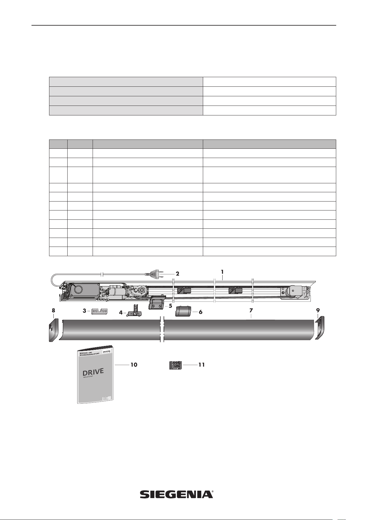
5. Scope of delivery
Pos. Pieces Designation Version
1 slide drive SA Including 24 V power supply
1
1 Network connection cable with Euro plug On slide drive SA, 5 m cable length, for 230 V AC
2
1 Packer (2.5, 5, 8 or 10 mm thick depending
3
on profile system)*
1 Catch base for sliding sash top
4
1 Catch (profile-dependent adapter) On slide drive SA
5
1 Cover cap For catch
6
1 Cover profile SA* For slide drive SA
7
1 Cover cap SA left* For cover profile SA
8
1 Cover cap SA right* For cover profile SA
9
1 Installation and operating instructions
10
1 Terminal board* For connecting light curtain
11
*optional, not included in the standard scope of delivery
for catch on sliding sash
05.2017 7

MSA400 smart Installation and operating instructions
6. On-site risk and hazard analysis
In order to assess the potential hazards of a power-operated window and to take the appropriate protective measures, you
must assess risks in the planning phase. A risk analysis provides you with all the information needed to assess risks and make
decisions concerning the safety of the window elements. The sliding element of the MSA400 smart can cause crushing and
shearing. You must carry out a risk and hazard analysis during the planning phase in accordance with VFF data sheet KB.01
and the current Machinery Directive relating to the safety equipment and installation location as appropriate for the
individual property and conditions of use (e.g. in case of persons requiring special protection or commercial properties).
6.1 Risk and hazard analysis
• Takes into account the protective measures necessary in the planning phase
• Must be carried out before commissioning
• Provides information based on the individual installation location and instructs users on how to install the window system
in order to prevent or minimise possible hazards
• Draws attention to possible residual risks
The following aspects must be checked:
• Public or non-public area (private or industrial property)
• Installation location
• Users (authorised users, persons in need of protection or trained personnel)
• Special structural conditions
• Type of access control
• Requirements for added safety can be met with a light curtain
6.2 Instructions for assembly and installation
• Use flexible supply lines (route conduit tubes if necessary)
• When routing cables, avoid damaging the cables by crushing, bending or stretching them
• The concealed mains supply lines running to the MSA400 smart must be connected in branch boxes (these branch boxes
must be easily accessible for maintenance)
• Protect the MSA400 smart system against contamination by site material and humidity
• The hardware components must be securely fixed in place
• Connect to the mains supply only after you have tested for proper mechanical function
• Observe the applicable fabrication guidelines from the profile manufacturer
• To avoid personal injury, it is important to observe the safety precautions provided in these instructions and make sure
that these instructions are accessible at all times
6.3 Cooperation between trades and interfaces
In the context of project management, the work of the various trades must be carefully coordinated. If SIEGENIA components
are being connected to third-party installations or SIEGENIA products are being combined with parts by other manufacturers
(e.g. drives and controls), technical compatibility must be verified in advance by authorised personnel. For data collation
purposes, the technical data sheets and the latest versions of the installation and operating instructions must be handed over
to the trades involved when work commences.
8
05.2017
Installation and operating instructions MSA400 smart
1
2
3
4
7. Installation
7.1 Installation requirements
General information about installation
• The following description of the assembly process is a recommendation from SIEGENIA and describes the major steps
involved. The specific details of the assembly process are determined, amongst other factors, by the sliding element used,
by the production process and by the window manufacturer's equipment and facilities.
• You will find specific steps for installation of the MSA400 smart on our download portal:
downloads.siegenia.com/de/00007/index.html
Risk of mechanical defects if the MSA400 smart system is put into operation
unassembled.
› You must assemble the MSA400 smart first before putting it into operation!
Sliding element requirements
• The sliding element must not be warped.
• The sliding element must be installed vertically plumb in the reveal.
• The threshold must be properly and sufficiently supported — especially with wide or heavy sliding elements (e.g. 400 kg).
• The displacement force must not be > 60 N.
• The cable routing of the cable in the sliding sash must be checked prior to assembly. The sliding sash must be prepared
for an optimum cable channel in the eurogroove.
• The concealed mains cable guide must be located on the horizontal top section of the frame near the locking side.
Requirements to be met by the hardware
• The hardware must be able to run smoothly (be in unrestricted working order).
Requirements to be met by the drive
Risk of mechanical defects if the MSA400 smart system is put into operation with
sliding elements which cannot move freely.
› Only put MSA400 smart into operation if the smooth running of the sliding element can be ensured!
• The MSA400 smart system has not been tested as a locking unit in accordance with ENV 1627-1630.
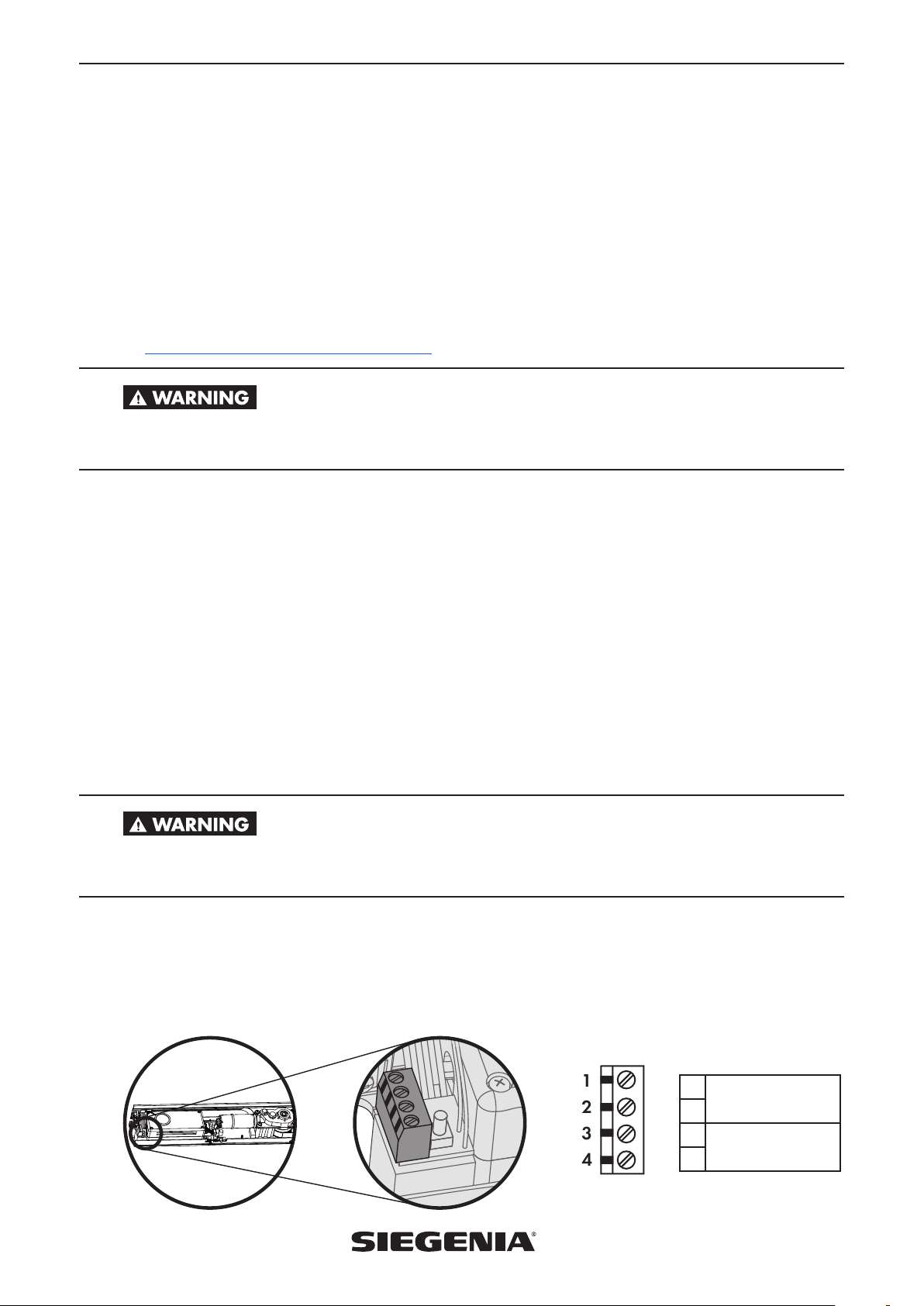
7.2 The connection of external operator push buttons and locking motor (not included in scope of delivery)
• You can also connect an optional external operator push button and a locking motor to the MSA400 smart system,
maximum connection 24V DC 1A.
1
Locking motor
2
3
Operating push
button
4
05.2017 9
 Loading...