

Siegenia KVF Genius Assembly Instructions Manual

WINDOW HARDWARE
DOOR HARDWARE
SLIDING DOOR HARDWARE
VENTILATION TECHNOLOGY
BUILDING TECHNOLOGY
DOOR HARDWARE
GENIUS
Elektronic door lock
Assembly Instructions


1
Last update: 01.08.2013
Assembly instructions
GENIUS
Contents
Target group of this documentation.............................................................. 2
Intended use................................................................................................ 2
Improper use............................................................................................... 2
Safety notes................................................................................................. 2
Explanation of symbols............................................................................... 3
Rotary switch (optional signal outputs)......................................................... 3
Installation.................................................................................................. 4
GENIUS door lock connections...................................................................... 5
Cable links.................................................................................................. 7
Fitting the door contact................................................................................. 8
Fitting an internal release push-button (optional).......................................... 9
Fitting the infra-red eye (optional)................................................................. 9
Wiring diagram for type A GENIUS door lock................................................10
Wiring diagram for type B GENIUS door lock.................................................11
Technical specifications..................................................................................12
Liability.........................................................................................................12

2
Last update: 01.08.2013
GENIUS
Assembly instructions
Target group of this documentation
This documentation is intended to be used by specialists only. All work described in this document is to be performed by
experienced professionals with training and practice in the assembly, installation and maintenance of the GENIUS door
lock and its individual components. Safe and proper assembly of this electronic door lock is not possible without expert
knowledge.
Intended use
• The GENIUS door lock is a special lock for automatically locking and unlocking doors.
• It is suitable for installation in timber, aluminium, steel and PVC entry doors for residential and public buildings.
• All assembly and electrical installation work must be carried out according to our assembly and installation instruc-
tions. Wiring the unit incorrectly can irreparably damage its electronic components.
• The GENIUS door lock must be used with a free-running cylinder compliant with the German standard DIN 18252.
Alternatively a thumbturn cylinder can be used, but it should be noted that this will result in a loss of power at the
locking points.
• The GENIUS door lock can be connected to an external access control system (e.g. wireless, transponder or fingerprint scanner system) via a voltage-free contact (switching time: min. 1 second).
• Use the GENIUS door lock only when it is in a technically sound condition. Do not modify the unit's components in
any way.
• Use the GENIUS door lock only with genuine KFV accessories.
Improper use
• The GENIUS door lock must not be used with a cylinder with a fixed catch, as this will cause the main lock to jam
when the key is removed.
• The GENIUS door lock must not be installed in moisture-prone areas or areas with a corrosive atmosphere (e.g. electroplating shops).
• The length of the cable between the power supply and the GENIUS door lock must not exceed 13 m.
Safety notes
• Work on an 230 V AC mains power supply may only be performed by a qualified electrician.
• All work on the 230 V AC mains power supply must be carried out in compliance with the current German VDE regu-
lations (e.g. VDE 0100) and any relevant country-specific requirements.
• All-pole safety isolation should be used when fitting the power lead on-site.
• Some external access control systems available on the market transmit a brief "open" signal when the operating vol-
tage is switched on. This can mean that the GENIUS door lock will open the door following a power cut. If in doubt,
please contact the system manufacturer.
Where power supply cables are routed parallel to data cables (IDSN, DSL etc), interference can occur, eg: with
the data transfer speed.
Warning
3
Last update: 01.08.2013
Assembly instructions
GENIUS
Explanation of symbols
Milling cutter or drill diameter
Groove depth from profile
Groove length
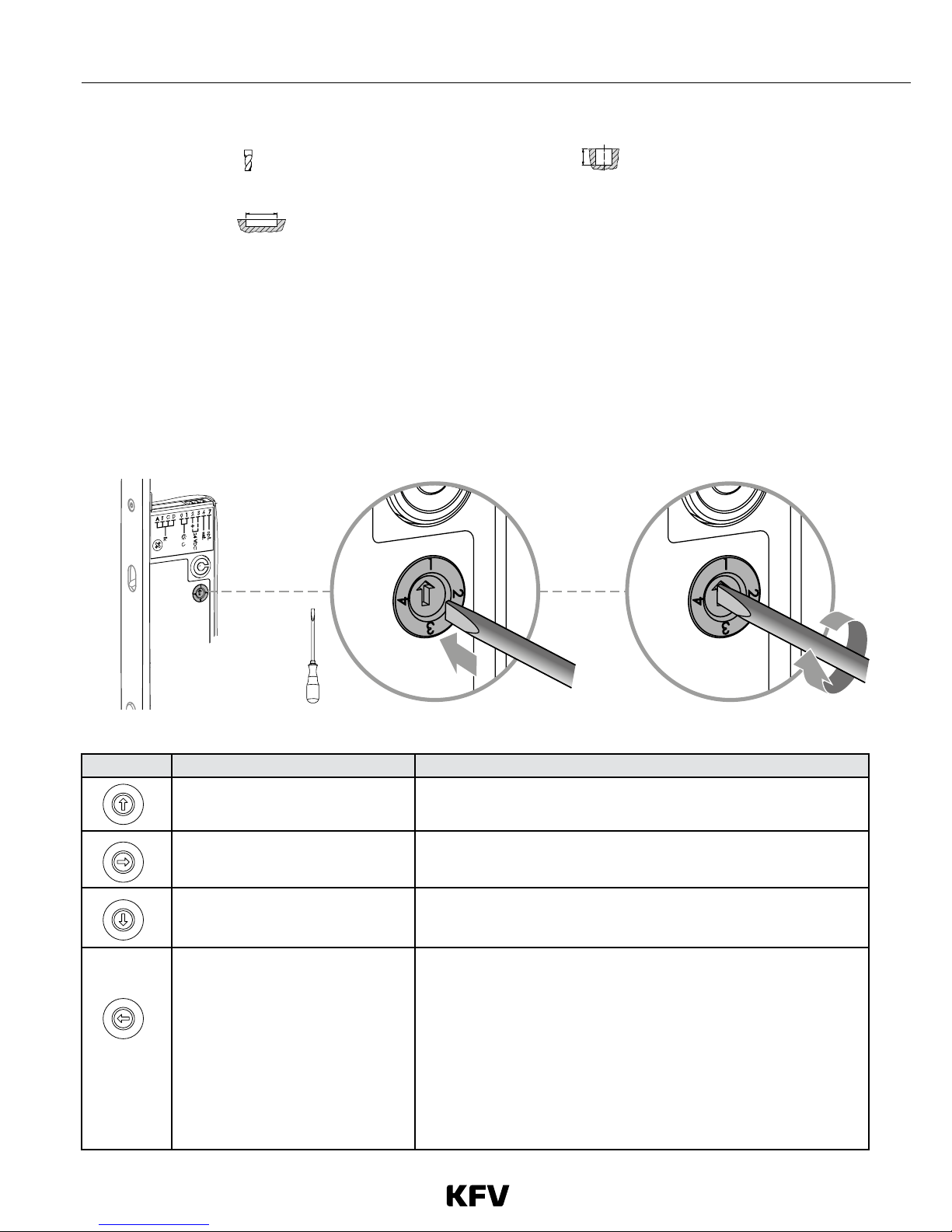
Rotary switch (optional signal outputs)
• The rotary switch can only be operated when the lock is not installed.
• The rotary switch is used to control the optional signal output, terminal 7. The output must not be subjected to a cur-
rent of more than 20 mA.
• The rotary switch on the type B GENIUS door lock is used, if desired, to define the lock or door status that should
trigger the optional signal output.
• Via an external relay (a 24 V DC coupling relay, available as a KFV accessory) connected to terminal 7, the GENIUS
door lock can be linked to other systems, e.g. alarm systems and hinged door drives.
Fig. 1: Rotary switch
Position Status Comments
The lock is fully locked and the door
is shut.
• For use in conjunction with alarm systems.
› Terminal 7 is connected to negative (-) ground.
The door is shut • For use in conjunction with monitoring by a porter.
› Terminal 7 is connected to negative (-) ground.
The latch is drawn into the cylinder
operated lock
• For use in conjunction with a hinged door drive.
› Terminal 7 is connected to negative (-) ground.
Can be used to arm/disarm a connected alarm system
• Controlled using a 2-channel infra-red access key*
• In order to keep the alarm system armed in the event of a power
failure, the terminal is connected to negative/ground when the
alarm is disarmed.
› Alarm disarmed = terminal 7 = negative -- relay on
› Alarm armed = terminal 7 = high resistance -- relay off
• The break contact of the relay must be used to switch on the
alarm system.
*See GENIUS operating instructions for details of how to do this
1
2
3
4
1
2
3
4
1
2
3
4
1
2
3
4
 Loading...