

Siegenia KFV GENIUS 2.1 PANIC Assembly Instructions Manual

KFV
GENIUS 2.1 PANIC
Electro-mechanical systems
ASSEMBLY INSTRUCTIONS

Contents
2
03.2017
KFV
GENIUS 2.1 PANIC
Contents
1. Introduction . . . . . . . . . . . . . . . . . . . . . . . . . . . . . . . . . . . . . . . . . . . . . . . . . . . . . . . . . . . . . . . . . . . . . . . . . . . . 4
1.1 Validity . . . . . . . . . . . . . . . . . . . . . . . . . . . . . . . . . . . . . . . . . . . . . . . . . . . . . . . . . . . . . . . . . . . . . . . . . . . . . . . 4
1.2 Target group of this documentation . . . . . . . . . . . . . . . . . . . . . . . . . . . . . . . . . . . . . . . . . . . . . . . . . . . . . . . . . . 4
1.3 Correct use . . . . . . . . . . . . . . . . . . . . . . . . . . . . . . . . . . . . . . . . . . . . . . . . . . . . . . . . . . . . . . . . . . . . . . . . . . . . 4
1.3.1 Multi-point lock . . . . . . . . . . . . . . . . . . . . . . . . . . . . . . . . . . . . . . . . . . . . . . . . . . . . . . . . . . . . . . . . . . . . . . . . . 4
1.4 Improper use . . . . . . . . . . . . . . . . . . . . . . . . . . . . . . . . . . . . . . . . . . . . . . . . . . . . . . . . . . . . . . . . . . . . . . . . . . . 4
1.5 Installation location . . . . . . . . . . . . . . . . . . . . . . . . . . . . . . . . . . . . . . . . . . . . . . . . . . . . . . . . . . . . . . . . . . . . . . 5
1.6 Transport . . . . . . . . . . . . . . . . . . . . . . . . . . . . . . . . . . . . . . . . . . . . . . . . . . . . . . . . . . . . . . . . . . . . . . . . . . . . . . 5
1.7 Installation conditions and requirements . . . . . . . . . . . . . . . . . . . . . . . . . . . . . . . . . . . . . . . . . . . . . . . . . . . . . . 5
1.8 Maintenance and service notes. . . . . . . . . . . . . . . . . . . . . . . . . . . . . . . . . . . . . . . . . . . . . . . . . . . . . . . . . . . . . 6
1.9 Dimensions . . . . . . . . . . . . . . . . . . . . . . . . . . . . . . . . . . . . . . . . . . . . . . . . . . . . . . . . . . . . . . . . . . . . . . . . . . . . 6
1.10 Visual indicators . . . . . . . . . . . . . . . . . . . . . . . . . . . . . . . . . . . . . . . . . . . . . . . . . . . . . . . . . . . . . . . . . . . . . . . . 6
1.10.1 Instructions and symbols . . . . . . . . . . . . . . . . . . . . . . . . . . . . . . . . . . . . . . . . . . . . . . . . . . . . . . . . . . . . . . . . . . 6
1.11 Explanation of symbols . . . . . . . . . . . . . . . . . . . . . . . . . . . . . . . . . . . . . . . . . . . . . . . . . . . . . . . . . . . . . . . . . . . 6
1.12 Other types of indicators . . . . . . . . . . . . . . . . . . . . . . . . . . . . . . . . . . . . . . . . . . . . . . . . . . . . . . . . . . . . . . . . . . 6
1.13 Screw recommendation. . . . . . . . . . . . . . . . . . . . . . . . . . . . . . . . . . . . . . . . . . . . . . . . . . . . . . . . . . . . . . . . . . . 6
1.14 Causes of damage . . . . . . . . . . . . . . . . . . . . . . . . . . . . . . . . . . . . . . . . . . . . . . . . . . . . . . . . . . . . . . . . . . . . . . 7
2. Safety . . . . . . . . . . . . . . . . . . . . . . . . . . . . . . . . . . . . . . . . . . . . . . . . . . . . . . . . . . . . . . . . . . . . . . . . . . . . . . . . 8
2.1 Personal protective equipment. . . . . . . . . . . . . . . . . . . . . . . . . . . . . . . . . . . . . . . . . . . . . . . . . . . . . . . . . . . . . . 8
2.2 Heavy components . . . . . . . . . . . . . . . . . . . . . . . . . . . . . . . . . . . . . . . . . . . . . . . . . . . . . . . . . . . . . . . . . . . . . . 8
2.3 Sharp edges . . . . . . . . . . . . . . . . . . . . . . . . . . . . . . . . . . . . . . . . . . . . . . . . . . . . . . . . . . . . . . . . . . . . . . . . . . . 8
2.4 Swarf flying around rapidly. . . . . . . . . . . . . . . . . . . . . . . . . . . . . . . . . . . . . . . . . . . . . . . . . . . . . . . . . . . . . . . . 8
2.5 Electric voltage . . . . . . . . . . . . . . . . . . . . . . . . . . . . . . . . . . . . . . . . . . . . . . . . . . . . . . . . . . . . . . . . . . . . . . . . . 8
3. Assembly of sash side . . . . . . . . . . . . . . . . . . . . . . . . . . . . . . . . . . . . . . . . . . . . . . . . . . . . . . . . . . . . . . . . . . . . 9
3.1 Delivery options. . . . . . . . . . . . . . . . . . . . . . . . . . . . . . . . . . . . . . . . . . . . . . . . . . . . . . . . . . . . . . . . . . . . . . . . . 9
3.2 Component dimensions . . . . . . . . . . . . . . . . . . . . . . . . . . . . . . . . . . . . . . . . . . . . . . . . . . . . . . . . . . . . . . . . . .10
3.3 Cutting the door leaf . . . . . . . . . . . . . . . . . . . . . . . . . . . . . . . . . . . . . . . . . . . . . . . . . . . . . . . . . . . . . . . . . . . . 11
3.4 Main locks and auxiliary boxes. . . . . . . . . . . . . . . . . . . . . . . . . . . . . . . . . . . . . . . . . . . . . . . . . . . . . . . . . . . . 12
3.5 Change DIN orientation of the latches . . . . . . . . . . . . . . . . . . . . . . . . . . . . . . . . . . . . . . . . . . . . . . . . . . . . . . 14
3.6 GENIUS 2.1 PANIC . . . . . . . . . . . . . . . . . . . . . . . . . . . . . . . . . . . . . . . . . . . . . . . . . . . . . . . . . . . . . . . . . . . .15
3.7 Wiring diagram GENIUS 2.1 PANIC . . . . . . . . . . . . . . . . . . . . . . . . . . . . . . . . . . . . . . . . . . . . . . . . . . . . . . .16
3.8 Wiring allocation. . . . . . . . . . . . . . . . . . . . . . . . . . . . . . . . . . . . . . . . . . . . . . . . . . . . . . . . . . . . . . . . . . . . . . . 17
3.9 Establish plug connections GENIUS 2.1 PANIC . . . . . . . . . . . . . . . . . . . . . . . . . . . . . . . . . . . . . . . . . . . . . . . 17
3.10 Screwing on the multi-point lock . . . . . . . . . . . . . . . . . . . . . . . . . . . . . . . . . . . . . . . . . . . . . . . . . . . . . . . . . . . 18
4. Frame side assembly . . . . . . . . . . . . . . . . . . . . . . . . . . . . . . . . . . . . . . . . . . . . . . . . . . . . . . . . . . . . . . . . . . . .19
4.1 Milling the door frame. . . . . . . . . . . . . . . . . . . . . . . . . . . . . . . . . . . . . . . . . . . . . . . . . . . . . . . . . . . . . . . . . . . 19
4.2 Assembling the frame parts and magnet . . . . . . . . . . . . . . . . . . . . . . . . . . . . . . . . . . . . . . . . . . . . . . . . . . . . . 20
4.2.1 The different magnet types . . . . . . . . . . . . . . . . . . . . . . . . . . . . . . . . . . . . . . . . . . . . . . . . . . . . . . . . . . . . . . . 20
4.2.2 Mounting the striker plates in aluminium and PVC frames . . . . . . . . . . . . . . . . . . . . . . . . . . . . . . . . . . . . . . . . 21

Contents
303.2017
KFV
GENIUS 2.1 PANIC
4.2.3 Mounting the striker plates in timber frames . . . . . . . . . . . . . . . . . . . . . . . . . . . . . . . . . . . . . . . . . . . . . . . . . . 22
4.2.4 Mounting the locking rail. . . . . . . . . . . . . . . . . . . . . . . . . . . . . . . . . . . . . . . . . . . . . . . . . . . . . . . . . . . . . . . . . 23
4.3 Adjustment of airgap . . . . . . . . . . . . . . . . . . . . . . . . . . . . . . . . . . . . . . . . . . . . . . . . . . . . . . . . . . . . . . . . . . . . 24
4.4 Adjustment of frame parts and AT piece . . . . . . . . . . . . . . . . . . . . . . . . . . . . . . . . . . . . . . . . . . . . . . . . . . . . . 25
4.4.5 Correct the Q adjustment . . . . . . . . . . . . . . . . . . . . . . . . . . . . . . . . . . . . . . . . . . . . . . . . . . . . . . . . . . . . . . . . 25
4.4.6 Adjustment of AT-piece . . . . . . . . . . . . . . . . . . . . . . . . . . . . . . . . . . . . . . . . . . . . . . . . . . . . . . . . . . . . . . . . . . 26
5. Functional test . . . . . . . . . . . . . . . . . . . . . . . . . . . . . . . . . . . . . . . . . . . . . . . . . . . . . . . . . . . . . . . . . . . . . . . . . 27
5.1 Functional test when the door is open . . . . . . . . . . . . . . . . . . . . . . . . . . . . . . . . . . . . . . . . . . . . . . . . . . . . . . . 28
5.1.1 Testing the panic function (cylinder operated lock E / switching function B) . . . . . . . . . . . . . . . . . . . . . . . . . . 28
5.1.2 Testing the profile cylinder (cylinder operated lock E / switching function B) . . . . . . . . . . . . . . . . . . . . . . . . . 28
5.2 Electromechanical test . . . . . . . . . . . . . . . . . . . . . . . . . . . . . . . . . . . . . . . . . . . . . . . . . . . . . . . . . . . . . . . . . . . 28
5.2.3 Testing the panic function (cylinder operated lock E / switching function B) . . . . . . . . . . . . . . . . . . . . . . . . . . 28
5.2.4 Testing the function of the profile cylinder . . . . . . . . . . . . . . . . . . . . . . . . . . . . . . . . . . . . . . . . . . . . . . . . . . . . 29
5.2.5 Testing the function of the optional access control system . . . . . . . . . . . . . . . . . . . . . . . . . . . . . . . . . . . . . . . . 29
5.3 Troubleshooting. . . . . . . . . . . . . . . . . . . . . . . . . . . . . . . . . . . . . . . . . . . . . . . . . . . . . . . . . . . . . . . . . . . . . . . . 29
5.3.6 Functional disorder of the lever handle/ push bar. . . . . . . . . . . . . . . . . . . . . . . . . . . . . . . . . . . . . . . . . . . . . . 29
5.3.7 Functional disorder of the profile cylinder . . . . . . . . . . . . . . . . . . . . . . . . . . . . . . . . . . . . . . . . . . . . . . . . . . . . 29
5.3.8 Functional disorder of the magnetic field sensor . . . . . . . . . . . . . . . . . . . . . . . . . . . . . . . . . . . . . . . . . . . . . . . 30
5.3.9 Functional disorder due to block movement. . . . . . . . . . . . . . . . . . . . . . . . . . . . . . . . . . . . . . . . . . . . . . . . . . . 30
5.4 Manual adjustment of the magnetic sensor . . . . . . . . . . . . . . . . . . . . . . . . . . . . . . . . . . . . . . . . . . . . . . . . . . . 30
6. Appendix. . . . . . . . . . . . . . . . . . . . . . . . . . . . . . . . . . . . . . . . . . . . . . . . . . . . . . . . . . . . . . . . . . . . . . . . . . . . . 31
6.1 Technical specifications . . . . . . . . . . . . . . . . . . . . . . . . . . . . . . . . . . . . . . . . . . . . . . . . . . . . . . . . . . . . . . . . . . 31
6.2 Liability . . . . . . . . . . . . . . . . . . . . . . . . . . . . . . . . . . . . . . . . . . . . . . . . . . . . . . . . . . . . . . . . . . . . . . . . . . . . . . 32
6.2.1 Intended use . . . . . . . . . . . . . . . . . . . . . . . . . . . . . . . . . . . . . . . . . . . . . . . . . . . . . . . . . . . . . . . . . . . . . . . . . . 32
6.2.2 Product liability . . . . . . . . . . . . . . . . . . . . . . . . . . . . . . . . . . . . . . . . . . . . . . . . . . . . . . . . . . . . . . . . . . . . . . . . 32
6.2.3 Disclaimer of liability . . . . . . . . . . . . . . . . . . . . . . . . . . . . . . . . . . . . . . . . . . . . . . . . . . . . . . . . . . . . . . . . . . . . 32
Introduction
Assembly instructions GENIUS 2.1 PANIC
4
03.2017
KFV
1. Introduction
Please read these assembly instructions carefully before you
begin the assembly work. Follow the instructions in Chapter2
"Safety", in order to prevent personal injury or disturbance.
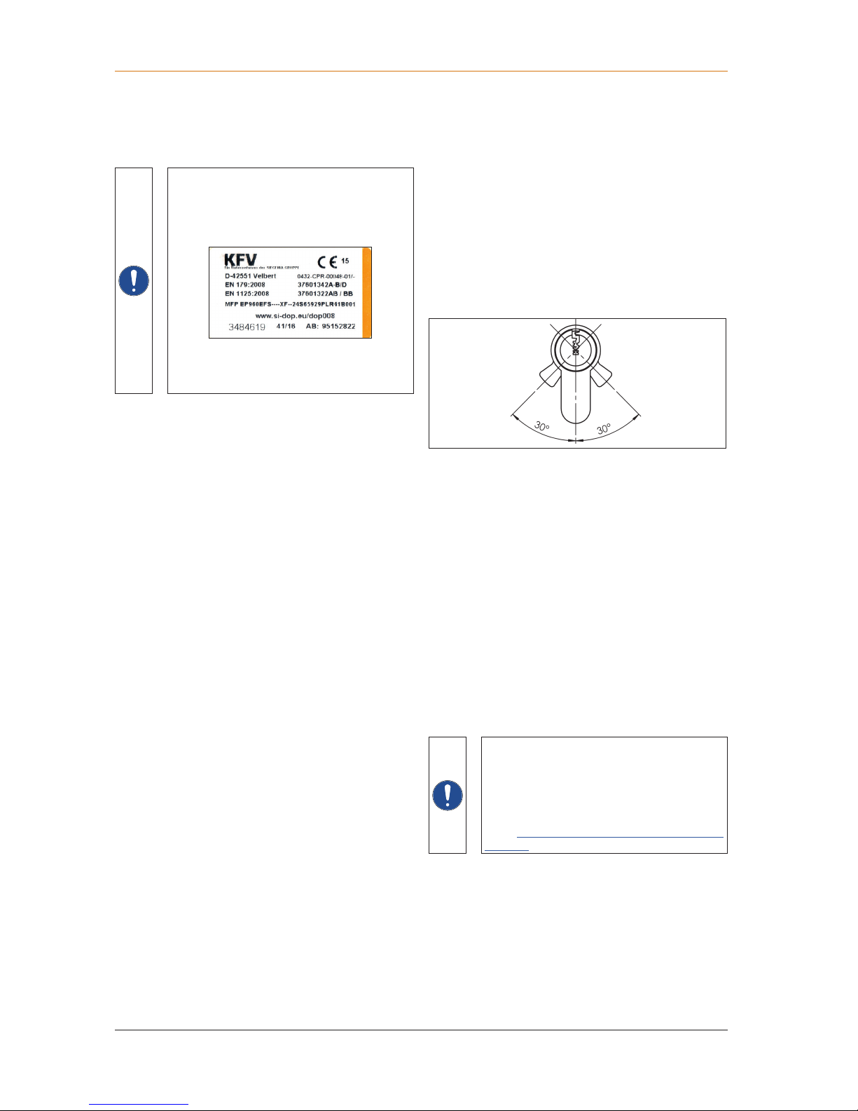
The Quick Reference GENIUS 2.1 PANIC,
enclosed in the product, must be handed over to
the end user.
Keep a copy of the cover side with the attached
sticker in a safe place.
If any additional documents are provided to the end
user, the contents of the provided KFV documentation
must be taken into consideration.
1.1 Validity
These instructions describe the operation of the GENIUS 2.1
PANIC multi-point lock and are valid unless revoked.
1.2 Target group of this documentation
This documentation is intended for use by specialists only.
All work described in this document is to only be performed
by experienced professionals with training and practice
in the installation, commissioning and maintenance of the
GENIUS 2.1 PANIC multi-point lock and its individual
components. Safe and proper assembly of this electronic
door lock is not possible without expert knowledge.
All work on a 230 V AC mains power supply may only be
performed by a qualified electrician.
1.3 Correct use
The GENIUS 2.1 PANIC multi-point lock is a special lock for
locking and unlocking doors automatically.
The GENIUS 2.1 PANIC multi-point lock can be used as a
panic lock in accordance with EN 1125 (version EP or PE) or
also as an emergency exit lock in accordance with EN 179
(version EP or EE).
• The GENIUS PANIC multi-point lock is a unit consisting of
a multi-point lock with the GENIUS 2.1 drive, the actuating
hardware in accordance with EN 1125 (horizontal
actuating bar) or EN 179 (lever handle) and the frame
parts (striker plates, locking rails, bottom bushing, etc.)
Only mutually tested and certified components may be
installed. Any change of this combination (even a partial
change) is inadmissible.
• Use the GENIUS 2.1 PANIC multi-point lock only when it
is in a technically sound condition. Do not modify the unit's
components in any way.
• Use the GENIUS 2.1 PANIC multi-point lock only with
genuine KFV accessories.
• When used in fire escape doors or smoke protection
doors, the locks must be used in combination with an
uninterruptible power supply (UPS)!
• The GENIUS 2.1 PANIC multi-point lock is suitable for
installation in timber, aluminium, steel and PVC entry
doors for residential buildings.
• The GENIUS 2.1 PANIC multi-point lock may only be
used:
• with cylinder locks with free-running catches in which the
catch can always be freely turned
• with cylinder locks with rigid catch in which the catch
is locked in a key withdrawal position inside the
range of -30° to +30°.
• All assembly and electrical installation work must be
carried out according to our assembly and installation
instructions by a qualified electrician. Wiring the unit
incorrectly can irreparably damage its electronic
components.
1.3.1 Multi-point lock
• Only KFV frame parts with Q adjustment may be used.
• Repair of the GENIUS 2.1 PANIC multi-point lock is not
permissible. If it is damaged, the GENIUS 2.1 PANIC
multi-point lock must be replaced. The GENIUS 2.1
PANIC multi-point lock must be replaced once it reaches
the service life indicated below.
• Primary sash ("active sash") – 1- and 2-sash doors:
200,000 activations of the operating handle
• GENIUS 2.1 drive
100,000 locking and unlocking actions (motorised)
If energy-carrying cables are routed in parallel
to data cables (ISDN, DSL, etc.), this could lead
to interference e.g. in the speed of the data
transmission.
We recommend that you use the shielded KFV
cable.
See: Product catalogue KFV GENIUS and
A-opener
1.4 Improper use
• The multi-point lock is not designed to accommodate
changes to its shape or seal which arise as a result of
differences in temperature or changes to the building.

Assembly instructions GENIUS 2.1 PANIC
Introduction
503.2017
KFV
• Always use the transport locks matching the respective
airgap (for example distance blocks) to keep the sash in
position during transport.
• If possible, always transport the door element in the
intended installation position so that the resulting reactive
forces will be ablated in accordance with the constructive
design for the intended installation position.
1.7 Installation conditions and requirements
• Local building laws and regulations must be observed
before and during door installation in addition to the
following requirements and conditions:
• Observe the milling dimensions
• Position the frame parts according to the specifications,
observing the horizontal and vertical adjustment
accurately.
• Before installing the multi-point lock, check the dimensional
accuracy of the door and the door frame. The multi-point
lock must not be installed if the door and/or the frame is
warped and/or damaged.
• Install the multi-point lock and accessories according to
our assembly instructions. Use the clamp included in the
delivery for assembly.
• Remove any splinters from the lock mortise after milling.
• Once the lock is installed, do not perform mechanical
work on the door (such as drilling or milling). Do not drill
into or through the main lock under any circumstances.
• Observe the specified positions and sizes when drilling
the holes.
• Follow the hardware manufacturer's instructions when
drilling the holes for the lever handle/hardware.
• Install hardware components and cylinder flush without
overtightening the screws or screwing them in at an angle.
• Fasten handle set by hand only and do not use force
when installing the spindle.
• Adhere to the gap between the secondary sash and the
frame parts:
• in accordance with DIN 18251-3 = 3.5 ±1.5 mm
• Operating elements should not impede each other.
• Check that any existing block setting is packed correctly.
• Surface treatment of the door and door frame must take
place before the multi-point lock is installed. Treating
these surfaces at a later stage can reduce the functional
capacity of the multi-point lock.
• Use only acid-free neutral-cure sealants to prevent
corrosion of components and/or the door.
• Cylinder locks with rigid catch in which the catch is locked
in a key withdrawal position outside the range of -30°
to +30° may not be used. This includes cylinder locks in
which the catch position can be adjusted manually so that
a catch position outside of the range from -30° to +30°
is possible to reach.
• The GENIUS 2.1 PANIC multi-point lock must not be used
in doors for wet rooms or rooms in which the air contains
aggressive or corrosive components.
• Foreign objects and/or materials which impede or
prevent proper use must not be placed within the opening
range, the multi-point lock or the striker plates.
• The GENIUS 2.1 PANIC multi-point lock must not be
interfered with and/or modified.
• Locking elements must not be misused to hold the door
open.
• Movable or adjustable locking pieces (e.g. deadbolt,
latch) must not be painted over.
1.5 Installation location
• The multi-point lock is suitable for installation in singlesash and double-sash doors in permanent buildings.
• The multi-point lock may only be installed in doors that
have been fitted in a technically sound manner.
• The door design must permit use of the multi-point lock.
• All work on the 230 V AC mains power supply must be
carried out in compliance with the current German VDE
regulations (e.g. VDE 0100) and any relevant countryspecific requirements.
• All-pole safety isolation should be used when fitting the
network connection cable on-site.
• The use of any additional devices to keep the door closed
(with the exception of a door closer, motorised door drive,
block lock and escape door monitor) is not permitted.
If an additional system is installed, it must not impede
operation of the door by children, the elderly or infirm.
• Only KFV frame parts with Q adjustment may be used.
• Opening/closing/locking: It must be possible to open and
close the door easily. A protruding latch and /or deadbolt
must not impede the opening of the door.
1.6 Transport
• Always transport the multi-point lock in a vertical position,
whether uninstalled or installed in the door leaf.
• It is essential to handle the multi-point lock with care and
not to expose it to hard impacts.
• Do not carry the door by the lever handle or hardware
when transporting it.
• Considerable reactive forces could be generated as
a result of wobbling movement during transport which
could cause damage or incorrect loading of the installed
components.
Introduction
Assembly instructions GENIUS 2.1 PANIC
6
03.2017
KFV
1.8 Maintenance and service notes
• Monthly testing and maintenance must be carried out in
accordance with DIN EN 179 (Appendix maintenance
instructions) or DIN EN 1125 (Appendix maintenance
instructions). You will find more information on this in
chapter "Maintenance" of the Operating instructions
"Electro-mechanical systems"
• Never use cleaning agents that are aggressive or
contain solvents, as these may damage the surface of the
components.
• Both the contractor and the user must be trained in the
operation and maintenance of the multi-point lock.
1.9 Dimensions
All measurements are given in mm.
1.10 Visual indicators
1.10.1 Instructions and symbols
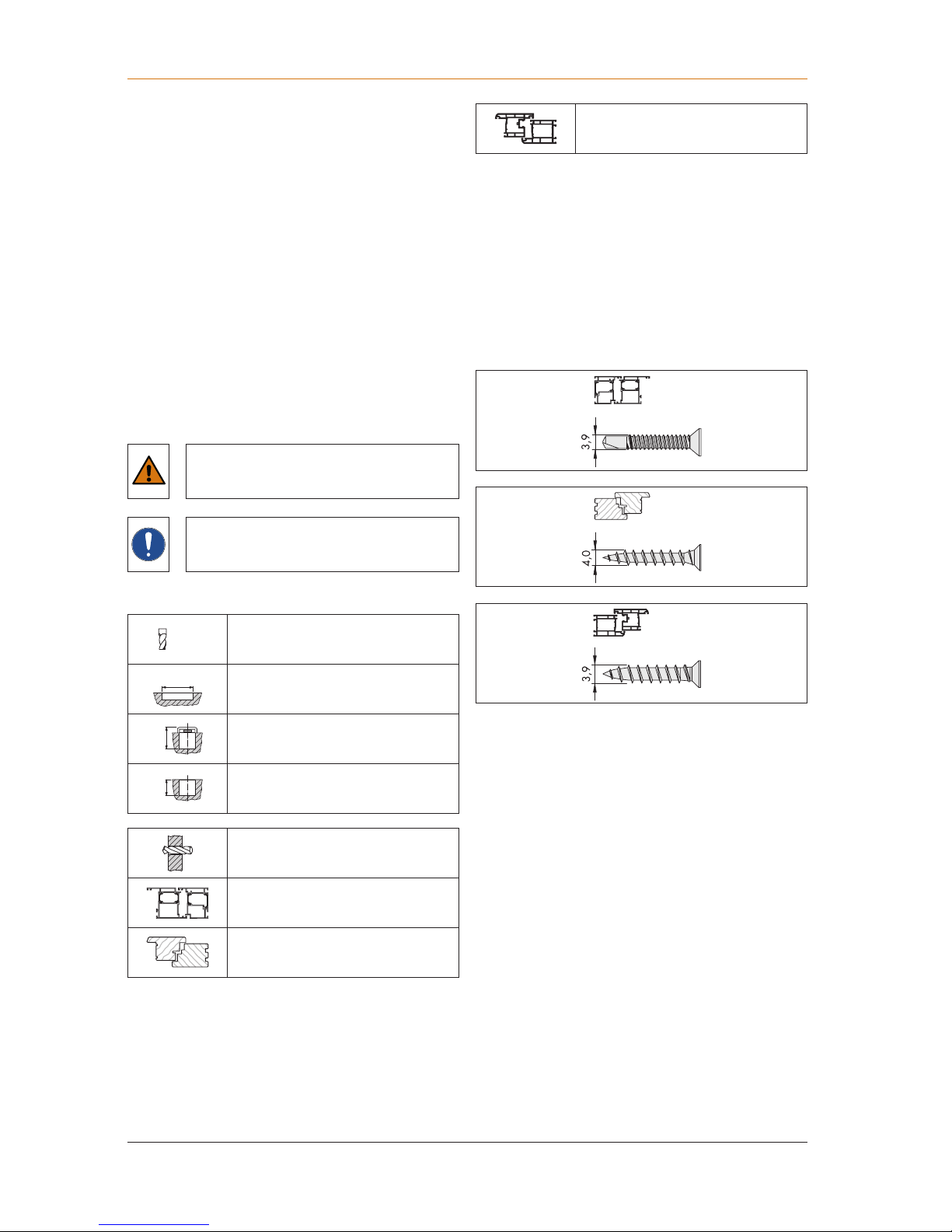
This symbol designates hazards that could
damage the product or something in the
surrounding area.
This symbol indicates special features and
designates facts that require increased
attention.
1.11 Explanation of symbols
Milling cutter or drill diameter
Groove length
Groove depth from component
Groove depth from profile
Through hole
for metal profiles
for timber profiles
for PVC profiles
1.12 Other types of indicators
Below is a list of symbols used in these assembly instructions
and their meanings:
• Items of text following this marker are found in lists.
► Items of text with this marking in front of them are
instructions that must be followed in the specified order.
" " Items of text in quotation marks are cross-references to other
chapters or sections.
1.13 Screw recommendation
Assembly instructions GENIUS 2.1 PANIC
Introduction
703.2017
KFV
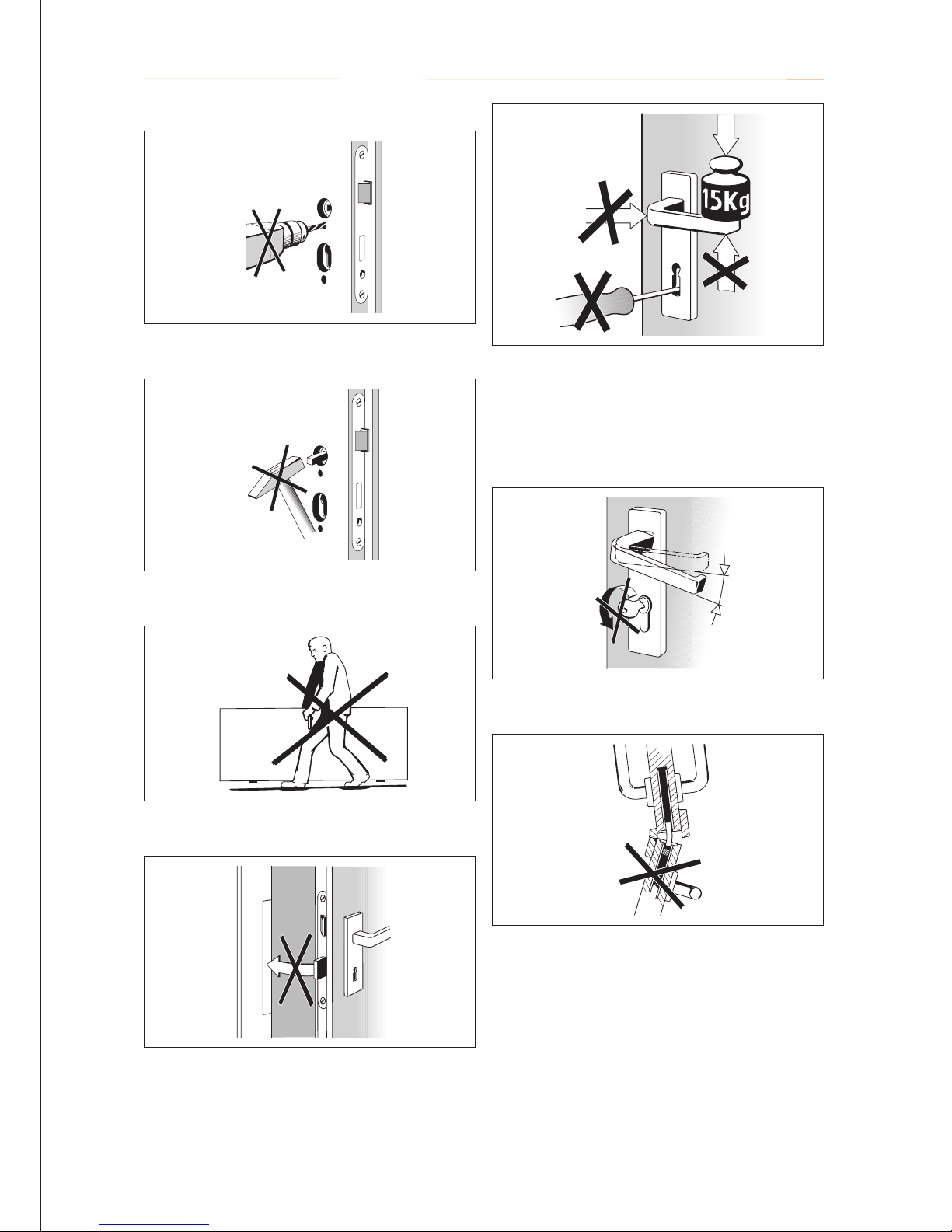
Force must be exerted on the lever handle only in the normal
direction of rotation.
A maximum force of 150 N may be applied to the lever
handle in the direction of actuation.
The lock or multi-point lock must be locked only with the
associated key (and not with foreign objects).
The lever handle and key must not be operated at the same
time.
Double-leaf doors must not be forced open using the
inactive sash.
1.14 Causes of damage
Do not drill through the door leaf in the area of the gear
box/boxes when the lock or the multi-point lock is installed.
The spindle must not be hit through the lock nut with force.
The door leaf must not be carried using the lever handle as
a grip.
None of the locking elements may be excluded when the
door is open.

Safety
Assembly instructions GENIUS 2.1 PANIC
8
03.2017
KFV
2. Safety
Before starting the assembly work, read the following safety
instructions carefully. They are designed to keep you safe
and prevent hazards, injuries and material losses.
2.1 Personal protective equipment
You will need the following protective equipment for the
assembly work:
• Safety shoes
• Protective gloves
• Protective goggles
2.2 Heavy components
Lifting off the door presents a risk of foot injuries.
• Always wear safety shoes.
2.3 Sharp edges
Cropping metal components creates sharp edges. This
presents a risk of cutting injuries.
• Wear suitable protective gloves.
• Deburr the sharp edges.
2.4 Swarf flying around rapidly
During milling work, there will be swarf flying around rapidly.
This presents a risk of eye injuries.
• Wear protective goggles.
2.5 Electric voltage
There is a risk of electric shock during all work on
230VAC mains power supply.
• All work on a 230 V AC mains power supply may only
be performed by a qualified electrician.
• Establish an all-pole safety isolation and secure against
unintentional reconnection before carrying out work on
the 230 V AC mains power supply.

Assembly instructions GENIUS 2.1 PANIC
Assembly of sash side
903.2017
KFV
3. Assembly of sash side
3.1 Delivery options
GENIUS 2.1 PANIC with AS 2600 GENIUS 2.1 PANIC is available in two versions:
Cylinder operated lock E
The door can be completely opened against the direction of
escape with the key or the GENIUS 2.1 PANIC. After using
the escape function, access against the direction of escape
is blocked again once the door closes and it is not possible
to escape back into the building.
Operation:
Emergency opening in the direction of escape: Open door
using the lever handle or horizontal actuating bar.
Locking in Night mode: the door is automatically locked.
Opening against the direction of escape: unlock and open
the door using the key. Turn the key to the unlocking stop.
Locking in Day mode: there is no automatic locking. Lock the
door with the key. Turn the key to the locking stop to lock the
multi-point lock completely.
Switching function B:
Opening the door against the direction of escape using the
lever handle is only possible after unlocking with the key or
by using the motor unlocking via GENIUS. After using the
escape function, access against the direction of escape is
blocked again once the door closes and it is not possible to
escape back into the building.
Operation:
• Emergency opening in the direction of escape: Open
door using the lever handle or horizontal actuating bar.
• Locking in Night mode: the door is automatically locked.
• Manual opening against the direction of escape: unlock
and open the door using the key. Turn the key to the
unlocking stop. Open door using the lever handle or
horizontal actuating bar.
• Timed opening against the direction of escape: GENIUS
via Terminal 0/1 or switch the button to Day mode. Open
door using the lever handle or horizontal actuating bar
• Locking in Day mode: there is no automatic locking. Lock
the door with the key. Turn the key to the locking stop to
lock the multi-point lock completely.
Assembly of sash side
Assembly instructions GENIUS 2.1 PANIC
10
03.2017
KFV
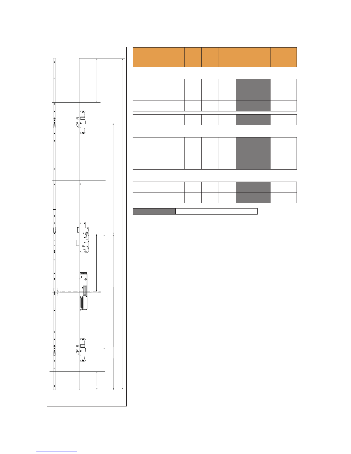
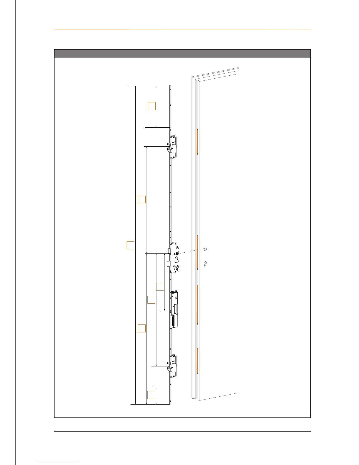
3.2 Component dimensions
I
K
C
B
F
G
A
F + 1 mm
Size
variants
A B C F G I K
suitable for
sash rebate
height
PZ dimension 92
B001 2170 760 730 380
1020 290 130
1881 2170
B002 2170 760 730 380
1050 290 160
1881 2170
B004 2400 760 980 380
1050 270 130
2171 2400
B166 1855 760 730 380
952
1755 2170
PZ dimension 94
B001 2170 760 730 380
1020 290 130
1881 2170
B002 2170 760 730 380
1050 290 160
1881 2170
B004 2400 760 980 380
1050 270 130
2171 2400
PZ dimension 72
B002 2170 760 730 380
1050 290 160
1881 2170
B004 2400 760 980 380
1050 270 130
2171 2400
Dimensions I + K
= can be shortened
Assembly instructions GENIUS 2.1 PANIC
Assembly of sash side
1103.2017
KFV
3.3 Cutting the door leaf
Routed pockets
I
K
C
B
G
A
F
A
G
K
B
F
C
I
Assembly of sash side
Assembly instructions GENIUS 2.1 PANIC
12
03.2017
KFV
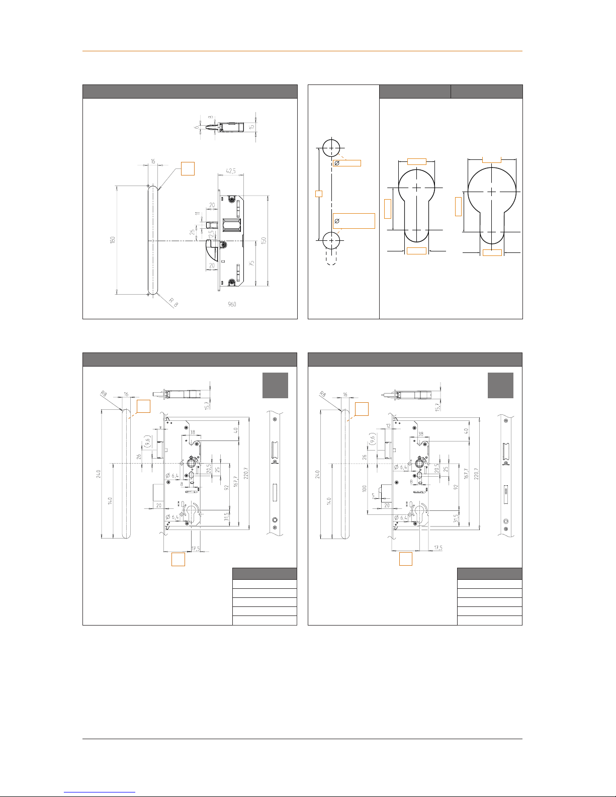
3.4 Main locks and auxiliary boxes
Auxiliary box PZ RZ
12 mm
21 mm
18 mm
12 mm
20 mm
24 mm
[A]
milling depth = route depth + 1 mm
Main lock type P, backset 30-55, PZ dimension 92 Main lock type Z, backset 45, PZ dimension 92
Backset [D]
35
40
45
55
65
Backset [D]
35
40
45
55
65
[A]
milling depth = route depth (backset + 17.5 mm) + 1 mm
[A]
milling depth = route depth (backset + 17.5 mm) + 1 mm
B
18 mm
PZ = 18 mm
RZ = 24 mm
P Z
A
A
D
A
D
Assembly instructions GENIUS 2.1 PANIC
Assembly of sash side
1303.2017
KFV
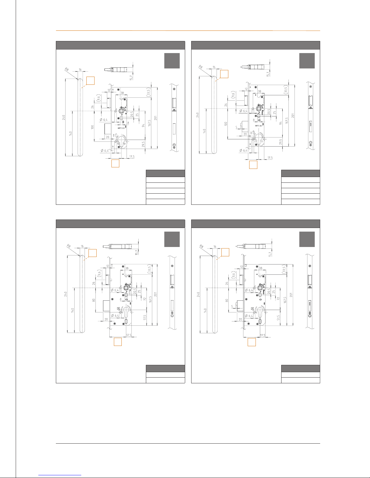
Main lock type P, backset 35-55, PZ dimension 94 Main lock type Z, backset 45, PZ dimension 94
Backset [D]
35
40
45
55
65
Backset [D]
35
40
45
55
65
[A]
milling depth = route depth + 1 mm
[A]
milling depth = route depth + 1 mm
Main lock type P, backset 55 and 65, PZ dimension 72 Main lock type Z, backset 55 and 65, PZ dimension 72
Backset [D]
55
65
Backset [D]
55
65
[A]
milling depth = route depth + 1 mm
[A]
milling depth = route depth + 1 mm
P Z
P Z
A
D
A
D
A
D
A
D
Assembly of sash side
Assembly instructions GENIUS 2.1 PANIC
14
03.2017
KFV
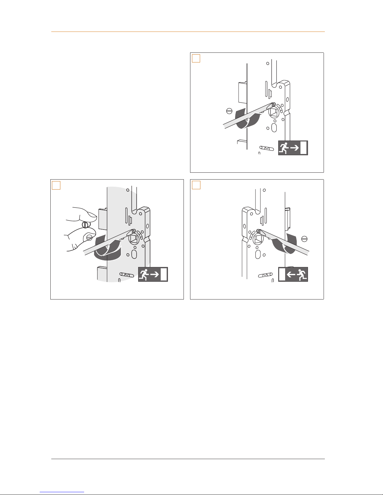
3.5 Change DIN orientation of the latches
The direction of escape can be changed by unscrewing
the grub screw above the nut and screwing it onto the
opposite side.
1
2
3
 Loading...