

Siebring ROYAL HEAT 240,ROYAL HEAT 360 Instructions Manual
ROYAL HEAT 240 / 360 GAS FURNACE
ROYAL HEAT 240 / 360 GAS FURNACE
ROYAL HEAT 240 / 360 GAS FURNACEROYAL HEAT 240 / 360 GAS FURNACE
INSTRUCTIONS
INSTRUCTIONS
INSTRUCTIONSINSTRUCTIONS
ATTENTION!
See special Methane
instructions on page 2425 & H17 pilot insert in
the back of this manual
Manufacturers of Quality Equipment Since 1910
PO Box 658 303 S. Main St. George, IA. 51237
Phone 888-475-3317 Fax 712-475-3490
www.siebringmfg.com Email sales@siebringmfg.com


TABLE OF CONTENTS:
1. Cover
2. Table of Contents
3. Condition of Sale - Warranty
4. Warnings & Cautions
5. General Information
6. General Information & Instructions
7. New Installations
8. Placement
9. Placement Options
10. Venting
11. Venting (continued)
12. Gas Supply Information
13. CO Level Standards
14. Gas Pipe Capacities
15. Pilot Adjustment
16. Square D electrical box
17. Electrical Diagram
18. Troubleshooting
19. Troubleshooting (continued)
20. Troubleshooting (continued)
21. Troubleshooting (continued)
22. Parts List
23. Parts Diagram – Furnace
24. Parts Diagram – Burner Tray
25. Special Requirements for Methane Furnaces
26. Special Instructions for Methane Furnaces
27. Specifications (dimensions, weight)
28. Specifications (continued) safety zone
Included: Robertshaw Gas Valve Installation Pamphlet, Honeywell
L4064 Fan & Limit Pamphlet, Honeywell Q327 Pilot Burners
Pamphlet, H17 Pilot Valve.
2

CONDITION OF SALE
SIEBRING MANUFACTURING, INC.
GEORGE, IA 51237
Pursuant to Magnuson-Moss Warranty Federal Trade Commission Improvement
Act P.L. 93-637, 88 STAT.2183-2193; U.P.C. 2301-2312 (Jan. 4, 1975), the
following limited warranty will now replace all prior warranties issued by Siebring
Manufacturing, Inc.
We warrant the equipment manufactured by us to be free from defects in material
and workmanship under normal use and service, our obligation under this
warranty being limited to replacing at our factory any product, or parts thereof,
which shall within one year after delivery thereof to the original purchaser be
returned to us with transportation (UPS Ground) charges prepaid, and which our
examination shall disclose to our satisfaction to have been thus defective. We
neither assume nor authorize any other person to assume for us any other liability
in connection with such equipment. “Overnight”, “Next Day” or any shipping
method other than UPS Ground will be the responsibility of the customer. This
warranty shall not apply to any equipment which shall have been repaired or
altered outside of our factory in any way so as to affect its stability and reliability,
nor which has been subject to misuse, negligence or accident, nor to any
equipment, which shall have been operated beyond factory rated capacity. We
shall not be liable for consequential damages caused by defective materials,
equipment or parts warranted by their respective manufacturers.
Any implied warranty (including the warranty of merchantability), to the extent
permitted by law, is excluded.
We will not grant any allowance for any repairs or alterations without written
approval of an executive officer, and we reserve the right to make changes in
design, or to make additions to, or improvements in, our products without
imposing any obligations upon the company to install them on products previously
manufactured.
Siebring Manufacturing is not responsible for installation costs.
3
FOR YOUR SAFETY
IF YOU SMELL GAS:
1. OPEN WINDOWS.
2. DON’T TOUCH ELECTRICAL SWITCHES.
3. EXTINGUISH ANY OPEN FLAMES.
4. DO NOT TRY TO LIGHT THE FURNACE
5. IMMEDIATELY CALL YOUR GAS SUPPLIER.
WARNING: Improper installation, adjustment, alteration,
service or maintenance can cause property damage,
injury or death. Read the installation, operating and
maintenance instructions thoroughly before installing or
servicing this equipment.
4

GENERAL INFO:
This unit complies with the American National Standard for Gas Unit Heaters
(special units, which are not AGA certified, may also use this manual).
1. The installation must conform with all local codes, or, in the absence of
local codes, it must follow the National Fuel Gas Code, ANSI Z223.1-1988.
2. All installation and servicing must be handled by qualified personnel.
3. This furnace should not be operated in an explosive or dusty environment.
4. This unit can be set up to run on Natural Gas or Liquid Propane (LP) gas.
The orifices must be sized appropriately for each gas type and pressure.
5. The draft hood provided with each furnace must be installed vertically in
the same air space as the furnace. This unit must be vented.
6. If this unit is used to heat an adjacent area, (not the same airspace as the
furnace is in) an adequate air return area must be provided.
7. In greenhouses, this unit may be positioned on four (4) concrete block or
bricks.
8. In garages, this unit should be suspended with at least 7’ of clearance
under the furnace. In garages, install this unit in accordance with the
Standard for Repair Garages ANSI / NFFA 88B and follow all local codes
that apply.
9. In aircraft hangars, this unit should be suspended with at least 10’ of
clearance from the wings or engine cowling, based on the highest aircraft
normally stored in the hangar. Install this furnace in accordance with the
Standard for Aircraft Hangars ANSI / NFPA 409.
10. Do not locate this unit closer than 12” to any combustible material, this
includes the chimney, all four sides and top of the unit. The furnace may
be set on any suitable non-combustible material.
11. Do not locate any items within 12” of the burner opening. This includes the
combustion air supply and the blower inlets. Floor drafts can cause pilot
outages.
12. If installed in parking structures, the Standard for Parking Structures ANSI /
NFPA 88A should be followed.
5
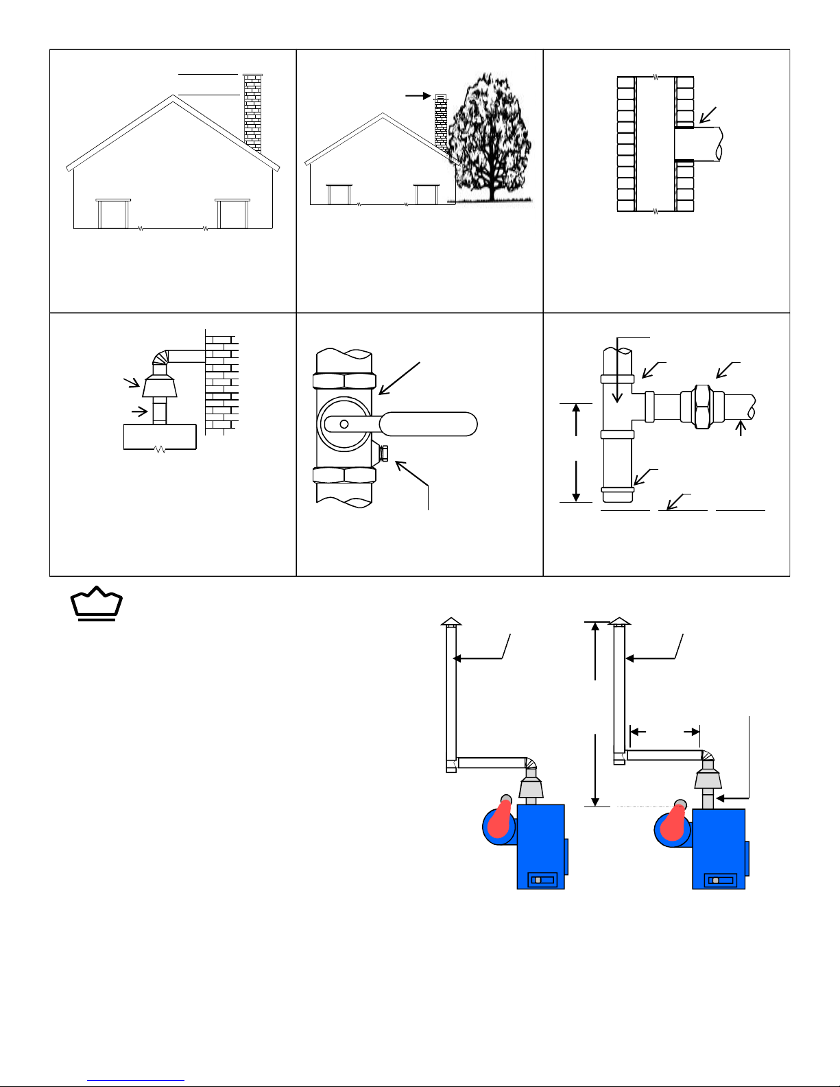
24”
Draft Cap
THIMBLE
The chimney height will be determined by the
surrounding roof & trees. The chimney should
extend at least 24” above the high point of the
roof with no obstructions from nearby roofs,
trees or other structures.
DRAFT
DIVERTER
12”
EXTENSION
(RH360)
Gas fired units will require less draft than coal
fired, however, a chimney flue with adequate
draft and capacity is required. An A.G.A. draft
diverter must be installed on all gas-fired
heating units.
Trim or remove any nearby trees that
would interfere with chimney draft
MANUAL SHUTOFF
VALVE
⅛” N.P.T. PLUGGED TAPPING
PRESSURE GAUGE PORT
RH240 Requires
8” Ø Stack
The vent pipe should extend only to
(and not beyond) the inside wall of the
chimney. Cement vent pipe tightly into
chimney opening.
DIRECTION OF FLOW
UNIONTEE
3” MIN
Location of union and drip leg for connecting
conversion burner to house piping
CONTROL MANIFOLD
PIPE CAP
FLOOR LEVEL
RH360 Requires
9” Ø Stack
ROYAL
Heaters
General Information & Instructions
-Unit crated weights: 240 = 640 lbs. / 360 = 780 lbs.
-Always use double wall pipe on gas units.
-Never have less than .02 - .04 inches of draft in the chimney.
-Always use black metal piping for gas (Nat./L.P.) installations.
-Rule of thumb for chimneys = 2’ vertical for every 1’ horizontal.
-Always check with the gas company on appropriate pipe sizing.
-Always check with the gas company to ensure adequate fuel supply.
-Never reduce the size of chimney from the furnace to the draft cap.
-Never run exhaust fans in any building while furnaces are in operation.
-Always vent gas fumes. Gas fumes not vented can cause death to plants, animals and humans.
-The draft diverter must always be installed VERTICALLY unless otherwise stated by Siebring Mfg.
Warranty will be void if venting does not meet local codes for gas venting.
6
240 360
20 ft.
10 ft.
I
RH360 Requires
a 12” Extension
between furnace
and draft diverter
I

NEW INSTALLATIONS
Electrical Information
Important!
Before beginning any electrical work, be
certain the electrical supply is disconnected.
For the furnace to operate properly, it must
be wired exactly as outlined in this manual.
Connect to 120 VAC 60 HZ 25A Service
An electrical diagram has been provided in this manual and on the face of the furnace.
1. If any wires as originally supplied are replaced, they should be replaced with type “T”
wires, with a 63°F (35°C) rise wire in similar colors.
2. Follow all local codes when wiring this furnace.
3. This furnace must be electrically grounded in accordance with the National Electrical
Code, ANSI / NFPA 70.
WIRE SIZE RATING @ 140° LINE LOSS WITH 15AMP
LOAD IN 100’ COPPER WIRE
14-3 15 AMP 8.0 VOLTS LOSS
12-3 20 AMP 5.5 VOLTS LOSS
10-3 30 AMP 3.0 VOLTS LOSS
8-3 40 AMP 1.9 VOLTS LOSS
Wire Size for 115 & 230 Volt Single Phase Circuits
Distance – Motor to Fuse or Motor to Meter Box
MOTOR
HP
1/4 # 14 # 14 # 10 # 12 # 8 # 10 # 6 # 8
1/3 # 12 # 14 # 10 # 12 # 6 # 10 # 4 # 8
1/2 # 10 # 12 # 8 # 10 # 6 # 8 # 4 # 6
3/4 # 10 # 12 # 6 # 10 # 4 # 8 # 2 # 6
1 # 8 # 10 # 6 # 8 # 4 # 6 # 4
100 FT. 200 FT. 300 FT. 500 FT.
115V 230V 115V 230V 115V 230V 115V 230V
1 ½ # 4 # 10 # 0 # 8 # 6 # 4
2 # 8 # 6 # 4 # 2
3 # 8 # 6 # 4 # 2
5 # 6 # 4 # 2 # 0
7

PLACEMENT:
This unit is designed to be used in various configurations. In greenhouses it
may be positioned directly on the ground or suspended from the greenhouse
structure. In aircraft hangars or garages, the unit will need to be suspended.
1. This unit may be suspended if necessary. Suitable framework, capable of handling
the weight of the furnace, can be fabricated from angle, channel or tubing material.
An eye bolt can be inserted in each corner or end of the angles, channels or beams to
provide 4 corner support (4 req.). These bolts can then be installed thru a suitable
ceiling joist etc.
2. Obviously, the structure must be strong enough to carry the additional weight of the
furnace, snow load and any possible future modifications or additions.
240 RH – 650#, 360 RH – 780#.
2. In greenhouses, this unit is normally installed on four (4) bricks setting directly on the
ground. A variety of openings can be supplied on these furnaces.
3. The furnaces require:
A. 12” distance to any combustible material. (See General Info for exceptions)
B. 12” of space for combustion air and blower supply air.
C. Approximately 1 sq. ft. of inlet area per 150,000 BTU/hr input. In many cases,
normal building cracks make up more than this area.
D. Approximately 5 sq. ft. of return air area. The heated air must have a free path
out of and back to the furnace. DO NOT restrict the discharge vents.
E. A barometric device (supplied by the manufacturer) in the same room as the
furnace. On the RH360 model, a 12” extension must be installed between the
barometric device and the furnace to prevent back draft and to prevent flue gases
from entering the blower inlet.
F. Plenty of access space for servicing the blower motor, burner, etc. Access must
also be provided to reach the gas valve and shut offs in case of an emergency.
G. That all local codes are followed when installing the regulation flue pipes.
8
 Loading...